WO2015093528A1 - 直動機構、調整弁駆動装置、蒸気タービン - Google Patents
直動機構、調整弁駆動装置、蒸気タービン Download PDFInfo
- Publication number
- WO2015093528A1 WO2015093528A1 PCT/JP2014/083409 JP2014083409W WO2015093528A1 WO 2015093528 A1 WO2015093528 A1 WO 2015093528A1 JP 2014083409 W JP2014083409 W JP 2014083409W WO 2015093528 A1 WO2015093528 A1 WO 2015093528A1
- Authority
- WO
- WIPO (PCT)
- Prior art keywords
- nut
- ball screw
- cylinder rod
- linear motion
- greasing
- Prior art date
- Legal status (The legal status is an assumption and is not a legal conclusion. Google has not performed a legal analysis and makes no representation as to the accuracy of the status listed.)
- Ceased
Links
Images


Classifications
-
- F—MECHANICAL ENGINEERING; LIGHTING; HEATING; WEAPONS; BLASTING
- F01—MACHINES OR ENGINES IN GENERAL; ENGINE PLANTS IN GENERAL; STEAM ENGINES
- F01D—NON-POSITIVE DISPLACEMENT MACHINES OR ENGINES, e.g. STEAM TURBINES
- F01D17/00—Regulating or controlling by varying flow
- F01D17/10—Final actuators
- F01D17/12—Final actuators arranged in stator parts
- F01D17/14—Final actuators arranged in stator parts varying effective cross-sectional area of nozzles or guide conduits
- F01D17/141—Final actuators arranged in stator parts varying effective cross-sectional area of nozzles or guide conduits by means of shiftable members or valves obturating part of the flow path
- F01D17/145—Final actuators arranged in stator parts varying effective cross-sectional area of nozzles or guide conduits by means of shiftable members or valves obturating part of the flow path by means of valves, e.g. for steam turbines
-
- F—MECHANICAL ENGINEERING; LIGHTING; HEATING; WEAPONS; BLASTING
- F01—MACHINES OR ENGINES IN GENERAL; ENGINE PLANTS IN GENERAL; STEAM ENGINES
- F01D—NON-POSITIVE DISPLACEMENT MACHINES OR ENGINES, e.g. STEAM TURBINES
- F01D25/00—Component parts, details, or accessories, not provided for in, or of interest apart from, other groups
- F01D25/24—Casings; Casing parts, e.g. diaphragms, casing fastenings
-
- F—MECHANICAL ENGINEERING; LIGHTING; HEATING; WEAPONS; BLASTING
- F01—MACHINES OR ENGINES IN GENERAL; ENGINE PLANTS IN GENERAL; STEAM ENGINES
- F01D—NON-POSITIVE DISPLACEMENT MACHINES OR ENGINES, e.g. STEAM TURBINES
- F01D5/00—Blades; Blade-carrying members; Heating, heat-insulating, cooling or antivibration means on the blades or the members
- F01D5/02—Blade-carrying members, e.g. rotors
-
- F—MECHANICAL ENGINEERING; LIGHTING; HEATING; WEAPONS; BLASTING
- F01—MACHINES OR ENGINES IN GENERAL; ENGINE PLANTS IN GENERAL; STEAM ENGINES
- F01D—NON-POSITIVE DISPLACEMENT MACHINES OR ENGINES, e.g. STEAM TURBINES
- F01D5/00—Blades; Blade-carrying members; Heating, heat-insulating, cooling or antivibration means on the blades or the members
- F01D5/12—Blades
-
- F—MECHANICAL ENGINEERING; LIGHTING; HEATING; WEAPONS; BLASTING
- F16—ENGINEERING ELEMENTS AND UNITS; GENERAL MEASURES FOR PRODUCING AND MAINTAINING EFFECTIVE FUNCTIONING OF MACHINES OR INSTALLATIONS; THERMAL INSULATION IN GENERAL
- F16H—GEARING
- F16H57/00—General details of gearing
- F16H57/04—Features relating to lubrication or cooling or heating
- F16H57/048—Type of gearings to be lubricated, cooled or heated
- F16H57/0497—Screw mechanisms
-
- F—MECHANICAL ENGINEERING; LIGHTING; HEATING; WEAPONS; BLASTING
- F16—ENGINEERING ELEMENTS AND UNITS; GENERAL MEASURES FOR PRODUCING AND MAINTAINING EFFECTIVE FUNCTIONING OF MACHINES OR INSTALLATIONS; THERMAL INSULATION IN GENERAL
- F16K—VALVES; TAPS; COCKS; ACTUATING-FLOATS; DEVICES FOR VENTING OR AERATING
- F16K31/00—Actuating devices; Operating means; Releasing devices
- F16K31/02—Actuating devices; Operating means; Releasing devices electric; magnetic
- F16K31/04—Actuating devices; Operating means; Releasing devices electric; magnetic using a motor
- F16K31/047—Actuating devices; Operating means; Releasing devices electric; magnetic using a motor characterised by mechanical means between the motor and the valve, e.g. lost motion means reducing backlash, clutches, brakes or return means
-
- F—MECHANICAL ENGINEERING; LIGHTING; HEATING; WEAPONS; BLASTING
- F05—INDEXING SCHEMES RELATING TO ENGINES OR PUMPS IN VARIOUS SUBCLASSES OF CLASSES F01-F04
- F05D—INDEXING SCHEME FOR ASPECTS RELATING TO NON-POSITIVE-DISPLACEMENT MACHINES OR ENGINES, GAS-TURBINES OR JET-PROPULSION PLANTS
- F05D2220/00—Application
- F05D2220/30—Application in turbines
- F05D2220/31—Application in turbines in steam turbines
-
- F—MECHANICAL ENGINEERING; LIGHTING; HEATING; WEAPONS; BLASTING
- F05—INDEXING SCHEMES RELATING TO ENGINES OR PUMPS IN VARIOUS SUBCLASSES OF CLASSES F01-F04
- F05D—INDEXING SCHEME FOR ASPECTS RELATING TO NON-POSITIVE-DISPLACEMENT MACHINES OR ENGINES, GAS-TURBINES OR JET-PROPULSION PLANTS
- F05D2260/00—Function
- F05D2260/50—Kinematic linkage, i.e. transmission of position
- F05D2260/57—Kinematic linkage, i.e. transmission of position using servos, independent actuators, etc.
-
- F—MECHANICAL ENGINEERING; LIGHTING; HEATING; WEAPONS; BLASTING
- F05—INDEXING SCHEMES RELATING TO ENGINES OR PUMPS IN VARIOUS SUBCLASSES OF CLASSES F01-F04
- F05D—INDEXING SCHEME FOR ASPECTS RELATING TO NON-POSITIVE-DISPLACEMENT MACHINES OR ENGINES, GAS-TURBINES OR JET-PROPULSION PLANTS
- F05D2270/00—Control
- F05D2270/50—Control logic embodiments
- F05D2270/58—Control logic embodiments by mechanical means, e.g. levers, gears or cams
-
- F—MECHANICAL ENGINEERING; LIGHTING; HEATING; WEAPONS; BLASTING
- F05—INDEXING SCHEMES RELATING TO ENGINES OR PUMPS IN VARIOUS SUBCLASSES OF CLASSES F01-F04
- F05D—INDEXING SCHEME FOR ASPECTS RELATING TO NON-POSITIVE-DISPLACEMENT MACHINES OR ENGINES, GAS-TURBINES OR JET-PROPULSION PLANTS
- F05D2270/00—Control
- F05D2270/60—Control system actuates means
- F05D2270/62—Electrical actuators
-
- F—MECHANICAL ENGINEERING; LIGHTING; HEATING; WEAPONS; BLASTING
- F16—ENGINEERING ELEMENTS AND UNITS; GENERAL MEASURES FOR PRODUCING AND MAINTAINING EFFECTIVE FUNCTIONING OF MACHINES OR INSTALLATIONS; THERMAL INSULATION IN GENERAL
- F16H—GEARING
- F16H25/00—Gearings comprising primarily only cams, cam-followers and screw-and-nut mechanisms
- F16H25/18—Gearings comprising primarily only cams, cam-followers and screw-and-nut mechanisms for conveying or interconverting oscillating or reciprocating motions
- F16H25/20—Screw mechanisms
- F16H25/22—Screw mechanisms with balls, rollers, or similar members between the co-operating parts; Elements essential to the use of such members
- F16H25/2204—Screw mechanisms with balls, rollers, or similar members between the co-operating parts; Elements essential to the use of such members with balls
Definitions
- the present invention relates to a linear motion mechanism, a regulating valve driving device using the linear motion mechanism, and a steam turbine.
- the steam turbine is used for machine driving and the like, and includes a turbine body having a rotor that is rotatably supported. The rotor is driven to rotate by supplying steam as a working fluid to the turbine body. Steam supplied to the turbine body and steam extracted from the turbine body flow through the steam flow path of the steam turbine. An adjustment valve is provided in the steam channel. The flow rate of the steam supplied to the turbine body can be adjusted by adjusting the opening of the adjusting valve.
- Patent Document 1 discloses an adjusting valve driving device that includes an electric motor and a conversion mechanism such as a ball screw that converts the rotational motion of the electric motor into linear motion of the adjusting valve. Since the ball screw has a meshing portion having a contact angle in a spiral thread groove, when the opening / closing operation of the adjusting valve is repeatedly performed over a long period of time, only a specific portion of the ball screw meshing portion is worn. There is.
- Patent Document 2 discloses a configuration in which a ball screw nut into which a ball screw shaft having a thread groove formed on the outer peripheral surface is screwed is externally lubricated.
- Patent Document 3 discloses a configuration in which a ball screw is accommodated in a cylindrical housing, and an oil supply conduit is provided for supplying grease to the ball screw nut screwed into the ball screw shaft from the outside.
- the oil supply line is provided inside the stator of the electric motor for rotating the ball screw, and rotates integrally with the rotor.
- JP 2013-72349 A Japanese Patent No. 4784748 Japanese Patent No. 4005444
- Patent Document 2 The configuration described in Patent Document 2 described above needs to lubricate the ball screw nut. However, when the ball screw is accommodated in the housing as in the configuration described in Patent Document 3, the configuration described in Patent Document 2 takes time and effort to access the ball screw nut.
- Patent Document 3 is effective in a drive type in which a ball screw nut is fixed and the ball screw shaft advances and retreats with respect to the ball screw nut.
- the configuration described in Patent Document 3 cannot be applied to a drive type in which the ball screw shaft is fixed and the ball screw nut advances and retreats along the ball screw shaft.
- the present invention has been made in view of the above circumstances, and can be easily lubricated regardless of the drive type of the ball screw, and can provide high reliability.
- An object is to provide a steam turbine.
- a linear motion mechanism includes an electric motor, a ball screw that is driven to rotate about an axis by the electric motor, the screw screwed into the ball screw, and the rotation of the ball screw.
- the lubricating oil When lubricating the ball screw, if the lubricating oil is injected into the cylinder rod side greasing hole from the injection port in the cylinder rod formed at the position exposed to the outside of the casing, the injected lubricating oil is supplied to the cylinder rod side. It flows from the other end of the grease hole to the nut side grease supply hole.
- the lubricating oil that has flowed into the nut-side greasing hole is supplied from the discharge port of the nut-side greasing hole toward the outer peripheral surface of the ball screw. That is, in the linear motion mechanism in which the ball screw and the nut are accommodated in the casing, the grease can be supplied from the outside of the casing.
- grease can be supplied in any of the drive type in which the ball screw advances and retreats with respect to the nut and the drive type in which the nut advances and retreats along the ball screw.
- a linear motion mechanism according to a second aspect of the present invention is the linear motion mechanism according to (1), wherein the linear motion mechanism has flexibility and is connected to the inlet of the cylinder rod-side greasing hole. And a grease supply device for supplying lubricating oil from the outside via the grease supply tube.
- the lubricating oil supplied from the outside by the greasing device can be injected from the inlet of the cylinder rod-side greasing hole via the greasing pipe.
- the greasing pipe is flexible, it is possible to lubricate the nut while continuing the operation even if the nut is driven and retracted along the ball screw.
- a linear motion mechanism is the linear motion mechanism according to (1) or (2), wherein the linear motion mechanism is formed on the nut and has an opening position at one end of the nut-side greasing hole. Is provided at one end with a nut-side discharge hole having an inflow opening at one end toward the outer peripheral surface of the ball screw at one end, and an outflow opening formed at the cylinder rod and opened at a position exposed to the outside of the casing. And a cylinder rod side discharge hole whose other end communicates with the nut side discharge hole.
- a linear motion mechanism according to a fourth aspect of the present invention is the linear motion mechanism according to (3), wherein the linear motion mechanism is connected to the outlet of the cylinder rod side discharge hole and lubricates from the cylinder rod side discharge hole.
- a flexible discharge pipe for discharging the oil and fat to the outside is further provided.
- emitted from the outflow port of a cylinder rod side discharge hole can be discharged
- the discharge pipe has flexibility, even if it is a drive type in which the nut advances and retreats along the ball screw, the excess lubricating oil and fat accompanying the lubrication is discharged while continuing the operation. Is possible.
- the linear motion mechanism according to the fifth aspect of the present invention is the linear motion mechanism according to (4), wherein the iron powder concentration for detecting the iron powder concentration contained in the lubricating oil discharged from the discharge pipe A detection device is further provided.
- An adjustment valve drive apparatus is an adjustment valve drive apparatus for an adjustment valve that opens and closes a flow path through which the working fluid flows to adjust the flow rate of the working fluid.
- a steam turbine according to a seventh aspect of the present invention linearly moves with a turbine body having blades rotatably supported, a steam passage connected to the turbine body and through which steam flows.
- An adjustment valve that adjusts opening and closing of the steam flow path, and an adjustment valve driving device according to (6) that drives the adjustment valve are provided.
- the linear motion mechanism, the regulating valve drive device, and the steam turbine according to the present invention it is possible to supply grease to the linear motion mechanism from the outside of the casing. This makes it easy to lubricate regardless of the drive type of the ball screw. As a result, the maintenance of the ball screw can be performed easily and reliably, and high reliability can be obtained.
- FIG. 1 is a schematic diagram showing an overall configuration of a steam turbine 10 according to a first embodiment of the present invention.
- the steam turbine 10 of this embodiment includes a turbine body 11, a steam flow path 12 through which steam as a working fluid flows, a regulating valve 13, a lever member 14, and a regulating valve drive device 15. And an electronic governor 17 for controlling the regulating valve driving device 15.
- the turbine body 11 includes a cylindrical casing 111, a bearing 112 provided in the casing 111, a rotor 113 rotatably supported by the bearing 112, and a rotation speed of the rotor 113. And a speed detection sensor 114.
- the rotor 113 includes a rotating shaft 115 and a plurality of blades 116 fixed to the rotating shaft 115. The blade 116 configured in this manner is rotated by steam, and the compressor 18 is driven by the rotational force.
- the steam channel 12 is a channel that supplies steam as a working fluid to the turbine body 11. Steam is introduced into the steam channel 12 from a steam inlet 121 on one end side thereof.
- the steam supply port 122 on the other end side of the steam flow path 12 is connected to the turbine body 11. Further, between the steam introduction port 121 and the steam supply port 122, a throttle hole 123 whose channel width is narrowed is provided.
- a “steam channel” a channel through which steam supplied to the turbine body 11 flows will be described as an example.
- the steam channel 12 is not limited to this, and may be a channel through which steam extracted from the turbine body 11 flows, for example.
- the adjusting valve 13 adjusts the amount of steam supplied to the turbine body 11.
- the adjustment valve 13 includes a rod-shaped arm member 131 and a substantially semicircular sealing member (valve element) 132 provided at the tip of the arm member 131.
- the arm member 131 has a base end portion rotatably attached to an intermediate portion in the longitudinal direction of the lever member 14. Since the regulating valve 13 has the above-described configuration, the arm member 131 linearly moves along the steam flow path 12, so that the sealing member 132 at the distal end thereof is relative to the throttle hole 123 of the steam flow path 12. Fit or separate (in other words, open and close). Thereby, the size of the opening between the throttle hole 123 and the sealing member 132 changes. Therefore, the flow rate of the steam supplied to the turbine body 11 through the throttle hole 123 changes.
- the lever member 14 is a member that transmits the output of the regulating valve driving device 15 to the regulating valve 13 and moves the sealing member 132 forward and backward with respect to the steam flow path 12.
- the lever member 14 is supported so that the base end portion in the longitudinal direction (the right end portion in FIG. 1) can rotate.
- One end of the lever side rod 19 is rotatably attached to the longitudinal end of the lever member 14.
- the base end portion of the arm member 131 constituting the adjustment valve 13 is rotatably attached to the middle portion of the lever member 14 in the longitudinal direction.
- the lever member 14 has one end of the tension spring 20 attached to the distal end side in the longitudinal direction of the lever member 14 with respect to the attachment position of the arm member 131.
- the tension spring 20 functions as a forced closing means for forcibly closing the adjustment valve 13.
- the other end of the tension spring 20 is fixed to a frame (not shown) or the like of the steam flow path 12 and cannot move. That is, the tension spring 20 applies a tensile force that rotates the lever member 14 counterclockwise in FIG. 1 in a state where no external force is applied.
- the adjusting valve driving device 15 is a mechanism for driving the adjusting valve 13 described above.
- the regulating valve driving device 15 includes an electric actuator 23.
- the electric actuator 23 includes a pair of brackets 21 that are fixedly installed on a pedestal or the like, and a holding member 22 that is rotatably supported by the brackets 21.
- the holding member 22 holds an electric actuator 23.
- FIG. 2 is a perspective view showing the periphery of the regulating valve driving device 15.
- the pair of brackets 21 have a substantially L-shaped cross section.
- the pair of brackets 21 are fixed on the base 25.
- the pedestal 25 is provided close to the bearing cover 24.
- the bearing cover 24 accommodates a bearing 112 that rotatably supports the rotating shaft 115 of the rotor 113 shown in FIG.
- the holding member 22 is substantially U-shaped in a side view. Both ends of the holding member 22 are supported by the pair of brackets 21 so as to be rotatable.
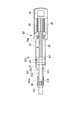
- FIGS. 3A and 3B are cross-sectional views showing the internal configuration of the electric actuator 23.
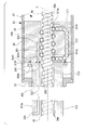
- FIG. FIG. 4 is an enlarged cross-sectional view of a main part showing the configuration of the greasing mechanism of the ball screw mechanism 27.
- the electric actuator 23 includes a ball screw mechanism (linear motion mechanism) 27 and a brake 28.
- the ball screw mechanism 27 is a mechanism that converts the rotational motion of the electric motor 26 into the linear motion of the lever side rod 19.
- the ball screw mechanism 27 includes an electric motor 26, a ball screw 30 connected to a drive shaft of the electric motor 26 and driven to rotate about the axis by the electric motor 26, and a ball screw in the axial direction of the ball screw 30 as the ball screw 30 rotates. And a piston unit 31 that moves forward and backward relative to 30.
- the electric motor 26 rotates upon receiving power.
- the electric motor 26 is accommodated in the motor accommodating portion 29.
- the motor housing portion 29 is provided at the proximal end portion of the electric actuator 23 and is sealed inside. Thereby, it has an explosion-proof structure in which the electric motor 26 is isolated from the oil existing around it.
- the ball screw 30 is a long screw member, and a female screw groove 30m is formed on the outer peripheral surface thereof. One end of the ball screw 30 is connected to the drive shaft of the electric motor 26. The ball screw 30 is driven to rotate as the electric motor 26 rotates.
- the electric actuator 23 includes a brake 28 at a position opposite to the ball screw 30 across the electric motor 26.
- the brake 28 is an electromagnetic disc brake.
- the brake 28 is actuated when the supply of electric power is cut off to brake the rotation of the electric motor 26.
- the operation of the brake 28 is controlled by the electronic governor 17 (see FIG. 1).
- the electronic governor 17 operates the brake 28 when the peripheral speed of the ball screw 30 exceeds the threshold value. That is, the brake 28 is operated to brake the rotation of the electric motor 26.
- the piston unit 31 reciprocates along the ball screw 30.
- the piston unit 31 includes a nut 311, a cylinder rod 312, a rod end connector 313, and an actuator side rod 314.
- the nut 311 is a substantially annular member that is screwed into the ball screw 30. As shown in FIG. 4, a female thread groove 311 m is formed on the inner peripheral surface of the nut 311. A large number of balls 316 are interposed between the female screw groove 311 m on the inner peripheral surface of the nut 311 and the female screw groove 30 m on the outer peripheral surface of the ball screw 30. When these balls 316 roll between the female screw groove 311m and the female screw groove 30m, the nut 311 and the ball screw 30 rotate relatively around the central axis C of the ball screw 30, and the nut 311 and The ball screw 30 is relatively displaced along the central axis C direction.
- a circulation path 317 for circulating the ball 316 between one end side and the other end side of the nut 311 is formed in the nut 311. Both end portions 317 a and 317 b of the circulation path 317 open to the inner peripheral surface of the nut 311 on one end side and the other end side of the nut 311.
- the cylinder rod 312 is formed in a cylindrical shape that covers the outside of the ball screw 30 so that the ball screw 30 can be inserted into the cylinder rod 312.
- a flange portion 312f is formed at the base end portion of the cylinder rod 312 so as to project outward.
- the cylinder rod 312 is fixed to one end surface 311f of the nut 311 with bolts 315 at a plurality of locations in the circumferential direction of the flange portion 312f.
- the rod end connector 313 is a member attached to the tip of the cylinder rod 312.
- the rod end connector 313 has a female screw formed on the inner peripheral surface on the distal end side.
- the actuator side rod 314 is a member that extends in the direction in which the cylinder rod 312 extends.
- the actuator-side rod 314 has a male thread at one end in the longitudinal direction.
- the male screw of the actuator side rod 314 is screwed into and fixed to the female screw of the rod end connector 313.
- the ball screw 30 and the nut 311 are surrounded by a piston casing (casing) 36.
- the outer peripheral surface of the nut 311 is fixed to the inner peripheral surface of the piston casing 36, and the rotation around the central axis C is restricted.
- the piston casing 36 includes a piston cap 37 that seals the piston casing 36 at the upper end (the left end in FIGS. 3A and 3B).
- a through hole 37h is formed in the piston cap 37, and the cylinder rod 312 is projected and retracted through the through hole 37h. At this time, the tip 312 a of the cylinder rod 312 is always exposed to the outside from the piston casing 36 and the piston cap 37.
- FIG. 5 is a perspective view showing the periphery of the electric actuator 23.
- the electric actuator 23 is fixed to the holding member 22.
- the actuator side rod 314 is inserted through an insertion hole 39 a of a guide plate 39 provided at the upper end of the holding member 22.
- the actuator side rod 314 is connected to the lever side rod 19.
- the electric actuator 23 installed in this way rotates around the position where the holding member 22 is supported by the bracket 21 following the swing of the lever member 14. It can be done.
- the electronic governor 17 controls the operation of the regulating valve driving device 15. As shown in FIG. 1, the electronic governor 17 receives the result of process control based on the pressure and temperature detection results in the compressor 18. Further, the rotation speed of the blade 116 detected by the speed detection sensor 114 constituting the turbine body 11 is input to the electronic governor 17. Further, an instruction from the user input from the operation panel 34 is input to the electronic governor 17. The electronic governor 17 controls the operation of the regulating valve driving device 15 based on these inputs. More specifically, the electronic governor 17 controls the operation of the electric motor 26 constituting the electric actuator 23 based on the above inputs. Then, the regulating valve 13 is driven by the electric actuator 23.
- the ball screw mechanism 27 is provided with a nut-side greasing hole 321 formed in the nut 311 and a cylinder rod-side greasing hole 322 formed in the cylinder rod 312 as a greasing mechanism. It has been.
- the nut-side greasing hole 321 has, at one end thereof, a discharge port 323 that opens toward the outer peripheral surface of the ball screw 30 on the inner peripheral surface of the nut 311.
- the nut-side greasing hole 321 extends in the direction along the central axis C, and the other end 321 b is open to one end surface 311 f of the nut 311.
- the cylinder rod-side greasing hole 322 has an inlet 324 that opens at the outer peripheral surface of the cylinder rod 312 at one end thereof.
- the inlet 324 is formed at a position where the cylinder rod 312 is always exposed to the outside of the piston casing 36.
- the other end 322 b of the cylinder rod side greasing hole 322 opens to the flange portion 312 f of the cylinder rod 312 and communicates with the nut side greasing hole 321. That is, the opening at the other end 322b of the cylinder rod side greasing hole 322 and the opening at the other end 321b of the nut side greasing hole 321 are connected to face each other, whereby the cylinder rod side greasing hole 322 and the nut are connected.
- the side greasing holes 321 communicate with each other.
- an annular seal member 325 is interposed between the flange portion 312f and one end surface 311f of the nut 311 to seal the periphery of the connecting portion between the cylinder rod-side greasing hole 322 and the nut-side greasing hole 321. is doing.
- the lubricating oil is supplied to the cylinder rod 312 from the inlet 324 formed at a position exposed to the outside of the piston casing 36 on the cylinder rod side. Inject into the hole 322. Then, the injected lubricating oil flows from the other end 322 b of the cylinder rod side greasing hole 322 to the nut side greasing hole 321. Then, lubricating oil is supplied from the discharge port 323 of the nut-side greasing hole 321 toward the outer peripheral surface of the ball screw 30.
- the cylinder rod 312 is provided with the cylinder rod-side greasing hole 322 communicating with the nut-side greasing hole 321.
- An injection port 324 for injecting lubricating oil into the cylinder rod side greasing hole 322 is formed at a position exposed to the outside of the piston casing 36. Therefore, in the ball screw mechanism 27 in which the ball screw 30 and the nut 311 are accommodated in the piston casing 36, it is possible to supply grease from the outside of the piston casing 36. As a result, maintenance of the ball screw 30 can be performed easily and reliably, and the reliability of the ball screw mechanism 27, the regulating valve driving device 15 including the ball screw mechanism 27, and the steam turbine 10 can be improved.
- FIG. 6 is an enlarged cross-sectional view of a main part showing a configuration of a greasing mechanism of the ball screw mechanism 27 of the steam turbine 10 in the second embodiment.
- the ball screw mechanism 27 includes a nut-side greasing hole 321 formed in the nut 311 and a cylinder rod formed in the cylinder rod 312 as a greasing mechanism. Side greasing holes 322 are provided.
- a flexible greasing pipe 341 made of a rubber-based material, a soft resin-based material, a flexible metal tube, or the like is connected to the inlet 324 of the cylinder rod-side greasing hole 322.
- a grease supply device 342 for supplying lubricating oil from the outside is connected to the grease supply pipe 341.
- the greasing device 342 can supply lubricating oil to the inlet 324 through the greasing pipe 341 every predetermined operating time or the like.
- the lubricating oil is supplied from the outside by the greasing device 342 and injected from the inlet 324 of the cylinder rod-side greasing hole 322 through the greasing pipe 341, thereby supplying the ball screw mechanism 27. Fats can be made automatically. Since the greasing tube 341 has flexibility, even if the nut 311 moves back and forth along the ball screw 30, the greasing tube 341 can be deformed following this. Therefore, it is possible to lubricate while continuing the operation.
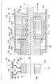
- FIG. 7 is an enlarged cross-sectional view of the main part showing the configuration of the greasing mechanism of the ball screw mechanism 27 of the steam turbine 10 in the third embodiment.
- a greasing mechanism for the ball screw mechanism 27 As shown in FIG. 7, as in the second embodiment, as a greasing mechanism for the ball screw mechanism 27, a nut-side greasing hole 321 formed in the nut 311 and a cylinder rod-side feeding provided in the cylinder rod 312. The oil hole 322 is provided.
- the ball screw mechanism 27 has a greasing pipe 341 connected to the inlet 324 of the cylinder rod side greasing hole 322.
- a grease supply device 342 for supplying lubricating oil from the outside is connected to the grease supply pipe 341.
- the ball screw mechanism 27 has a nut-side discharge hole 331 formed in the nut 311 and a cylinder rod-side discharge hole 332 formed in the cylinder rod 312.
- the nut-side discharge hole 331 has an inlet 333 that opens toward the outer peripheral surface of the ball screw 30 at one end of the nut-side discharge hole 331 at a position different from the opening position of the discharge port 323 at one end of the nut-side greasing hole 321. .
- the inlet 333 is formed outside the nut 311 in the nut 311 rather than the end 317 b of the circulation path 317 for circulating the ball 316.
- the cylinder rod side discharge hole 332 is provided at one end thereof with an outflow port 334 that opens to a position exposed to the outside of the piston casing 36 on the outer peripheral surface of the cylinder rod 312.
- the other end 332b of the cylinder rod side discharge hole 332 and the other end 331b of the nut side discharge hole 331 communicate with each other at a facing portion where the flange portion 312f and the one end surface 311f of the nut 311 face each other. That is, the opening at the other end 332b of the cylinder rod side discharge hole 332 and the opening at the other end 331b of the nut side discharge hole 331 are connected to face each other, whereby the cylinder rod side discharge hole 332 and the nut side discharge hole are connected.
- An annular seal member 326 is interposed between the flange portion 312f and one end surface 311f of the nut 311 to seal the periphery of the connecting portion between the cylinder rod side discharge hole 332 and the nut side discharge hole 331.
- a flexible discharge pipe 351 is connected to the outlet 334 of the cylinder rod side discharge hole 332.
- the discharge pipe 351 is connected to a discharge device 352 such as a pump for discharging the lubricating oil from the cylinder rod side discharge hole 332 to the outside.
- An iron powder concentration detection device 353 that detects the concentration of iron powder contained in the lubricating oil discharged from the discharge pipe 351 is connected to the discharge device 352.
- warning information is output by an alarm sound, an alarm lamp, or the like by the controller of the steam turbine 10 or the like. It may be.
- the lubricating oil is supplied from the outside via the greasing pipe 341 by the greasing device 342, and the ball screw mechanism 27 can be automatically lubricated. . Further, the lubricating oil discharged from the outlet 334 of the cylinder rod side discharge hole 332 can be discharged to the outside through the discharge pipe 351. Further, the lubricating oil / fat discharged from the outlet 334 is sucked by the discharging device 352, whereby the lubricating oil / fat can be discharged more quickly. Furthermore, since the discharge pipe 351 has flexibility, even if the nut 311 advances and retreats along the ball screw 30, it is possible to discharge excess lubricating oil and fat accompanying lubrication while continuing operation. Become.
- the iron powder concentration detecting device 353 by detecting the iron powder concentration contained in the discharged lubricating oil and fat in the iron powder concentration detecting device 353, it becomes possible to detect the wear and damage of the ball screw 30 and the nut 311. Thereby, maintenance of the ball screw mechanism 27 can be performed at an appropriate timing, and the reliability of the ball screw mechanism 27, the regulating valve driving device 15 including the ball screw mechanism 27, and the steam turbine 10 is further enhanced.
- the present invention is not limited to the above-described embodiment, and includes various modifications made to the above-described embodiment without departing from the spirit of the present invention. That is, the specific shapes, configurations, and the like given in the embodiment are merely examples, and can be changed as appropriate.
- the nut 311 is fixed and the ball screw 30 moves forward and backward with respect to the nut 311.
- the present invention is not limited to this. Even in a drive type in which the nut 311 advances and retreats along the ball screw 30, the grease can be reliably supplied with the same configuration as described above.
- the ball screw mechanism 27 is not limited to the regulating valve driving device 15 and the steam turbine 10, and can be used for various applications.
- the configurations shown in the first to third embodiments can be appropriately selected and combined. In addition to this, the overall configuration and the like of the regulating valve driving device 15 and the steam turbine 10 can be appropriately changed within the scope of the gist of the present invention.
- the linear motion mechanism, the regulating valve drive device, and the steam turbine according to the present invention it is possible to supply grease to the linear motion mechanism from the outside of the casing. This makes it easy to lubricate regardless of the drive type of the ball screw. As a result, the maintenance of the ball screw can be performed easily and reliably, and high reliability can be obtained.
Landscapes
- Engineering & Computer Science (AREA)
- General Engineering & Computer Science (AREA)
- Mechanical Engineering (AREA)
- Transmission Devices (AREA)
- Control Of Turbines (AREA)
- Mechanically-Actuated Valves (AREA)
Abstract
本発明の直動機構(27)は、基端部がピストンケーシング(36)の内部でナット(311)に接続され、先端部(312a)がピストンケーシング(36)の外部に露出し、ボールネジ(30)が内部に挿通可能なシリンダロッド(312)と、ナット(311)に形成され、ボールネジ(30)の外周面に向けて開口した吐出口(323)を有するナット側給脂孔(321)と、シリンダロッド(312)に形成され、一端にピストンケーシング(36)の外部に露出した位置に開口した注入口(324)を有し、他端(322b)がナット側給脂孔(321)に連通したシリンダロッド側給脂孔(322)と、を備えている。
Description
この発明は、直動機構、およびそれを用いた調整弁駆動装置、蒸気タービンに関する。
本願は、2013年12月18日に日本に出願された特願2013-261808号について優先権を主張し、その内容をここに援用する。
本願は、2013年12月18日に日本に出願された特願2013-261808号について優先権を主張し、その内容をここに援用する。
蒸気タービンは、機械駆動用などに用いられ、回転可能に支持されたロータを有するタービン本体を備えている。ロータは、タービン本体に対して作動流体としての蒸気が供給されることによって回転駆動される。蒸気タービンの蒸気流路には、タービン本体へ供給する蒸気やタービン本体から抽気した蒸気が流れる。蒸気流路には、調整弁が設けられている。この調整弁の開度を調整することによって、タービン本体に供給する蒸気の流量が調整可能となっている。
調整弁は、調整弁駆動装置により駆動される。例えば、特許文献1には、電動モータと、電動モータの回転運動を調整弁の直線運動に変換するボールネジ等の変換機構と、を備える調整弁駆動装置が開示されている。
ボールネジは、螺旋状のネジ溝において接触角を有した噛み合い部があるため、長期間にわたって調整弁の開閉動作を繰り返し行っていると、ボールネジの噛み合い部の特定部分のみが摩耗してくるという課題がある。
ボールネジは、螺旋状のネジ溝において接触角を有した噛み合い部があるため、長期間にわたって調整弁の開閉動作を繰り返し行っていると、ボールネジの噛み合い部の特定部分のみが摩耗してくるという課題がある。
特許文献2には、外周面にネジ溝が形成されたボールネジ軸がねじ込まれたボールネジナットに、外部から給脂する構成が開示されている。
特許文献3には、ボールネジを筒状のハウジングに収容し、ボールネジ軸にねじ込まれたボールネジナットに対して外部から給脂するための給油管路を設けた構成が開示されている。この構成においては、給油管路は、ボールネジを回転駆動させるための電動モータのステータの内方に設けられ、ロータと一体に回転するようになっている。
上述した特許文献2に記載の構成は、ボールネジナットに給脂する必要がある。しかし、特許文献3に記載された構成のように、ボールネジをハウジングに収容する場合、特許文献2に記載の構成では、ボールネジナットにアクセスするために、手間がかかる。
これに対し、特許文献3に記載の構成においては、ハウジングの外部から給油管路を経て給脂を行うことができるので、手間がかからない。しかし、特許文献3に記載の構成においては、給油管路や、給油管路をロータと一体に回転させるためのロータリージョイント等が必要である。したがって、装置が複雑化し、コストがかかるのに加え、給脂系統において故障等が生じる可能性がある。
さらに、特許文献3に記載の構成では、給油管路は、ロータとともに回転するものの、ボールネジの軸方向における給油管路の位置は、ロータやハウジングとともに固定されている。つまり、特許文献3に記載の構成は、ボールネジナットが固定され、ボールネジナットに対してボールネジ軸が進退する駆動形式において有効である。しかし、ボールネジ軸が固定され、ボールネジナットがボールネジ軸に沿って進退する駆動形式には、特許文献3に記載の構成は適用することができない。
さらに、特許文献3に記載の構成では、給油管路は、ロータとともに回転するものの、ボールネジの軸方向における給油管路の位置は、ロータやハウジングとともに固定されている。つまり、特許文献3に記載の構成は、ボールネジナットが固定され、ボールネジナットに対してボールネジ軸が進退する駆動形式において有効である。しかし、ボールネジ軸が固定され、ボールネジナットがボールネジ軸に沿って進退する駆動形式には、特許文献3に記載の構成は適用することができない。
この発明は、上記事情に鑑みてなされたものであり、ボールネジの駆動形式に関わらず、給脂を容易に行うことができ、高い信頼性を得ることのできる直動機構、調整弁駆動装置、蒸気タービンを提供することを目的とする。
この発明は、上記課題を解決するため、以下の手段を採用する。
(1)この発明の第一の態様に係る直動機構は、電動モータと、前記電動モータによって軸回りに回転駆動されるボールネジと、前記ボールネジにねじ込まれて、前記ボールネジの回転に伴って前記ボールネジの軸方向に前記ボールネジに対して相対的に進退するナットと、前記ボールネジ及び前記ナットを囲むケーシングと、基端部が前記ケーシングの内部で前記ナットに接続され、先端部が前記ケーシングの外部に露出し、前記ボールネジが内部に挿通可能な筒状のシリンダロッドと、前記ナットに形成され、前記ボールネジの外周面に向けて開口した吐出口を有するナット側給脂孔と、前記シリンダロッドに形成され、一端に前記ケーシングの外部に露出した位置に開口した注入口を有し、他端が前記ナット側給脂孔に連通したシリンダロッド側給脂孔と、を備えている。
(1)この発明の第一の態様に係る直動機構は、電動モータと、前記電動モータによって軸回りに回転駆動されるボールネジと、前記ボールネジにねじ込まれて、前記ボールネジの回転に伴って前記ボールネジの軸方向に前記ボールネジに対して相対的に進退するナットと、前記ボールネジ及び前記ナットを囲むケーシングと、基端部が前記ケーシングの内部で前記ナットに接続され、先端部が前記ケーシングの外部に露出し、前記ボールネジが内部に挿通可能な筒状のシリンダロッドと、前記ナットに形成され、前記ボールネジの外周面に向けて開口した吐出口を有するナット側給脂孔と、前記シリンダロッドに形成され、一端に前記ケーシングの外部に露出した位置に開口した注入口を有し、他端が前記ナット側給脂孔に連通したシリンダロッド側給脂孔と、を備えている。
ボールネジに給脂を行うに際して、ケーシングの外部に露出する位置に形成されたシリンダロッドにおいて注入口から、潤滑油脂をシリンダロッド側給脂孔に注入すると、注入された潤滑油脂は、シリンダロッド側給脂孔の他端からナット側給脂孔へと流れる。このナット側給脂孔へと流れた潤滑油脂は、ナット側給脂孔の吐出口から、ボールネジの外周面に向けて供給される。つまり、ケーシングにボールネジおよびナットが収容された直動機構において、ケーシングの外部から給脂を行うことができる。
さらに、ナットに対してボールネジが進退する駆動形式、ナットがボールネジに沿って進退する駆動形式のいずれにおいても、給脂を行うことができる。
さらに、ナットに対してボールネジが進退する駆動形式、ナットがボールネジに沿って進退する駆動形式のいずれにおいても、給脂を行うことができる。
(2)この発明の第二の態様に係る直動機構は、(1)に記載の直動機構において、前記シリンダロッド側給脂孔の前記注入口に接続される可撓性を有した給脂管と、前記給脂管を介して外部から潤滑油脂を供給する給脂装置と、をさらに備える。
このように構成することで、給脂装置により外部から供給した潤滑油脂を、給脂管を介してシリンダロッド側給脂孔の注入口から注入することができる。また、給脂管が可撓性を有しているため、ナットがボールネジに沿って進退する駆動形式であっても、運転を継続したまま、給脂を行うことが可能となる。
(3)この発明の第三の態様に係る直動機構は、(1)又は(2)に記載の直動機構において、前記ナットに形成され、前記ナット側給脂孔の一端の開口位置とは異なる位置で前記ボールネジの外周面に向けて開口した流入口を一端に有するナット側排出孔と、前記シリンダロッドに形成され、前記ケーシングの外部に露出した位置に開口した流出口を一端に備え、他端が前記ナット側排出孔に連通したシリンダロッド側排出孔と、をさらに備える。
このようにすることで、シリンダロッド側給脂孔およびナット側給脂孔を介して外部から給脂を行うと、ナットとボールネジとの間から余剰の潤滑油脂が押し出される。押し出された潤滑油脂は、流入口からナット側排出孔に流れ込む。このナット側排出孔に流れ込んだ潤滑油脂は、ナット側排出孔に連通したシリンダロッド側排出孔を通って、ケーシングの外部に露出した流出口から排出させることができる。
(4)この発明の第四の態様に係る直動機構は、(3)に記載の直動機構において、前記シリンダロッド側排出孔の前記流出口に接続され、前記シリンダロッド側排出孔から潤滑油脂を外部に排出する、可撓性を有した排出管をさらに備える。
このように構成することで、シリンダロッド側排出孔の流出口から排出される潤滑油脂を、排出管を通して外部に排出することができる。
ここで、排出管が可撓性を有しているため、ナットがボールネジに沿って進退する駆動形式であっても、運転を継続したまま、給脂に伴う余剰の潤滑油脂の排出を行うことが可能となる。
ここで、排出管が可撓性を有しているため、ナットがボールネジに沿って進退する駆動形式であっても、運転を継続したまま、給脂に伴う余剰の潤滑油脂の排出を行うことが可能となる。
(5)この発明の第五の態様に係る直動機構は、(4)に記載の直動機構において、前記排出管から排出された前記潤滑油脂に含まれる鉄粉濃度を検出する鉄粉濃度検出装置をさらに備える。
ここで、ボールネジやナットの摩耗や損傷によって、ボールネジやナットを構成する鉄等の金属粉が発生する。そのため、排出された潤滑油脂に含まれた鉄粉濃度を鉄粉濃度検出装置により検出することで、ボールネジやナットの摩耗や損傷の発生を検出することが可能となる。これにより、直動機構のメンテナンスを適切なタイミングで行うことが可能となり、直動機構の信頼性が高まる。
(6)この発明の第六の態様に係る調整弁駆動装置は、作動流体の流量を調整するため、前記作動流体が流通する流路を弁体により開閉する調整弁の調整弁駆動装置であって、前記弁体と、前記弁体により前記流路を開閉するため、前記弁体を進退させる(1)~(5)に記載の直動機構と、を備えている。
このように構成することで、調整弁駆動装置を構成する直動機構に対し、ケーシングの外部から給脂を行うことができる。
(7)この発明の第七の態様に係る蒸気タービンは、回転可能に支持されたブレードを有するタービン本体と、前記タービン本体に接続されて蒸気が流通する蒸気流路と、直線運動することで前記蒸気流路の開閉を調整する調整弁と、前記調整弁を駆動する(6)に記載の調整弁駆動装置と、を備えることを特徴とする。
このように構成することで、蒸気タービンの調整弁駆動装置を構成する直動機構に対し、ケーシングの外部から給脂を行うことができる。
この発明に係る直動機構、調整弁駆動装置、蒸気タービンによれば、直動機構に対し、ケーシングの外部から給脂を行うことが可能となる。これにより、ボールネジの駆動形式に関わらず、給脂を容易に行うことができる。その結果、ボールネジのメンテナンスを容易かつ確実に行うことができ、高い信頼性を得ることが可能となる。
以下、この発明の一実施形態に係る蒸気タービンを図面に基づき説明する。
(第一実施形態)
図1は、この発明の第一実施形態に係る蒸気タービン10の全体構成を示す模式図である。
図1に示すように、この実施形態の蒸気タービン10は、タービン本体11と、作動流体としての蒸気が流通する蒸気流路12と、調整弁13と、レバー部材14と、調整弁駆動装置15と、調整弁駆動装置15を制御する電子ガバナ17と、を備える。
(第一実施形態)
図1は、この発明の第一実施形態に係る蒸気タービン10の全体構成を示す模式図である。
図1に示すように、この実施形態の蒸気タービン10は、タービン本体11と、作動流体としての蒸気が流通する蒸気流路12と、調整弁13と、レバー部材14と、調整弁駆動装置15と、調整弁駆動装置15を制御する電子ガバナ17と、を備える。
タービン本体11は、筒状のケーシング111と、ケーシング111に設けられた軸受112と、軸受112に回転可能に支持されてケーシング111内部に配されたロータ113と、このロータ113の回転速度を検出する速度検出センサ114と、を有している。ロータ113は、回転軸115と、この回転軸115に固定された複数枚のブレード116とを備えている。
このように構成されるブレード116が蒸気により回転し、その回転力により、圧縮機18が駆動される。
このように構成されるブレード116が蒸気により回転し、その回転力により、圧縮機18が駆動される。
蒸気流路12は、タービン本体11に対して作動流体としての蒸気を供給する流路である。
蒸気流路12は、その一端側の蒸気導入口121から蒸気が導入される。蒸気流路12の他端側の蒸気供給口122は、タービン本体11に接続されている。また、蒸気導入口121と蒸気供給口122との間には、その流路幅が狭く絞られた絞り穴123が設けられている。ここで、この実施形態の説明においては、この発明に係る「蒸気流路」として、タービン本体11に対して供給する蒸気が流通する流路を例に説明する。しかし、蒸気流路12は、これに限られず、例えばタービン本体11から抽気した蒸気が流通する流路であってもよい。
蒸気流路12は、その一端側の蒸気導入口121から蒸気が導入される。蒸気流路12の他端側の蒸気供給口122は、タービン本体11に接続されている。また、蒸気導入口121と蒸気供給口122との間には、その流路幅が狭く絞られた絞り穴123が設けられている。ここで、この実施形態の説明においては、この発明に係る「蒸気流路」として、タービン本体11に対して供給する蒸気が流通する流路を例に説明する。しかし、蒸気流路12は、これに限られず、例えばタービン本体11から抽気した蒸気が流通する流路であってもよい。
調整弁13は、タービン本体11に供給する蒸気の量を調整する。この調整弁13は、棒状のアーム部材131と、アーム部材131の先端部に設けられた略半円形状の封止部材(弁体)132とを備えている。アーム部材131は、その基端部が、レバー部材14の長手方向の中間部に回動可能に取り付けられている。調整弁13が上記構成を備えることで、蒸気流路12に沿ってアーム部材131が直線運動することに伴って、その先端部の封止部材132が蒸気流路12の絞り穴123に対して嵌合または離間(言い換えれば、開閉)する。これにより、絞り穴123と封止部材132との間の開口の大きさが変化する。そのため、この絞り穴123を介してタービン本体11に供給される蒸気の流量が変化する。
レバー部材14は、調整弁駆動装置15の出力を調整弁13に伝達し、封止部材132を蒸気流路12に対して進退させる部材である。このレバー部材14は、その長手方向基端部(図1における右側の端部)が回動可能に支持されている。レバー部材14の長手方向の先端部にはレバー側ロッド19の一端部が回動可能に取り付けられている。また、上述したように、レバー部材14の長手方向の中間部には、調整弁13を構成するアーム部材131の基端部が回動可能に取り付けられている。さらに、レバー部材14は、アーム部材131の取付位置よりもレバー部材14の長手方向における先端側に、引きバネ20の一端が取り付けられている。この引きバネ20は、強制的に調整弁13を閉塞させる強制閉塞手段として機能する。引きバネ20の他端は、蒸気流路12のフレーム(図示せず)等に固定され、移動不能とされている。つまり、引きバネ20は、外力が作用しない状態では、レバー部材14を図1における反時計回りに回動させる引張力を付与している。
調整弁駆動装置15は、上述した調整弁13を駆動する機構である。調整弁駆動装置15は、電動アクチュエータ23を備えている。電動アクチュエータ23は、台座などに固定して設置された一対のブラケット21と、これらブラケット21によって回動可能に支持された保持部材22と、を備えている。この保持部材22には、電動アクチュエータ23が保持されている。
図2は、調整弁駆動装置15の周辺を示す斜視図である。
一対のブラケット21は、断面略L字形状を有している。一対のブラケット21は、台座25の上に固定されている。台座25は、軸受カバー24に近接して設けられている。
上記軸受カバー24は、図1に示すロータ113の回転軸115を回転可能に支持する軸受112を収容している。
一対のブラケット21は、断面略L字形状を有している。一対のブラケット21は、台座25の上に固定されている。台座25は、軸受カバー24に近接して設けられている。
上記軸受カバー24は、図1に示すロータ113の回転軸115を回転可能に支持する軸受112を収容している。
図1及び図2に示すように、保持部材22は、側面視で略U字形状となっている。保持部材22は、その略U字形状の両端部が、上述した一対のブラケット21によって回動可能に支持されている。
図3A、および図3Bは、電動アクチュエータ23の内部構成を示す断面図である。図4は、ボールネジ機構27の給脂機構の構成を示す要部拡大断面図である。
図3A、および図3Bに示すように、電動アクチュエータ23は、ボールネジ機構(直動機構)27と、ブレーキ28と、を備える。
図3A、および図3Bに示すように、電動アクチュエータ23は、ボールネジ機構(直動機構)27と、ブレーキ28と、を備える。
ボールネジ機構27は、電動モータ26の回転運動をレバー側ロッド19の直線運動に変換する機構である。このボールネジ機構27は、電動モータ26と、電動モータ26の駆動軸に接続されて電動モータ26によって軸回りに回転駆動されるボールネジ30と、ボールネジ30の回転に伴ってボールネジ30の軸方向にボールネジ30に対して相対的に進退するピストンユニット31とを有している。
電動モータ26は、電力の供給を受けて回転する。この電動モータ26は、モータ収容部29に収容されている。モータ収容部29は、電動アクチュエータ23の基端部に設けられて内部が密閉されている。これにより、電動モータ26が周囲に存在する油から隔絶される防爆構造となっている。
ボールネジ30は、長尺なネジ部材であって、その外周面には雌ネジ溝30mが形成されている。ボールネジ30は、その一端部が電動モータ26の駆動軸に接続されている。
ボールねじ30は、電動モータ26の回転に伴って回転駆動される。
ボールねじ30は、電動モータ26の回転に伴って回転駆動される。
電動アクチュエータ23は、電動モータ26を挟んでボールネジ30と反対側の位置にブレーキ28を備えている。ブレーキ28は、電磁ディスクブレーキからなる。ブレーキ28は、電力の供給が断たれときに作動して、電動モータ26の回転に制動をかけるようになっている。
ブレーキ28は、電子ガバナ17(図1参照)によってその動作が制御されている。電子ガバナ17は、ボールネジ30の周速が閾値を超えて大きくなった場合に、ブレーキ28を作動させる。つまり、ブレーキ28を作動させることで電動モータ26の回転に制動をかける。
ブレーキ28は、電子ガバナ17(図1参照)によってその動作が制御されている。電子ガバナ17は、ボールネジ30の周速が閾値を超えて大きくなった場合に、ブレーキ28を作動させる。つまり、ブレーキ28を作動させることで電動モータ26の回転に制動をかける。
ピストンユニット31は、ボールネジ30に沿って往復動する。このピストンユニット31は、ナット311と、シリンダロッド312と、ロッドエンドコネクタ313と、アクチュエータ側ロッド314とを備えている。
ナット311は、ボールネジ30にねじ込まれる略円環形状の部材である。図4に示すように、ナット311の内周面には、雌ネジ溝311mが形成されている。
ナット311の内周面の雌ネジ溝311mと、ボールネジ30の外周面の雌ネジ溝30mとの間に、多数のボール316が介在している。これらのボール316が雌ネジ溝311mと雌ネジ溝30mとの間で転動することによって、ナット311とボールネジ30とが、ボールネジ30の中心軸C周りに相対的に回転しながら、ナット311とボールネジ30とが中心軸C方向に沿って相対的に変位するようになっている。
ナット311内には、ナット311の一端側と他端側との間でボール316を循環させるための循環路317が形成されている。この循環路317の両端部317a,317bは、ナット311の一端側と他端側において、ナット311の内周面に開口している。
シリンダロッド312は、内部にボールネジ30が挿通できるよう、ボールネジ30の外側を覆う筒状に形成されている。シリンダロッド312の基端部には、外周側に張り出すフランジ部312fが形成されている。シリンダロッド312は、フランジ部312fの周方向複数個所において、ボルト315によりナット311の一端面311fに固定されている。
図3A及び図3Bに示すように、ロッドエンドコネクタ313は、シリンダロッド312の先端部に装着される部材である。ロッドエンドコネクタ313は、先端側の内周面に雌ネジが形成されている。
アクチュエータ側ロッド314は、シリンダロッド312を延長する方向に延びる部材である。このアクチュエータ側ロッド314は、その長手方向の一端部に雄ネジが形成されている。アクチュエータ側ロッド314の雄ネジがロッドエンドコネクタ313の雌ネジに対してねじ込まれて固定されている。
ボールネジ30及びナット311は、ピストンケーシング(ケーシング)36によって囲まれている。ナット311は、その外周面がピストンケーシング36の内周面に固定され、中心軸C回りの回転が拘束されている。
ピストンケーシング36は、その上端(図3A、図3Bにおける左端)に、ピストンケーシング36を封止するピストンキャップ37を備えている。ピストンキャップ37には、貫通孔37hが形成され、この貫通孔37hを通してシリンダロッド312が出没するようになっている。このとき、シリンダロッド312の先端部312aは、ピストンケーシング36およびピストンキャップ37から外部に常時露出している。
ピストンケーシング36は、その上端(図3A、図3Bにおける左端)に、ピストンケーシング36を封止するピストンキャップ37を備えている。ピストンキャップ37には、貫通孔37hが形成され、この貫通孔37hを通してシリンダロッド312が出没するようになっている。このとき、シリンダロッド312の先端部312aは、ピストンケーシング36およびピストンキャップ37から外部に常時露出している。
すなわち、ピストンユニット31が上述した構成を備えることで、電動モータ26によりボールネジ30が軸線回りに回転駆動されると、図3Bに示すようにボールネジ30にねじ込まれたナット311が、軸線に沿って、ボールネジ30の回転方向に応じた方向に移動する。ナット311の移動に伴って、ナット311に固定されているシリンダロッド312、ロッドエンドコネクタ313、及びアクチュエータ側ロッド314も、ナット311と共にボールネジ30の軸線に沿って移動する。
図5は、電動アクチュエータ23の周辺を示す斜視図である。
図5に示すように、電動アクチュエータ23は、保持部材22に固定されている。
アクチュエータ側ロッド314は、保持部材22の上端部に設けられたガイド板39の挿通孔39aに挿通されている。このアクチュエータ側ロッド314は、前記レバー側ロッド19に接続されている。
このように設置された電動アクチュエータ23は、図5に二点鎖線で示すように、保持部材22が、レバー部材14の揺動に追従して、ブラケット21に支持される箇所を支点として回動できるようになっている。
図5に示すように、電動アクチュエータ23は、保持部材22に固定されている。
アクチュエータ側ロッド314は、保持部材22の上端部に設けられたガイド板39の挿通孔39aに挿通されている。このアクチュエータ側ロッド314は、前記レバー側ロッド19に接続されている。
このように設置された電動アクチュエータ23は、図5に二点鎖線で示すように、保持部材22が、レバー部材14の揺動に追従して、ブラケット21に支持される箇所を支点として回動できるようになっている。
電子ガバナ17は、調整弁駆動装置15の動作を制御する。
図1に示すように、電子ガバナ17には、圧縮機18における圧力や温度の検出結果に基づいてプロセス制御が行われた結果が入力される。また、電子ガバナ17には、タービン本体11を構成する速度検出センサ114によって検出されたブレード116の回転速度が入力される。さらに、電子ガバナ17には、操作盤34から入力されたユーザからの指示が入力される。電子ガバナ17は、これらの各入力に基づいて、調整弁駆動装置15の動作を制御する。より具体的には、電子ガバナ17は、上記各入力に基づいて、電動アクチュエータ23を構成する電動モータ26の動作を制御する。すると、電動アクチュエータ23により、調整弁13が駆動される。
図1に示すように、電子ガバナ17には、圧縮機18における圧力や温度の検出結果に基づいてプロセス制御が行われた結果が入力される。また、電子ガバナ17には、タービン本体11を構成する速度検出センサ114によって検出されたブレード116の回転速度が入力される。さらに、電子ガバナ17には、操作盤34から入力されたユーザからの指示が入力される。電子ガバナ17は、これらの各入力に基づいて、調整弁駆動装置15の動作を制御する。より具体的には、電子ガバナ17は、上記各入力に基づいて、電動アクチュエータ23を構成する電動モータ26の動作を制御する。すると、電動アクチュエータ23により、調整弁13が駆動される。
図4に示すように、ボールネジ機構27には、給脂機構として、ナット311に形成されたナット側給脂孔321と、シリンダロッド312に形成されたシリンダロッド側給脂孔322と、が設けられている。
ナット側給脂孔321は、その一端に、ナット311の内周面において、ボールネジ30の外周面に向けて開口した吐出口323を有している。このナット側給脂孔321は、中心軸Cに沿った方向に延び、その他端321bがナット311の一端面311fに開口している。
シリンダロッド側給脂孔322は、その一端に、シリンダロッド312の外周面に開口した注入口324を有している。この注入口324は、シリンダロッド312において、常時ピストンケーシング36の外部に露出する位置に形成されている。
シリンダロッド側給脂孔322の他端322bは、シリンダロッド312のフランジ部312fに開口し、ナット側給脂孔321に連通している。すなわち、シリンダロッド側給脂孔322の他端322bにおける開口とナット側給脂孔321の他端321bにおける開口とが互いに対向するように連結され、それによって、シリンダロッド側給脂孔322とナット側給脂孔321とが連通している。
ここで、フランジ部312fとナット311の一端面311fとの間には、環状のシール部材325が介在し、シリンダロッド側給脂孔322とナット側給脂孔321との連結部分の周囲をシールしている。
シリンダロッド側給脂孔322の他端322bは、シリンダロッド312のフランジ部312fに開口し、ナット側給脂孔321に連通している。すなわち、シリンダロッド側給脂孔322の他端322bにおける開口とナット側給脂孔321の他端321bにおける開口とが互いに対向するように連結され、それによって、シリンダロッド側給脂孔322とナット側給脂孔321とが連通している。
ここで、フランジ部312fとナット311の一端面311fとの間には、環状のシール部材325が介在し、シリンダロッド側給脂孔322とナット側給脂孔321との連結部分の周囲をシールしている。
このような構成において、ボールネジ機構27のボールネジ30に給脂を行うに際しては、シリンダロッド312において、ピストンケーシング36の外部に露出する位置に形成された注入口324から潤滑油脂をシリンダロッド側給脂孔322に注入する。すると、注入された潤滑油脂は、シリンダロッド側給脂孔322の他端322bからナット側給脂孔321へと流れる。そして、ナット側給脂孔321の吐出口323から、ボールネジ30の外周面に向けて潤滑油脂が供給される。
したがって、上述した第一実施形態の直動機構、調整弁駆動装置、及び、蒸気タービンによれば、シリンダロッド312に、ナット側給脂孔321に連通したシリンダロッド側給脂孔322が設けられ、シリンダロッド側給脂孔322に潤滑油脂を注入する注入口324が、ピストンケーシング36の外部に露出した位置に形成される。そのため、ピストンケーシング36にボールネジ30およびナット311が収容されたボールネジ機構27において、ピストンケーシング36の外部から給脂を行うことが可能となる。その結果、ボールネジ30のメンテナンスを容易かつ確実に行うことが可能となり、ボールネジ機構27、およびそれを備えた調整弁駆動装置15、蒸気タービン10の信頼性を高めることが可能となる。
(第二実施形態)
次に、この発明にかかるボールネジ機構27、調整弁駆動装置15、蒸気タービン10の第二実施形態について説明する。以下に説明する第二実施形態においては、上記第一実施形態とボールネジ機構27における給脂機構の構成のみが異なる。そのため、第一実施形態と同一部分に同一符号を付して説明するとともに、重複説明を省略する。
次に、この発明にかかるボールネジ機構27、調整弁駆動装置15、蒸気タービン10の第二実施形態について説明する。以下に説明する第二実施形態においては、上記第一実施形態とボールネジ機構27における給脂機構の構成のみが異なる。そのため、第一実施形態と同一部分に同一符号を付して説明するとともに、重複説明を省略する。
図6は、第二実施形態における上記蒸気タービン10のボールネジ機構27の給脂機構の構成を示す要部拡大断面図である。
この図6に示すように、上記第一実施形態と同様、ボールネジ機構27には、給脂機構として、ナット311に形成されたナット側給脂孔321と、シリンダロッド312に形成されたシリンダロッド側給脂孔322と、が設けられている。
この図6に示すように、上記第一実施形態と同様、ボールネジ機構27には、給脂機構として、ナット311に形成されたナット側給脂孔321と、シリンダロッド312に形成されたシリンダロッド側給脂孔322と、が設けられている。
ボールネジ機構27は、シリンダロッド側給脂孔322の注入口324に、ゴム系材料、軟質樹脂系材料や、フレキシブル金属管等からなる可撓性を有した給脂管341が接続されている。この給脂管341には、外部から潤滑油脂を供給する給脂装置342が接続されている。
給脂装置342は、予め定められた稼働時間毎等に、給脂管341を通して注入口324に潤滑油脂を供給することができる。
給脂装置342は、予め定められた稼働時間毎等に、給脂管341を通して注入口324に潤滑油脂を供給することができる。
このように構成することで、給脂装置342により外部から潤滑油脂を供給し、給脂管341を介してシリンダロッド側給脂孔322の注入口324から注入することで、ボールネジ機構27の給脂が自動的に行える。給脂管341が可撓性を有しているため、ナット311がボールネジ30に沿って進退動作しても、これに追従して給脂管341が変形できる。したがって、運転を継続したまま、給脂を行うことが可能となる。
これにより、長時間連続運転し、メンテナンスのために運転を停止させることが困難な蒸気タービン10において、適切なタイミングでボールネジ機構27への給脂を容易かつ確実に行うことが可能となる。その結果、ボールネジ30のメンテナンスを容易かつ確実に行うことが可能となり、ボールネジ機構27、およびそれを備えた調整弁駆動装置15、蒸気タービン10の信頼性を高めることが可能となる。
(第三実施形態)
次に、この発明にかかるボールネジ機構27、調整弁駆動装置15、蒸気タービン10の第三実施形態について説明する。以下に説明する第三実施形態は、上記第一、第二実施形態とボールネジ機構27における給脂機構の構成のみが異なるので、同一部分に同一符号を付して説明するとともに、重複説明を省略する。
次に、この発明にかかるボールネジ機構27、調整弁駆動装置15、蒸気タービン10の第三実施形態について説明する。以下に説明する第三実施形態は、上記第一、第二実施形態とボールネジ機構27における給脂機構の構成のみが異なるので、同一部分に同一符号を付して説明するとともに、重複説明を省略する。
図7は、第三実施形態における上記蒸気タービン10のボールネジ機構27の給脂機構の構成を示す要部拡大断面図である。
この図7に示すように、上記第二実施形態と同様、ボールネジ機構27の給脂機構として、ナット311に形成されたナット側給脂孔321と、シリンダロッド312に形成されたシリンダロッド側給脂孔322と、が設けられている。
また、ボールネジ機構27は、シリンダロッド側給脂孔322の注入口324に、給脂管341が接続されている。この給脂管341には、外部から潤滑油脂を供給する給脂装置342が接続されている。
この図7に示すように、上記第二実施形態と同様、ボールネジ機構27の給脂機構として、ナット311に形成されたナット側給脂孔321と、シリンダロッド312に形成されたシリンダロッド側給脂孔322と、が設けられている。
また、ボールネジ機構27は、シリンダロッド側給脂孔322の注入口324に、給脂管341が接続されている。この給脂管341には、外部から潤滑油脂を供給する給脂装置342が接続されている。
さらに、ボールネジ機構27は、ナット311に形成されたナット側排出孔331と、シリンダロッド312に形成されたシリンダロッド側排出孔332と、が形成されている。
ナット側排出孔331は、その一端に、ナット側給脂孔321の一端の吐出口323の開口位置とは異なる位置で、ボールネジ30の外周面に向けて開口した流入口333を有している。この流入口333は、ナット311において、ボール316を循環させるための循環路317の端部317bよりもナット311の外側に形成されている。ボール316が端部317bから循環路317内に取り込まれると、それよりも外側では、ボールネジ30の雌ネジ溝30mに潤滑油脂が押し出されて溜まる。そこで、溜まった潤滑油脂が、順次押し出される潤滑油脂によって、流入口333からナット側給脂孔321内に流れ込む。
シリンダロッド側排出孔332は、その一端に、シリンダロッド312の外周面において、ピストンケーシング36の外部に露出した位置に開口した流出口334を備えている。このシリンダロッド側排出孔332の他端332bと、ナット側排出孔331の他端331bとは、フランジ部312fとナット311の一端面311fとが互いに対向する対向部で連通している。すなわち、シリンダロッド側排出孔332の他端332bにおける開口とナット側排出孔331の他端331bにおける開口とが互いに対向するように連結され、それによって、シリンダロッド側排出孔332とナット側排出孔331とが連通している。
フランジ部312fとナット311の一端面311fとの間には、環状のシール部材326が介在し、シリンダロッド側排出孔332とナット側排出孔331との連結部分の周囲をシールしている。
フランジ部312fとナット311の一端面311fとの間には、環状のシール部材326が介在し、シリンダロッド側排出孔332とナット側排出孔331との連結部分の周囲をシールしている。
さらに、シリンダロッド側排出孔332の流出口334には、可撓性を有した排出管351が接続されている。排出管351には、シリンダロッド側排出孔332から潤滑油脂を外部に排出するポンプ等の排出装置352が接続されている。
排出装置352には、排出管351から排出された潤滑油脂に含まれる鉄粉濃度を検出する鉄粉濃度検出装置353が接続されている。
鉄粉濃度検出装置353は、例えば、測定コイル(図示せず)の内側に排出管351から排出された潤滑油脂を配して測定コイルのインダクタンス変化を検出することで、潤滑油脂に含まれる鉄粉濃度を検出する。ここで、鉄粉濃度検出装置353により検出された鉄粉濃度が予め定められた基準値を超えた場合、蒸気タービン10のコントローラ等で、アラーム音、アラームランプ等により、警告情報を出力するようにしてもよい。
鉄粉濃度検出装置353は、例えば、測定コイル(図示せず)の内側に排出管351から排出された潤滑油脂を配して測定コイルのインダクタンス変化を検出することで、潤滑油脂に含まれる鉄粉濃度を検出する。ここで、鉄粉濃度検出装置353により検出された鉄粉濃度が予め定められた基準値を超えた場合、蒸気タービン10のコントローラ等で、アラーム音、アラームランプ等により、警告情報を出力するようにしてもよい。
したがって、第三実施形態によれば、上記第二実施形態と同様に、給脂装置342により外部から給脂管341を介して潤滑油脂を供給し、ボールネジ機構27の給脂が自動的に行える。
さらに、シリンダロッド側排出孔332の流出口334から排出される潤滑油脂を、排出管351を通して外部に排出することができる。また、流出口334から排出される潤滑油脂を、排出装置352によって吸引することで、潤滑油脂を、より速やかに排出することができる。
さらに排出管351が可撓性を有しているため、ナット311がボールネジ30に沿って進退しても、運転を継続したまま、給脂に伴う余剰の潤滑油脂の排出を行うことが可能となる。
さらに、シリンダロッド側排出孔332の流出口334から排出される潤滑油脂を、排出管351を通して外部に排出することができる。また、流出口334から排出される潤滑油脂を、排出装置352によって吸引することで、潤滑油脂を、より速やかに排出することができる。
さらに排出管351が可撓性を有しているため、ナット311がボールネジ30に沿って進退しても、運転を継続したまま、給脂に伴う余剰の潤滑油脂の排出を行うことが可能となる。
また、鉄粉濃度検出装置353において、排出された潤滑油脂に含まれた鉄粉濃度を検出することによって、ボールネジ30やナット311の摩耗や損傷の発生を検出することが可能となる。これにより、ボールネジ機構27のメンテナンスを適切なタイミングで行うことが可能となり、ボールネジ機構27、およびそれを備えた調整弁駆動装置15、蒸気タービン10の信頼性がさらに高まる。
なお、この発明は、上述した実施形態に限定されるものではなく、この発明の趣旨を逸脱しない範囲において、上述した実施形態に種々の変更を加えたものを含む。すなわち、実施形態で挙げた具体的な形状や構成等は一例にすぎず、適宜変更が可能である。
例えば、上記実施形態では、ナット311が固定され、ボールネジ30がナット311に対して進退する構成としたが、これに限るものではない。ナット311がボールネジ30に沿って進退する駆動形式であっても、上記と同様の構成により、給脂を確実に行うことができる。
また、上記ボールネジ機構27は、調整弁駆動装置15や蒸気タービン10に限らず、様々な用途に用いることが可能である。
さらに、上記第一~第三実施形態に示した構成は、適宜取捨選択して組み合わせることができる。
これ以外にも、調整弁駆動装置15や蒸気タービン10の全体構成等については、この発明の主旨の範囲内であれば、その構成を適宜変更することが可能である。
この発明に係る直動機構、調整弁駆動装置、蒸気タービンによれば、直動機構に対し、ケーシングの外部から給脂を行うことが可能となる。これにより、ボールネジの駆動形式に関わらず、給脂を容易に行うことができる。その結果、ボールネジのメンテナンスを容易かつ確実に行うことができ、高い信頼性を得ることが可能となる。
10 蒸気タービン
11 タービン本体
12 蒸気流路
13 調整弁
14 レバー部材
15 調整弁駆動装置
23 電動アクチュエータ
26 電動モータ
27 ボールネジ機構(直動機構)
30 ボールネジ
30m 雌ネジ溝
31 ピストンユニット
36 ピストンケーシング(ケーシング)
132 封止部材(弁体)
311 ナット
311f 一端面
312 シリンダロッド
312a 先端部
316 ボール
317 循環路
321 ナット側給脂孔
321b 他端
322 シリンダロッド側給脂孔
322b 他端
323 吐出口
324 注入口
331 ナット側排出孔
331b 他端
332 シリンダロッド側排出孔
332b 他端
333 流入口
334 流出口
341 給脂管
342 給脂装置
351 排出管
352 排出装置
353 鉄粉濃度検出装置
Claims (7)
- 電動モータと、
前記電動モータによって軸回りに回転駆動されるボールネジと、
前記ボールネジにねじ込まれて、前記ボールネジの回転に伴って前記ボールネジの軸方向に前記ボールネジに対して相対的に進退するナットと、
前記ボールネジ及び前記ナットを囲むケーシングと、
基端部が前記ケーシングの内部で前記ナットに接続され、先端部が前記ケーシングの外部に露出し、前記ボールネジが内部に挿通可能な筒状のシリンダロッドと、
前記ナットに形成され、前記ボールネジの外周面に向けて開口した吐出口を有するナット側給脂孔と、
前記シリンダロッドに形成され、一端に前記ケーシングの外部に露出した位置に開口した注入口を有し、他端が前記ナット側給脂孔に連通したシリンダロッド側給脂孔と、
を備えている直動機構。 - 前記シリンダロッド側給脂孔の前記注入口に接続される可撓性を有した給脂管と、
前記給脂管を介して外部から潤滑油脂を供給する給脂装置と、
をさらに備える請求項1に記載の直動機構。 - 前記ナットに形成され、前記ナット側給脂孔の一端の開口位置とは異なる位置で前記ボールネジの外周面に向けて開口した流入口を一端に有するナット側排出孔と、
前記シリンダロッドに形成され、前記ケーシングの外部に露出した位置に開口した流出口を一端に備え、他端が前記ナット側排出孔に連通したシリンダロッド側排出孔と、
をさらに備える請求項1又は2に記載の直動機構。 - 前記シリンダロッド側排出孔の前記流出口に接続され、前記シリンダロッド側排出孔から潤滑油脂を外部に排出する、可撓性を有した排出管をさらに備える請求項3に記載の直動機構。
- 前記排出管から排出された前記潤滑油脂に含まれる鉄粉濃度を検出する鉄粉濃度検出装置をさらに備える請求項4に記載の直動機構。
- 作動流体の流量を調整するため、前記作動流体が流通する流路を弁体により開閉する調整弁の調整弁駆動装置であって、
前記弁体と、
前記弁体により前記流路を開閉するため、前記弁体を進退させる請求項1から5の何れか一項に記載の直動機構と、
を備える調整弁駆動装置。 - 回転可能に支持されたブレードを有するタービン本体と、
前記タービン本体に接続されて蒸気が流通する蒸気流路と、
直線運動することで前記蒸気流路の開閉を調整する調整弁と、
前記調整弁を駆動する請求項6に記載の調整弁駆動装置と、
を備える蒸気タービン。
Priority Applications (3)
| Application Number | Priority Date | Filing Date | Title |
|---|---|---|---|
| CN201480061985.7A CN105723118B (zh) | 2013-12-18 | 2014-12-17 | 直动机构、调整阀驱动装置、蒸汽涡轮 |
| US15/039,742 US10287907B2 (en) | 2013-12-18 | 2014-12-17 | Linear motion mechanism, governing valve drive device, and steam turbine |
| EP14873062.5A EP3056765B1 (en) | 2013-12-18 | 2014-12-17 | Linear motion mechanism, adjusting valve drive device, and steam turbine |
Applications Claiming Priority (2)
| Application Number | Priority Date | Filing Date | Title |
|---|---|---|---|
| JP2013261808A JP6145398B2 (ja) | 2013-12-18 | 2013-12-18 | 直動機構、調整弁駆動装置、蒸気タービン |
| JP2013-261808 | 2013-12-18 |
Publications (1)
| Publication Number | Publication Date |
|---|---|
| WO2015093528A1 true WO2015093528A1 (ja) | 2015-06-25 |
Family
ID=53402873
Family Applications (1)
| Application Number | Title | Priority Date | Filing Date |
|---|---|---|---|
| PCT/JP2014/083409 Ceased WO2015093528A1 (ja) | 2013-12-18 | 2014-12-17 | 直動機構、調整弁駆動装置、蒸気タービン |
Country Status (5)
| Country | Link |
|---|---|
| US (1) | US10287907B2 (ja) |
| EP (1) | EP3056765B1 (ja) |
| JP (1) | JP6145398B2 (ja) |
| CN (1) | CN105723118B (ja) |
| WO (1) | WO2015093528A1 (ja) |
Families Citing this family (10)
| Publication number | Priority date | Publication date | Assignee | Title |
|---|---|---|---|---|
| JP6385006B2 (ja) * | 2015-01-23 | 2018-09-05 | 三菱重工コンプレッサ株式会社 | 直動機構、弁装置、及び蒸気タービン |
| CN105156747B (zh) * | 2015-07-29 | 2018-06-12 | 山东科瑞井控系统制造有限公司 | 用于大口径压裂阀的滚珠丝杆 |
| CN106763697A (zh) * | 2017-01-06 | 2017-05-31 | 柳州长虹数控机床有限责任公司 | 数控车床滚珠丝杠的自动润滑系统 |
| EP3447335B1 (en) | 2017-08-25 | 2021-11-17 | Goodrich Actuation Systems Limited | Screw seal and lubrication |
| JP6972971B2 (ja) * | 2017-11-28 | 2021-11-24 | 株式会社安川電機 | 制御システム、機械学習装置、メンテナンス支援装置、及びメンテナンス支援方法 |
| WO2021025132A1 (ja) * | 2019-08-07 | 2021-02-11 | テルモ株式会社 | 駆動装置及び医療用ポンプ |
| CN110864122B (zh) * | 2019-12-12 | 2022-02-08 | 北京华横科技有限公司 | 调压阀及液压系统 |
| JP7317228B2 (ja) * | 2020-05-14 | 2023-07-28 | 三菱重工業株式会社 | 蒸気弁、及びこれを備える蒸気タービン設備 |
| WO2022045070A1 (ja) * | 2020-08-24 | 2022-03-03 | 日本精工株式会社 | ボールねじ装置のグリース封入方法及びグリース封入装置、並びに、ボールねじ装置、ボールねじ装置の製造方法、直動アクチュエータの製造方法、車両用ブレーキの製造方法、及び車両の製造方法 |
| EP4671567A1 (en) * | 2024-06-25 | 2025-12-31 | Ratier-Figeac SAS | BALL SCREW ASSEMBLIES |
Citations (6)
| Publication number | Priority date | Publication date | Assignee | Title |
|---|---|---|---|---|
| JP2000161461A (ja) * | 1998-11-30 | 2000-06-16 | Nsk Ltd | ボールねじ式リニアアクチュエータ |
| JP2002122204A (ja) * | 2000-10-16 | 2002-04-26 | Makino Milling Mach Co Ltd | 機械の送り機構 |
| JP2002130420A (ja) * | 2000-10-18 | 2002-05-09 | Isel Co Ltd | ボールねじ |
| JP4005444B2 (ja) | 2002-08-12 | 2007-11-07 | 新明和工業株式会社 | 水車水量調整用電動サーボアクチュエータのグリース給脂装置 |
| JP4784748B2 (ja) | 2006-05-12 | 2011-10-05 | 日本精工株式会社 | 給油流路を有するボールネジナット |
| JP2013072349A (ja) | 2011-09-28 | 2013-04-22 | Mitsubishi Heavy Industries Compressor Corp | 蒸気タービン |
Family Cites Families (5)
| Publication number | Priority date | Publication date | Assignee | Title |
|---|---|---|---|---|
| DE4446605A1 (de) * | 1994-12-24 | 1996-06-27 | Abb Patent Gmbh | Ventil für eine Dampfturbine |
| DE19705461C2 (de) * | 1997-02-13 | 1999-11-25 | Schmidt Feinmech | Presse mit Dosieranlage |
| WO2002061922A1 (en) * | 2001-01-26 | 2002-08-08 | Tol-O-Matic, Inc. | Electric actuator for rotary and linear motion |
| DE102010045069A1 (de) | 2010-09-10 | 2012-03-15 | Robert Bosch Gmbh | Linearbewegungsvorrichtung mit automatisierbarer Schmiermittelzuführung |
| JP5056973B2 (ja) * | 2011-05-13 | 2012-10-24 | 日本精工株式会社 | ボールねじ装置 |
-
2013
- 2013-12-18 JP JP2013261808A patent/JP6145398B2/ja not_active Expired - Fee Related
-
2014
- 2014-12-17 EP EP14873062.5A patent/EP3056765B1/en not_active Not-in-force
- 2014-12-17 WO PCT/JP2014/083409 patent/WO2015093528A1/ja not_active Ceased
- 2014-12-17 US US15/039,742 patent/US10287907B2/en active Active
- 2014-12-17 CN CN201480061985.7A patent/CN105723118B/zh not_active Expired - Fee Related
Patent Citations (6)
| Publication number | Priority date | Publication date | Assignee | Title |
|---|---|---|---|---|
| JP2000161461A (ja) * | 1998-11-30 | 2000-06-16 | Nsk Ltd | ボールねじ式リニアアクチュエータ |
| JP2002122204A (ja) * | 2000-10-16 | 2002-04-26 | Makino Milling Mach Co Ltd | 機械の送り機構 |
| JP2002130420A (ja) * | 2000-10-18 | 2002-05-09 | Isel Co Ltd | ボールねじ |
| JP4005444B2 (ja) | 2002-08-12 | 2007-11-07 | 新明和工業株式会社 | 水車水量調整用電動サーボアクチュエータのグリース給脂装置 |
| JP4784748B2 (ja) | 2006-05-12 | 2011-10-05 | 日本精工株式会社 | 給油流路を有するボールネジナット |
| JP2013072349A (ja) | 2011-09-28 | 2013-04-22 | Mitsubishi Heavy Industries Compressor Corp | 蒸気タービン |
Also Published As
| Publication number | Publication date |
|---|---|
| US10287907B2 (en) | 2019-05-14 |
| EP3056765A4 (en) | 2017-02-22 |
| US20170002680A1 (en) | 2017-01-05 |
| EP3056765B1 (en) | 2018-09-05 |
| JP6145398B2 (ja) | 2017-06-14 |
| EP3056765A1 (en) | 2016-08-17 |
| CN105723118A (zh) | 2016-06-29 |
| CN105723118B (zh) | 2018-06-26 |
| JP2015117776A (ja) | 2015-06-25 |
Similar Documents
| Publication | Publication Date | Title |
|---|---|---|
| JP6145398B2 (ja) | 直動機構、調整弁駆動装置、蒸気タービン | |
| JP6385006B2 (ja) | 直動機構、弁装置、及び蒸気タービン | |
| UA120749C2 (uk) | Компресорна установка та її застосування | |
| JP2009019773A (ja) | 容積式ポンプの送達量を調節する調節バルブ | |
| JP6222599B2 (ja) | 調整弁駆動機構、蒸気タービン | |
| US9086076B2 (en) | Variable pitch fan having a pitch sensor | |
| ITMO20130065A1 (it) | Ventilatore a passo variabile e metodo per variare il passo delle pale in un ventilatore. | |
| JP2018504563A (ja) | ピニオンシャンクによるポンプの一体化 | |
| US20190101208A1 (en) | Ballscrew actuators | |
| EP3705759B1 (en) | Actively controlled contacting seal | |
| KR101060682B1 (ko) | 축류팬의 날개각 조절 검지장치 | |
| US20090196747A1 (en) | Compact variable pitch fan | |
| CN108161982B (zh) | 一种机器人关节驱动器 | |
| CN102620111A (zh) | 用于管道检测的装置和用于控制该装置的方法 | |
| CN221683597U (zh) | 一种具有自润滑功能的轴封座 | |
| US12345351B2 (en) | Valve device | |
| CN114649901B (zh) | 一种循环油润滑的电动缸 | |
| US20160290173A1 (en) | Adjusting valve drive mechanism and steam turbine | |
| CN111033004B (zh) | 设置有油泵的机器及用于启动这种机器的方法 | |
| CN209654702U (zh) | 一种节流阀 | |
| JP6552618B2 (ja) | ソレノイドバルブの圧力スイッチ構成 | |
| GB2451791A (en) | Seal cavity protection | |
| CN209654697U (zh) | 一种自冷却自润滑型节流阀 | |
| JP5991274B2 (ja) | バルブタイミング調整装置 | |
| KR19990011504U (ko) | 윤활 및 냉각장치를 갖는 볼스크류 |
Legal Events
| Date | Code | Title | Description |
|---|---|---|---|
| 121 | Ep: the epo has been informed by wipo that ep was designated in this application |
Ref document number: 14873062 Country of ref document: EP Kind code of ref document: A1 |
|
| REEP | Request for entry into the european phase |
Ref document number: 2014873062 Country of ref document: EP |
|
| WWE | Wipo information: entry into national phase |
Ref document number: 2014873062 Country of ref document: EP |
|
| WWE | Wipo information: entry into national phase |
Ref document number: 15039742 Country of ref document: US |
|
| NENP | Non-entry into the national phase |
Ref country code: DE |