WO2015097851A1 - マグネットポンプ - Google Patents
マグネットポンプ Download PDFInfo
- Publication number
- WO2015097851A1 WO2015097851A1 PCT/JP2013/085074 JP2013085074W WO2015097851A1 WO 2015097851 A1 WO2015097851 A1 WO 2015097851A1 JP 2013085074 W JP2013085074 W JP 2013085074W WO 2015097851 A1 WO2015097851 A1 WO 2015097851A1
- Authority
- WO
- WIPO (PCT)
- Prior art keywords
- magnet
- support
- suction port
- shaft
- pump
- Prior art date
- Legal status (The legal status is an assumption and is not a legal conclusion. Google has not performed a legal analysis and makes no representation as to the accuracy of the status listed.)
- Ceased
Links
Images




Classifications
-
- F—MECHANICAL ENGINEERING; LIGHTING; HEATING; WEAPONS; BLASTING
- F04—POSITIVE - DISPLACEMENT MACHINES FOR LIQUIDS; PUMPS FOR LIQUIDS OR ELASTIC FLUIDS
- F04D—NON-POSITIVE-DISPLACEMENT PUMPS
- F04D13/00—Pumping installations or systems
- F04D13/02—Units comprising pumps and their driving means
- F04D13/021—Units comprising pumps and their driving means containing a coupling
- F04D13/024—Units comprising pumps and their driving means containing a coupling a magnetic coupling
-
- F—MECHANICAL ENGINEERING; LIGHTING; HEATING; WEAPONS; BLASTING
- F04—POSITIVE - DISPLACEMENT MACHINES FOR LIQUIDS; PUMPS FOR LIQUIDS OR ELASTIC FLUIDS
- F04D—NON-POSITIVE-DISPLACEMENT PUMPS
- F04D13/00—Pumping installations or systems
- F04D13/02—Units comprising pumps and their driving means
- F04D13/06—Units comprising pumps and their driving means the pump being electrically driven
- F04D13/0606—Canned motor pumps
-
- F—MECHANICAL ENGINEERING; LIGHTING; HEATING; WEAPONS; BLASTING
- F04—POSITIVE - DISPLACEMENT MACHINES FOR LIQUIDS; PUMPS FOR LIQUIDS OR ELASTIC FLUIDS
- F04D—NON-POSITIVE-DISPLACEMENT PUMPS
- F04D13/00—Pumping installations or systems
- F04D13/02—Units comprising pumps and their driving means
- F04D13/06—Units comprising pumps and their driving means the pump being electrically driven
- F04D13/0606—Canned motor pumps
- F04D13/064—Details of the magnetic circuit
-
- F—MECHANICAL ENGINEERING; LIGHTING; HEATING; WEAPONS; BLASTING
- F04—POSITIVE - DISPLACEMENT MACHINES FOR LIQUIDS; PUMPS FOR LIQUIDS OR ELASTIC FLUIDS
- F04D—NON-POSITIVE-DISPLACEMENT PUMPS
- F04D29/00—Details, component parts, or accessories
- F04D29/04—Shafts or bearings, or assemblies thereof
- F04D29/043—Shafts
-
- F—MECHANICAL ENGINEERING; LIGHTING; HEATING; WEAPONS; BLASTING
- F04—POSITIVE - DISPLACEMENT MACHINES FOR LIQUIDS; PUMPS FOR LIQUIDS OR ELASTIC FLUIDS
- F04D—NON-POSITIVE-DISPLACEMENT PUMPS
- F04D29/00—Details, component parts, or accessories
- F04D29/18—Rotors
- F04D29/22—Rotors specially for centrifugal pumps
- F04D29/2261—Rotors specially for centrifugal pumps with special measures
- F04D29/2277—Rotors specially for centrifugal pumps with special measures for increasing NPSH or dealing with liquids near boiling-point
-
- F—MECHANICAL ENGINEERING; LIGHTING; HEATING; WEAPONS; BLASTING
- F04—POSITIVE - DISPLACEMENT MACHINES FOR LIQUIDS; PUMPS FOR LIQUIDS OR ELASTIC FLUIDS
- F04D—NON-POSITIVE-DISPLACEMENT PUMPS
- F04D29/00—Details, component parts, or accessories
- F04D29/40—Casings; Connections of working fluid
- F04D29/42—Casings; Connections of working fluid for radial or helico-centrifugal pumps
- F04D29/426—Casings; Connections of working fluid for radial or helico-centrifugal pumps especially adapted for liquid pumps
-
- F—MECHANICAL ENGINEERING; LIGHTING; HEATING; WEAPONS; BLASTING
- F04—POSITIVE - DISPLACEMENT MACHINES FOR LIQUIDS; PUMPS FOR LIQUIDS OR ELASTIC FLUIDS
- F04D—NON-POSITIVE-DISPLACEMENT PUMPS
- F04D29/00—Details, component parts, or accessories
- F04D29/40—Casings; Connections of working fluid
- F04D29/42—Casings; Connections of working fluid for radial or helico-centrifugal pumps
- F04D29/426—Casings; Connections of working fluid for radial or helico-centrifugal pumps especially adapted for liquid pumps
- F04D29/4273—Casings; Connections of working fluid for radial or helico-centrifugal pumps especially adapted for liquid pumps suction eyes
-
- F—MECHANICAL ENGINEERING; LIGHTING; HEATING; WEAPONS; BLASTING
- F04—POSITIVE - DISPLACEMENT MACHINES FOR LIQUIDS; PUMPS FOR LIQUIDS OR ELASTIC FLUIDS
- F04D—NON-POSITIVE-DISPLACEMENT PUMPS
- F04D29/00—Details, component parts, or accessories
- F04D29/40—Casings; Connections of working fluid
- F04D29/42—Casings; Connections of working fluid for radial or helico-centrifugal pumps
- F04D29/44—Fluid-guiding means, e.g. diffusers
- F04D29/445—Fluid-guiding means, e.g. diffusers especially adapted for liquid pumps
-
- F—MECHANICAL ENGINEERING; LIGHTING; HEATING; WEAPONS; BLASTING
- F04—POSITIVE - DISPLACEMENT MACHINES FOR LIQUIDS; PUMPS FOR LIQUIDS OR ELASTIC FLUIDS
- F04D—NON-POSITIVE-DISPLACEMENT PUMPS
- F04D29/00—Details, component parts, or accessories
- F04D29/66—Combating cavitation, whirls, noise, vibration or the like; Balancing
- F04D29/669—Combating cavitation, whirls, noise, vibration or the like; Balancing especially adapted for liquid pumps
-
- F—MECHANICAL ENGINEERING; LIGHTING; HEATING; WEAPONS; BLASTING
- F05—INDEXING SCHEMES RELATING TO ENGINES OR PUMPS IN VARIOUS SUBCLASSES OF CLASSES F01-F04
- F05D—INDEXING SCHEME FOR ASPECTS RELATING TO NON-POSITIVE-DISPLACEMENT MACHINES OR ENGINES, GAS-TURBINES OR JET-PROPULSION PLANTS
- F05D2250/00—Geometry
- F05D2250/50—Inlet or outlet
- F05D2250/51—Inlet
Definitions
- the present invention relates to a magnet pump including a magnet can and an impeller.
- Conventionally known magnet pumps include a front casing that forms a pump chamber and a rear casing that forms a cylindrical space continuous with the pump chamber.
- a magnet can that is rotatably supported by a support shaft is disposed in the cylindrical space of the rear casing, and an impeller accommodated in the pump chamber is coupled to the magnet can.
- a rotation drive unit magnetically coupled to the magnet can is disposed outside the rear casing, and the magnet can is rotated by the driving force of the rotation drive unit.
- the impeller coupled therewith rotates, and a transfer fluid is introduced into the pump chamber from a cylindrical suction port formed on the front surface of the front casing, and also transferred from a discharge port on the side of the front casing. Fluid is discharged.
- the support shaft extends to the inlet of the front casing through the pump chamber.
- the distal end portion of the support shaft is covered with a shaft support portion connected to the suction port, and the inner wall of the suction port and the shaft support portion are connected by a plurality of support legs.
- an object of the present invention is to provide a magnet pump having improved suction characteristics and pump efficiency.
- the present invention includes a front casing in which a pump chamber is formed and a cylindrical suction port for sucking a transfer fluid into the pump chamber, a rear casing that forms a space following the pump chamber, A support shaft disposed in the space and having a distal end extending to the suction port through the pump chamber, and disposed in the space and rotatably supported by the support shaft, along a circumferential direction of the support shaft.
- a magnet can provided with a magnet, an impeller fixed to the magnet can and housed in the pump chamber so as to rotate integrally with the magnet can, and magnetically coupled to the magnet via the rear casing;
- Rotation driving means for applying a rotational driving force to the magnet the front casing includes a shaft support that supports the tip of the support shaft, and a front A plurality of support legs extending from the shaft support toward the inner wall of the suction port and supporting the shaft support on the suction port, and the tip of the shaft support has an inner wall of the suction port.
- the magnet pump is located on the inlet side of the suction port with respect to the connection portion with the support leg.
- the connecting portion between the plurality of support legs and the shaft support body has a curved portion that smoothly connects both, and each of the plurality of support legs has one circumferential direction of the shaft support body.
- the bending portion located on the side and the bending portion located on the other side may have different curvatures.
- the said structure WHEREIN The said curved part located in the one side of the circumferential direction of the said shaft support body is set as the structure formed so that a curvature may change toward the peripheral part from the center part of the said suction inlet. it can.
- the plurality of support legs may be inclined at a predetermined angle with respect to a plane passing through the central axis of the shaft support.
- FIG. 1 is a schematic cross-sectional view of a magnet pump according to a first embodiment of the present invention.
- the magnet pump includes a front casing 1 and a rear casing 2 connected thereto.
- the front casing 1 has a pump chamber 3 formed therein, a suction port 4 on the front surface, and a discharge port 5 on the side surface.
- the suction port 4 has a cylindrical shape, and a shaft support 6 and support legs 7 are formed therein.
- the rear casing 2 is formed therein with a cylindrical space 8 that is continuous with the pump chamber 3, and a support shaft 9 is disposed at the center of the cylindrical space 8.
- One end of the support shaft 9 is fixed to the inner wall on the rear surface side of the rear casing 2, and the other end extends to the suction port 4 through the pump chamber 3.
- the tip 10 on the other end side of the support shaft 9 is covered with a shaft support 6.
- Rotating body 11 is rotatably supported on support shaft 9.
- the rotating body 11 includes a magnet can 12 and an impeller 13 fixed to the magnet can 12.
- the magnet can 12 includes a cylindrical rotary bearing 14 slidably mounted on the outer side of the support shaft 9 and a ring-shaped driven magnet 15 disposed on the outer periphery of the rotary bearing 14.
- the magnet can 12 is formed in a cylindrical shape so as to fit in the cylindrical space 8.
- a ring-shaped drive magnet 17 in the drive rotating body 16 is magnetically coupled to the driven magnet 15 at a position facing the driven magnet 15 of the magnet can 12 outside the rear casing 2.
- the drive rotator 16 is accommodated in a space between the rear casing 2 and the drive casing 18 and is driven by a motor (not shown) via a rotation shaft 19.
- the drive magnet 17 rotates around the rear casing 2 by rotating the drive rotating body 16 via the rotating shaft 19 by the motor.
- the driven magnet 15 magnetically coupled to the drive magnet 17 rotates inside the rear casing, and the magnet can 12 including the rotary bearing 14 rotates around the support shaft 9.
- the impeller 13 fixed to the magnet can 12 rotates, and the transfer fluid is introduced into the pump chamber 3 from the suction port 4. The introduced transfer fluid is discharged to the outside through the discharge port 5.
- FIG. 2 is an enlarged cross-sectional view of the vicinity of the suction port 4 of the magnet pump.
- FIG. 2A shows a comparative embodiment
- FIG. 2B shows a first embodiment.
- the tip end portion (see reference numeral 30) of the shaft support 6 is compared to the connection portion (see reference numeral 31) between the inner wall of the suction port 4 and the support leg 7;
- the inlet 4 is recessed on the opposite side to the inlet side. For this reason, the rectification distance of the transfer fluid introduced into the suction port 4 is shortened, and a turbulent flow is likely to occur.
- the distal end portion of the shaft support 6 is a connection portion between the inner wall of the suction port 4 and the support leg 7 (see FIG. Compared to the reference numeral 31), the shape protrudes toward the inlet side of the suction port 4. For this reason, the rectification distance of the transfer fluid introduced into the suction port 4 is longer than in the comparative embodiment, and the generated turbulent flow is reduced.
- the second embodiment is an example in which a structure for giving a swivel is added in advance before the transfer fluid flows into the impeller 13.
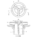
- FIG. 3A is a plan view of the vicinity of the suction port in the magnet pump according to the second embodiment.
- FIG. 3B is a cross-sectional view taken along line A-A ′ of FIG.
- curved portions 40 and 41 that smoothly connect the support leg 7 and the shaft support 6 are formed at the connection portion between the support leg 7 and the shaft support 6.
- the curved portion 40 located on one side in the circumferential direction of the shaft support 6 and the curved portion 41 located on the other side have different curvatures.
- the curvature of the curved portion 40 on one side is gradually increased from the shaft support 6 toward the inner wall of the suction port 4.
- the curvature of the curved portion 40 on one side is formed so as to change from the central portion of the suction port 4 toward the peripheral portion.
- the shape of the curved portions 40 and 41 as described above gives a predetermined swirl to the transfer fluid introduced from the suction port 4 to the impeller 13 in advance. Thereby, introduction of the transfer fluid from the suction port 4 to the impeller 13 becomes smoother than in the first embodiment.
- FIG. 5 is a graph showing a result of comparison of the suction characteristics of the magnet pump between the comparison form, the first embodiment, and the second embodiment.
- NPSH Network (Positive Suction Head: effective suction head)
- NPSHr Required NPSH: required suction head
- the horizontal axis of the graph represents the discharge amount [L / min] of the transfer fluid
- the vertical axis represents the value [m] of NPSHr.
- the value of NPSHr is the largest in the comparative form, and subsequently decreases in the order of the first embodiment and the second embodiment.
- the suction characteristic of a pump is improving compared with a comparison form.
- the suction characteristics of a pump are improving 2nd Embodiment compared with 1st Embodiment.
- FIG. 6 (a) to 6 (c) are graphs showing the results of comparison between the comparison form, the first embodiment, and the second embodiment regarding the pump efficiency of the magnet pump.
- the horizontal axis of the graph represents the flow rate [L / min] of the transfer fluid
- the vertical axis of FIG. 6A represents the total lift (H) [m]
- the vertical axis of FIG. 6B represents the shaft power (SP) [ kW]
- the vertical axis of FIG. 6C represents pump efficiency ( ⁇ ) [%].
- the shaft power (SP) is in the order of the comparative form, the first embodiment, and the second embodiment from the largest.
- the pump efficiency ( ⁇ ) is in the order of the second embodiment, the first embodiment, and the comparative embodiment from the largest.
- the support leg 7 has three suction ports 4 as an example, but the number of support legs 7 is not limited to this, and a plurality of support legs 7 may be used. Any number may be used.
- the magnet pump has been described as an example. However, the improvement of the suction port 4 according to the above embodiment can be applied to other types of pumps.
- FIG. 4A is a plan view of the vicinity of the suction port 4, and FIG. 4B is a cross-sectional view taken along the line BB ′ of FIG. 4A, both corresponding to the third embodiment.
- the three support legs 7 extend substantially linearly from the shaft support 6 positioned at the center of the suction port 4 toward the inner wall of the suction port 4.
- each support leg 7 is formed to be inclined at a predetermined angle ( ⁇ ) with respect to a plane passing through the central axis (see reference numeral 32) of the shaft support 6. . Thereby, a pre-turn can be given to the transfer fluid from the suction port 4 to the impeller 13.
- the magnet pump of the third embodiment it is possible to suppress the generation of turbulent flow and efficiently rectify the transfer fluid.
- SYMBOLS 1 Front casing, 2 ... Rear casing, 3 ... Pump chamber, 4 ... Intake port, 5 ... Discharge port, 6 ... Shaft support body, 7 ... Support leg, 8 ... Cylindrical space, 9 ... Support shaft, 10 ... Tip 11, rotating body, 12, magnet can, 13, impeller, 14, rotating bearing, 15, driven magnet, 16, driving rotating body, 17, driving magnet, 18, driving body casing, 19, rotating shaft, 30,. The tip of the shaft support, 31... The connection between the support leg and the inner wall of the suction port, 32...
Landscapes
- Engineering & Computer Science (AREA)
- Mechanical Engineering (AREA)
- General Engineering & Computer Science (AREA)
- Structures Of Non-Positive Displacement Pumps (AREA)
Abstract
Description
図1は、本発明の第1の実施形態に係るマグネットポンプの断面模式図である。マグネットポンプは、フロントケーシング1と、これに接続されたリアケーシング2とを備える。
第2の実施形態は、移送流体がインペラ13に流入する前に、予め旋回を与える構成を付加した例である。
図4(a)は吸入口4付近の平面図であり、図4(b)は図4(a)のB-B’線に沿った断面図であり、共に第3の実施形態に対応するものである。図4(a)に示すように、3本の支持脚7は、吸入口4の中心に位置する軸支持体6から、約吸入口4の内壁に向かって略直線に延在している。また、図4(b)に示すように、各支持脚7は、軸支持体6の中心軸(符号32参照)を通る平面に対し、所定の角度(θ)をもって傾斜して形成されている。これにより、吸入口4からインペラ13へ至る移送流体に、予旋回を与えることができる。
以上、本発明のいくつかの実施形態を説明したが、これらの実施形態は、例として提示したものであり、発明の範囲を限定することは意図していない。これらの新規な実施形態は、その他の様々な形態で実施されることが可能であり、発明の要旨を逸脱しない範囲で、種々の省略、置き換え、変更を行うことができる。これら実施形態やその変形は、発明の範囲や要旨に含まれるとともに、特許請求の範囲に記載された発明とその均等の範囲に含まれる。
Claims (4)
- 内部にポンプ室が形成されると共に、前記ポンプ室に移送流体を吸入する円筒状の吸入口が設けられたフロントケーシングと、
前記ポンプ室に続く空間を形成するリアケーシングと、
前記空間に配置され、先端部が前記ポンプ室を介して前記吸入口まで延在する支持軸と、
前記空間に配置され、前記支持軸に回転可能に支持され、前記支持軸の周方向に沿ってマグネットが設けられたマグネットキャンと、
前記マグネットキャンに固定され、前記マグネットキャンと一体で回転するように前記ポンプ室に収容されたインペラと、
前記リアケーシングを介して前記マグネットと磁気結合され、前記マグネットに回転駆動力を与える回転駆動手段と、を備え、
前記フロントケーシングは、
前記支持軸の先端を支持する軸支持体と、
前記軸支持体から前記吸入口の内壁に向かって延在し、前記軸支持体を前記吸入口に支持する複数の支持脚と、を含み、
前記軸支持体の先端は、前記吸入口の内壁と前記支持脚との接続部分よりも、前記吸入口の入口側に位置することを特徴とするマグネットポンプ。 - 前記複数の支持脚と前記軸支持体との接続部に両者を滑らかに接続する湾曲部を有し、前記複数の支持脚のそれぞれにおいて、前記軸支持体の周方向の一方の側に位置する前記湾曲部と、他方の側に位置する前記湾曲部とは、曲率が異なることを特徴とする請求項1に記載のマグネットポンプ。
- 前記軸支持体の周方向の一方の側に位置する前記湾曲部は、曲率が前記吸入口の中心部から周辺部に向かって変化するように形成されていることを特徴とする請求項2に記載のマグネットポンプ。
- 前記複数の支持脚は、前記軸支持体の中心軸を通る平面に対し、所定の角度をもって傾斜していることを特徴とする請求項1~3のいずれか1項に記載のマグネットポンプ。
Priority Applications (9)
| Application Number | Priority Date | Filing Date | Title |
|---|---|---|---|
| EP19198539.9A EP3620657A1 (en) | 2013-12-27 | 2013-12-27 | Magnetic pump |
| CN201380081900.7A CN105917121B (zh) | 2013-12-27 | 2013-12-27 | 磁泵 |
| US15/108,424 US10890190B2 (en) | 2013-12-27 | 2013-12-27 | Magnetic pump |
| EP13900453.5A EP3088739B1 (en) | 2013-12-27 | 2013-12-27 | Magnetic pump |
| JP2015554435A JP6324999B2 (ja) | 2013-12-27 | 2013-12-27 | マグネットポンプ |
| PCT/JP2013/085074 WO2015097851A1 (ja) | 2013-12-27 | 2013-12-27 | マグネットポンプ |
| KR1020167020459A KR102118500B1 (ko) | 2013-12-27 | 2013-12-27 | 마그넷 펌프 |
| TW103101415A TWI650485B (zh) | 2013-12-27 | 2014-01-15 | 磁泵 |
| CN201420060745.2U CN204003610U (zh) | 2013-12-27 | 2014-02-10 | 泵用前壳 |
Applications Claiming Priority (1)
| Application Number | Priority Date | Filing Date | Title |
|---|---|---|---|
| PCT/JP2013/085074 WO2015097851A1 (ja) | 2013-12-27 | 2013-12-27 | マグネットポンプ |
Publications (1)
| Publication Number | Publication Date |
|---|---|
| WO2015097851A1 true WO2015097851A1 (ja) | 2015-07-02 |
Family
ID=52043617
Family Applications (1)
| Application Number | Title | Priority Date | Filing Date |
|---|---|---|---|
| PCT/JP2013/085074 Ceased WO2015097851A1 (ja) | 2013-12-27 | 2013-12-27 | マグネットポンプ |
Country Status (7)
| Country | Link |
|---|---|
| US (1) | US10890190B2 (ja) |
| EP (2) | EP3088739B1 (ja) |
| JP (1) | JP6324999B2 (ja) |
| KR (1) | KR102118500B1 (ja) |
| CN (2) | CN105917121B (ja) |
| TW (1) | TWI650485B (ja) |
| WO (1) | WO2015097851A1 (ja) |
Cited By (2)
| Publication number | Priority date | Publication date | Assignee | Title |
|---|---|---|---|---|
| EP3176439A3 (en) * | 2015-11-12 | 2017-10-11 | Panasonic Intellectual Property Management Co., Ltd. | Centrifugal pump with a volute having a slanted wall |
| WO2021261425A1 (ja) | 2020-06-22 | 2021-12-30 | 株式会社ウスイテクノス | 動力発生装置 |
Families Citing this family (6)
| Publication number | Priority date | Publication date | Assignee | Title |
|---|---|---|---|---|
| CN105179256B (zh) * | 2015-08-07 | 2017-12-19 | 北京控制工程研究所 | 一种空间在轨加注用循环加注泵 |
| JP6624962B2 (ja) * | 2016-02-10 | 2019-12-25 | 株式会社荏原製作所 | 多段水中ポンプ用の吸込ケーシング、および、多段水中ポンプ |
| CN110944690B (zh) | 2018-07-24 | 2022-04-08 | 卡迪亚卡西斯特股份有限公司 | 旋转式血液泵 |
| WO2020179985A1 (ko) * | 2019-03-06 | 2020-09-10 | (주)플로닉스 | 펌프 케이싱 및 이를 포함하는 마그넷 펌프 |
| KR102222303B1 (ko) * | 2019-04-04 | 2021-03-03 | (주)플로닉스 | 유체 가이드 장치 및 이를 포함하는 마그넷 펌프 |
| JP7381418B2 (ja) | 2020-07-20 | 2023-11-15 | 株式会社ワールドケミカル | マグネットポンプ及びマグネットポンプ用回転体 |
Citations (5)
| Publication number | Priority date | Publication date | Assignee | Title |
|---|---|---|---|---|
| JPH0617785A (ja) * | 1992-02-18 | 1994-01-25 | Ouken Seiko Kk | インペラーポンプ |
| JPH08277795A (ja) * | 1995-04-05 | 1996-10-22 | Matsushita Electric Ind Co Ltd | 遠心ポンプ |
| JPH10201626A (ja) * | 1997-01-28 | 1998-08-04 | Matsushita Electric Works Ltd | 電動ポット用のポンプ |
| WO2001012993A1 (en) | 1999-08-10 | 2001-02-22 | Iwaki Co., Ltd. | Magnet pump |
| JP2013096406A (ja) * | 2011-11-03 | 2013-05-20 | Assoma Inc | 磁気駆動ポンプ |
Family Cites Families (10)
| Publication number | Priority date | Publication date | Assignee | Title |
|---|---|---|---|---|
| US4637779A (en) * | 1985-05-17 | 1987-01-20 | Kamyr, Inc. | Two stage medium consistency pulp pumping |
| US4722661A (en) | 1985-10-09 | 1988-02-02 | Ngk Insulators, Ltd. | Magnetic-drive centrifugal pump |
| DE4305023C2 (de) | 1992-02-18 | 1999-08-19 | Oken Seiko Kk | Flügelradpumpe |
| US5399074A (en) | 1992-09-04 | 1995-03-21 | Kyocera Corporation | Motor driven sealless blood pump |
| DE4321260C1 (de) | 1993-06-25 | 1995-03-09 | Westphal Dieter Dipl Ing Dipl | Blutpumpe als Zentrifugalpumpe |
| US5895203A (en) * | 1996-04-15 | 1999-04-20 | Ansimag Incorporated | Centrifugal pump having separable, multipartite impeller assembly |
| JP2001165085A (ja) | 1999-12-06 | 2001-06-19 | Tokyo Kousou Kk | マグネットポンプ |
| US9909588B2 (en) * | 2010-07-30 | 2018-03-06 | The Board Of Regents Of The University Of Texas System | Axial-flow pumps and related methods |
| DE102011107557A1 (de) * | 2011-07-16 | 2013-01-17 | Volkswagen Aktiengesellschaft | Strömungspumpe |
| CN202510426U (zh) | 2012-01-04 | 2012-10-31 | 大连海密梯克泵业有限公司 | 大功率高温磁力驱动泵 |
-
2013
- 2013-12-27 WO PCT/JP2013/085074 patent/WO2015097851A1/ja not_active Ceased
- 2013-12-27 KR KR1020167020459A patent/KR102118500B1/ko active Active
- 2013-12-27 US US15/108,424 patent/US10890190B2/en active Active
- 2013-12-27 EP EP13900453.5A patent/EP3088739B1/en active Active
- 2013-12-27 CN CN201380081900.7A patent/CN105917121B/zh active Active
- 2013-12-27 JP JP2015554435A patent/JP6324999B2/ja active Active
- 2013-12-27 EP EP19198539.9A patent/EP3620657A1/en not_active Withdrawn
-
2014
- 2014-01-15 TW TW103101415A patent/TWI650485B/zh not_active IP Right Cessation
- 2014-02-10 CN CN201420060745.2U patent/CN204003610U/zh not_active Expired - Fee Related
Patent Citations (5)
| Publication number | Priority date | Publication date | Assignee | Title |
|---|---|---|---|---|
| JPH0617785A (ja) * | 1992-02-18 | 1994-01-25 | Ouken Seiko Kk | インペラーポンプ |
| JPH08277795A (ja) * | 1995-04-05 | 1996-10-22 | Matsushita Electric Ind Co Ltd | 遠心ポンプ |
| JPH10201626A (ja) * | 1997-01-28 | 1998-08-04 | Matsushita Electric Works Ltd | 電動ポット用のポンプ |
| WO2001012993A1 (en) | 1999-08-10 | 2001-02-22 | Iwaki Co., Ltd. | Magnet pump |
| JP2013096406A (ja) * | 2011-11-03 | 2013-05-20 | Assoma Inc | 磁気駆動ポンプ |
Non-Patent Citations (1)
| Title |
|---|
| See also references of EP3088739A4 |
Cited By (2)
| Publication number | Priority date | Publication date | Assignee | Title |
|---|---|---|---|---|
| EP3176439A3 (en) * | 2015-11-12 | 2017-10-11 | Panasonic Intellectual Property Management Co., Ltd. | Centrifugal pump with a volute having a slanted wall |
| WO2021261425A1 (ja) | 2020-06-22 | 2021-12-30 | 株式会社ウスイテクノス | 動力発生装置 |
Also Published As
| Publication number | Publication date |
|---|---|
| CN105917121A (zh) | 2016-08-31 |
| US20160341201A1 (en) | 2016-11-24 |
| CN105917121B (zh) | 2019-01-01 |
| CN204003610U (zh) | 2014-12-10 |
| TWI650485B (zh) | 2019-02-11 |
| EP3088739A4 (en) | 2017-01-11 |
| KR102118500B1 (ko) | 2020-06-03 |
| JPWO2015097851A1 (ja) | 2017-03-23 |
| US10890190B2 (en) | 2021-01-12 |
| EP3088739A1 (en) | 2016-11-02 |
| KR20160122707A (ko) | 2016-10-24 |
| EP3088739B1 (en) | 2019-11-06 |
| TW201525291A (zh) | 2015-07-01 |
| EP3620657A1 (en) | 2020-03-11 |
| JP6324999B2 (ja) | 2018-05-16 |
Similar Documents
| Publication | Publication Date | Title |
|---|---|---|
| JP6324999B2 (ja) | マグネットポンプ | |
| TWI702340B (zh) | 軸流送風機及串聯型軸流送風機 | |
| JP6390272B2 (ja) | インペラ、及び送風機 | |
| JPWO2016068280A1 (ja) | 送風装置および掃除機 | |
| CN106062380B (zh) | 送风装置 | |
| CN104514737A (zh) | 通风结构 | |
| WO2014199498A1 (ja) | インペラ及び流体機械 | |
| US20160153457A1 (en) | Fan assembly for centrifugal blower and air conditioning apparatus including the same | |
| JP2013185440A (ja) | 遠心ファン | |
| JP2010019251A (ja) | インペラおよび遠心ファン | |
| JP5907205B2 (ja) | 送風装置 | |
| CN103790837A (zh) | 轴流式永磁电机水泵 | |
| CN108506246B (zh) | 轴流风轮、空调室外机及空调器 | |
| CN108603507B (zh) | 多段潜水泵用的吸入外壳、以及多段潜水泵 | |
| CN215170729U (zh) | 一种自吸半离心式抽水泵 | |
| KR20150137483A (ko) | 에어포일 형상의 후향깃 원심임펠러 | |
| CN205371071U (zh) | 新型联体定叶轮及电机后壳组件 | |
| JP5795217B2 (ja) | 流体ポンプ | |
| WO2016026364A1 (zh) | 由电机驱动的转动部件、电机及风机 | |
| JP2015135118A (ja) | 送風装置 | |
| CN205101222U (zh) | 一体电动泵 | |
| JP2015129482A (ja) | シロッコ型遠心送風機 | |
| JP6258757B2 (ja) | 電動ウォータポンプ | |
| KR101567534B1 (ko) | 유체가이드가 형성된 흡입하우징을 가지는 펌프 | |
| JP2006307814A (ja) | ポンプ |
Legal Events
| Date | Code | Title | Description |
|---|---|---|---|
| REEP | Request for entry into the european phase |
Ref document number: 2013900453 Country of ref document: EP |
|
| WWE | Wipo information: entry into national phase |
Ref document number: 2013900453 Country of ref document: EP |
|
| 121 | Ep: the epo has been informed by wipo that ep was designated in this application |
Ref document number: 13900453 Country of ref document: EP Kind code of ref document: A1 |
|
| ENP | Entry into the national phase |
Ref document number: 2015554435 Country of ref document: JP Kind code of ref document: A |
|
| NENP | Non-entry into the national phase |
Ref country code: DE |
|
| WWE | Wipo information: entry into national phase |
Ref document number: 15108424 Country of ref document: US |
|
| ENP | Entry into the national phase |
Ref document number: 20167020459 Country of ref document: KR Kind code of ref document: A |