WO2015098029A1 - 無線通信装置、無線通信ネットワーク、識別番号設定方法 - Google Patents
無線通信装置、無線通信ネットワーク、識別番号設定方法 Download PDFInfo
- Publication number
- WO2015098029A1 WO2015098029A1 PCT/JP2014/006214 JP2014006214W WO2015098029A1 WO 2015098029 A1 WO2015098029 A1 WO 2015098029A1 JP 2014006214 W JP2014006214 W JP 2014006214W WO 2015098029 A1 WO2015098029 A1 WO 2015098029A1
- Authority
- WO
- WIPO (PCT)
- Prior art keywords
- wireless communication
- network
- communication device
- address
- unit
- Prior art date
- Legal status (The legal status is an assumption and is not a legal conclusion. Google has not performed a legal analysis and makes no representation as to the accuracy of the status listed.)
- Ceased
Links
Images



Classifications
-
- H—ELECTRICITY
- H04—ELECTRIC COMMUNICATION TECHNIQUE
- H04W—WIRELESS COMMUNICATION NETWORKS
- H04W8/00—Network data management
- H04W8/26—Network addressing or numbering for mobility support
-
- H—ELECTRICITY
- H04—ELECTRIC COMMUNICATION TECHNIQUE
- H04L—TRANSMISSION OF DIGITAL INFORMATION, e.g. TELEGRAPHIC COMMUNICATION
- H04L61/00—Network arrangements, protocols or services for addressing or naming
- H04L61/50—Address allocation
- H04L61/5007—Internet protocol [IP] addresses
- H04L61/5014—Internet protocol [IP] addresses using dynamic host configuration protocol [DHCP] or bootstrap protocol [BOOTP]
-
- H—ELECTRICITY
- H04—ELECTRIC COMMUNICATION TECHNIQUE
- H04W—WIRELESS COMMUNICATION NETWORKS
- H04W76/00—Connection management
- H04W76/10—Connection setup
- H04W76/14—Direct-mode setup
-
- H—ELECTRICITY
- H04—ELECTRIC COMMUNICATION TECHNIQUE
- H04W—WIRELESS COMMUNICATION NETWORKS
- H04W80/00—Wireless network protocols or protocol adaptations to wireless operation
- H04W80/04—Network layer protocols, e.g. mobile IP [Internet Protocol]
Definitions
- the present invention relates to a wireless communication device, a wireless communication network, and an identification number setting method, and more particularly to a wireless communication device, a wireless communication network, and an identification number setting method for assigning an IP address to devices constituting the network.
- a DHCP server is installed in a network in order to assign an IP (Internet Protocol) address to each wireless communication device constituting the network.
- IP Internet Protocol
- DHCP is an abbreviation for Dynamic Host Configuration Protocol.
- Patent Document 1 is disclosed as a wireless communication network in which a DHCP server is installed.
- FIG. 11 is a configuration diagram of a wireless communication network disclosed in Patent Document 1.
- the wireless communication network of Patent Document 1 includes a router 501, a wireless LAN access point terminal 502, and wireless LAN terminals 503-1, 503-2, and 503-3.
- LAN is an abbreviation for Local Area Network.
- the wireless LAN terminals 503-1, 503-2, and 503-3 are connected to the router 501 via the wireless LAN 506, that is, a wireless line or the like.
- the router 501 includes a DHCP server 504.
- the DHCP server 504 of the router 501 assigns IP addresses to the wireless LAN access point terminal 502 and the wireless LAN terminals 503-1, 503-2, and 503-3.
- the wireless LAN terminals 503-1, 503-2, and 503-3 include DHCP client function units 505-1, 505-2, and 505-3, and acquire an IP address from the DHCP server 504.
- the wireless LAN terminals 503-1, 503-2, and 503-3 communicate with an external network through the wireless LAN access point terminal 502 and the router 501 using the acquired IP address.
- the DHCP server automatically assigns IP addresses to the wireless terminals 503-1, 503-2, and 503-3.
- each of the wireless terminals 503-1, 503-2, and 503-3 can communicate with an external network via the wireless LAN access point terminal 502 and the router 501.
- a communication network in which a DHCP server is installed is also disclosed in Patent Document 2 below.
- the DHCP server of the communication network of Patent Document 2 stores in advance an IP address that does not overlap with other DHCP server devices.
- the stored IP address is stored in the client terminal. assign.
- the communication network of Patent Document 2 can prevent the same IP address from being set redundantly in the client terminal.
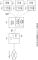
- FIG. 12 is a diagram illustrating a configuration example of a general wireless communication network including a wireless communication device that performs wireless communication point-to-point with an adjacent wireless communication device.
- the above-described wireless communication network does not require a cable to be laid between wireless communication apparatuses that perform point-to-point wireless communication. Therefore, it is possible to construct a network by reducing the introduction cost.
- a network including a wireless communication device that performs point-to-point wireless communication needs to separately provide a DHCP server in order to assign an IP address to each wireless communication device, as in the communication networks of Patent Documents 1 and 2. was there. Since it is necessary to provide a DHCP server separately, the network including the wireless communication device that performs the above-described point-to-point wireless communication (hereinafter referred to as “P2P communication network”) can sufficiently suppress the network introduction cost. There was a problem that not.
- the P2P communication network generally includes one DHCP server, and one DHCP server assigns an IP address to each wireless communication device. Therefore, in the P2P communication network, the DHCP server assigns an IP address to each wireless communication device via many wireless lines. For example, in the case of the P2P communication network shown in FIG. 13, the DHCP server assigns an IP address to the wireless communication apparatus 513 via the two wireless lines 520 and 521.
- the P2P communication network that assigns the IP address via many wireless lines has a problem that a wireless communication device to which no IP address is assigned is likely to occur.
- the DHCP server assigns an IP address to the wireless communication apparatus 513 via the plurality of wireless lines 520 and 521, but the IP address cannot be assigned to the wireless communication apparatus 513 only by deterioration of one of the wireless lines 520 and 521. .
- a wireless communication device to which an IP address is not assigned is likely to occur.
- the more the number of wireless lines between the DHCP server and each wireless communication device the more the above-described problem occurs.
- a wireless communication device of the present invention is a wireless communication device that performs point-to-point wireless communication with at least one of other communication devices, and when a predetermined signal is input, A predetermined identification number is assigned to another communication device.
- a wireless communication network of the present invention is a wireless communication device that performs point-to-point wireless communication with at least one of other communication devices, and when a predetermined signal is input, A wireless communication device that assigns a predetermined identification number to another communication device is provided.
- an identification number setting method of the present invention is an identification number setting method for wireless communication means for performing point-to-point wireless communication with at least one of other communication means, wherein a predetermined signal is When input, a predetermined identification number is assigned to the other communication means.
- the wireless communication network can sufficiently suppress the network introduction cost.
- FIG. 6 is a diagram (No. 1) for explaining the operation of the wireless communication device provided in the wireless communication network according to the first embodiment of the present invention
- FIG. 6 is a diagram (No. 2) for explaining the operation of the wireless communication apparatus included in the wireless communication network according to the first embodiment of the present invention.
- FIG. 6 shows the other structural example (when each radio
- FIG. 1 is a configuration diagram of a wireless communication network of Patent Document 1.
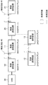
- FIG. It is a figure which shows the structural example of the general radio
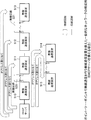
- FIG. 1 is a diagram illustrating a configuration example of a wireless communication network according to the first embodiment of the present invention.
- the wireless communication network according to the first embodiment of the present invention includes wireless communication devices 10 to 13 and 20 to 21 that perform point-to-point wireless communication with adjacent wireless communication devices. It is a network provided with. That is, the wireless communication network of this embodiment is a P2P communication network.
- the wireless communication network of the present embodiment includes a plurality of wireless communication devices 10 and 20 having a DHCP server function. Since the wireless communication devices 10 and 20 have the function of a DHCP server, the wireless communication network of this embodiment does not require a separate DHCP server, and the introduction cost of the network can be sufficiently suppressed.
- the wireless communication devices 10 and 20 having a DHCP server function are arranged via at least one wireless line (in the case of FIG. 1, the wireless line 40).
- the wireless communication device 10 and the wireless communication device 20 are connected in series with at least one other wireless communication device (for example, the wireless communication device 21).
- this wireless communication network determines the number of wireless lines between the DHCP wireless communication device and each wireless communication device. It can be reduced from a general P2P communication network.
- the number of wireless lines between the DHCP server and the wireless communication device 513 is two.
- the wireless line between the DHCP wireless communication apparatus and the wireless communication apparatus 21 (corresponding to the wireless communication apparatus 513) is reduced to one of the wireless lines 41.
- the wireless communication network of the present embodiment may make it difficult to generate a wireless communication device to which no IP address is assigned. it can.
- the DHCP wireless communication device is assigned a predetermined wireless communication device in charge so that a plurality of DHCP wireless communication devices do not overlap and assign an IP address to one wireless communication device. Allocation is performed only when the request is accepted.
- the above-described request is a request for IP address assignment.
- the radio communication network of the present embodiment includes radio communication devices 10, 11, 12, 13, 20, 21, and And EMS (Element Management System) 30.
- the wireless communication device 10 and the wireless communication device 20 are connected to each other via the wireless line 40 and the wireless communication device 11. Specifically, the wireless communication device 10 is connected to the wireless communication device 11 via a wireless line 40, and the wireless communication device 11 is connected to the wireless communication device 20 via a wired line. Further, the wireless communication device 20 is connected to the wireless communication device 21 via a wireless line. The wireless communication device 20 is connected to the wireless communication device 13 via a wired line. The wireless communication device 13 is connected to the wireless communication device 12 via a wireless line. The wireless communication device 10 is also connected to the EMS 30 via a wired line.
- the wireless communication devices 10 and 20 have a function of performing wireless communication with adjacent wireless communication devices 11 and 21 in a point-to-point manner.
- the wireless communication devices 10 and 20 have a DHCP server function, and when an IP address is requested from the wireless communication devices 11 to 13 and 21, an IP address is assigned to the wireless communication device.
- the wireless communication devices 10 and 20 are determined to be the predetermined devices in charge of the wireless communication device that has requested the IP address assignment so that both do not assign the IP address to the wireless communication device 11 or the like.
- an IP address is assigned. The method of determining whether the device is a predetermined device will be described in detail in [Description of operation] described later.
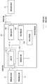
- FIG. 2 is a diagram illustrating a configuration example of the wireless communication device 20 provided in the wireless communication network according to the first embodiment of the present invention.
- the allocation function unit 103 is connected to the communication unit 101-1, the communication unit 101-2, the wireless communication unit 102, the allocation grasping unit 104, and the information holding unit 105.
- the information holding unit 105 is connected to the communication unit 101-1, the communication unit 101-2, and the allocation grasping unit 104.
- the communication unit 101-1 is connected to the wireless communication device 11 via a wired line.
- the communication unit 101-2 is connected to the wireless communication device 13 via a wired line.
- the wireless communication unit 102 is connected to the wireless communication device 21 via a wireless line.
- the communication unit 101-1, the communication unit 101-2, and the wireless communication unit 102 can be realized using an electronic circuit, an FPGA (Field-Programmable Gate Array), or a DSP (Digital Signal Processor).
- the allocation function unit 103, the allocation grasping unit 104, and the information holding unit 105 can be realized by software, and include a CPU (Central Processing Unit) and a memory such as a RAM for operating the software. RAM is an abbreviation for Random Access Memory.
- the communication unit 101-i When a packet requesting IP address assignment (hereinafter referred to as “assignment request packet”) is input from the connected wired line, the communication unit 101-i outputs the assignment request packet to the assignment function unit 103. . The communication unit 101-i outputs the packet input from the assignment function unit 103 to the wired line.
- assignment request packet a packet requesting IP address assignment
- the wireless communication unit 102 executes the following functions after establishing a point-to-point connection with an adjacent wireless communication device after activation.
- the wireless communication unit 102 when an assignment request packet is input from a connected wireless line (that is, an adjacent wireless communication device), the wireless communication unit 102 outputs the assignment request packet to the assignment function unit 103. Further, the wireless communication unit 102 outputs the packet input from the assignment function unit 103 as a wireless signal to the connected wireless line (adjacent wireless communication device).
- the allocation function unit 103 determines whether or not the input packet is an allocation request packet from a predetermined wireless communication device in charge. Details of the above-described determination method will be described in [Description of operation] described later.
- the allocation function unit 103 When the input function unit 103 determines that the input packet is an allocation request packet from a predetermined wireless communication device, the allocation function unit 103 requests the information holding unit 105 for an assignable IP address. When an assignable IP address is input, the assignment function unit 103 arbitrarily selects one IP address from the IP addresses, the communication unit 101-i that has input the assignment request packet using the selected IP address as a packet, Alternatively, the data is output to the wireless communication unit 102. Note that, when outputting a packet, the allocation function unit 103 extracts a MAC address from the input allocation request packet, and outputs the destination MAC (Media Access Control) address of the output packet as the extracted MAC address. Further, the allocation function unit 103 outputs the selected IP address to the allocation grasping unit 104.
- the assignment function unit 103 When an assignable IP address is input, the assignment function unit 103 arbitrarily selects one IP address from the IP addresses, the communication unit 101-i that has input the assignment request packet using the selected IP address as a packet
- the allocation function unit 103 determines that the input packet is not an allocation request packet from a predetermined wireless communication device, the allocation function unit 103 transfers the input allocation request packet to another wireless communication device. Details of the transfer method will be described later in [Description of operation].
- the allocation grasping unit 104 When the IP address is input, the allocation grasping unit 104 outputs a signal requesting not to allocate the IP address (hereinafter referred to as “allocation impossible signal”). The allocation grasping unit 104 outputs the above-described allocation impossible signal including the input IP address.
- the information holding unit 105 sets and holds at least one IP address that can be used in the network by the administrator of the wireless communication network of the present embodiment.
- the information holding unit 105 When the information holding unit 105 is requested for an assignable IP address, the information holding unit 105 outputs the holdable IP address.
- the information holding unit 105 extracts an IP address from the signal, deletes the extracted IP address from the holdable assignable IP address, and assigns the assigned IP address.
- Wireless communication devices 11, 12, 13, and 21 perform point-to-point wireless communication with adjacent wireless communication devices 10, 13, 12, and 20. And a general DHCP client function.
- the wireless communication devices 11, 12, 13, and 21 are connected to the adjacent wireless communication devices 10, 13, 12, and 20 (in the case of the wireless communication devices 10 and 20, the wireless communication of the wireless communication devices 10 and 20).
- the following functions are executed after a point-to-point connection is established with the unit 102).
- the wireless communication apparatuses 11, 12, 13, and 21 broadcast a packet for requesting IP address assignment, that is, an assignment request packet in the wireless communication network of the present embodiment.
- the allocation request packet may be a known broadcast packet.
- the wireless communication apparatuses 11, 12, 13, and 21 broadcast the allocation request packet including its own MAC address.
- the wireless communication apparatuses 11, 12, 13, and 21 receive the assignment request packet from the other wireless communication apparatuses 10 to 13, 20 Output to ⁇ 21.
- the wireless communication devices 11, 12, 13, and 21 extract an IP address from the packet.
- the wireless communication apparatuses 11, 12, 13, and 21 hold the extracted IP address as their own IP address.
- the EMS 30 is a general EMS and monitors each wireless communication device.
- An IP address is set in the EMS 30 by the administrator of the wireless communication network of the present embodiment.
- the EMS 30 holds the set IP address as its own IP address.
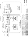
- FIGS. 3 and 4 are diagrams for explaining the operation of the wireless communication apparatus provided in the wireless communication network according to the first embodiment of the present invention. The operation of the wireless communication apparatus according to the present embodiment will be described below with reference to FIGS.
- DHCP server Prior setting to wireless communication devices 10 and 20 (DHCP server) (1-1) Determination of wireless communication device to assign IP address First, when operating the wireless communication network of the present embodiment, the present embodiment The wireless communication network administrator determines a wireless communication device that forms a network with the wireless communication devices 10 and 20 for each of the wireless communication devices 10 and 20 having the DHCP server function.
- the administrator of this wireless communication network uses the wireless communication devices 11 to 13 as the wireless communication devices that form a network with the wireless communication device 10 and the wireless communication device 21 as the wireless communication device that forms a network with the wireless communication device 20. You may decide that there is.
- network 1 the network formed by the wireless communication device 10 and the wireless communication devices 11 to 13
- network 2 the network formed by the wireless communication device 20 and the wireless communication device 21
- Wireless communication devices 10 and 20 are wireless communication devices that form a network with themselves (described above). The operation of assigning an IP address to (the wireless communication device determined in “(1-1)”) is performed. In order to realize the above-described operation, the administrator of the wireless communication network according to the present embodiment performs the following (1-2-1) to (1-2) on the wireless communication apparatuses 10 and 20 having the DHCP server function. -3) Set in advance.
- the administrator of the wireless communication network of the present embodiment communicates with the allocation function unit 103 of each of the wireless communication devices 10 and 20 in the wireless communication devices 10 and 20.
- the IP address of the unit 101-i and the wireless communication unit 102 (hereinafter referred to as “port”) is set.
- the administrator of the wireless communication network sends the IP address of each port of the wireless communication device 10 to the allocation function unit 103 of the wireless communication device 10, that is, the communication unit included in the wireless communication device 10.
- the IP addresses of 101-1 and the wireless communication unit 102 are set.
- the administrator makes the assignment function unit 103 of the wireless communication device 20 have an IP address of each port of the wireless communication device 20, that is, the communication unit 101-1, the communication unit 101-2, and the wireless communication of the wireless communication device 20.
- the IP address of the unit 102 is set.
- the administrator of the wireless communication network of this embodiment may set an arbitrary IP address as the IP address of each port.
- the IP addresses of the ports for example, the wireless communication unit 102 of the wireless communication device 10
- all are network units (for example, “172” representing the network 1). 18.1 ") IP address.
- the administrator represents the network unit representing the network 2 (for example, “172.18.2”). ) Is set.
- the network units representing the networks 1 and 2 are determined by the administrator of the wireless communication network of the present embodiment so as to be different from each other.
- FIG. 1 A specific example of setting the IP address of each port is shown in FIG.
- the administrator of the wireless communication network of this embodiment may set the IP address of each port as described in association with the letters “A” to “E” in FIG.
- the administrator of the wireless communication network can assign the information holding unit 105 of the wireless communication devices 10 and 20 to each wireless communication device.
- Each IP address is set.
- the administrator of the wireless communication network of the present embodiment can assign the IP address of the network unit representing the network 1 to the wireless communication devices 11 to 13 to the information holding unit 105 of the wireless communication device 10. Set as address.
- the administrator of the wireless communication network of the present embodiment sets the IP address of the network unit representing the network 2 as an IP address that can be assigned to the wireless communication device 21 for the information holding unit 105 of the wireless communication device 20. .
- the information holding unit 105 of the wireless communication devices 10 and 20 holds the set assignable IP address.
- IP address For example, the administrator of the wireless communication network of the present embodiment stores “172.18.1.10/24”, “172.18.1.11/24”,... In the information holding unit 105 of the wireless communication device 10. Forty IP addresses of “172.8.1.49/24” may be set. Each IP address is an IP address having a network portion (“172.8.1”) representing the network 1.
- the administrator of the wireless communication network of this embodiment stores “172.18.2.10/24”, “172.18.2.11/24” to “172.18.2.110/24” in the information holding unit 105 of the wireless communication device 20.
- Forty IP addresses of “172.18.2.49/24” may be set.
- Each IP address is an IP address having a network part (“172.18.2”) representing the network 2.
- the administrator of the wireless communication network of the present embodiment sets the IP address of the default gateway for the assignment function unit 103 of the wireless communication devices 10 and 20.
- the administrator of the wireless communication network according to the present embodiment gives the allocation function unit 103 of the wireless communication apparatus 10 an apparatus outside the network 1 connected to the wireless communication apparatus 10, for example, the IP address of the EMS 30. Is set as the IP address of the default gateway.
- the administrator of the wireless communication network according to the present embodiment provides the allocation function unit 103 of the wireless communication device 20 with an IP address of a device outside the network 2 connected to the wireless communication device 20, for example, a port of the wireless communication device 10. Is set as the IP address of the default gateway.
- the administrator of the wireless communication network sends the IP address “172.18” of the communication unit 101-1 of the wireless communication device 10 to the allocation function unit 103 of the wireless communication device 20 as the default gateway IP address. "1.1 / 24" may be set. In FIG. 3, the set IP address “172.18.1.1/24” is described in association with the letter “X”.
- the administrator of the wireless communication network provides the allocation function unit 103 of the wireless communication apparatus 10 with the IP address of the EMS 30 as the default gateway IP address, for example, “172.18.3.1/24”. May be set. In FIG. 3, the set IP address “172.18.3.1.24” is described in association with the letter “Y”.
- each of the wireless communication devices 10 to 13 and 20 to 21 (in the case of the wireless communication devices 10 and 20, the wireless communication unit 102) will start up after the wireless communication devices 11, 10, 13, The description will be made on the assumption that a point-to-point connection has been established with 12, 21, and 20.
- the above-described allocation request packet may be a well-known broadcast packet, for example, a DHCP Discover message.
- the wireless communication devices 11 to 13 and 21 broadcast the allocation request packet including its own MAC (Media Access Control) address.
- Allocation request packets broadcast from the wireless communication devices 11 to 13 and 21 are input to the wireless communication devices 10 and 20.
- the wireless communication device 10 determines whether the assignment request packet is an assignment request packet from the wireless communication devices 11, 12, and 13 that form the network 1 with itself. To do.
- the wireless communication device 20 determines whether the assignment request packet is an assignment request packet from the wireless communication device 21 that forms the network 2 with itself. Details of the determination will be described in the following (details of operation).
- the wireless communication apparatuses 10 and 20 send IP to the wireless communication apparatus that has input the assignment request packet. Assign an address.
- the wireless communication devices 10 and 20 perform the processes shown in S10 to S21 below.
- the following S10 to S21 describe the wireless communication apparatus 20, but the same applies to the case of the wireless communication apparatus 10.
- the wireless communication device 10 has “wireless communication device 20” as “wireless communication device 10”, “network 2” as “network 1”, and “wireless communication device 21” as “wireless communication devices 11-13”. In other words, the following S10 to S21 are performed.
- the allocation function unit 103 of the wireless communication device 20 determines whether the input allocation request packet is an allocation request packet from the wireless communication device 21 forming the network 2. .
- the allocation function unit 103 of the wireless communication device 20 performs the determination as described in (I) to (III) below.
- the assignment function unit 103 of the wireless communication device 20 determines whether the IP address network part of the wireless communication part 102 is the same as the default gateway IP address network part. Determine whether or not.
- the determination of the above (I) is based on whether the wireless communication part 102 that has input the allocation request packet belongs to a network other than the network 2. Is determined.
- the wireless communication part 102 belongs to a network other than the network 2.
- the assignment request packet input from the wireless communication unit 102 is input from a network other than the network 2. That is, if the network part of the IP address of the wireless communication unit 102 is the same as the network part of the IP address of the default gateway, the input assignment request packet is not an assignment request packet from the wireless communication device 21 forming the network 2 Can be determined.
- the wireless communication part 102 belongs to a network other than the network 2 Absent.
- the allocation request packet input from the wireless communication unit 102 is input from the network 2. It will be that. That is, if the network part of the IP address of the wireless communication unit 102 is different from the network part of the IP address of the default gateway, the input assignment request packet can be determined as the assignment request packet from the wireless communication device 21 forming the network 2. .
- the input allocation request packet is regarded as an allocation request packet from the wireless communication device 21 forming the network 2.
- the administrator of the wireless communication network of the present embodiment sets the IP address of the wireless communication unit 102 to the wireless communication device 20 as “ 172.18.2.1/24 ". (See E in FIG. 3.)
- the administrator of the wireless communication network of the present embodiment sets the IP address of the default gateway as “172.18.1.1/24” in the wireless communication apparatus 20. (See X in FIG. 3.) Since the allocation function unit 103 of the wireless communication device 20 is different in the network unit of each IP address described above, the wireless communication device 21 in which the input allocation request packet forms the network 2 by the process (III) described above. It is determined as an allocation request packet from.
- the allocation function unit 103 uses the input allocation request packet as another radio packet. Transfer to communication device. The specific contents of this transfer operation will be described in detail in S22 described later. Hereinafter, the description will be continued assuming that the input allocation request packet is determined as the allocation request packet from the wireless communication device 21 forming the network 2.
- the allocation function unit 103 immediately receives the allocation request packet from the radio communication unit 102 instead of performing the processes (I) to (III) described above, and immediately, the radio communication device 21 that forms the network 2. May be regarded as an allocation request packet from.
- the allocation function unit 103 determines that the input allocation request packet is an allocation request packet from the wireless communication device 21 forming the network 2 (Yes in S11).
- the information holding unit 105 is requested for an assignable IP address. This is for assigning an IP address to the wireless communication device 21.
- the information holding unit 105 of the wireless communication apparatus 20 is set in advance as an assignable IP address and holds “172.18.2.10/24” to “172.18.2. 49/24 "is output to the allocation function unit 103.
- the allocation function unit 103 of the wireless communication apparatus 20 sets the selected IP address as a general packet. At this time, the allocation function unit 103 of the wireless communication device 20 extracts the MAC address from the input allocation request packet, and sets the destination MAC address of the packet as the extracted MAC address.
- the above extracted MAC address is the MAC address of the wireless communication device 21. Therefore, the above packet is a packet addressed to the wireless communication device 21.
- the packet described above may be a well-known DHCP OFFER packet.
- the allocation function unit 103 of the wireless communication device 20 outputs the packet generated in S15 to the wireless communication unit 102 or the communication unit 101-i that has input the allocation request packet.
- the assignment request packet is input to the wireless communication unit 102 as in S10
- the assignment function unit 103 of the wireless communication device 20 outputs the packet generated in S15 to the wireless communication unit 102. To do.
- the wireless communication unit 102 of the wireless communication device 20 outputs the input packet (IP address) to the wireless communication device 21 as a wireless signal.
- the wireless communication device 21 After the above-described S17, the wireless communication device 21 receives a packet from the wireless communication device 20.
- the wireless communication device 21 Since the destination MAC address of the input packet is its own MAC address, the wireless communication device 21 acquires an IP address from the extracted packet. The wireless communication device 21 holds the acquired IP address as its own IP address.
- the wireless communication device 20 assigns an IP address to the wireless communication device 21 by the processes of S12 to S17 described above.
- the wireless communication device 20 performs the following S18 to S20 so as not to assign the IP address assigned to the wireless communication device 21 to other devices. Perform the process shown.
- the allocation function unit 103 of the wireless communication apparatus 20 After the above-described S16, the allocation function unit 103 of the wireless communication apparatus 20 outputs the IP address selected in the above-described S14 to the allocation grasping unit 104.
- allocation impossible signal a signal requesting not to allocate an IP address (hereinafter referred to as “allocation impossible signal”) to the information holding unit.
- allocation grasping unit 104 of the wireless communication apparatus 20 outputs the above-described allocation impossible signal including the input IP address.
- the information holding unit 105 of the wireless communication apparatus 20 extracts the IP address from the signal, and deletes the extracted IP address from the holdable assignable IP address. In addition, the information holding unit 105 of the wireless communication device 20 stores the extracted IP address as an assigned IP address.
- the allocation function unit 103 of the wireless communication device 20 receives the allocation request packet from the wireless communication device 21 that forms the network 2 in the same way as in S11 described above. It is determined whether or not.
- the allocation function unit 103 of the wireless communication device 20 performs the procedures shown in the above (I) to (III). However, the allocation function unit 103 of the wireless communication device 20 reads the “wireless communication unit 102” as “communication unit 101-i” and performs the procedures shown in the above (I) to (III).
- the administrator of the wireless communication network of the present embodiment as shown in FIG. An IP address “172.18.1” is set in the allocation function unit 103.
- the administrator of the wireless communication network according to the present embodiment sets an IP address whose network unit is “172.8.1” in the assignment function unit 103 as the IP address of the default gateway.
- the above two IP addresses have the same network part. Since it is the same network unit, the allocation function unit 103 of the wireless communication device 20 performs the above-described (I) to (III), and as a result, the input allocation request packet is received from the wireless communication device 21 forming the network 2. It is determined that the packet is not an allocation request packet.
- the allocation function unit 103 of the wireless communication device 20 outputs the input allocation request packet to another communication unit.
- the other communication unit is a communication unit other than the communication unit to which the allocation request packet is input (here, the communication unit 101-1), and the network of the IP address of the communication unit to which the allocation request packet is input It is a communication part of an IP address having the same network part as the part.
- the communication unit 101-2 corresponds to the other communication unit described above.
- the communication unit 101-2 outputs the input assignment request packet to the wireless communication device 13 via the connected wired line.
- the allocation request packet output from the above-described wireless communication device 20 reaches the wireless communication device 13.
- the wireless communication device 13 having no DHCP server function transfers the input assignment request packet to the adjacent wireless communication device 12. Since there is no wireless communication device to transfer, the wireless communication device 12 discards the input assignment request packet.
- the wireless communication device 20 having the DHCP server function is also broadcasted from the wireless communication devices 12 and 13 in addition to the wireless communication devices 11 and 21.
- the assigned allocation request packet is input. Also in this case, the wireless communication device 20 performs the operations of S10 to S22 described above when the allocation request packet is input.
- the wireless communication device 20 determines that the assignment request packet from the wireless communication devices 12 and 13 is not the assignment request packet from the wireless communication device 21 that forms a network with itself, and forwards it to the other wireless communication device 11. To do.
- the wireless communication device 11 transfers the allocation request packet from the wireless communication devices 12 and 13 to the adjacent wireless communication device 10.
- the wireless communication device 10 receives the assignment request packets of the wireless communication devices 12 and 13, similarly, the wireless communication device 10 performs the above-described S 10 to S 22, and assigns the assignment request packet from the wireless communication device that forms the network 1 with itself. Judging and assigning IP addresses to the wireless communication devices 12 and 13.
- the wireless communication device 20 receives the allocation request packet from each wireless communication device and performs the above-described S10 to S22.
- An IP address is assigned to the wireless communication device 21 that forms.
- the wireless communication device 10 also receives the assignment request packet from each wireless communication device, and assigns an IP address to the wireless communication devices 11 to 13 forming the network 1 with itself as a result of performing the above-described S10 to S22.
- an IP address is assigned from the wireless communication apparatus 20 having the DHCP server function to the wireless communication apparatus 21. It is done.
- the wireless communication network of this embodiment can suppress the occurrence of wireless communication devices to which no IP address is assigned.
- FIG. 5 is a diagram illustrating another configuration example of the wireless communication network according to the first embodiment of the present invention (when each wireless communication device is connected through a wireless line).
- FIG. 6 is a diagram illustrating another configuration example of the wireless communication device 20 included in the wireless communication system according to the first embodiment of the present invention.
- each wireless communication device constituting the network may be connected only by a wireless line.
- the function of the wireless communication unit 102-i is the same as that of the wireless communication unit 102 described above. Further, the function of the allocation function unit 103 is also the same as the function described in “(4) Functions of each part constituting the wireless communication devices 10 and 20” in the “Description of configuration” described above. However, “wireless communication unit 102” is read as “wireless communication unit 102-i”.
- the wireless communication network of this embodiment in which each wireless communication device is connected only by a wireless line also performs the above-described S10 to S22.
- the “wireless communication unit 102” is set to “wireless”. It is read as “communication unit 102-1”.
- the administrator of the wireless communication network of the present embodiment sets the IP address of the wireless communication unit 102-i included in the wireless communication device in advance for the assignment function unit 103 of the wireless communication devices 10 and 20 in advance. To do.
- the administrator of the wireless communication network of the present embodiment may set “172.18.1.1/24” as the IP address of the wireless communication unit 102-1.
- the administrator of the wireless communication network of the present embodiment sets “172.18.1.2/24” as the IP address of the wireless communication unit 102-2 and “172. “18.1.3 / 24” may be set.
- the wireless communication unit 102-i and the communication unit 101-i described above may include a transmission unit and a reception unit.
- the transmitting unit is a functional unit that implements the above-described S17
- the receiving unit is a functional unit that implements the above-described S10 and S21.
- the allocation function unit 103 may be provided in the wireless communication unit 102-i or the communication unit 101-i. In this case, the allocation function unit 103 is provided integrally with the above-described transmission unit or reception unit.
- the wireless communication network can sufficiently suppress the introduction cost of the network. This is because, in the wireless communication network of the present embodiment, the wireless communication device itself has a DHCP server function, so that it is not necessary to provide a separate DHCP server.
- the wireless communication network of this embodiment can make it difficult to generate a wireless communication device to which no IP address is assigned.
- the wireless communication network of this embodiment includes a plurality of wireless communication devices (hereinafter referred to as “DHCP devices”) having a DHCP function, and each DHCP device is installed via a wireless line. .
- DHCP devices wireless communication devices having a DHCP function
- the number of wireless lines between the DHCP wireless communication device and each wireless communication device can be reduced as compared to the network disclosed in Patent Document 1, and the DHCP wireless communication device can more reliably assign an IP address to each wireless communication device. . Therefore, the wireless communication network of this embodiment can make it difficult to generate a wireless communication device to which no IP address is assigned.
- the wireless communication network according to the present embodiment can have fewer wireless communication devices to which IP addresses are not assigned than the network disclosed in Patent Document 1, the number of times that the network administrator goes to the installation location and sets manually. Can be reduced.
- the administrator of the wireless communication network of this embodiment presets various IP addresses in the wireless communication devices 10 and 20 having the DHCP function.
- the EMS sets various IP addresses in the wireless communication devices 10 and 20 having the DHCP function.
- the wireless communication devices 10 and 20 having the DHCP function notify the EMS together with their own IP addresses. To do.
- the EMS displays the IP addresses of the wireless communication apparatuses 10 and 20 having the DHCP function in which all assignable IP addresses are assigned.
- FIG. 7 is a diagram illustrating a configuration example of a wireless communication network according to the second embodiment of the present invention.
- FIG. 8 is a diagram illustrating a configuration example of a wireless communication device provided in the wireless communication network according to the first embodiment of the present invention.
- the radio communication network in the second embodiment is replaced with EMS 30 and radio communication devices 10 and 20, instead of An EMS 230 and wireless communication devices 210 and 220 are provided.
- the wireless communication apparatuses 210 and 220 include a wireless communication unit 202, an assignment function unit 203, and an information holding unit 205 instead of the wireless communication unit 102, the assignment function unit 103, and the information holding unit 105.
- EMS 230 Function of EMS 230
- various IP addresses are set in advance by the administrator of the wireless communication network of the present embodiment.
- the various IP addresses are the IP addresses of the ports of the wireless communication devices 210 and 220, the IP addresses that the wireless communication devices 210 and 220 can assign to the wireless communication devices 11 to 13 and 21, and the wireless communication devices 210 and 220 used. Is the IP address of the default gateway.
- the EMS 230 outputs the above-described various IP addresses to the wireless communication devices 210 and 220 when a predetermined operation is performed by the administrator of the wireless communication network of the present embodiment.
- the EMS 230 causes the wireless communication device 210 to have an IP address of each port of the wireless communication device 210, an assignable IP address, and a default gateway used by the wireless communication device 210. Output as a packet.
- the EMS 230 causes the wireless communication apparatus 220 to receive an IP address of each port of the wireless communication apparatus 220, an assignable IP address, and an IP of a default gateway used by the wireless communication apparatus 220. Output the address as a packet.
- the EMS 230 extracts the IP address from the packet and displays the IP address on a screen provided to itself.
- Radio Communication Devices 210 and 220 When a packet is input from the EMS 230, the radio communication devices 210 and 220 acquire and hold various IP addresses from the input packet. Further, when all the assignable IP addresses are assigned, the wireless communication apparatuses 210 and 220 output a packet indicating that the IP address has been assigned to the EMS 230. At this time, the wireless communication devices 210 and 220 include their own IP addresses in the above-described packet indicating that the IP address has been assigned and output.
- each part of the wireless communication devices 210 and 220 has the following functions.
- the assignment function unit 203 of the wireless communication devices 210 and 220 extracts various IP addresses from the input packets and stores them. Also, the assignment function unit 203 acquires an assignable IP address from among the extracted various IP addresses, and outputs it to the information holding unit 205. When a signal indicating that an IP address has been allocated is input from the information holding unit 205, the allocation function unit 203 outputs a packet indicating that an IP address has been allocated to the communication unit 201-1. Note that the assignment function unit 203 outputs the IP address assigned packet including the IP address of the port (for example, the communication unit 201-1).
- the information holding unit 205 of the wireless communication apparatuses 210 and 220 holds the assignable IP address. Further, when the assigning function unit 203 requests an assignable IP address and the information holding unit 205 does not hold any assignable IP address, the information holding unit 205 sends a signal indicating that the IP address has been assigned to the assigning function unit. It outputs to 203.
- the information holding unit 205 reads the stored IP address that has been assigned. The information holding unit 205 extracts an IP address other than the assigned IP address (read out) from the input assignable IP addresses, and uses the extracted IP address as a new assignable IP address.
- FIG. 9 is a diagram for explaining the operation of the wireless communication device provided in the wireless communication network according to the second embodiment of the present invention. The operation of the wireless communication apparatus according to the present embodiment will be described with reference to FIG.
- the various IP addresses here are the IP address of each port of the wireless communication device 210, the IP address that the wireless communication device 210 can assign to the wireless communication devices 11 to 13, and the IP of the default gateway used by the wireless communication device 210. Address.
- the various IP addresses in S30 are hereinafter referred to as “various IP addresses 1”.
- the wireless communication device 210 performs the following operations (a) to (e).
- the allocation function unit 203 of the wireless communication apparatus 210 extracts various IP addresses 1 from the input packet.
- the allocation function unit 203 of the wireless communication device 210 obtains the IP address of each port of the wireless communication device 210 from the extracted various IP addresses 1 and the IP address of the default gateway used by the wireless communication device 210.
- the assignment function unit 203 of the wireless communication apparatus 210 acquires an assignable IP address from among the extracted various IP addresses, and outputs it to the information holding unit 205.
- the EMS 230 After the above-described S30, the EMS 230 outputs various set IP addresses as packets to the wireless communication device 220 when a predetermined operation is performed by the administrator of the wireless communication network of the present embodiment.
- the various IP addresses of S32 described above are the IP address of each port of the wireless communication device 220, the IP address that the wireless communication device 220 can assign to the wireless communication device 21, and the IP address of the default gateway that the wireless communication device 220 uses. is there.
- the various IP addresses in S32 are different from the various IP addresses 1 in S30.
- the various IP addresses in S32 are hereinafter referred to as “various IP addresses 2”.
- the wireless communication device 221 performs the operations shown in the above (a) to (e). However, in the wireless communication device 221, the wireless communication device 210 ”is read as“ wireless communication device 220 ”, and“ various IP addresses ”are read as“ various IP addresses 2 ”as shown in the above (a) to (e). Perform the operation.
- the allocation function unit 203 of the wireless communication devices 210 and 220 outputs the packet indicating that the IP address has been allocated, including the IP address of the communication unit 201-1 (obtained in (c) above).
- the IP address of the communication unit 201-1 described above is an IP address corresponding to the wireless communication apparatus provided with the assignment function unit 203.
- the communication unit 201-1 of the wireless communication apparatuses 210 and 220 outputs the input packet indicating that the IP address has been assigned to the EMS 230.
- the EMS 230 extracts an IP address corresponding to the wireless communication device from the packet, and displays the IP address on a screen provided to itself. At this time, the EMS 230 may display, under the IP address, “The wireless communication apparatus (DHCP server) with the above IP address has used up all the assigned IP addresses”.
- the EMS 230 extracts the IP address of the communication unit 201-1 from the input packet indicating that the IP address has been assigned.
- the EMS 230 has various IP addresses that can be assigned more than the various IP addresses 1 and 2 to the communication unit 201-1 corresponding to the extracted IP address (hereinafter, referred to as “various IP addresses 3”). Is output as a packet.
- IP addresses 3 are set in advance in the EMS 230 by the administrator of the wireless communication network of the present embodiment.
- the wireless communication network of the present embodiment can set a newly assignable IP address for the wireless communication device to which all IP addresses are assigned.
- the wireless communication network can set various IP addresses from the EMS 230 to a wireless communication apparatus having a DHCP function.
- EMS outputs various IP addresses as packets to a wireless communication apparatus having a DHCP function
- the wireless communication apparatus having a DHCP function extracts various IP addresses from the packet input from EMS 230 and sends it to itself. This is because it is set.
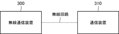
- FIG. 10 is a diagram illustrating a configuration example of a network for wireless communication according to the third embodiment of the present invention.
- the wireless communication device 300 is connected to another communication device 310 via a wireless line.
- the other communication device may not be one of the communication devices 310.
- a plurality of other communication devices may be provided in the wireless communication network of the present embodiment.
- the wireless communication device 300 performs point-to-point wireless communication with at least one of the other communication devices (that is, the communication device 310) after activation. When a predetermined signal is input, the wireless communication device 300 assigns a predetermined identification number to another communication device 310.
- the predetermined identification number is a predetermined IP address, and is set in the wireless communication apparatus 300 by the administrator of the wireless communication network of the present embodiment.
- the other communication device 310 may be a device that outputs the above-described predetermined signal when performing point-to-point wireless communication with the wireless communication device 300 after activation.
- the wireless communication device 300 After being activated, the wireless communication device 300 performs point-to-point wireless communication with at least one of the other communication devices (that is, the communication device 310).
- the other communication device 310 when the other communication device 310 performs point-to-point wireless communication with the wireless communication device 300, the other communication device 310 outputs a predetermined signal to the wireless communication device 300.
- the wireless communication device 300 assigns a predetermined identification number to the other communication device 310.
- the identification number may be an IP address.
- the wireless communication network can sufficiently suppress the introduction cost of the network. This is because, in the wireless communication network of the present embodiment, the wireless communication device itself has a DHCP server function, so that it is not necessary to provide a separate DHCP server.
- a wireless communication device that performs point-to-point wireless communication with at least one of the other communication devices, When a predetermined signal is input, a predetermined identification number is assigned to the other communication device.
- a wireless communication apparatus When the predetermined signal is input from the other communication device, the predetermined identification number is assigned to the other communication device.
- the wireless communication apparatus according to Supplementary Note 1, wherein: (Appendix 3) Communication means for receiving the predetermined signal from the other communication device; When the predetermined communication means receives the predetermined signal, the predetermined identification number is assigned to the other communication device via the predetermined communication means.
- the wireless communication apparatus according to any one of appendices 1 to 2, wherein the wireless communication apparatus is characterized in that (Appendix 4) Communication means for receiving the predetermined signal from the other communication device; When the communication unit receives the predetermined signal, a first network unit that is a network unit of a predetermined IP address corresponding to the communication unit that has received the predetermined signal, and a predetermined IP address corresponding to a default gateway Assigning the predetermined identification number to the other communication device via the communication means that has received the predetermined signal when the second network unit is different from the second network unit.
- the wireless communication apparatus according to any one of appendices 1 to 2, wherein the wireless communication apparatus is characterized in that (Appendix 5) A plurality of communication means; When the first network unit and the second network unit are the same, the communication unit other than the communication unit that has received the predetermined signal, and the network unit is the first network unit Outputting the predetermined signal from the communication means corresponding to the address;
- the wireless communication apparatus according to appendix 4, wherein: (Appendix 6)
- the wireless communication device according to any one of appendices 1 to 5, that is, the allocated wireless communication device, A wireless communication network characterized by the above.
- the wireless communication network according to any one of appendices 6 to 7, characterized in that: (Appendix 9) An identification number setting method for wireless communication means for performing point-to-point wireless communication with at least one of other communication means, When a predetermined signal is input, a predetermined identification number is assigned to the other communication means.
- the identification number setting method characterized by the above-mentioned.
- the wireless communication means is means having transmission / reception means for receiving the predetermined signal from the other communication means, When the predetermined transmission / reception means receives the predetermined signal, the predetermined identification number is assigned to the other communication means via the predetermined transmission / reception means.
- the identification number setting method is any one of appendices 9 to 10, characterized in that: (Appendix 12)
- the wireless communication means is means having transmission / reception means for receiving the predetermined signal from the other communication means, When the transmission / reception means receives the predetermined signal, a first network section that is a network section of a predetermined IP address corresponding to the transmission / reception means that has received the predetermined signal, and a predetermined IP address corresponding to a default gateway Assigning the predetermined identification number to the other communication means via the transmission / reception means that has received the predetermined signal when the second network part is a network part of
- the identification number setting method according to any one of appendices 9 to 10, characterized in that: (Appendix 13)
- the wireless communication means is a means having a plurality of the transmission / reception means, In the case where the first network unit and the second network unit are the same, the IP is the transmission / reception unit other than the transmission / reception unit that has received the predetermined signal, and the network unit is
- the identification number setting method according to appendix 12, characterized in that: (Appendix 14) The identification number is an IP address; The wireless communication device according to any one of appendices 1 to 5, wherein (Appendix 15) The identification number is an IP address; The wireless communication network according to any one of appendices 6 to 8, wherein the wireless communication network is characterized in that (Appendix 16) The identification number is an IP address; 14.
- a communication device including wireless communication means for performing point-to-point wireless communication, Receiving means for receiving a request signal for requesting IP address assignment from another communication device; An IP address assignment signal including an IP address to be assigned to the other communication device, a transmission means for transmitting to the other communication device;
- a communication apparatus comprising: (Appendix 18)
- the communication device includes a plurality of communication means including the wireless communication means, Among the communication means, when the wireless communication means receives the request signal, the wireless communication means transmits the IP address assignment signal, When the communication means other than the wireless communication means receives the request signal, the IP address assignment signal is not transmitted. Item 18.
- the communication device according to appendix 17, wherein (Appendix 19) Between the wireless line and the first type 1 wireless communication apparatus of the first network portion in which the first type 1 wireless communication apparatus, the wireless line, and the first type 2 wireless communication apparatus are connected in this order.
- a second network part in which a second type 2 wireless communication device is inserted The number of radio links in the second network part is the same as the number of radio lines in the first network part;
- the predetermined type identification number is assigned to the first type 1 wireless communication apparatus.
- a wireless communication network characterized by the above.
- (Appendix 20) Including at least one first type wireless communication apparatus including the first type first wireless communication apparatus; Each of the second type wireless communication devices assigns the predetermined identification number to the predetermined first type wireless communication device when the predetermined signal is input from the predetermined first type wireless communication device.
- Item 20 The wireless communication network according to appendix 19, wherein (Appendix 21) The second type wireless communication device includes a communication unit that receives the predetermined signal for each of the first type wireless communication devices to be connected.
- the second type wireless communication device When the communication unit receives the predetermined signal, the second type wireless communication device has a first network unit that is a network unit of a predetermined IP address corresponding to the communication unit that has received the predetermined signal; When the second network unit that is the network unit of the predetermined IP address corresponding to the default gateway is different, the first type wireless communication apparatus connected to the communication unit that has received the predetermined signal Assign an identification number,
- the wireless communication network according to any one of appendices 19 to 22, wherein (Appendix 24)
- the second type wireless communication device stores the predetermined identification number assigned to the first type wireless communication device as an assigned identification number, and among the predetermined identification numbers input from the monitoring device, the assignment type Holding the predetermined identification number excluding the completed identification number;
- the wireless communication network according to appendix 23 wherein
Landscapes
- Engineering & Computer Science (AREA)
- Computer Networks & Wireless Communication (AREA)
- Signal Processing (AREA)
- Databases & Information Systems (AREA)
- Mobile Radio Communication Systems (AREA)
- Small-Scale Networks (AREA)
Abstract
Description
本発明の第1の実施の形態における無線通信ネットワークは、図1に示されるように、隣接する無線通信装置とポイント・ツー・ポイントで無線通信を行う各無線通信装置10~13、20~21を備えるネットワークである。すなわち、本実施形態の無線通信ネットワークは、P2P通信ネットワークである。
まず、本発明の第1の実施の形態における無線通信ネットワークの構成と機能について説明する。
本実施形態の無線通信ネットワークは、図1に示されるように、無線通信装置10、11、12、13、20、21と、EMS(Element Management System)30を備える。
無線通信装置10、20は、隣接する無線通信装置11、21とポイント・ツー・ポイントで無線通信を行う機能を備える。
上述の機能を実現する為の無線通信装置10、20の構成について説明する。無線通信装置10、20の構成は、同じであるので、代表して無線通信装置20の構成について説明する。図2は、本発明の第1の実施の形態における無線通信ネットワークに備わる無線通信装置20の構成例を示す図である。
割当機能部103は、通信部101-1と、通信部101-2と、無線通信部102と、割当把握部104と、情報保持部105に接続される。情報保持部105は、通信部101-1と、通信部101-2と、割当把握部104に接続される。
無線通信装置10、20を構成する各部位の機能の詳細を以下に説明する。
無線通信装置11、12、13、21は、隣接する無線通信装置10、13、12、20とポイント・ツー・ポイントで無線通信を行う機能を備え、さらに、一般的なDHCPクライアント機能を備える。
EMS30は、一般的なEMSであり、各無線通信装置を監視する。EMS30には、本実施形態の無線通信ネットワークの管理者によってIPアドレスが設定される。EMS30は、設定されたIPアドレスを自身のIPアドレスとして保持する。以下、IPアドレス「172.18.3.1/24」が設定され、EMS30は、自身のIPアドレスとして保持したものとする。
図3、4は、本発明の第1の実施の形態における無線通信ネットワークに備わる無線通信装置の動作を説明する為の図である。図3、4を用いて、以下に本実施形態の無線通信装置の動作を説明する。
(1-1)IPアドレスの割り当てを行う無線通信装置の決定
まず、本実施形態の無線通信ネットワークを動作させるにあたり、本実施形態の無線通信ネットワークの管理者は、DHCPサーバの機能を備える無線通信装置10、20毎に、無線通信装置10、20とネットワークを形成する無線通信装置を決定する。
後述の「(2)本実施形態の無線通信ネットワークの動作」にて詳細を説明するが、無線通信装置10、20は、自分とネットワークを形成する無線通信装置(上述の「(1-1)」で決定した無線通信装置)にIPアドレスを割り当てる動作を行う。上述の動作を実現する為に、本実施形態の無線通信ネットワークの管理者は、DHCPサーバの機能を備える無線通信装置10、20に対し、以下の(1-2-1)~(1-2-3)に示す設定を事前に行う。
本実施形態の無線通信ネットワークの管理者は、無線通信装置10、20それぞれの割当機能部103に対し、無線通信装置10、20に備わる通信部101-iや無線通信部102(以下、「ポート」という)のIPアドレスを設定する。
次に、本実施形態の無線通信ネットワークの管理者は、無線通信装置10、20の情報保持部105に対し、各無線通信装置に割り当て可能なIPアドレスをそれぞれ設定する。
例えば、本実施形態の無線通信ネットワークの管理者は、無線通信装置10の情報保持部105に、「172.18.1.10/24」、「172.18.1.11/24」、…「172.18.1.49/24」の40個のIPアドレスを設定してもよい。いずれのIPアドレスもネットワーク1を表すネットワーク部(「172.18.1」)を有するIPアドレスである。
次に、本実施形態の無線通信ネットワークの管理者は、無線通信装置10、20の割当機能部103に対し、デフォルトゲートウェイのIPアドレスを設定する。
例えば、本実施形態の無線通信ネットワークの管理者は、無線通信装置20の割当機能部103に対し、デフォルトゲートウェイのIPアドレスとして、無線通信装置10の通信部101-1のIPアドレス「172.18.1.1/24」を設定してもよい。図3では、文字「X」と関連づけて、設定したIPアドレス「172.18.1.1/24」を記載している。
以下、本実施形態の無線通信ネットワークの動作について説明する。
まず、無線通信装置11~13、21は、ポイント・ツー・ポイント接続を確立した後、IPアドレスの割り当てを要求するパケット(以下、「割当要求パケット」という)を本実施形態の無線通信ネットワーク内にブロードキャストする。なぜなら、無線通信装置11~13、21は、DHCPサーバの機能を有する無線通信装置10、20のIPアドレスを知らないからである。図3の矢印は、無線通信装置11、21が割当要求パケットをブロードキャストしている様子を示している。
無線通信装置11~13、21からブロードキャストされた割当要求パケットは、無線通信装置10、20に入力される。
(動作概要)
無線通信装置10、20は、ブロードキャストされた割当要求パケットが入力されると、その割当要求パケットが担当する所定の無線通信装置からの割当要求パケットか否かを判別する。
上述の動作を実現する為に、無線通信装置10、20は、以下のS10~S21に示す処理を行う。以下のS10~S21は、無線通信装置20について説明しているが、無線通信装置10の場合でも同様である。但し、無線通信装置10は、「無線通信装置20」を「無線通信装置10」と、「ネットワーク2」を「ネットワーク1」と、「無線通信装置21」を「無線通信装置11~13」と読み替えて、以下のS10~S21を行う。
(S10)
まず、無線通信装置20の無線通信部102は、図4に示されるように、無線通信装置21から割当要求パケットが入力されると、その割当要求パケットを割当機能部103に出力する。
次に、無線通信装置20の割当機能部103は、割当要求パケットが入力されると、入力された割当要求パケットがネットワーク2を形成する無線通信装置21からの割当要求パケットか否かを判別する。
(I)
無線通信装置20の割当機能部103は、無線通信部102から割当要求パケットが入力されると、無線通信部102のIPアドレスのネットワーク部と、デフォルトゲートウェイのIPアドレスのネットワーク部と、が同じか否かを判別する。
デフォルトゲートウェイのIPアドレスのネットワーク部がネットワーク2以外のネットワークを表すものであるので、上述の(I)の判別は、割当要求パケットを入力した無線通信部102がネットワーク2以外のネットワークに属するのかどうかを判別している。
次に、無線通信装置20の割当機能部103は、上述の(I)の判別において、各ネットワーク部が同じと判別すると、入力された割当要求パケットはネットワーク2を形成する無線通信装置21からの割当要求パケットでないとみなす。
一方、無線通信装置20の割当機能部103は、各ネットワーク部が異なると判別すると、入力された割当要求パケットはネットワーク2を形成する無線通信装置21からの割当要求パケットとみなす。
上述の「(1)無線通信装置10、20(DHCPサーバ)への事前設定」において本実施形態の無線通信ネットワークの管理者は、無線通信装置20に対し、無線通信部102のIPアドレスを「172.18.2.1/24」と設定している。(図3のE参照。)また、本実施形態の無線通信ネットワークの管理者は、無線通信装置20にデフォルトゲートウェイのIPアドレスを「172.18.1.1/24」と設定している。(図3のX参照。)
無線通信装置20の割当機能部103は、上述の各IPアドレスのネットワーク部が異なっているので、上述の(III)の処理により、入力された割当要求パケットがネットワーク2を形成する無線通信装置21からの割当要求パケットと判別する。
(S12)
次に、割当機能部103は、図4に示されるように、入力された割当要求パケットがネットワーク2を形成する無線通信装置21からの割当要求パケットと判別した場合(S11でYesの場合)、割り当て可能なIPアドレスを情報保持部105に要求する。無線通信装置21にIPアドレスを割り当てる為である。
次に、無線通信装置20の情報保持部105は、割り当て可能なIPアドレスを要求されると、保持する割り当て可能なIPアドレスを全て割当機能部103に出力する。
次に、無線通信装置20の割当機能部103は、割り当て可能なIPアドレスが入力されると、その中からIPアドレスを1つ任意に選択する。
次に、無線通信装置20の割当機能部103は、選択したIPアドレスを一般的なパケットとする。このとき、無線通信装置20の割当機能部103は、入力された割当要求パケットからMACアドレスを抽出し、上述のパケットの宛先MACアドレスを、抽出したMACアドレスとする。
次に、無線通信装置20の割当機能部103は、S15で生成したパケットを、割当要求パケットを入力してきた無線通信部102、若しくは通信部101-iに出力する。ここでは、割当要求パケットを入力してきたのは、S10の通り、無線通信部102であるので、無線通信装置20の割当機能部103は、無線通信部102に対し、S15で生成したパケットを出力する。
次に、無線通信装置20の無線通信部102は、入力されたパケット(IPアドレス)を無線信号として無線通信装置21に出力する。
上述のS17の後、無線通信装置21は、無線通信装置20からパケットが入力される。
上述のS16の後、無線通信装置20は、無線通信装置21に割り当てたIPアドレスを他の装置に割り当てないように、以下のS18~S20に示す処理を行う。
上述のS16の後、無線通信装置20の割当機能部103は、上述のS14で選択したIPアドレスを割当把握部104に出力する。
次に、無線通信装置20の割当把握部104は、割当機能部103からIPアドレスが入力されると、IPアドレスを割り当てないよう要求する信号(以下、「割当不可信号」という)を情報保持部105に出力する。なお、無線通信装置20の割当把握部104は、上述の割当不可信号に、入力されたIPアドレスを含めて出力する。
次に、無線通信装置20の情報保持部105は、割当不可信号が入力されると、その信号からIPアドレスを抽出し、抽出したIPアドレスを、保持する割り当て可能なIPアドレスから削除する。また、無線通信装置20の情報保持部105は、抽出したIPアドレスを、割り当て済であるIPアドレスとして記憶する。
(S21)
次に、無線通信装置20の通信部101-i(例えば通信部101-1)は、図4に示されるように、無線通信装置(例えば無線通信装置11)から割当要求パケットが入力された場合には、その割当要求パケットを割当機能部103に出力する。
次に、無線通信装置20の割当機能部103は、割当要求パケットが入力されると、上述のS11と同様、入力された割当要求パケットがネットワーク2を形成する無線通信装置21からの割当要求パケットか否かを判別する。
具体的には、無線通信装置20の割当機能部103は、上述の(I)~(III)に示した手順を実施する。但し、無線通信装置20の割当機能部103は、「無線通信部102」を「通信部101-i」と読み替えて、上述の(I)~(III)に示した手順を実施する。
無線通信装置20の割当機能部103は、入力された割当要求パケットがネットワーク2を形成する無線通信装置21からの割当要求パケットでないと判別した場合(S11でNoの場合)、入力された割当要求パケットを他の無線通信装置13に転送する。
具体的には、無線通信装置20の割当機能部103は、入力された割当要求パケットを他の通信部に出力する。ここで、他の通信部とは、割当要求パケットが入力された通信部(ここでは通信部101-1)以外の通信部で、且つ、割当要求パケットが入力された通信部のIPアドレスのネットワーク部と同じネットワーク部を有するIPアドレスの通信部のことである。ここでは上述の他の通信部として、通信部101-2が該当する。通信部101-2は、入力された割当要求パケットを、接続されている有線回線を介して無線通信装置13に出力する。
上述の無線通信装置20から出力された割当要求パケットは無線通信装置13に届く。DHCPサーバの機能がない無線通信装置13は、入力された割当要求パケットを隣接する無線通信装置12に転送する。無線通信装置12は、転送する無線通信装置がないので、入力された割当要求パケットを破棄する。
なお、DHCPサーバの機能を有する無線通信装置20には、無線通信装置11、21以外に無線通信装置12、13からもブロードキャストされた割当要求パケットが入力される。その場合も無線通信装置20は、割当要求パケットが入力されたことを契機に上述のS10~S22の動作を行う。
無線通信装置20は、上述のように、各無線通信装置から割当要求パケットが入力され、上述のS10~S22を実施した結果、自分とネットワーク2を形成する無線通信装置21にIPアドレスを割り当てる。また、無線通信装置10も、各無線通信装置から割当要求パケットが入力され、上述のS10~S22を実施した結果、自分とネットワーク1を形成する無線通信装置11~13にIPアドレスを割り当てる。
図5は、本発明の第1の実施の形態における無線通信ネットワークのその他の構成例(各無線通信装置が無線回線で接続された場合)を示す図である。図6は、本発明の第1の実施の形態における無線通信システムに備わる無線通信装置20のその他の構成例を示す図である。
本実施形態によれば、無線通信ネットワークは、ネットワークの導入コストを十分に抑えられる。なぜなら、本実施形態の無線通信ネットワークでは、無線通信装置自体がDHCPサーバの機能を備えるので、別途DHCPサーバを設ける必要がないからである。
次に、本発明の第2の実施の形態について説明する。
図7は、本発明の第2の実施の形態における無線通信ネットワークの構成例を示す図である。図8は、本発明の第1の実施の形態における無線通信ネットワークに備わる無線通信装置の構成例を示す図である。
第2の実施の形態における無線通信ネットワークは、図7に示されるように、EMS30と無線通信装置10、20の代わりに、EMS230と無線通信装置210、220を備える。また、無線通信装置210、220は、図8に示されるように、通信部101-i(i=1~有線回線を介して接続される装置の数)の代わりに、通信部201-i(i=1~有線回線を介して接続される装置の数)を備える。さらに、無線通信装置210、220は、無線通信部102、割当機能部103、情報保持部105の代わりに、無線通信部202、割当機能部203、情報保持部205を備える。
EMS230は、本実施形態の無線通信ネットワークの管理者によって事前に各種IPアドレスが設定される。各種IPアドレスとは、無線通信装置210、220の各ポートのIPアドレス、無線通信装置210、220が無線通信装置11~13、21に割り当て可能なIPアドレス、及び無線通信装置210、220が使用するデフォルトゲートウェイのIPアドレスである。
無線通信装置210、220は、EMS230からパケットが入力されると、入力されたパケットから各種IPアドレスを取得し、保持する。また、無線通信装置210、220は、割り当て可能なIPアドレスを全て割り当てた場合、IPアドレス割り当て済を示すパケットをEMS230に出力する。このとき、無線通信装置210、220は、自身のIPアドレスを上述のIPアドレス割り当て済を示すパケットに含めて出力する。
無線通信装置210、220の通信部201-iは、EMS230からパケットが入力されると、そのパケットを割当機能部203に出力する。通信部201-iは、割当機能部203からIPアドレス割り当て済を示すパケットが入力されると、そのパケットをEMS230に出力する。
図9は、本発明の第2の実施の形態における無線通信ネットワークに備わる無線通信装置の動作を説明する為の図である。図9を用いて、本実施形態の無線通信装置の動作を説明する。
(S30)
まず、EMS230は、図9に示されるように、本実施形態の無線通信ネットワークの管理者により所定の操作が行われると、設定されている各種IPアドレスをパケットとして無線通信装置210の通信部201-1に出力する。
次に、無線通信装置210は、EMS230からパケットが入力されると、入力されたパケットから各種IPアドレス1を抽出し、自身に設定する。
(S32)
上述のS30の後、EMS230は、本実施形態の無線通信ネットワークの管理者により所定の操作が行われると、設定されている各種IPアドレスをパケットとして無線通信装置220に出力する。
次に、無線通信装置220は、各種IPアドレス2を含むパケットがEMS230から入力されると、入力されたパケットから上述の各種IPアドレス2を抽出し、自身に設定する。
無線通信装置210、220は、上述のS10~S22を繰り返し、割り当て可能なIPアドレスを全て各無線通信装置に割り当ててしまい、割り当て可能なIPアドレスを1つも保持しなくなった場合には、その旨をEMS230に通知する。具体的には、無線通信装置210、220は、以下のS40~S43の動作を行う。
まず、無線通信装置210、220の情報保持部205は、上述のS13において、保持する割り当て可能なIPアドレスが1つもないときには、IPアドレス割り当て済を示す信号を割当機能部203に出力する。
次に、無線通信装置210、220の割当機能部203は、上述のIPアドレス割り当て済を示す信号が入力されると、上述のS14を実施せず、IPアドレス割り当て済を示すパケットを通信部201-1に出力する。
次に、無線通信装置210、220の通信部201-1は、入力されたIPアドレス割り当て済を示すパケットをEMS230宛てに出力する。
次に、EMS230は、IPアドレス割り当て済を示すパケットが入力されると、そのパケットから無線通信装置に対応するIPアドレスを抽出し、そのIPアドレスを自身に備わる画面に表示する。このとき、EMS230は、IPアドレスの下に、「上記IPアドレスの無線通信装置(DHCPサーバ)は、割り当てられたIPアドレスを全て使い切りました。」と表示してもよい。
本実施形態の無線通信ネットワークの管理者は、EMS230の表示を確認すると、IPアドレスを全て割り当てた無線通信装置に対し、新たに割り当て可能なIPアドレスを設定する。上述の動作は、本実施形態の無線通信ネットワークの管理者が、所定の操作をEMS230に行い、さらに、本実施形態の無線通信ネットワークが以下のS44~S46を実施することで実現される。
まず、EMS230は、本実施形態の無線通信ネットワークの管理者により所定の操作が行われると、入力されたIPアドレス割り当て済を示すパケットから通信部201-1のIPアドレスを抽出する。
次に、EMS230は、抽出したIPアドレスに対応する通信部201-1に対し、各種IPアドレス1、2よりも割り当て可能なIPアドレスが多い各種IPアドレス(以下、「各種IPアドレス3」という)をパケットとして出力する。
次に、無線通信装置210の通信部201-1は、EMS230からパケットが入力されると、上述のS31に示した(a)の動作を行い、その後、無線通信装置210の各機能部は、上述のS31に示した(b)~(e)の動作を行う。但し、無線通信装置210の各機能部は、「各種IPアドレス1」を「各種IPアドレス3」と読み替えて、上述のS31に示した(b)~(e)の動作を行うものとする。なお、無線通信装置210の情報保持部205は、上述(e)の代わりに以下の(e´)を実施し、すでに割り当て済のIPアドレスを保持しないようにする。
情報保持部205は、割当機能部203から割り当て可能なIPアドレスが入力されると、上述のS18で記憶した割り当て済であるIPアドレスを読み出す。情報保持部205は、入力された割り当て可能なIPアドレスの中から(読み出した)割り当て済であるIPアドレスを除くIPアドレスを抽出し、抽出したIPアドレスを、新たな割り当て可能なIPアドレスとして記憶する。
本実施形態によれば、無線通信ネットワークは、DHCP機能を備える無線通信装置に対し、各種IPアドレスをEMS230から設定することができる。
次に、本発明の第3の実施の形態について説明する。
図10は、本発明の第3の実施の形態における無線通信のネットワークの構成例を示す図である。
まず、無線通信装置300は、起動後、他の通信装置の少なくとも1つ(すなわち、通信装置310)とポイント・ツー・ポイント無線通信を行う。
本実施形態によれば、無線通信ネットワークは、ネットワークの導入コストを十分に抑えられる。なぜなら、本実施形態の無線通信ネットワークでは、無線通信装置自体がDHCPサーバの機能を備えるので、別途DHCPサーバを設ける必要がないからである。
(付記1)
他の通信装置の少なくとも1つとポイント・ツー・ポイント無線通信を行う無線通信装置であって、
所定の信号が入力されると、前記他の通信装置に所定の識別番号を割り当てる、
ことを特徴とする無線通信装置。
(付記2)
前記他の通信装置から前記所定の信号が入力されると、前記他の通信装置に前記所定の識別番号を割り当てる、
ことを特徴とする付記1に記載の無線通信装置。
(付記3)
前記他の通信装置から前記所定の信号を受信する通信手段を備え、
所定の前記通信手段が前記所定の信号を受信すると、前記所定の通信手段を介して前記他の通信装置に前記所定の識別番号を割り当てる、
ことを特徴とする付記1乃至2のいずれか1項に記載の無線通信装置。
(付記4)
前記他の通信装置から前記所定の信号を受信する通信手段を備え、
前記通信手段が前記所定の信号を受信すると、前記所定の信号を受信した前記通信手段に対応する所定のIPアドレスのネットワーク部である第1のネットワーク部と、デフォルトゲートウェイに対応する所定のIPアドレスのネットワーク部である第2のネットワーク部とが異なる場合に、前記所定の信号を受信した前記通信手段を介して前記他の通信装置に前記所定の識別番号を割り当てる、
ことを特徴とする付記1乃至2のいずれか1項に記載の無線通信装置。
(付記5)
前記通信手段を複数備え、
前記第1のネットワーク部と前記第2のネットワーク部が同じ場合には、前記所定の信号を受信した前記通信手段以外の前記通信手段で、且つ、ネットワーク部が前記第1のネットワーク部であるIPアドレスに対応する前記通信手段より前記所定の信号を出力する、
ことを特徴とする付記4に記載の無線通信装置。
(付記6)
付記1乃至5のいずれか1項に記載の無線通信装置、すなわち割当無線通信装置を備える、
ことを特徴とする無線通信ネットワーク。
(付記7)
監視装置を備え、
前記監視装置は、保持する前記所定の識別番号を前記割当無線通信装置に出力し、
前記割当無線通信装置は、入力された前記所定の識別番号を保持する、
ことを特徴とする付記6に記載の無線通信ネットワーク。
(付記8)
第1の前記他の通信装置、無線回線及び第1の前記割当無線通信装置がこの順に接続された第1の第1のネットワーク部分の前記無線回線と前記第1の他の通信装置との間に第2の前記割当無線通信装置が挿入された第2のネットワーク部分を備え、
前記第2のネットワーク部分の無線回線の数は、前記第1のネットワーク部分の無線回線の数と同じであり、
少なくとも前記第2の割当無線通信装置が、前記所定の信号が入力されると、前記所定の識別番号を前記第1の他の通信装置に割り当てる、
ことを特徴とする付記6乃至7のいずれか1項に記載の無線通信ネットワーク。
(付記9)
他の通信手段の少なくとも1つとポイント・ツー・ポイント無線通信を行う無線通信手段の識別番号設定方法であって、
所定の信号が入力されると、前記他の通信手段に所定の識別番号を割り当てる、
ことを特徴とする識別番号設定方法。
(付記10)
前記他の通信手段から前記所定の信号が入力されると、前記他の通信手段に前記所定の識別番号を割り当てる、
ことを特徴とする付記9に記載の識別番号設定方法。
(付記11)
前記無線通信手段は、前記他の通信手段から前記所定の信号を受信する送受信手段を有する手段であって、
所定の前記送受信手段が前記所定の信号を受信すると、前記所定の送受信手段を介して前記他の通信手段に前記所定の識別番号を割り当てる、
ことを特徴とする付記9乃至10のいずれか1項に記載の識別番号設定方法。
(付記12)
前記無線通信手段は、前記他の通信手段から前記所定の信号を受信する送受信手段を有する手段であって、
前記送受信手段が前記所定の信号を受信すると、前記所定の信号を受信した前記送受信手段に対応する所定のIPアドレスのネットワーク部である第1のネットワーク部と、デフォルトゲートウェイに対応する所定のIPアドレスのネットワーク部である第2のネットワーク部とが異なる場合に、前記所定の信号を受信した前記送受信手段を介して前記他の通信手段に前記所定の識別番号を割り当てる、
ことを特徴とする付記9乃至10のいずれか1項に記載の識別番号設定方法。
(付記13)
前記無線通信手段は、前記送受信手段を複数有する手段であって、
前記第1のネットワーク部と前記第2のネットワーク部が同じ場合には、前記所定の信号を受信した前記送受信手段以外の前記送受信手段で、且つ、ネットワーク部が前記第1のネットワーク部であるIPアドレスに対応する前記送受信手段より前記所定の信号を出力する、
ことを特徴とする付記12に記載の識別番号設定方法。
(付記14)
前記識別番号は、IPアドレスである、
ことを特徴とする付記1乃至5のいずれか1項に記載の無線通信装置。
(付記15)
前記識別番号は、IPアドレスである、
ことを特徴とする付記6乃至8のいずれか1項に記載の無線通信ネットワーク。
(付記16)
前記識別番号は、IPアドレスである、
ことを特徴とする付記9乃至13のいずれか1項に記載の識別番号設定方法。
(付記17)
ポイント・ツー・ポイントで無線通信を行う無線通信手段を備えた通信装置であって、
他の通信装置からIPアドレス割り当てを要求する要求信号を受信する受信手段と、
前記他の通信装置に割り当てるIPアドレスを含むIPアドレス割り当て信号を、前記他の通信装置に送信する送信手段と、
を備えることを特徴とする通信装置。
(付記18)
前記通信装置は、前記無線通信手段を含む複数の通信手段を備え、
前記通信手段のうち、前記無線通信手段が前記要求信号を受信した場合は前記無線通信手段から前記IPアドレス割当て信号を送信し、
前記無線通信手段以外の前記通信手段が前記要求信号を受信した場合は前記IPアドレス割当て信号を送信しない、
ことを特徴とする付記17に記載の通信装置。
(付記19)
第1の第1種無線通信装置、無線回線及び第1の第2種無線通信装置がこの順に接続された第1のネットワーク部分の前記無線回線と前記第1の第1種無線通信装置の間に第2の第2種無線通信装置が挿入された第2のネットワーク部分を備え、
前記第2のネットワーク部分の無線回線の数は、前記第1のネットワーク部分の無線回線の数と同じであり、
少なくとも前記第2の第2種無線通信装置が、所定の信号が入力されると、所定の識別番号を前記第1の第1種無線通信装置に割り当てる、
ことを特徴とする無線通信ネットワーク。
(付記20)
前記第1の第1種無線通信装置を含む少なくとも1つの前記第1種無線通信装置を備え、
前記第2種無線通信装置各々は、所定の前記第1種無線通信装置から前記所定の信号が入力されると、前記所定の識別番号を所定の前記第1種無線通信装置に割り当てる、
ことを特徴とする付記19に記載の無線通信ネットワーク。
(付記21)
前記第2種無線通信装置は、接続される前記第1種無線通信装置毎に、前記所定の信号を受信する通信手段を備え、
前記第2種無線通信装置は、前記通信手段が前記所定の信号を受信すると、前記所定の信号を受信した前記通信手段に対応する所定のIPアドレスのネットワーク部である第1のネットワーク部と、デフォルトゲートウェイに対応する所定のIPアドレスのネットワーク部である第2のネットワーク部とが異なる場合に、前記所定の信号を受信した前記通信手段と接続される前記第1種無線通信装置に前記所定の識別番号を割り当てる、
ことを特徴とする付記20に記載の無線通信ネットワーク。
(付記22)
前記第2種無線通信装置は、前記第1のネットワーク部と前記第2のネットワーク部が同じ場合には、前記所定の信号を受信した前記通信手段以外の前記通信手段で、且つ、ネットワーク部が前記第1のネットワーク部であるIPアドレスに対応する前記通信手段より前記所定の信号を出力する、
ことを特徴とする付記21に記載の無線通信ネットワーク。
(付記23)
監視装置を備え、
前記監視装置は、保持する前記所定の識別番号を前記第2種無線通信装置に出力し、
前記第2種無線通信装置は、入力された前記所定の識別番号を保持する、
ことを特徴とする付記19乃至22のいずれか1項に記載の無線通信ネットワーク。
(付記24)
前記第2種無線通信装置は、前記第1種無線通信装置に割り当てた前記所定の識別番号を割当済識別番号として記憶し、前記監視装置から入力された前記所定の識別番号のうち、前記割当済識別番号を除いた前記所定の識別番号を保持する、
ことを特徴とする付記23に記載の無線通信ネットワーク。
10、11、12、13、20、21、210、220、300、513 無線通信装置
30、230 EMS
40、41、520、521 無線回線
101-i、201-i 通信部
102、202 無線通信部
103、203 割当機能部
104 割当把握部
105、205 情報保持部
310 通信装置
501 ルータ
502 無線LANアクセスポイント端末
503-1、503-2、503-3 無線LAN端末
504 DHCPサーバ
505-1、505-2、505-3 DHCPクライアント機能部
506 無線LAN
Claims (18)
- 他の通信装置の少なくとも1つとポイント・ツー・ポイント無線通信を行う無線通信装置であって、
所定の信号が入力されると、前記他の通信装置に所定の識別番号を割り当てる、
ことを特徴とする無線通信装置。 - 前記他の通信装置から前記所定の信号が入力されると、前記他の通信装置に前記所定の識別番号を割り当てる、
ことを特徴とする請求項1に記載の無線通信装置。 - 前記他の通信装置から前記所定の信号を受信する通信手段を備え、
所定の前記通信手段が前記所定の信号を受信すると、前記所定の通信手段を介して前記他の通信装置に前記所定の識別番号を割り当てる、
ことを特徴とする請求項1乃至2のいずれか1項に記載の無線通信装置。 - 前記他の通信装置から前記所定の信号を受信する通信手段を備え、
前記通信手段が前記所定の信号を受信すると、前記所定の信号を受信した前記通信手段に対応する所定のIPアドレスのネットワーク部である第1のネットワーク部と、デフォルトゲートウェイに対応する所定のIPアドレスのネットワーク部である第2のネットワーク部とが異なる場合に、前記所定の信号を受信した前記通信手段を介して前記他の通信装置に前記所定の識別番号を割り当てる、
ことを特徴とする請求項1乃至2のいずれか1項に記載の無線通信装置。 - 前記通信手段を複数備え、
前記第1のネットワーク部と前記第2のネットワーク部が同じ場合には、前記所定の信号を受信した前記通信手段以外の前記通信手段で、且つ、ネットワーク部が前記第1のネットワーク部であるIPアドレスに対応する前記通信手段より前記所定の信号を出力する、
ことを特徴とする請求項4に記載の無線通信装置。 - 請求項1乃至5のいずれか1項に記載の無線通信装置、すなわち割当無線通信装置を備える、
ことを特徴とする無線通信ネットワーク。 - 監視装置を備え、
前記監視装置は、保持する前記所定の識別番号を前記割当無線通信装置に出力し、
前記割当無線通信装置は、入力された前記所定の識別番号を保持する、
ことを特徴とする請求項6に記載の無線通信ネットワーク。 - 第1の前記他の通信装置、無線回線及び第1の前記割当無線通信装置がこの順に接続された第1の第1のネットワーク部分の前記無線回線と前記第1の他の通信装置との間に第2の前記割当無線通信装置が挿入された第2のネットワーク部分を備え、
前記第2のネットワーク部分の無線回線の数は、前記第1のネットワーク部分の無線回線の数と同じであり、
少なくとも前記第2の割当無線通信装置が、前記所定の信号が入力されると、前記所定の識別番号を前記第1の他の通信装置に割り当てる、
ことを特徴とする請求項6乃至7のいずれか1項に記載の無線通信ネットワーク。 - 他の通信手段の少なくとも1つとポイント・ツー・ポイント無線通信を行う無線通信手段の識別番号設定方法であって、
所定の信号が入力されると、前記他の通信手段に所定の識別番号を割り当てる、
ことを特徴とする識別番号設定方法。 - 前記他の通信手段から前記所定の信号が入力されると、前記他の通信手段に前記所定の識別番号を割り当てる、
ことを特徴とする請求項9に記載の識別番号設定方法。 - 前記無線通信手段は、前記他の通信手段から前記所定の信号を受信する送受信手段を有する手段であって、
所定の前記送受信手段が前記所定の信号を受信すると、前記所定の送受信手段を介して前記他の通信手段に前記所定の識別番号を割り当てる、
ことを特徴とする請求項9乃至10のいずれか1項に記載の識別番号設定方法。 - 前記無線通信手段は、前記他の通信手段から前記所定の信号を受信する送受信手段を有する手段であって、
前記送受信手段が前記所定の信号を受信すると、前記所定の信号を受信した前記送受信手段に対応する所定のIPアドレスのネットワーク部である第1のネットワーク部と、デフォルトゲートウェイに対応する所定のIPアドレスのネットワーク部である第2のネットワーク部とが異なる場合に、前記所定の信号を受信した前記送受信手段を介して前記他の通信手段に前記所定の識別番号を割り当てる、
ことを特徴とする請求項9乃至10のいずれか1項に記載の識別番号設定方法。 - 前記無線通信手段は、前記送受信手段を複数有する手段であって、
前記第1のネットワーク部と前記第2のネットワーク部が同じ場合には、前記所定の信号を受信した前記送受信手段以外の前記送受信手段で、且つ、ネットワーク部が前記第1のネットワーク部であるIPアドレスに対応する前記送受信手段より前記所定の信号を出力する、
ことを特徴とする請求項12に記載の識別番号設定方法。 - 前記識別番号は、IPアドレスである、
ことを特徴とする請求項1乃至5のいずれか1項に記載の無線通信装置。 - 前記識別番号は、IPアドレスである、
ことを特徴とする請求項6乃至8のいずれか1項に記載の無線通信ネットワーク。 - 前記識別番号は、IPアドレスである、
ことを特徴とする請求項9乃至13のいずれか1項に記載の識別番号設定方法。 - ポイント・ツー・ポイントで無線通信を行う無線通信手段を備えた通信装置であって、
他の通信装置からIPアドレス割り当てを要求する要求信号を受信する受信手段と、
前記他の通信装置に割り当てるIPアドレスを含むIPアドレス割り当て信号を、前記他の通信装置に送信する送信手段と、
を備えることを特徴とする通信装置。 - 前記通信装置は、前記無線通信手段を含む複数の通信手段を備え、
前記通信手段のうち、前記無線通信手段が前記要求信号を受信した場合は前記無線通信手段から前記IPアドレス割当て信号を送信し、
前記無線通信手段以外の前記通信手段が前記要求信号を受信した場合は前記IPアドレス割当て信号を送信しない、
ことを特徴とする請求項17に記載の通信装置。
Priority Applications (3)
| Application Number | Priority Date | Filing Date | Title |
|---|---|---|---|
| US15/107,995 US20160330614A1 (en) | 2013-12-27 | 2014-12-12 | Wireless communication device, wireless communication network, and identification-number setting method |
| EP14873230.8A EP3089492A4 (en) | 2013-12-27 | 2014-12-12 | Wireless communication device, wireless communication network, and identification-number setting method |
| CN201480071327.6A CN105850166A (zh) | 2013-12-27 | 2014-12-12 | 无线通信设备/无线通信网络以及标识号设定方法 |
Applications Claiming Priority (2)
| Application Number | Priority Date | Filing Date | Title |
|---|---|---|---|
| JP2013270781 | 2013-12-27 | ||
| JP2013-270781 | 2013-12-27 |
Publications (1)
| Publication Number | Publication Date |
|---|---|
| WO2015098029A1 true WO2015098029A1 (ja) | 2015-07-02 |
Family
ID=53477935
Family Applications (1)
| Application Number | Title | Priority Date | Filing Date |
|---|---|---|---|
| PCT/JP2014/006214 Ceased WO2015098029A1 (ja) | 2013-12-27 | 2014-12-12 | 無線通信装置、無線通信ネットワーク、識別番号設定方法 |
Country Status (4)
| Country | Link |
|---|---|
| US (1) | US20160330614A1 (ja) |
| EP (1) | EP3089492A4 (ja) |
| CN (1) | CN105850166A (ja) |
| WO (1) | WO2015098029A1 (ja) |
Families Citing this family (3)
| Publication number | Priority date | Publication date | Assignee | Title |
|---|---|---|---|---|
| WO2017091744A1 (en) * | 2015-11-25 | 2017-06-01 | Lantronix, Inc. | Bridging with web manager access |
| CN110870289B (zh) * | 2017-07-07 | 2021-06-01 | 华为技术有限公司 | 一种局域网设备恢复上网的方法和装置 |
| CN110545334A (zh) * | 2018-05-29 | 2019-12-06 | 硕天科技股份有限公司 | Ip地址显示设备及采用此ip地址显示设备的电源分配器与不断电系统 |
Citations (7)
| Publication number | Priority date | Publication date | Assignee | Title |
|---|---|---|---|---|
| JP2004248180A (ja) * | 2003-02-17 | 2004-09-02 | Kddi Corp | 異なる無線通信メディアの切替方法及びその通信状態測定方法 |
| JP2006191570A (ja) * | 2004-12-30 | 2006-07-20 | Lg Electronics Inc | 移動通信網に接続できない無線端末機へのip割り当て方法及び該方法を実現できる移動通信端末機 |
| JP2006279168A (ja) * | 2005-03-28 | 2006-10-12 | Kddi Corp | アドホック網を構成する通信装置、ブリッジ装置及び通信システム |
| JP2008078990A (ja) | 2006-09-21 | 2008-04-03 | Nec Access Technica Ltd | ネットワークシステム、アクセスポイント端末、アドレス決定方法、及びプログラム |
| WO2010032382A1 (ja) * | 2008-09-19 | 2010-03-25 | 三洋電機株式会社 | 通信方法およびそれを利用した端末装置 |
| JP2012195737A (ja) * | 2011-03-16 | 2012-10-11 | Shikoku Electric Power Co Inc | 無線通信システム |
| JP2012249213A (ja) | 2011-05-31 | 2012-12-13 | Buffalo Inc | Ipアドレス割り当てシステム及びipアドレス割り当て方法 |
Family Cites Families (11)
| Publication number | Priority date | Publication date | Assignee | Title |
|---|---|---|---|---|
| US7457293B2 (en) * | 2004-04-05 | 2008-11-25 | Panasonic Corporation | Communication apparatus, method and program for realizing P2P communication |
| KR101085629B1 (ko) * | 2009-03-16 | 2011-11-22 | 삼성전자주식회사 | 이동통신 단말에서 ⅰp 통신의 네트워크 설정 방법 및 장치 |
| KR20120052092A (ko) * | 2010-11-15 | 2012-05-23 | 삼성전자주식회사 | 네트워크 중계 방법, 네트워크 접속 방법 및 이를 적용한 무선 통신 그룹 |
| CN103166990B (zh) * | 2011-12-13 | 2016-04-27 | 中国电信股份有限公司 | P2p对等连接建立方法及系统 |
| KR101849925B1 (ko) * | 2012-02-24 | 2018-04-18 | 삼성전자주식회사 | 무선 통신 네트워크에서 디바이스 탐색 방법 및 장치 |
| KR102005771B1 (ko) * | 2012-02-24 | 2019-10-01 | 삼성전자주식회사 | 무선 통신 네트워크에서 ip 주소 할당 방법 및 장치 |
| JPWO2013145045A1 (ja) * | 2012-03-30 | 2015-08-03 | Necカシオモバイルコミュニケーションズ株式会社 | 無線デバイス、アドレス決定方法、通信システム及び無線端末 |
| CN102833363A (zh) * | 2012-08-20 | 2012-12-19 | 大唐移动通信设备有限公司 | 一种ip地址分配方法、装置及系统 |
| US20140064147A1 (en) * | 2012-08-29 | 2014-03-06 | Qualcomm Incorporated | Methods and apparatus for wan enabled peer discovery |
| KR101975992B1 (ko) * | 2012-09-26 | 2019-05-08 | 에이치피프린팅코리아 유한회사 | WiFi Direct를 지원하는 화상형성장치 및 그것의 인터넷 접속 제어 방법 |
| US9900931B2 (en) * | 2013-05-02 | 2018-02-20 | Qualcomm Incorporated | Method and apparatus for device to device relay selection |
-
2014
- 2014-12-12 US US15/107,995 patent/US20160330614A1/en not_active Abandoned
- 2014-12-12 WO PCT/JP2014/006214 patent/WO2015098029A1/ja not_active Ceased
- 2014-12-12 CN CN201480071327.6A patent/CN105850166A/zh active Pending
- 2014-12-12 EP EP14873230.8A patent/EP3089492A4/en not_active Withdrawn
Patent Citations (7)
| Publication number | Priority date | Publication date | Assignee | Title |
|---|---|---|---|---|
| JP2004248180A (ja) * | 2003-02-17 | 2004-09-02 | Kddi Corp | 異なる無線通信メディアの切替方法及びその通信状態測定方法 |
| JP2006191570A (ja) * | 2004-12-30 | 2006-07-20 | Lg Electronics Inc | 移動通信網に接続できない無線端末機へのip割り当て方法及び該方法を実現できる移動通信端末機 |
| JP2006279168A (ja) * | 2005-03-28 | 2006-10-12 | Kddi Corp | アドホック網を構成する通信装置、ブリッジ装置及び通信システム |
| JP2008078990A (ja) | 2006-09-21 | 2008-04-03 | Nec Access Technica Ltd | ネットワークシステム、アクセスポイント端末、アドレス決定方法、及びプログラム |
| WO2010032382A1 (ja) * | 2008-09-19 | 2010-03-25 | 三洋電機株式会社 | 通信方法およびそれを利用した端末装置 |
| JP2012195737A (ja) * | 2011-03-16 | 2012-10-11 | Shikoku Electric Power Co Inc | 無線通信システム |
| JP2012249213A (ja) | 2011-05-31 | 2012-12-13 | Buffalo Inc | Ipアドレス割り当てシステム及びipアドレス割り当て方法 |
Non-Patent Citations (1)
| Title |
|---|
| See also references of EP3089492A4 |
Also Published As
| Publication number | Publication date |
|---|---|
| EP3089492A4 (en) | 2017-06-14 |
| CN105850166A (zh) | 2016-08-10 |
| US20160330614A1 (en) | 2016-11-10 |
| EP3089492A1 (en) | 2016-11-02 |
Similar Documents
| Publication | Publication Date | Title |
|---|---|---|
| US9438555B2 (en) | Communicating with a distribution system via an uplink access point | |
| US20130182651A1 (en) | Virtual Private Network Client Internet Protocol Conflict Detection | |
| EP2166799A1 (en) | Method and apparatus for implementing a virtual network | |
| CN102202104A (zh) | 管理网络设备内的分布式地址池 | |
| CN102647486A (zh) | 地址分配方法、设备和系统 | |
| CN104584640A (zh) | 具有中继的网络中仅能有3个地址的接入点中的层2地址管理 | |
| KR101694223B1 (ko) | 패킷을 전송하는 방법, 라우팅 브리지, 및 시스템 | |
| US20170005930A1 (en) | Communication device and communication method | |
| CN104185192A (zh) | 一种管理设备的访问方法及相关设备 | |
| CN112654049A (zh) | 用于配置无线通信覆盖扩展系统的方法及实现所述方法的无线通信覆盖扩展系统 | |
| CN107809386B (zh) | Ip地址转换方法、路由设备和通信系统 | |
| CN103152444B (zh) | 中继方式的网络地址转换及报文传输方法及装置、系统 | |
| US20160330614A1 (en) | Wireless communication device, wireless communication network, and identification-number setting method | |
| CN103780494A (zh) | 一种用户信息获取方法和装置 | |
| CN113497752B (zh) | 一种报文发送方法、第一网络设备及网络系统 | |
| CN110266715B (zh) | 异地访问方法、装置、设备与计算机可读存储介质 | |
| JP6424740B2 (ja) | パケット中継装置およびパケット中継方法 | |
| KR101296376B1 (ko) | IPv6 네트워크에서 호스트 장치 차단 방법, 그리고 이를 구현한 네트워크 관리장치 | |
| CN104518937B (zh) | 虚拟局域网vlan多设备间通信的方法及装置 | |
| US20170265067A1 (en) | Communication terminal device and transmission and reception method therefor, and recording medium containing computer program | |
| JP5746109B2 (ja) | 通信装置、通信システム及び無線アクセスポイント接続方法 | |
| WO2011139138A1 (en) | Method of providing multi address binding in a network | |
| JP2019009637A (ja) | ネットワーク監視装置 | |
| US20130089017A1 (en) | Communication system and method | |
| KR102324113B1 (ko) | 적어도 하나 이상의 중계기와 적어도 하나 이상의 네트워크 단말기 간의 통신방법 |
Legal Events
| Date | Code | Title | Description |
|---|---|---|---|
| 121 | Ep: the epo has been informed by wipo that ep was designated in this application |
Ref document number: 14873230 Country of ref document: EP Kind code of ref document: A1 |
|
| WWE | Wipo information: entry into national phase |
Ref document number: 15107995 Country of ref document: US |
|
| NENP | Non-entry into the national phase |
Ref country code: DE |
|
| REEP | Request for entry into the european phase |
Ref document number: 2014873230 Country of ref document: EP |
|
| WWE | Wipo information: entry into national phase |
Ref document number: 2014873230 Country of ref document: EP |
|
| NENP | Non-entry into the national phase |
Ref country code: JP |