WO2015098656A1 - エアレスタイヤ - Google Patents
エアレスタイヤ Download PDFInfo
- Publication number
- WO2015098656A1 WO2015098656A1 PCT/JP2014/083428 JP2014083428W WO2015098656A1 WO 2015098656 A1 WO2015098656 A1 WO 2015098656A1 JP 2014083428 W JP2014083428 W JP 2014083428W WO 2015098656 A1 WO2015098656 A1 WO 2015098656A1
- Authority
- WO
- WIPO (PCT)
- Prior art keywords
- spoke
- tire
- tire axial
- spoke plate
- plate portion
- Prior art date
- Legal status (The legal status is an assumption and is not a legal conclusion. Google has not performed a legal analysis and makes no representation as to the accuracy of the status listed.)
- Ceased
Links
Images


Classifications
-
- B—PERFORMING OPERATIONS; TRANSPORTING
- B60—VEHICLES IN GENERAL
- B60C—VEHICLE TYRES; TYRE INFLATION; TYRE CHANGING; CONNECTING VALVES TO INFLATABLE ELASTIC BODIES IN GENERAL; DEVICES OR ARRANGEMENTS RELATED TO TYRES
- B60C7/00—Non-inflatable or solid tyres
- B60C7/10—Non-inflatable or solid tyres characterised by means for increasing resiliency
- B60C7/14—Non-inflatable or solid tyres characterised by means for increasing resiliency using springs
-
- B—PERFORMING OPERATIONS; TRANSPORTING
- B60—VEHICLES IN GENERAL
- B60B—VEHICLE WHEELS; CASTORS; AXLES FOR WHEELS OR CASTORS; INCREASING WHEEL ADHESION
- B60B19/00—Wheels not otherwise provided for or having characteristics specified in one of the subgroups of this group
- B60B19/10—Wheels not otherwise provided for or having characteristics specified in one of the subgroups of this group with cooling fins
-
- B—PERFORMING OPERATIONS; TRANSPORTING
- B60—VEHICLES IN GENERAL
- B60B—VEHICLE WHEELS; CASTORS; AXLES FOR WHEELS OR CASTORS; INCREASING WHEEL ADHESION
- B60B27/00—Hubs
- B60B27/06—Hubs adapted to be fixed on axle
-
- B—PERFORMING OPERATIONS; TRANSPORTING
- B60—VEHICLES IN GENERAL
- B60B—VEHICLE WHEELS; CASTORS; AXLES FOR WHEELS OR CASTORS; INCREASING WHEEL ADHESION
- B60B5/00—Wheels, spokes, disc bodies, rims, hubs, wholly or predominantly made of non-metallic material
- B60B5/02—Wheels, spokes, disc bodies, rims, hubs, wholly or predominantly made of non-metallic material made of synthetic material
-
- B—PERFORMING OPERATIONS; TRANSPORTING
- B60—VEHICLES IN GENERAL
- B60B—VEHICLE WHEELS; CASTORS; AXLES FOR WHEELS OR CASTORS; INCREASING WHEEL ADHESION
- B60B9/00—Wheels of high resiliency, e.g. with conical interacting pressure-surfaces
- B60B9/26—Wheels of high resiliency, e.g. with conical interacting pressure-surfaces comprising resilient spokes
-
- B—PERFORMING OPERATIONS; TRANSPORTING
- B60—VEHICLES IN GENERAL
- B60C—VEHICLE TYRES; TYRE INFLATION; TYRE CHANGING; CONNECTING VALVES TO INFLATABLE ELASTIC BODIES IN GENERAL; DEVICES OR ARRANGEMENTS RELATED TO TYRES
- B60C7/00—Non-inflatable or solid tyres
- B60C7/10—Non-inflatable or solid tyres characterised by means for increasing resiliency
- B60C7/14—Non-inflatable or solid tyres characterised by means for increasing resiliency using springs
- B60C7/16—Non-inflatable or solid tyres characterised by means for increasing resiliency using springs of helical or flat coil form
- B60C7/18—Non-inflatable or solid tyres characterised by means for increasing resiliency using springs of helical or flat coil form disposed radially relative to wheel axis
-
- B—PERFORMING OPERATIONS; TRANSPORTING
- B60—VEHICLES IN GENERAL
- B60C—VEHICLE TYRES; TYRE INFLATION; TYRE CHANGING; CONNECTING VALVES TO INFLATABLE ELASTIC BODIES IN GENERAL; DEVICES OR ARRANGEMENTS RELATED TO TYRES
- B60C7/00—Non-inflatable or solid tyres
- B60C7/22—Non-inflatable or solid tyres having inlays other than for increasing resiliency, e.g. for armouring
-
- B—PERFORMING OPERATIONS; TRANSPORTING
- B60—VEHICLES IN GENERAL
- B60B—VEHICLE WHEELS; CASTORS; AXLES FOR WHEELS OR CASTORS; INCREASING WHEEL ADHESION
- B60B2310/00—Manufacturing methods
- B60B2310/20—Shaping
- B60B2310/202—Shaping by casting
-
- B—PERFORMING OPERATIONS; TRANSPORTING
- B60—VEHICLES IN GENERAL
- B60B—VEHICLE WHEELS; CASTORS; AXLES FOR WHEELS OR CASTORS; INCREASING WHEEL ADHESION
- B60B2310/00—Manufacturing methods
- B60B2310/20—Shaping
- B60B2310/204—Shaping by moulding, e.g. injection moulding, i.e. casting of plastics material
-
- B—PERFORMING OPERATIONS; TRANSPORTING
- B60—VEHICLES IN GENERAL
- B60B—VEHICLE WHEELS; CASTORS; AXLES FOR WHEELS OR CASTORS; INCREASING WHEEL ADHESION
- B60B2360/00—Materials; Physical forms thereof
- B60B2360/10—Metallic materials
-
- B—PERFORMING OPERATIONS; TRANSPORTING
- B60—VEHICLES IN GENERAL
- B60B—VEHICLE WHEELS; CASTORS; AXLES FOR WHEELS OR CASTORS; INCREASING WHEEL ADHESION
- B60B2360/00—Materials; Physical forms thereof
- B60B2360/30—Synthetic materials
- B60B2360/32—Plastic compositions
-
- B—PERFORMING OPERATIONS; TRANSPORTING
- B60—VEHICLES IN GENERAL
- B60B—VEHICLE WHEELS; CASTORS; AXLES FOR WHEELS OR CASTORS; INCREASING WHEEL ADHESION
- B60B2900/00—Purpose of invention
- B60B2900/10—Reduction of
- B60B2900/131—Vibrations
-
- B—PERFORMING OPERATIONS; TRANSPORTING
- B60—VEHICLES IN GENERAL
- B60B—VEHICLE WHEELS; CASTORS; AXLES FOR WHEELS OR CASTORS; INCREASING WHEEL ADHESION
- B60B2900/00—Purpose of invention
- B60B2900/30—Increase in
- B60B2900/311—Rigidity or stiffness
-
- B—PERFORMING OPERATIONS; TRANSPORTING
- B60—VEHICLES IN GENERAL
- B60B—VEHICLE WHEELS; CASTORS; AXLES FOR WHEELS OR CASTORS; INCREASING WHEEL ADHESION
- B60B2900/00—Purpose of invention
- B60B2900/30—Increase in
- B60B2900/325—Reliability
Definitions
- the present invention relates to an airless tire that improves vibration performance and suppresses a decrease in durability.
- the spoke plate portion is arranged along the tire axial direction. Therefore, the ground contact time of each spoke plate portion is short, and the load change applied to the axle is large when the spoke plate portions are grounded and when the spoke plate portions are grounded. As a result, there is a problem that the vibration performance is impaired.
- the present inventor has proposed to improve the vibration performance by inclining the spoke plate portion a with respect to the tire axial direction and increasing the contact time of the spoke plate portion a.
- the flat-shaped spoke plate portion a is disposed to be inclined with respect to the tire axial direction line, as shown in FIGS. 10 (A) and 10 (B) which are a plan view and a side view of the spoke plate portion a
- the tire The spoke length bs on the outer edge side in the axial direction is longer than the spoke length bc on the center side in the tire axial direction. That is, the spoke length does not become constant at an arbitrary position in the tire axial direction.
- the spoke plate portion a is drawn with a thickness of zero.
- an object of the present invention is to provide an airless tire capable of suppressing stress concentration while suppressing vibration degradation while improving vibration performance.
- the present invention includes a cylindrical tread ring having a grounding surface, a hub that is disposed radially inside the tread ring and fixed to an axle, and a cast molded body made of a polymer material, and the tread ring and the hub.
- An airless tire with spokes that connect The spoke has a constant thickness connecting the outer annular portion joined to the inner circumferential surface of the tread ring, the inner annular portion joined to the outer circumferential surface of the hub, and the outer annular portion and the inner annular portion.
- the spoke plate part is provided as a unit, In addition, the inner radial edge where the thickness center plane of the spoke plate portion intersects with the outer peripheral surface of the inner annular portion, and the outer radial edge where the thickness center surface intersects with the inner peripheral surface of the outer annular portion, respectively.
- the spoke length which is a length from the radially inner edge to the radially outer edge along the intersecting line, where the thickness center plane intersects the plane perpendicular to the tire axial line is a straight line
- the length L is constant at an arbitrary position in the tire axial direction.
- the radial inner end edge and the radial outer end edge of the thickness center plane of the spoke plate portion are inclined with respect to the tire axial line. Therefore, the change in load applied to the axle is reduced when the contact time of the spoke plates increases and when the spoke plates are grounded and when the spoke plates are grounded. As a result, vibration performance can be improved.
- the intersecting line where the thickness center plane intersects the plane perpendicular to the tire axial line forms a straight line
- the spoke length L which is the length of the intersecting line is constant at an arbitrary position in the tire axial direction.
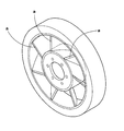
- FIG. 1 is a perspective view showing an embodiment of an airless tire of the present invention. It is sectional drawing of the axial direction. It is a fragmentary perspective view which shows a spoke.
- (A) and (B) are the top views and side views which show notionally the thickness center plane.
- (A), (B) is the top view and side view of a thickness center plane which show the crossing line which a thickness center plane cross
- FIG. 1 is a perspective view which shows the arrangement
- FIG. It is a perspective view of a reference airless tire which improved vibration performance different from the present invention.
- (A), (B) is the top view and side view which show the spoke length in the said reference airless tire.
- an airless tire 1 includes a cylindrical tread ring 2 having a contact surface 2S, a radially inner side of the tread ring 2, and fixed to an axle J (shown in FIG. 2). And a spoke 4 for connecting the tread ring 2 and the hub 3 to each other.
- the airless tire 1 is formed as a tire for a passenger car is shown.
- the tread ring 2 is a portion corresponding to a tread portion in a pneumatic tire.
- the tread ring 2 includes a tread rubber portion 2A and a reinforcing cord layer 2B embedded therein.
- tread rubber portion 2A a rubber composition excellent in frictional force against grounding and wear resistance can be suitably employed.
- tread grooves are formed in various pattern shapes on the ground contact surface 2S, which is the outer peripheral surface of the tread ring 2, in order to impart wet performance.
- the reinforcing cord layer 2B is formed of a belt layer 5 and a band layer 6 placed on the outside or inside in the radial direction. However, it can also be formed by only the belt layer 5 or only the band layer 6.
- the belt layer 5 is formed of one or more, in this example, two belt plies 5A and 5B in which tire cords are arranged at an angle of, for example, 10 to 45 degrees with respect to the tire circumferential direction.
- the rigidity of the tread ring 2 is enhanced by the crossing of the tire cords between the plies.
- the band layer 6 is formed of one or more band plies, in this example, one band ply, in which a tire cord is spirally wound in the tire circumferential direction.
- a steel cord and an organic fiber cord can be used as appropriate.
- organic fiber cords high modulus fibers such as aramid, polyethylene naphthalate (PEN), and polyethylene terephthalate (PET) having high strength and elastic modulus can be suitably used.
- Such a tread ring 2 is formed by vulcanizing a raw tread ring in a vulcanization mold.
- the raw tread ring is, for example, a cylindrical drum on which a sheet-like member for forming the belt layer 5, a sheet-like member for forming the band layer 6, and a sheet-like member for forming the tread rubber portion 2A are sequentially arranged in the circumferential direction It is formed by winding around.
- the hub 3 corresponds to a tire wheel, and in this example, a disk-shaped disk portion 3A fixed to the axle J and a cylindrical shape integrally formed at the radially outer end of the disk portion 3A. And a spoke attachment portion 3B.
- a hub hole 3A1 through which the front end portion Ja of the axle J is inserted is formed in the center of the disk portion 3A.
- a plurality of bolt insertion holes 3A2 are provided around the hub hole 3A1 for fastening the bolts Jb disposed on the axle side with nuts.
- Such a hub 3 is preferably formed of a metal material such as steel, an aluminum alloy, and a magnesium alloy, as in the case of a conventional tire wheel.
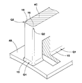
- the spoke 4 is formed by a cast molded body made of a polymer material. As shown in FIGS. 2 and 3, the spoke 4 integrally includes an outer annular portion 4 ⁇ / b> A, an inner annular portion 4 ⁇ / b> B, and a plurality of spoke plate portions 4 ⁇ / b> C having a constant thickness.
- thermosetting resin for example, an epoxy resin, a phenol resin, a urethane resin, a silicon resin, or a polyimide resin.
- Melamine-based resins and the like are preferable.
- urethane-based resins are excellent in elastic properties, and can be more suitably employed.
- the outer annular portion 4A is a cylindrical body concentric with the axle J.
- the outer peripheral surface of the outer annular portion 4A is joined to the inner peripheral surface of the tread ring 2 through, for example, an adhesive.
- the inner annular portion 4B is a cylindrical body arranged concentrically on the radially inner side of the outer annular portion 4A.
- the inner peripheral surface of the inner annular portion 4B is joined to the outer peripheral surface of the hub 3 through, for example, an adhesive.
- the spoke plate 4C integrally connects the outer annular portion 4A and the inner annular portion 4B.
- the thickness center plane S is the radial inner end edge that intersects the outer peripheral surface of the inner annular portion 4B, and the thickness center plane S is the inner peripheral surface of the outer annular portion 4A.
- the intersecting radial outer edge is defined as 8o, the radial inner edge 8i and the radial outer edge 8o are each inclined with respect to the tire axial line.
- the spoke part plate 4C includes a first spoke plate part 4C1 in which the radial inner end edge 8i and the outer end edge 8o are inclined to one side with respect to the tire axial line, and the tire axial line. And the second spoke plate portion 4C2 inclined to the other side.
- first spoke plate portion 4C1 and the second spoke plate portion 4C2 are arranged in a zigzag shape alternately arranged in the circumferential direction.
- the left / right symmetry of the spokes 4 is increased, so that improvement of uniformity and suppression of vehicle flow can be expected.
- the distance D on the one end side where the adjacent first and second spoke plate portions 4C1 and 4C2 are closest to each other is set to be smaller than the ground contact length (not shown) and further 15 mm or less. Is more preferable.
- FIG. 4A and 4B conceptually show a plan view and a side view of the thickness center plane S.
- FIG. As shown in the figure, the inner edge 8i and the outer edge 8o in the radial direction of the thickness center plane S are inclined at angles ⁇ i and ⁇ o with respect to the tire axial line, respectively, and the angles ⁇ i and ⁇ o are ⁇ i ⁇ o. Therefore, the spoke plate portion 4C is formed in a twisted plate shape.
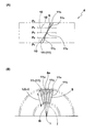
- FIG. 5A and 5B conceptually show a plan view and a side view of the thickness center plane S.
- FIG. As shown in the figure, the intersecting line 11 where the thickness center plane S intersects the plane 10 perpendicular to the tire axial line forms a straight line.
- the spoke length L which is the length from the radially inner end edge 8i to the radially outer end edge 8o along the intersecting line 11, is constant at an arbitrary position in the tire axial direction.
- intersecting lines 11 1 to 11 5 arranged at arbitrary five positions P1 to P5 in the tire axial direction are shown.
- the spoke lengths L1 to L5 of the intersecting lines 11 1 to 11 5 are equal to each other.
- the length of the crossing line 11 (spoke length L) at an arbitrary position in the tire axial direction is constant. Therefore, at the time of rolling, the strain amount at an arbitrary position in the tire axial direction becomes uniform in one spoke plate portion 4C. As a result, stress concentration is suppressed, and damage to the spoke plate portion 4C is suppressed.
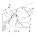
- the intersecting line 11 forms a part of the radiation j extending from the tire axis i at an arbitrary position in the tire axis direction.
- the radially inner end edge 8i includes a first end point E1 on one side in the tire axial direction of the radially inner end edge 8i and a second end point on the other side in the tire axial direction.
- a shortest distance line 12 connecting E2 with the shortest distance along the outer peripheral surface of the inner annular portion 4B is formed.
- the shortest distance line 12 appears as a part of the sine curve 13 when the outer peripheral surface of the inner annular portion 4B is developed on a plane.
- Polymeric material forming the spokes 4 100% tensile stress M 100 is more than 2 MPa, more preferable to use more than a 4 MPa.
- the thickness T of the spoke plate portion 4C is preferably 1 to 5 mm, and the ratio L / T of the spoke length L to the thickness T is preferably 5 to 400.
- the strength of the spoke plate portion 4C is insufficient, and it becomes difficult to ensure sufficient durability.
- the thickness T of the spoke plate portion 4C is less than 1 mm, the spoke plate portion 4C is too thin. As a result, casting molding itself becomes difficult, for example, a poor flow of the polymer material occurs in the mold during casting molding.
- the thickness T exceeds 5 mm, there is no problem in use, but the tire becomes heavy and disadvantageous in fuel efficiency.
- the ratio L / T is less than 5, there is no problem in use.
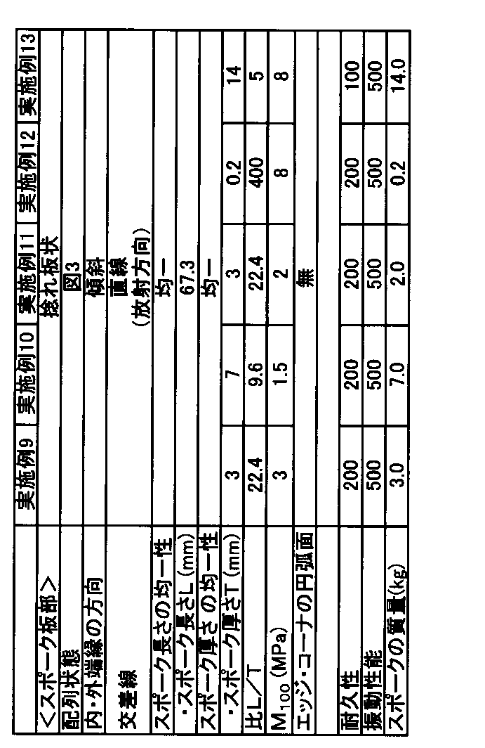
- an airless tire for a passenger car having a structure shown in FIG. 1 (a tire corresponding to a tire size 145 / 70R12) was prototyped based on the specifications shown in Table 1. Then, the durability and vibration performance of each sample tire were tested. Moreover, the mass of the spoke of each sample tire was measured.
- Each tire has substantially the same specifications except those listed in Table 1, and the spoke is integrally formed with the tread ring and the hub by a cast molding method using urethane resin (thermosetting resin).
- urethane resin thermosetting resin
- FIG. 8A shows an arrangement state of the spoke plate portions of Comparative Example 1.
- FIG. 8B shows an arrangement state of the spoke plate portions of Comparative Example 2.
- Comparative Example 2 the inner edge and the outer edge in the radial direction of the thickness center plane of the spoke plate portion are inclined with respect to the tire axial direction as in Examples 1 to 10.
- the angle ⁇ 1 of the inner edge in the radial direction with respect to the tire axial line is the same as the angle ⁇ 1 in Examples 1 to 10.
- the spoke plate portion is formed in a flat plate shape.
- the inner edge in the radial direction of the thickness center plane is formed by the shortest distance line.
- Vibration performance A sample tire is mounted on four wheels of a vehicle (ultra-compact EV: trade name COMS), runs on a tire test course on a dry asphalt road surface, and the vibration performance is displayed as an index with Example 1 as 500 by sensory evaluation of the driver. did. The larger the index, the better the vibration performance.
Landscapes
- Engineering & Computer Science (AREA)
- Mechanical Engineering (AREA)
- Chemical & Material Sciences (AREA)
- Materials Engineering (AREA)
- Tires In General (AREA)
Abstract
Description
前記スポークは、前記トレッドリングの内周面に接合される外側環状部と、前記ハブの外周面に接合される内側環状部と、前記外側環状部と内側環状部とを連結する一定厚さのスポーク板部とを一体に具え、
しかも前記スポーク板部の厚さ中心面が前記内側環状部の外周面と交わる半径方向内端縁、及び厚さ中心面が前記外側環状部の内周面と交わる半径方向外端縁は、それぞれタイヤ軸方向線に対して傾斜するとともに、
前記厚さ中心面がタイヤ軸方向線と直角な面と交わる交差線は直線をなし、かつ該交差線に沿った前記半径方向内端縁から半径方向外端縁までの長さであるスポーク長さLは、タイヤ軸方向の任意の位置において一定であることを特徴としている。
図1に示すように、本実施形態のエアレスタイヤ1は、接地面2Sを有する円筒状のトレッドリング2、前記トレッドリング2の半径方向内側に配されかつ車軸J(図2に示す)に固定されるハブ3、及び前記トレッドリング2とハブ3とを連結するスポーク4を具える。本例では、前記エアレスタイヤ1が乗用車用タイヤとして形成される場合が示される。
(b) 図8(B)に、比較例2のスポーク板部の配列状態が示される。比較例2では、スポーク板部の厚さ中心面の半径方向内端縁及び外端縁は、実施例1~10と同様、タイヤ軸方向に対して傾斜している。又前記半径方向内端縁のタイヤ軸方向線に対する角度θ1は、実施例1~10における角度θ1と同じである。比較例1、2ともスポーク板部は平板状に形成される。
(c) 比較例3は、スポーク板部の配列状態は、実施例1~10におけるスポーク板部の配列状態と同じである。しかし、スポーク板部の厚さTが均一ではなく、タイヤ軸心からの距離に比例して半径方向内端縁側から外端縁側に向かって漸増することのみ相違している。
(d) 実施例3では、交差線が放射線に対して傾斜している。そのため、スポーク長さLが72mmと実施例1、2等に比してやや長い。
ドラム試験機を用い、試供タイヤを、荷重(3kN)、速度(100km/h)にてドラム上を走行させ、タイヤに故障が発生するまでの走行距離を、実施例1を500とする指数で表示した。指数が大きい方が耐久性能に優れている。
試供タイヤを、車両(超小型EV:商品名COMS)の4輪に装着し、ドライアスファルト路面のタイヤテストコースを走行し、振動性能についてドライバーの官能評価により実施例1を500とする指数で表示した。指数が大きい方が振動性能に優れている。
成形前後の質量差から、スポークの質量を換算した。

2 トレッドリング
2S 接地面
3 ハブ
4 スポーク
4A 外側環状部
4B 内側環状部
4C スポーク板部
4C1 第1のスポーク板部
4C2 第2のスポーク板部
8i 半径方向内端縁
8o 半径方向外端縁
10 直角な面
11 交差線
12 最短距離線
E1 第1端点
E2 第2端点
j 放射線
S 厚さ中心面
Claims (5)
- 接地面を有する円筒状のトレッドリング、前記トレッドリングの半径方向内側に配されかつ車軸に固定されるハブ、及び高分子材料による注型成形体からなりかつ前記トレッドリングとハブとを連結するエアレスタイヤであって、
前記スポークは、前記トレッドリングの内周面に接合される外側環状部と、前記ハブの外周面に接合される内側環状部と、前記外側環状部と内側環状部とを連結する一定厚さのスポーク板部とを一体に具え、
しかも前記スポーク板部の厚さ中心面が前記内側環状部の外周面に交わる半径方向内端縁と、前記厚さ中心面が前記外側環状部の内周面に交わる半径方向外端縁とは、それぞれタイヤ軸方向線に対して傾斜するとともに、
前記厚さ中心面がタイヤ軸方向線と直角な面に交わる交差線は直線をなし、かつ該交差線に沿った前記半径方向内端縁から半径方向外端縁までの長さであるスポーク長さLは、タイヤ軸方向の任意の位置において一定であることを特徴とするエアレスタイヤ。 - 前記半径方向内端縁は、この半径方向内端縁のタイヤ軸方向一方側の第1端点と、タイヤ軸方向他方側の第2端点とを前記内側環状部の外周面に沿って最短距離で結ぶ最短距離線をなすことを特徴とする請求項1記載のエアレスタイヤ。
- タイヤ軸方向の任意の位置において、前記交差線は、タイヤ軸心からのびる放射線の一部をなすことを特徴とする請求項1又は2記載のエアレスタイヤ。
- 前記スポーク板部は、前記半径方向内端縁及び外端縁がタイヤ軸方向線に対して一方側に傾斜する第1のスポーク板部と、タイヤ軸方向線に対して他方側に傾斜する第2のスポーク板部とからなり、
しかも前記第1のスポーク板部と第2のスポーク板部とが、周方向に交互に配されることを特徴とする請求項1~3の何れかに記載のエアレスタイヤ。 - 前記高分子材料の100%引張応力M100は2MPa以上、前記スポーク板部の厚さTは1~5mm、かつ前記スポーク長さLと厚さTとの比L/Tは5~400であることを特徴とする請求項1~4の何れかに記載のエアレスタイヤ。
Priority Applications (4)
| Application Number | Priority Date | Filing Date | Title |
|---|---|---|---|
| CN201480065762.8A CN105793063B (zh) | 2013-12-24 | 2014-12-17 | 无气轮胎 |
| US15/103,225 US10399384B2 (en) | 2013-12-24 | 2014-12-17 | Airless tire |
| EP14873785.1A EP3088208B1 (en) | 2013-12-24 | 2014-12-17 | Airless tire |
| KR1020167018260A KR102312792B1 (ko) | 2013-12-24 | 2014-12-17 | 에어리스 타이어 |
Applications Claiming Priority (2)
| Application Number | Priority Date | Filing Date | Title |
|---|---|---|---|
| JP2013265792A JP6212381B2 (ja) | 2013-12-24 | 2013-12-24 | エアレスタイヤ |
| JP2013-265792 | 2013-12-24 |
Publications (1)
| Publication Number | Publication Date |
|---|---|
| WO2015098656A1 true WO2015098656A1 (ja) | 2015-07-02 |
Family
ID=53478520
Family Applications (1)
| Application Number | Title | Priority Date | Filing Date |
|---|---|---|---|
| PCT/JP2014/083428 Ceased WO2015098656A1 (ja) | 2013-12-24 | 2014-12-17 | エアレスタイヤ |
Country Status (6)
| Country | Link |
|---|---|
| US (1) | US10399384B2 (ja) |
| EP (1) | EP3088208B1 (ja) |
| JP (1) | JP6212381B2 (ja) |
| KR (1) | KR102312792B1 (ja) |
| CN (1) | CN105793063B (ja) |
| WO (1) | WO2015098656A1 (ja) |
Cited By (3)
| Publication number | Priority date | Publication date | Assignee | Title |
|---|---|---|---|---|
| EP3159183A1 (en) * | 2015-10-22 | 2017-04-26 | Sumitomo Rubber Industries, Ltd. | Airless tire |
| CN110831782A (zh) * | 2017-06-30 | 2020-02-21 | 米其林集团总公司 | 非充气车轮的边缘防护 |
| CN114801591A (zh) * | 2022-04-20 | 2022-07-29 | 山东玲珑轮胎股份有限公司 | 一种非充气轮胎 |
Families Citing this family (8)
| Publication number | Priority date | Publication date | Assignee | Title |
|---|---|---|---|---|
| JP6750467B2 (ja) * | 2016-11-15 | 2020-09-02 | 住友ゴム工業株式会社 | トレッドリングの剛性測定装置、及びトレッドリングの剛性測定方法 |
| JP6964471B2 (ja) | 2017-09-07 | 2021-11-10 | Toyo Tire株式会社 | 非空気圧タイヤ |
| JP7187102B2 (ja) * | 2019-01-04 | 2022-12-12 | ブリヂストン アメリカズ タイヤ オペレーションズ、 エルエルシー | バンド層を有するタイヤトレッド |
| EP4171970B1 (en) * | 2020-06-29 | 2025-07-30 | Bridgestone Americas Tire Operations, LLC | Non-pneumatic tire having support structure with stress-concentration reduction features |
| KR102412858B1 (ko) | 2020-11-25 | 2022-06-27 | 한국타이어앤테크놀로지 주식회사 | 비공기입 타이어 |
| KR102495966B1 (ko) | 2021-01-18 | 2023-02-06 | 한국타이어앤테크놀로지 주식회사 | 날개를 포함하는 비공기입 타이어 |
| CN113291100B (zh) * | 2021-06-03 | 2024-08-30 | 中国科学院长春应用化学研究所 | 一种非充气轮胎 |
| KR102730030B1 (ko) | 2022-05-04 | 2024-11-14 | 한국타이어앤테크놀로지 주식회사 | 곡부를 구비하는 스포크를 포함하는 비공기입 타이어 |
Citations (4)
| Publication number | Priority date | Publication date | Assignee | Title |
|---|---|---|---|---|
| JP2008055928A (ja) * | 2006-08-29 | 2008-03-13 | Yokohama Rubber Co Ltd:The | 非空気式タイヤ |
| JP2008260514A (ja) | 2007-04-09 | 2008-10-30 | Soc D Technologie Michelin | 非空気圧タイヤ |
| JP2013139253A (ja) * | 2011-12-29 | 2013-07-18 | Hankook Tire Co Ltd | 非空気入りタイヤ |
| WO2014188912A1 (ja) * | 2013-05-22 | 2014-11-27 | 住友ゴム工業株式会社 | エアレスタイヤ、及びその製造方法 |
Family Cites Families (14)
| Publication number | Priority date | Publication date | Assignee | Title |
|---|---|---|---|---|
| JPH02179503A (ja) | 1988-12-29 | 1990-07-12 | Yokohama Rubber Co Ltd:The | 非空気式タイヤ |
| US20040069385A1 (en) * | 2002-07-01 | 2004-04-15 | Sean Timoney | Wheel |
| JP2008132951A (ja) * | 2006-11-29 | 2008-06-12 | Yokohama Rubber Co Ltd:The | 非空気式タイヤ |
| JP2008302782A (ja) * | 2007-06-06 | 2008-12-18 | Yokohama Rubber Co Ltd:The | 非空気入りタイヤ用ホイールおよび非空気入りタイヤ・ホイール組立体 |
| JP4506853B2 (ja) * | 2008-02-25 | 2010-07-21 | 横浜ゴム株式会社 | 非空気式タイヤ |
| US8544515B2 (en) * | 2008-11-10 | 2013-10-01 | Mkp Structural Design Associates, Inc. | Ultralightweight runflat tires based upon negative poisson ratio (NPR) auxetic structures |
| US8991455B2 (en) * | 2011-08-30 | 2015-03-31 | Compagnie Generale Des Etablissements Michelin | Molded article and venting assembly for a rotating mold |
| KR101362120B1 (ko) * | 2011-11-22 | 2014-02-13 | 한국타이어 주식회사 | 에어리스 타이어 |
| JP6159138B2 (ja) * | 2013-05-07 | 2017-07-05 | 住友ゴム工業株式会社 | エアレスタイヤ |
| JP6228604B2 (ja) * | 2013-06-11 | 2017-11-08 | 住友ゴム工業株式会社 | 非空気式タイヤ |
| JP6302355B2 (ja) * | 2014-05-22 | 2018-03-28 | 住友ゴム工業株式会社 | 非空気式タイヤ |
| JP6383294B2 (ja) * | 2015-01-13 | 2018-08-29 | 住友ゴム工業株式会社 | エアレスタイヤ |
| JP6577825B2 (ja) * | 2015-10-26 | 2019-09-18 | 住友ゴム工業株式会社 | エアレスタイヤ、及び、エアレスタイヤ用のハブ部 |
| JP6701997B2 (ja) * | 2016-06-10 | 2020-05-27 | 住友ゴム工業株式会社 | 非空気式タイヤ |
-
2013
- 2013-12-24 JP JP2013265792A patent/JP6212381B2/ja active Active
-
2014
- 2014-12-17 US US15/103,225 patent/US10399384B2/en active Active
- 2014-12-17 EP EP14873785.1A patent/EP3088208B1/en active Active
- 2014-12-17 WO PCT/JP2014/083428 patent/WO2015098656A1/ja not_active Ceased
- 2014-12-17 KR KR1020167018260A patent/KR102312792B1/ko active Active
- 2014-12-17 CN CN201480065762.8A patent/CN105793063B/zh active Active
Patent Citations (4)
| Publication number | Priority date | Publication date | Assignee | Title |
|---|---|---|---|---|
| JP2008055928A (ja) * | 2006-08-29 | 2008-03-13 | Yokohama Rubber Co Ltd:The | 非空気式タイヤ |
| JP2008260514A (ja) | 2007-04-09 | 2008-10-30 | Soc D Technologie Michelin | 非空気圧タイヤ |
| JP2013139253A (ja) * | 2011-12-29 | 2013-07-18 | Hankook Tire Co Ltd | 非空気入りタイヤ |
| WO2014188912A1 (ja) * | 2013-05-22 | 2014-11-27 | 住友ゴム工業株式会社 | エアレスタイヤ、及びその製造方法 |
Cited By (6)
| Publication number | Priority date | Publication date | Assignee | Title |
|---|---|---|---|---|
| EP3159183A1 (en) * | 2015-10-22 | 2017-04-26 | Sumitomo Rubber Industries, Ltd. | Airless tire |
| CN106608145A (zh) * | 2015-10-22 | 2017-05-03 | 住友橡胶工业株式会社 | 无气轮胎 |
| US10406861B2 (en) | 2015-10-22 | 2019-09-10 | Sumitomo Rubber Industries, Ltd. | Airless tire |
| CN106608145B (zh) * | 2015-10-22 | 2021-04-06 | 住友橡胶工业株式会社 | 无气轮胎 |
| CN110831782A (zh) * | 2017-06-30 | 2020-02-21 | 米其林集团总公司 | 非充气车轮的边缘防护 |
| CN114801591A (zh) * | 2022-04-20 | 2022-07-29 | 山东玲珑轮胎股份有限公司 | 一种非充气轮胎 |
Also Published As
| Publication number | Publication date |
|---|---|
| US10399384B2 (en) | 2019-09-03 |
| KR102312792B1 (ko) | 2021-10-15 |
| JP2015120440A (ja) | 2015-07-02 |
| EP3088208B1 (en) | 2020-07-15 |
| JP6212381B2 (ja) | 2017-10-11 |
| KR20160101006A (ko) | 2016-08-24 |
| CN105793063B (zh) | 2017-10-24 |
| EP3088208A1 (en) | 2016-11-02 |
| EP3088208A4 (en) | 2017-08-23 |
| CN105793063A (zh) | 2016-07-20 |
| US20180093527A1 (en) | 2018-04-05 |
Similar Documents
| Publication | Publication Date | Title |
|---|---|---|
| JP6212381B2 (ja) | エアレスタイヤ | |
| US9248697B2 (en) | Airless tire | |
| JP6317633B2 (ja) | エアレスタイヤ | |
| CN105774406B (zh) | 实心轮胎 | |
| KR20170047166A (ko) | 에어리스 타이어 | |
| JP6555405B2 (ja) | エアレスタイヤ | |
| CN101903189A (zh) | 轻型轮胎 | |
| JP2010274799A (ja) | 空気入りタイヤ | |
| JP6347978B2 (ja) | ランフラットタイヤ | |
| JP2004067059A (ja) | 自動二輪車用空気入りタイヤ | |
| JP6577345B2 (ja) | 空気入りタイヤ | |
| JP6331606B2 (ja) | 空気入りタイヤ | |
| JP2013018427A (ja) | 非空気圧タイヤ | |
| JP4819713B2 (ja) | 空気入りタイヤ | |
| JPWO2019244740A1 (ja) | 空気入りタイヤ | |
| JP2021154753A (ja) | 空気入りタイヤ | |
| JP2015085714A (ja) | ランフラットラジアルタイヤ |
Legal Events
| Date | Code | Title | Description |
|---|---|---|---|
| 121 | Ep: the epo has been informed by wipo that ep was designated in this application |
Ref document number: 14873785 Country of ref document: EP Kind code of ref document: A1 |
|
| WWE | Wipo information: entry into national phase |
Ref document number: 15103225 Country of ref document: US |
|
| REG | Reference to national code |
Ref country code: BR Ref legal event code: B01A Ref document number: 112016012544 Country of ref document: BR |
|
| NENP | Non-entry into the national phase |
Ref country code: DE |
|
| REEP | Request for entry into the european phase |
Ref document number: 2014873785 Country of ref document: EP |
|
| WWE | Wipo information: entry into national phase |
Ref document number: 2014873785 Country of ref document: EP |
|
| ENP | Entry into the national phase |
Ref document number: 20167018260 Country of ref document: KR Kind code of ref document: A |
|
| ENP | Entry into the national phase |
Ref document number: 112016012544 Country of ref document: BR Kind code of ref document: A2 Effective date: 20160601 |