WO2015102066A1 - 超音波内視鏡 - Google Patents
超音波内視鏡 Download PDFInfo
- Publication number
- WO2015102066A1 WO2015102066A1 PCT/JP2014/077818 JP2014077818W WO2015102066A1 WO 2015102066 A1 WO2015102066 A1 WO 2015102066A1 JP 2014077818 W JP2014077818 W JP 2014077818W WO 2015102066 A1 WO2015102066 A1 WO 2015102066A1
- Authority
- WO
- WIPO (PCT)
- Prior art keywords
- ultrasonic
- adhesive
- acoustic lens
- opening
- housing
- Prior art date
- Legal status (The legal status is an assumption and is not a legal conclusion. Google has not performed a legal analysis and makes no representation as to the accuracy of the status listed.)
- Ceased
Links
Images


Classifications
-
- A—HUMAN NECESSITIES
- A61—MEDICAL OR VETERINARY SCIENCE; HYGIENE
- A61B—DIAGNOSIS; SURGERY; IDENTIFICATION
- A61B8/00—Diagnosis using ultrasonic, sonic or infrasonic waves
- A61B8/44—Constructional features of the ultrasonic, sonic or infrasonic diagnostic device
- A61B8/4444—Constructional features of the ultrasonic, sonic or infrasonic diagnostic device related to the probe
- A61B8/445—Details of catheter construction
-
- A—HUMAN NECESSITIES
- A61—MEDICAL OR VETERINARY SCIENCE; HYGIENE
- A61B—DIAGNOSIS; SURGERY; IDENTIFICATION
- A61B8/00—Diagnosis using ultrasonic, sonic or infrasonic waves
- A61B8/12—Diagnosis using ultrasonic, sonic or infrasonic waves in body cavities or body tracts, e.g. by using catheters
-
- A—HUMAN NECESSITIES
- A61—MEDICAL OR VETERINARY SCIENCE; HYGIENE
- A61B—DIAGNOSIS; SURGERY; IDENTIFICATION
- A61B8/00—Diagnosis using ultrasonic, sonic or infrasonic waves
- A61B8/42—Details of probe positioning or probe attachment to the patient
- A61B8/4272—Details of probe positioning or probe attachment to the patient involving the acoustic interface between the transducer and the tissue
- A61B8/4281—Details of probe positioning or probe attachment to the patient involving the acoustic interface between the transducer and the tissue characterised by sound-transmitting media or devices for coupling the transducer to the tissue
-
- A—HUMAN NECESSITIES
- A61—MEDICAL OR VETERINARY SCIENCE; HYGIENE
- A61B—DIAGNOSIS; SURGERY; IDENTIFICATION
- A61B8/00—Diagnosis using ultrasonic, sonic or infrasonic waves
- A61B8/44—Constructional features of the ultrasonic, sonic or infrasonic diagnostic device
- A61B8/4444—Constructional features of the ultrasonic, sonic or infrasonic diagnostic device related to the probe
- A61B8/4455—Features of the external shape of the probe, e.g. ergonomic aspects
-
- A—HUMAN NECESSITIES
- A61—MEDICAL OR VETERINARY SCIENCE; HYGIENE
- A61B—DIAGNOSIS; SURGERY; IDENTIFICATION
- A61B8/00—Diagnosis using ultrasonic, sonic or infrasonic waves
- A61B8/44—Constructional features of the ultrasonic, sonic or infrasonic diagnostic device
- A61B8/4483—Constructional features of the ultrasonic, sonic or infrasonic diagnostic device characterised by features of the ultrasound transducer
- A61B8/4494—Constructional features of the ultrasonic, sonic or infrasonic diagnostic device characterised by features of the ultrasound transducer characterised by the arrangement of the transducer elements
-
- A—HUMAN NECESSITIES
- A61—MEDICAL OR VETERINARY SCIENCE; HYGIENE
- A61B—DIAGNOSIS; SURGERY; IDENTIFICATION
- A61B1/00—Instruments for performing medical examinations of the interior of cavities or tubes of the body by visual or photographical inspection, e.g. endoscopes; Illuminating arrangements therefor
- A61B1/00064—Constructional details of the endoscope body
- A61B1/00071—Insertion part of the endoscope body
- A61B1/0008—Insertion part of the endoscope body characterised by distal tip features
- A61B1/00101—Insertion part of the endoscope body characterised by distal tip features the distal tip features being detachable
-
- A—HUMAN NECESSITIES
- A61—MEDICAL OR VETERINARY SCIENCE; HYGIENE
- A61B—DIAGNOSIS; SURGERY; IDENTIFICATION
- A61B1/00—Instruments for performing medical examinations of the interior of cavities or tubes of the body by visual or photographical inspection, e.g. endoscopes; Illuminating arrangements therefor
- A61B1/00064—Constructional details of the endoscope body
- A61B1/0011—Manufacturing of endoscope parts
Definitions
- the present invention relates to an ultrasonic endoscope in which an adhesive is filled in a housing that accommodates an ultrasonic transducer part.
- Some endoscopes used in the medical field include an insertion section that can be introduced into a subject, and an ultrasound transducer section for transmitting and receiving ultrasound at the distal end of the insertion section.
- an ultrasonic endoscope including an ultrasonic transducer unit that can scan an ultrasonic beam.
- the upper surface which is a surface that transmits and receives ultrasonic waves, is covered with an acoustic lens.
- An ultrasonic transducer unit including an acoustic lens is accommodated in a housing which is a casing except for an upper surface where ultrasonic waves are transmitted and received.
- the housing is filled with an adhesive to prevent liquid or gas from entering the housing.
- an adhesive is filled so that no air bubbles remain in the housing in order to improve water tightness and air tightness in the housing that houses the ultrasonic transducer unit including the acoustic lens.
- a hole for discharging bubbles is provided in the housing, it is necessary to provide a location for forming the hole in the housing, which increases the size of the housing.
- An increase in the size of the housing is not preferable because it leads to an increase in the size of the distal end portion of the ultrasonic endoscope.
- the present invention has been made in view of the above-described points, and is an ultrasonic wave that prevents the remaining of bubbles in the housing without enlarging the housing that accommodates the ultrasonic transducer part and is filled with the adhesive.
- An object is to provide an endoscope.
- An ultrasonic endoscope has a rectangular upper surface, and an ultrasonic transducer unit that transmits and receives ultrasonic waves from the upper surface, and one end of which is electrically connected to the ultrasonic transducer unit.
- a quadrangular prism shape by covering the upper surface and the side surface of the ultrasonic transducer section, and at least one corner of the four corners of the quadrangular prism shape when viewed from the direction facing the upper surface
- An acoustic lens having a chamfered portion and an ultrasonic transducer unit including the acoustic lens, the rectangular first opening into which the rectangular prism-shaped acoustic lens is fitted, and the first
- a housing having a second opening for leading the cable out of the one opening, and forming an adhesive outlet that is a gap through which the adhesive flows out between the chamfer and the corner of the first opening; Fill in the housing Is having, an adhesive filling the adhesive outlet to.
- FIG. 5 is a VV cross-sectional view of FIG. 2. It is a figure which shows the upper surface of an ultrasonic transducer
- the ultrasonic endoscope 1 of the present embodiment shown in FIG. 1 electronically scans an ultrasonic beam in a subject, thereby obtaining an ultrasonic tomographic image (B mode image) of a predetermined part in the subject. It is a device to obtain.
- the ultrasonic endoscope 1 includes an insertion portion 2 that can be introduced into the body of a subject, an operation portion 3 that is located at the proximal end of the insertion portion 2, and a universal cord 4 that extends from a side portion of the operation portion 3. Has mainly composed.
- the insertion portion 2 includes a distal end portion 10 disposed at the distal end, a bendable bending portion 11 disposed on the proximal end side of the distal end portion 10, and a proximal end side of the bending portion 11.
- a flexible tube portion 12 having flexibility and connected to the distal end side is continuously provided.
- the ultrasonic endoscope 1 may have a form called a so-called rigid endoscope that does not have a flexible portion in the insertion portion 2.
- the distal end portion 10 of the insertion portion 2 includes an imaging device, an illumination device, and a treatment tool for capturing an optical image (not shown), in addition to an ultrasonic transducer unit 20 that will be described in detail later.
- a treatment instrument insertion port or the like for projecting is provided.
- the operation section 3 is provided with an angle operation knob 13 for operating the bending of the bending section 11.
- the operation unit 3 is provided with a switch or the like for controlling the operation of sending out the fluid from the opening provided in the tip 10 and the suction operation.
- An endoscope connector 4a connected to a light source device is provided at the base end of the universal cord 4.
- the light emitted from the light source device travels through the optical fiber cable inserted through the universal cord 4, the operation unit 3, and the insertion unit 2, and is emitted from the illumination device at the tip 10.
- the ultrasonic endoscope 1 may have a configuration in which a light source device such as an LED is provided in the illumination device disposed at the distal end portion 10.
- the electric cable 5 and the ultrasonic cable 6 extend from the endoscope connector 4a.
- the electric cable 5 is detachably connected to a camera control unit (not shown) via an electric connector 5a.
- the camera control unit is a device that outputs an image captured by the imaging device provided at the distal end portion 10 to the image display device 8.
- the ultrasonic cable 6 is detachably connected to the ultrasonic observation control device 7 via the ultrasonic connector 6a.
- the ultrasonic connector 6 a is electrically connected to a plurality of transducer elements 22, which will be described later, included in the ultrasonic transducer unit 20 via the cable 21 inserted through the ultrasonic cable 6, the universal cord 4, the operation unit 3, and the insertion unit 2. Connected.
- the ultrasonic observation control device 7 is a device that controls the transmission / reception operation of ultrasonic waves by the ultrasonic transducer unit 20 and generates an ultrasonic tomographic image, and outputs the ultrasonic tomographic image to the image display device 8. Note that the ultrasonic endoscope 1 may not include the ultrasonic observation control device 7 and the image display device 8.
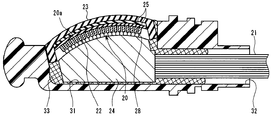
- the ultrasonic transducer part 20 is held by the housing 30 at the distal end part 10 of the insertion part 3.
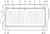
- FIG. 2 is a view showing the top surfaces of the ultrasonic transducer section 20 and the housing 30.
- FIG. 3 is a view showing a side surface of the housing 30.
- 4 is a cross-sectional view taken along the line IV-IV in FIG.
- FIG. 5 is a cross-sectional view taken along the line V-V in FIG.
- the ultrasonic transducer section 20 is composed of a plurality of transducer elements 22 arranged in one row.
- the surface of the ultrasonic transducer unit 20 that transmits and receives ultrasonic waves is referred to as an upper surface 20a, and the opposite surface is referred to as a lower surface.
- a surface intersecting the upper surface 20a and the lower surface is referred to as a side surface.
- the transducer elements 22 may be arranged in a plurality of rows.
- the vibrator element 22 is a piezoelectric element or an electrostrictive element that mutually converts an electric signal and an ultrasonic wave, or an ultrasonic transducer (MUT; Micromachined Transducer) using a micromachine technology.
- MUT Micromachined Transducer
- the vibrator element 22 is a piezoelectric element made of a piezoelectric material, and has an upper electrode 22a and a lower electrode 22b arranged with the piezoelectric material interposed therebetween as shown in FIG.
- the upper electrode 22a is disposed on the upper surface 20a side of the ultrasonic transducer section 20, and the lower electrode 22b is disposed on the lower surface side.
- the vibrator element 22 is deformed so as to expand and contract in a direction sandwiched between the upper electrode 22a and the lower electrode 22b according to a voltage applied between the upper electrode 22a and the lower electrode 22b.
- the surface of the lower electrode 22b opposite to the piezoelectric element is in contact with a backing material 26 made of a non-conductive material.
- the backing material 26 is a synthetic resin that is cured after being filled in a holding frame 29 that surrounds the side surface of the ultrasonic transducer section 20.
- the backing material 26 is a member that absorbs ultrasonic waves radiated from the lower electrode 22b side of the transducer element 22 and ultrasonic waves directed from the inside of the distal end portion 10 toward the transducer element 22. For this reason, in the present embodiment, transmission / reception of ultrasonic waves by the transducer element 22 is performed on the upper surface 20a side where the upper electrode 22a is provided.
- the upper surface 20a of the ultrasonic transducer section 20 is curved into a convex cylindrical surface shape toward the outside (upward).
- the plurality of transducer elements 22 constituting the ultrasonic transducer section 20 are arranged in a line along the circumferential direction of the upper surface 20a.
- the upper surface 20a of the ultrasonic transducer section 20 has a rectangular shape when viewed from the direction along the normal line of the upper surface 20a.
- the case of viewing from the direction along the normal line of the upper surface 20a is the case of viewing from the direction facing the upper surface 20a of the ultrasonic transducer section 20, as shown in FIG.
- the plurality of transducer elements 22 are arranged in a line along the longitudinal direction of the upper surface 20a of the ultrasonic transducer section 20 having a rectangular shape.
- the upper surface 20a of the ultrasonic transducer section 20 is curved along the cylindrical surface and has a rectangular shape with the circumferential direction of the cylindrical surface as the longitudinal direction.
- the ultrasonic transducer section 20 can transmit an ultrasonic beam in a direction (radial direction) along the normal line of the cylindrical surface, and can scan the ultrasonic beam in the circumferential direction.
- the ultrasonic endoscope 1 having such an ultrasonic transducer section 20 is generally referred to as an electronic scanning convex ultrasonic endoscope.
- the scanning format of the ultrasonic beam by the ultrasonic transducer section 20 is not limited to this embodiment, and is a linear format in which the upper surface 20a is planar and a plurality of transducer elements 22 are arranged linearly. May be.
- the upper electrode 22a of the transducer element 22 is a ground electrode that is set to a ground potential
- the lower electrode 22b is a signal electrode for inputting and outputting voltage signals.
- the upper electrode 22a is electrically connected to the cable 21 via the ground potential wiring 27 as shown in FIG.
- the lower electrode 22 b is electrically connected to the cable 21 via the signal wiring 28 and the circuit board 24.
- the circuit board 24 and the transducer element 22 are fixed by a backing material 26.
- An acoustic matching layer 25 is disposed on the upper surface 20 a of the ultrasonic transducer section 20.
- the acoustic matching layer 25 is a member that performs acoustic impedance matching between the transducer element 22 and an acoustic lens 23 described later.
- the acoustic matching layer 25 is appropriately provided according to the difference in acoustic impedance between the transducer element 22 and the acoustic lens 23. Therefore, for example, it is not necessary when the difference in acoustic impedance between the transducer element 22 and the acoustic lens 23 is small.
- the acoustic matching layer 25 may be formed by stacking a plurality of layers made of different materials in the thickness direction, or may be a single layer.
- the acoustic lens 23 is a member that covers the upper surface 20a and side surfaces of the ultrasonic transducer section 20.
- the acoustic lens 23 is made of a nonconductive material such as silicone.
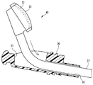
- FIG. 6 is a view of the ultrasonic transducer unit 20 and the top surface of the acoustic lens 23 that covers the ultrasonic transducer unit 20.
- FIG. 7 is a view of the side surface of the ultrasonic transducer unit 20 and the acoustic lens 23 covering the ultrasonic transducer unit 20.
- the acoustic lens 23 forms a quadrangular prism shape by covering the upper surface 20a and side surfaces of the ultrasonic transducer section 20. More specifically, when viewed from the direction facing the upper surface 20a, the outer shape of the acoustic lens 23 has a rectangular shape with the arrangement direction of the transducer elements 22 as the longitudinal direction.
- a chamfered portion 23a is formed by cutting off the corner.
- the chamfered portion 23 a is formed over the entire corner ridgeline of the acoustic lens 23.
- the chamfered portions 23 a are formed at all four corners of the outer shape of the acoustic lens 23.
- the chamfered portion 23a has an angle ⁇ of less than 45 degrees with respect to the long side of the upper surface of the acoustic lens 23 that is rectangular when viewed from the direction facing the upper surface 20a. That is, in the chamfered portion 23a, the angle ⁇ with respect to the side parallel to the arrangement direction of the transducer elements 22 on the upper surface of the acoustic lens 23 is less than 45 degrees.
- the shape of the portion cut off by the chamfered portion 23a of the acoustic lens 23 is the length L1 of the side parallel to the arrangement direction of the transducer elements 22, It becomes a right triangle longer than the length L2 of the side orthogonal to the side of the length L1.
- the short side of the upper surface 20a when viewed from the direction facing the upper surface 20a is formed by making the right triangle portion cut off by the chamfered portion 23a elongated in the arrangement direction of the transducer elements 22.
- the ratio of the chamfered portion 23a in the length of the can be reduced. Thereby, interference between the chamfered portion 23a and the transducer element 22 can be avoided, and an increase in the length of the short side of the acoustic lens 23 due to the provision of the chamfered portion 23a can be prevented.
- the ultrasonic transducer unit 20 When the ultrasonic endoscope 1 is assembled, as shown in FIGS. 6 and 7, the ultrasonic transducer unit 20 is connected to the tip of the cable 21, and the acoustic lens 23 is fixed to the ultrasonic transducer unit 20. An ultrasonic unit 40 is produced. And this ultrasonic unit 40 is stored in the housing 30 mentioned later, and is fixed.
- the housing 30 is a housing having a space for accommodating the ultrasonic unit 40 therein.
- a first opening 31 that exposes an upper surface of the acoustic lens 23 that transmits ultrasonic waves of the ultrasonic transducer unit 20 to the outside and a cable 21 connected to the ultrasonic transducer unit 20 are led out.
- a second opening 32 is formed.
- the acoustic lens 23 and the ultrasonic transducer unit 20 accommodated in the housing 30 are fixed by an adhesive 33 filled in the housing 30.
- the first opening 31 is a rectangular hole into which the acoustic lens 23 having a quadrangular prism shape is fitted with a predetermined gap. As shown in FIG. 8, when the acoustic lens 23 is fitted in the first opening 31, a gap is generated between the outer peripheral surface of the acoustic lens 23 and the inner peripheral surface of the first opening 31.
- an adhesive outlet 34 that is a right-angled triangular gap is provided between the chamfered portion 23 a and the corner of the first opening 31. It is formed.
- the shape of the adhesive outlet 34 is a right triangle that is elongated in the arrangement direction of the transducer elements 22 when viewed from the direction facing the upper surface 20a.
- the gap between the outer peripheral surface of the acoustic lens 23 including the adhesive outlet 34 and the inner peripheral surface of the first opening 31 is filled with an adhesive 33.
- the second opening 32 is a through-hole that communicates the first opening 31 and the outside of the housing 30, and the cable 21 that is a bundle of a plurality of coaxial wires is inserted with a predetermined gap.
- the total sectional area of the gap between the outer peripheral surface of the acoustic lens 23 and the inner peripheral surface of the first opening 31 is the total sectional area of the gap generated between the second opening 32 and the cable 21.
- the uncured adhesive 33 filled in the housing 30 is likely to flow out of the gaps of the first openings 31 and is difficult to flow out from the second openings 32 side. Therefore, the amount of the adhesive 33 flowing out from the second opening 32 along the cable 21 can be suppressed, and the bending of the cable 21 can be prevented from being hindered by the cured adhesive 33.
- the cable 21 is inserted into the second opening 32 from the first opening 31 side of the housing 30.
- the inside of the first opening 31 of the housing 30 is filled with the defoamed adhesive 33 before curing.
- the adhesive agent 33 in the state before hardening after defoaming is shown by the hatching of the hatching.
- the adhesive 33 has a viscosity that is difficult to flow out of the gap between the second opening 32 and the cable 21 due to gravity.
- the ultrasonic transducer unit 20 and the acoustic lens 23 are inserted into the first opening 31 filled with the adhesive 33.
- the adhesive 33 is mainly from the gap generated in the first opening 31. leak.
- the adhesive 33 flows out from a gap generated on the entire outer peripheral surface of the acoustic lens 23, the gap between the outer peripheral surface of the acoustic lens 23 and the inner peripheral surface of the first opening 31 is caused by the adhesive 33. Filled and no bubbles remain.
- the ultrasonic transducer unit 20 and the acoustic lens 23 are inserted into the first opening 31 so as to push out the adhesive 33, thereby The bubbles are discharged together with the adhesive 33 to the outside of the housing 30.
- the adhesive outlet 34 having a wide gap is formed, the bubbles are easily discharged together with the adhesive 33 without being caught. Further, since the flowing out adhesive 33 has a flow toward the adhesive outlet 34, air bubbles sandwiched between the acoustic lens 23 and the lower surface of the ultrasonic transducer unit 20 and the adhesive 33 are also bonded to the adhesive 33. At the same time, it is discharged from the adhesive outlet 34 to the outside of the housing 30.
- the adhesive agent 33 in the 1st opening part 31 can be made to flow out evenly by forming the adhesive agent outlet 34 in all the four corners of the 1st opening part 31 which is rectangular shape. It is possible to eliminate the portion where the adhesive 33 is likely to stagnate. That is, according to the present embodiment, it is possible to eliminate a portion where bubbles in the housing 30 easily remain.
- the adhesive 33 that has flowed out is wiped off, the adhesive 33 is cured, so that the ultrasonic unit 40 is fixed in the housing 30.
- the adhesive outlet 34 that allows the adhesive 33 to flow out is formed between the first opening 31 of the housing 30 and the acoustic lens 23. ing. By forming the adhesive outlet 34, air bubbles can be prevented from remaining in the housing 30 after the adhesive 33 is cured.
- the adhesive outlet 34 is formed by providing the chamfered portion 23 a at the corner of the acoustic lens 23, it can be provided without increasing the opening area of the first opening 31. is there. Therefore, in this embodiment, without increasing the size of the housing 30, the bubbles of the adhesive 33 filled in the housing 30 can be easily discharged, and the bubbles can be prevented from remaining.
- the adhesive outlet 34 is a right-angled triangle that is elongated in the arrangement direction of the transducer elements 22, thereby preventing the presence of the adhesive outlet 34 from interfering with the dimensions of the transducer elements 22. is doing. Therefore, in the present embodiment, it is possible to provide the adhesive outlet 34 without increasing the size of the housing 30 and without decreasing the size of the transducer element 22.
- bubbles remain in the housing 30 without enlarging the housing 30 containing the ultrasonic transducer unit 20 and the acoustic lens 23 and filled with the adhesive 33.
- An ultrasonic endoscope 1 without the above is realized.
Landscapes
- Health & Medical Sciences (AREA)
- Life Sciences & Earth Sciences (AREA)
- Physics & Mathematics (AREA)
- Heart & Thoracic Surgery (AREA)
- Molecular Biology (AREA)
- Nuclear Medicine, Radiotherapy & Molecular Imaging (AREA)
- Pathology (AREA)
- Radiology & Medical Imaging (AREA)
- Engineering & Computer Science (AREA)
- Biomedical Technology (AREA)
- Veterinary Medicine (AREA)
- Medical Informatics (AREA)
- Biophysics (AREA)
- Surgery (AREA)
- Animal Behavior & Ethology (AREA)
- General Health & Medical Sciences (AREA)
- Public Health (AREA)
- Acoustics & Sound (AREA)
- Gynecology & Obstetrics (AREA)
- Ultra Sonic Daignosis Equipment (AREA)
Abstract
Description
Claims (3)
- 矩形形状の上面を有し、前記正面から超音波を送受信する超音波振動子部と、
一端が前記超音波振動子部に電気的に接続されているケーブルと、
前記超音波振動子部の前記上面及び側面を覆うことで四角柱形状を形成し、前記上面に対向する方向から見た場合における前記四角柱形状の四隅のうち少なくとも1つの角を切り落とした面取り部を有する音響レンズと、
超音波振動子部を及び前記音響レンズを収容する筐体であって、前記四角柱形状の音響レンズが嵌め込まれる矩形形状の第1開口部、及び前記第1開口部内から前記ケーブルを導出する第2開口部を有し、前記面取り部と前記第1開口部の角との間に接着剤を流出する隙間である接着剤流出口を形成するハウジングと、
前記ハウジング内に充填されて前記接着剤流出口を満たす接着剤と、
を有することを特徴とする超音波内視鏡。 - 前記超音波振動子部は、複数の振動子素子を前記上面に沿って一列に並べて成り、
前記接着剤流出口の形状は、前記振動子素子の配列方向に細長な直角三角形であることを特徴とする請求項1に記載の超音波内視鏡。 - 前記接着剤流出口を含む前記第1開口部と前記音響レンズとの隙間の断面積は、前記第2開口部と前記ケーブルとの隙間の断面積よりも大きいことを特徴とする請求項1又は2に記載の超音波内視鏡。
Priority Applications (4)
| Application Number | Priority Date | Filing Date | Title |
|---|---|---|---|
| JP2015528781A JP5792422B6 (ja) | 2014-01-06 | 2014-10-20 | 超音波内視鏡 |
| CN201480025149.3A CN105163668B (zh) | 2014-01-06 | 2014-10-20 | 超声波内窥镜 |
| EP14877415.1A EP2982308B8 (en) | 2014-01-06 | 2014-10-20 | Ultrasound endoscope |
| US14/931,113 US9517052B2 (en) | 2014-01-06 | 2015-11-03 | Ultrasound endoscope |
Applications Claiming Priority (2)
| Application Number | Priority Date | Filing Date | Title |
|---|---|---|---|
| JP2014-000467 | 2014-01-06 | ||
| JP2014000467 | 2014-01-06 |
Related Child Applications (1)
| Application Number | Title | Priority Date | Filing Date |
|---|---|---|---|
| US14/931,113 Continuation US9517052B2 (en) | 2014-01-06 | 2015-11-03 | Ultrasound endoscope |
Publications (1)
| Publication Number | Publication Date |
|---|---|
| WO2015102066A1 true WO2015102066A1 (ja) | 2015-07-09 |
Family
ID=53493411
Family Applications (1)
| Application Number | Title | Priority Date | Filing Date |
|---|---|---|---|
| PCT/JP2014/077818 Ceased WO2015102066A1 (ja) | 2014-01-06 | 2014-10-20 | 超音波内視鏡 |
Country Status (4)
| Country | Link |
|---|---|
| US (1) | US9517052B2 (ja) |
| EP (1) | EP2982308B8 (ja) |
| CN (1) | CN105163668B (ja) |
| WO (1) | WO2015102066A1 (ja) |
Families Citing this family (12)
| Publication number | Priority date | Publication date | Assignee | Title |
|---|---|---|---|---|
| DE112016006633T5 (de) * | 2016-03-23 | 2018-12-06 | Olympus Corporation | Endoskop |
| EP3628208A1 (en) | 2018-09-28 | 2020-04-01 | Ambu A/S | An articulated tip part for an endoscope |
| EP3628205A1 (en) | 2018-09-28 | 2020-04-01 | Ambu A/S | A method for manufacture of a tip part and a tip part for an endoscope |
| EP3628206B1 (en) * | 2018-09-28 | 2023-05-03 | Ambu A/S | A method for manufacture of a tip part and a tip part for an endoscope |
| EP3636133B1 (en) | 2018-10-12 | 2024-04-03 | Ambu A/S | An articulated tip part for an endoscope |
| US12575721B2 (en) | 2019-05-01 | 2026-03-17 | Ambu A/S | Devices, systems, and methods for treating kidney stones |
| US11945144B2 (en) | 2019-09-06 | 2024-04-02 | Ambu A/S | Tip part assembly for an endoscope |
| EP3964116A1 (en) | 2020-09-02 | 2022-03-09 | Ambu A/S | Endoscope tip part |
| EP3988006B1 (en) | 2020-10-20 | 2023-08-09 | Ambu A/S | An endoscope |
| EP4011270A1 (en) | 2020-12-08 | 2022-06-15 | Ambu A/S | Endoscope tip part with improved optical properties |
| CN114583042A (zh) * | 2022-03-16 | 2022-06-03 | 河南翔宇医疗设备股份有限公司 | 一种压电换能器和医疗设备 |
| EP4292511A1 (en) * | 2022-06-17 | 2023-12-20 | Ambu A/S | An endoscope |
Citations (4)
| Publication number | Priority date | Publication date | Assignee | Title |
|---|---|---|---|---|
| JPS6173639A (ja) * | 1984-09-17 | 1986-04-15 | オリンパス光学工業株式会社 | 超音波内視鏡のヘツド装置 |
| JPH0975345A (ja) | 1995-09-12 | 1997-03-25 | Fuji Photo Optical Co Ltd | 超音波検査装置 |
| JP5185476B2 (ja) * | 2011-05-13 | 2013-04-17 | オリンパスメディカルシステムズ株式会社 | 超音波振動子ユニット、超音波内視鏡 |
| JP5253691B1 (ja) * | 2011-09-09 | 2013-07-31 | オリンパスメディカルシステムズ株式会社 | 超音波内視鏡 |
Family Cites Families (1)
| Publication number | Priority date | Publication date | Assignee | Title |
|---|---|---|---|---|
| US5176140A (en) * | 1989-08-14 | 1993-01-05 | Olympus Optical Co., Ltd. | Ultrasonic probe |
-
2014
- 2014-10-20 EP EP14877415.1A patent/EP2982308B8/en active Active
- 2014-10-20 WO PCT/JP2014/077818 patent/WO2015102066A1/ja not_active Ceased
- 2014-10-20 CN CN201480025149.3A patent/CN105163668B/zh active Active
-
2015
- 2015-11-03 US US14/931,113 patent/US9517052B2/en active Active
Patent Citations (4)
| Publication number | Priority date | Publication date | Assignee | Title |
|---|---|---|---|---|
| JPS6173639A (ja) * | 1984-09-17 | 1986-04-15 | オリンパス光学工業株式会社 | 超音波内視鏡のヘツド装置 |
| JPH0975345A (ja) | 1995-09-12 | 1997-03-25 | Fuji Photo Optical Co Ltd | 超音波検査装置 |
| JP5185476B2 (ja) * | 2011-05-13 | 2013-04-17 | オリンパスメディカルシステムズ株式会社 | 超音波振動子ユニット、超音波内視鏡 |
| JP5253691B1 (ja) * | 2011-09-09 | 2013-07-31 | オリンパスメディカルシステムズ株式会社 | 超音波内視鏡 |
Also Published As
| Publication number | Publication date |
|---|---|
| EP2982308B1 (en) | 2019-07-24 |
| CN105163668A (zh) | 2015-12-16 |
| EP2982308B8 (en) | 2019-09-11 |
| US9517052B2 (en) | 2016-12-13 |
| EP2982308A1 (en) | 2016-02-10 |
| US20160051222A1 (en) | 2016-02-25 |
| CN105163668B (zh) | 2017-09-15 |
| JP5792422B1 (ja) | 2015-10-14 |
| JPWO2015102066A1 (ja) | 2017-03-23 |
| EP2982308A4 (en) | 2017-04-05 |
Similar Documents
| Publication | Publication Date | Title |
|---|---|---|
| CN105163668B (zh) | 超声波内窥镜 | |
| US9924925B2 (en) | Ultrasound transducer and ultrasound probe | |
| US8198787B2 (en) | Ultrasonic probe with adhesive protrusion preventive structure | |
| CN107205726B (zh) | 超声波探头 | |
| CN107708576B (zh) | 超声波振子和超声波探头 | |
| EP3449841A1 (en) | Ultrasonic vibrator unit | |
| CN110381847A (zh) | 超声波振子、超声波内窥镜以及超声波振子的制造方法 | |
| CN109561884B (zh) | 超声波振子组件的制造方法及超声波内窥镜 | |
| JP5876196B1 (ja) | 超音波内視鏡 | |
| US10869649B2 (en) | Ultrasound transducer module and ultrasound endoscope | |
| CN109475348B (zh) | 超声波振子组件、超声波内窥镜以及超声波振子组件的制造方法 | |
| JP5792422B6 (ja) | 超音波内視鏡 | |
| US11369344B2 (en) | Ultrasound transducer and ultrasound endoscope | |
| CN111656799B (zh) | 超声波探头 | |
| US20190133555A1 (en) | Ultrasonic transducer module and ultrasonic endoscope | |
| JP2018064744A (ja) | 超音波振動子、超音波内視鏡、及び超音波振動子の製造方法 |
Legal Events
| Date | Code | Title | Description |
|---|---|---|---|
| WWE | Wipo information: entry into national phase |
Ref document number: 201480025149.3 Country of ref document: CN |
|
| ENP | Entry into the national phase |
Ref document number: 2015528781 Country of ref document: JP Kind code of ref document: A |
|
| 121 | Ep: the epo has been informed by wipo that ep was designated in this application |
Ref document number: 14877415 Country of ref document: EP Kind code of ref document: A1 |
|
| WWE | Wipo information: entry into national phase |
Ref document number: 2014877415 Country of ref document: EP |
|
| NENP | Non-entry into the national phase |
Ref country code: DE |