WO2015105073A1 - 排ガス処理装置、船舶、水供給方法 - Google Patents
排ガス処理装置、船舶、水供給方法 Download PDFInfo
- Publication number
- WO2015105073A1 WO2015105073A1 PCT/JP2015/050053 JP2015050053W WO2015105073A1 WO 2015105073 A1 WO2015105073 A1 WO 2015105073A1 JP 2015050053 W JP2015050053 W JP 2015050053W WO 2015105073 A1 WO2015105073 A1 WO 2015105073A1
- Authority
- WO
- WIPO (PCT)
- Prior art keywords
- water
- exhaust gas
- scrubber
- drain
- line
- Prior art date
- Legal status (The legal status is an assumption and is not a legal conclusion. Google has not performed a legal analysis and makes no representation as to the accuracy of the status listed.)
- Ceased
Links
Images
Classifications
-
- B—PERFORMING OPERATIONS; TRANSPORTING
- B01—PHYSICAL OR CHEMICAL PROCESSES OR APPARATUS IN GENERAL
- B01D—SEPARATION
- B01D47/00—Separating dispersed particles from gases, air or vapours by liquid as separating agent
- B01D47/10—Venturi scrubbers
-
- B—PERFORMING OPERATIONS; TRANSPORTING
- B01—PHYSICAL OR CHEMICAL PROCESSES OR APPARATUS IN GENERAL
- B01D—SEPARATION
- B01D53/00—Separation of gases or vapours; Recovering vapours of volatile solvents from gases; Chemical or biological purification of waste gases, e.g. engine exhaust gases, smoke, fumes, flue gases, aerosols
- B01D53/14—Separation of gases or vapours; Recovering vapours of volatile solvents from gases; Chemical or biological purification of waste gases, e.g. engine exhaust gases, smoke, fumes, flue gases, aerosols by absorption
- B01D53/1456—Removing acid components
- B01D53/1481—Removing sulfur dioxide or sulfur trioxide
-
- B—PERFORMING OPERATIONS; TRANSPORTING
- B63—SHIPS OR OTHER WATERBORNE VESSELS; RELATED EQUIPMENT
- B63H—MARINE PROPULSION OR STEERING
- B63H21/00—Use of propulsion power plant or units on vessels
- B63H21/32—Arrangements of propulsion power-unit exhaust uptakes; Funnels peculiar to vessels
-
- F—MECHANICAL ENGINEERING; LIGHTING; HEATING; WEAPONS; BLASTING
- F01—MACHINES OR ENGINES IN GENERAL; ENGINE PLANTS IN GENERAL; STEAM ENGINES
- F01N—GAS-FLOW SILENCERS OR EXHAUST APPARATUS FOR MACHINES OR ENGINES IN GENERAL; GAS-FLOW SILENCERS OR EXHAUST APPARATUS FOR INTERNAL-COMBUSTION ENGINES
- F01N3/00—Exhaust or silencing apparatus having means for purifying, rendering innocuous, or otherwise treating exhaust
- F01N3/02—Exhaust or silencing apparatus having means for purifying, rendering innocuous, or otherwise treating exhaust for cooling, or for removing solid constituents of, exhaust
- F01N3/04—Exhaust or silencing apparatus having means for purifying, rendering innocuous, or otherwise treating exhaust for cooling, or for removing solid constituents of, exhaust using liquids
-
- F—MECHANICAL ENGINEERING; LIGHTING; HEATING; WEAPONS; BLASTING
- F02—COMBUSTION ENGINES; HOT-GAS OR COMBUSTION-PRODUCT ENGINE PLANTS
- F02B—INTERNAL-COMBUSTION PISTON ENGINES; COMBUSTION ENGINES IN GENERAL
- F02B29/00—Engines characterised by provision for charging or scavenging not provided for in groups F02B25/00, F02B27/00 or F02B33/00 - F02B39/00; Details thereof
- F02B29/04—Cooling of air intake supply
- F02B29/045—Constructional details of the heat exchangers, e.g. pipes, plates, ribs, insulation, materials, or manufacturing and assembly
- F02B29/0468—Water separation or drainage means
-
- F—MECHANICAL ENGINEERING; LIGHTING; HEATING; WEAPONS; BLASTING
- F02—COMBUSTION ENGINES; HOT-GAS OR COMBUSTION-PRODUCT ENGINE PLANTS
- F02M—SUPPLYING COMBUSTION ENGINES IN GENERAL WITH COMBUSTIBLE MIXTURES OR CONSTITUENTS THEREOF
- F02M26/00—Engine-pertinent apparatus for adding exhaust gases to combustion-air, main fuel or fuel-air mixture, e.g. by exhaust gas recirculation [EGR] systems
- F02M26/13—Arrangement or layout of EGR passages, e.g. in relation to specific engine parts or for incorporation of accessories
- F02M26/35—Arrangement or layout of EGR passages, e.g. in relation to specific engine parts or for incorporation of accessories with means for cleaning or treating the recirculated gases, e.g. catalysts, condensate traps, particle filters or heaters
-
- F—MECHANICAL ENGINEERING; LIGHTING; HEATING; WEAPONS; BLASTING
- F02—COMBUSTION ENGINES; HOT-GAS OR COMBUSTION-PRODUCT ENGINE PLANTS
- F02M—SUPPLYING COMBUSTION ENGINES IN GENERAL WITH COMBUSTIBLE MIXTURES OR CONSTITUENTS THEREOF
- F02M26/00—Engine-pertinent apparatus for adding exhaust gases to combustion-air, main fuel or fuel-air mixture, e.g. by exhaust gas recirculation [EGR] systems
- F02M26/13—Arrangement or layout of EGR passages, e.g. in relation to specific engine parts or for incorporation of accessories
- F02M26/36—Arrangement or layout of EGR passages, e.g. in relation to specific engine parts or for incorporation of accessories with means for adding fluids other than exhaust gas to the recirculation passage; with reformers
-
- B—PERFORMING OPERATIONS; TRANSPORTING
- B01—PHYSICAL OR CHEMICAL PROCESSES OR APPARATUS IN GENERAL
- B01D—SEPARATION
- B01D2252/00—Absorbents, i.e. solvents and liquid materials for gas absorption
- B01D2252/10—Inorganic absorbents
- B01D2252/103—Water
-
- B—PERFORMING OPERATIONS; TRANSPORTING
- B01—PHYSICAL OR CHEMICAL PROCESSES OR APPARATUS IN GENERAL
- B01D—SEPARATION
- B01D2257/00—Components to be removed
- B01D2257/40—Nitrogen compounds
- B01D2257/404—Nitrogen oxides other than dinitrogen oxide
-
- B—PERFORMING OPERATIONS; TRANSPORTING
- B01—PHYSICAL OR CHEMICAL PROCESSES OR APPARATUS IN GENERAL
- B01D—SEPARATION
- B01D2259/00—Type of treatment
- B01D2259/45—Gas separation or purification devices adapted for specific applications
- B01D2259/4566—Gas separation or purification devices adapted for specific applications for use in transportation means
-
- F—MECHANICAL ENGINEERING; LIGHTING; HEATING; WEAPONS; BLASTING
- F01—MACHINES OR ENGINES IN GENERAL; ENGINE PLANTS IN GENERAL; STEAM ENGINES
- F01N—GAS-FLOW SILENCERS OR EXHAUST APPARATUS FOR MACHINES OR ENGINES IN GENERAL; GAS-FLOW SILENCERS OR EXHAUST APPARATUS FOR INTERNAL-COMBUSTION ENGINES
- F01N2590/00—Exhaust or silencing apparatus adapted to particular use, e.g. for military applications, airplanes, submarines
- F01N2590/02—Exhaust or silencing apparatus adapted to particular use, e.g. for military applications, airplanes, submarines for marine vessels or naval applications
-
- F—MECHANICAL ENGINEERING; LIGHTING; HEATING; WEAPONS; BLASTING
- F02—COMBUSTION ENGINES; HOT-GAS OR COMBUSTION-PRODUCT ENGINE PLANTS
- F02M—SUPPLYING COMBUSTION ENGINES IN GENERAL WITH COMBUSTIBLE MIXTURES OR CONSTITUENTS THEREOF
- F02M26/00—Engine-pertinent apparatus for adding exhaust gases to combustion-air, main fuel or fuel-air mixture, e.g. by exhaust gas recirculation [EGR] systems
- F02M26/02—EGR systems specially adapted for supercharged engines
- F02M26/04—EGR systems specially adapted for supercharged engines with a single turbocharger
- F02M26/06—Low pressure loops, i.e. wherein recirculated exhaust gas is taken out from the exhaust downstream of the turbocharger turbine and reintroduced into the intake system upstream of the compressor
-
- Y—GENERAL TAGGING OF NEW TECHNOLOGICAL DEVELOPMENTS; GENERAL TAGGING OF CROSS-SECTIONAL TECHNOLOGIES SPANNING OVER SEVERAL SECTIONS OF THE IPC; TECHNICAL SUBJECTS COVERED BY FORMER USPC CROSS-REFERENCE ART COLLECTIONS [XRACs] AND DIGESTS
- Y02—TECHNOLOGIES OR APPLICATIONS FOR MITIGATION OR ADAPTATION AGAINST CLIMATE CHANGE
- Y02T—CLIMATE CHANGE MITIGATION TECHNOLOGIES RELATED TO TRANSPORTATION
- Y02T10/00—Road transport of goods or passengers
- Y02T10/10—Internal combustion engine [ICE] based vehicles
- Y02T10/12—Improving ICE efficiencies
Definitions
- the present invention relates to an exhaust gas treatment device for treating exhaust gas discharged from a marine diesel engine, a ship having an exhaust gas treatment device, and a water supply method.
- Exhaust gas discharged from diesel engines contains harmful substances such as NOx, SOx, and dust.
- marine diesel engines using low-quality fuel also increase the amount of harmful substances contained in the exhaust gas.
- marine diesel engines are required to have technologies and exhaust gas treatment devices for treating these harmful substances in order to meet various exhaust gas regulations that have become stricter in recent years.
- EGR exhaust gas recirculation
- the scrubber provided in the exhaust gas recirculation line removes harmful substances by performing water injection on the exhaust gas.
- the water sprayed to remove harmful substances is collected and reprocessed by passing through a filter, and then used again for removing harmful substances.
- the exhaust gas since the exhaust gas is high temperature, water vapor is generated by water injection, and this water vapor is carried away by the exhaust gas. Therefore, the water used for removing harmful substances can be removed by water treatment using a filter or evaporation due to high temperature exhaust gas. Decrease gradually. Therefore, conventionally, the fresh water stored in the fresh water tank is supplied to the scrubber. This fresh water is produced by a fresh water generator mounted on a ship. If the amount of makeup water supplied to the scrubber is increased, the fresh water generator is increased in size and the burden on the ship equipment is increased.
- An object of the present invention is to solve the problems described above, and to provide an exhaust gas treatment apparatus, a ship, and a water supply method that can suppress the increase in size and cost of the apparatus by effectively using treated water. To do.
- an exhaust gas treatment apparatus of the present invention comprises an exhaust gas recirculation line for recirculating a part of exhaust gas discharged from an engine to the engine as a part of a mixed gas for combustion, and the exhaust gas recirculation.
- a scrubber that removes harmful substances by injecting water into the exhaust gas flowing through the line, a cooler that cools the mixed gas for combustion in which air and recirculated gas are mixed, and the mixed gas for combustion is cooled by the cooler
- a condensed water supply device that supplies the generated condensed water to the scrubber.
- the scrubber removes harmful substances by injecting water to the exhaust gas flowing through the exhaust gas recirculation line, and the cooler Cooling the mixed gas for combustion, which is a mixture of air and recirculated gas.
- the condensed water supply device supplies condensed water generated by cooling the combustion mixed gas with a cooler to the scrubber as water to be injected into the exhaust gas. Therefore, the required amount of supplying fresh water or the like as water to be injected into the scrubber is reduced, and the use of treated water can suppress the increase in size and cost of the apparatus.
- the water tank for storing the water injected to the exhaust gas, the water amount sensor for measuring the water amount of the water storage tank, and the water amount of the water storage tank measured by the water amount sensor are preset.
- a control device is provided that supplies or stops the supply of condensed water from the condensed water supply device when the value exceeds the specified value.
- the control device operates the condensed water supply device to supply the condensed water generated by the cooler to the scrubber, and the amount of water in the water storage tank in the scrubber
- the control device stops the condensed water supply device, so that the amount of water in the water storage tank in the scrubber can always be maintained at an appropriate amount.
- a fresh water supply device for supplying fresh water to the scrubber is provided, and the control device increases the amount of water in the water storage tank measured by the water amount sensor even when the condensed water supply device is operated. When not, the fresh water supply device is operated.
- the fresh water supply device is activated, and the fresh water supply device is stopped when it exceeds the preset value.
- the amount of water in the water storage tank in the scrubber can always be maintained at an appropriate level.
- the scrubber is a scrubber capable of removing dust in the exhaust gas or a scrubber capable of removing SOx in the exhaust gas.
- the scrubber has a soot removal scrubber that removes soot in the exhaust gas and a SOx removal scrubber that removes SOx in the exhaust gas, and the water storage tank includes the soot removal scrubber and The waste water from the scrubber for removing SOx is stored.
- the ship of the present invention includes the exhaust gas treatment device.
- the water supply method of the present invention is a method for supplying water to be injected into exhaust gas discharged from an engine, wherein condensed water obtained by cooling a mixed gas for combustion supplied to the engine is used as the exhaust gas. It is characterized in that it is supplied as water to be injected into the water.
- the condensed water supply device that supplies the condensed water generated by cooling the mixed gas for combustion to the scrubber by the cooler is provided, the treated water is effectively used. By doing so, an increase in size and cost of the apparatus can be suppressed.
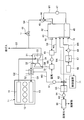
- FIG. 1 is a schematic configuration diagram illustrating an exhaust gas treatment apparatus according to the first embodiment.
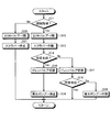
- FIG. 2 is a flowchart showing the flow of processing by the exhaust gas processing apparatus of the first embodiment.
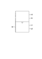
- FIG. 3 is a schematic diagram for statement of water supply control for the water storage section.
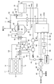
- FIG. 4 is a schematic configuration diagram illustrating the exhaust gas treatment apparatus of the second embodiment.
- FIG. 1 is a schematic configuration diagram showing an exhaust gas treatment apparatus of the first embodiment
- FIG. 2 is a flowchart showing a flow of treatment by the exhaust gas treatment apparatus of the first embodiment
- FIG. 3 is a statement of water supply control to the water storage unit. It is the schematic for doing.
- the exhaust gas treatment apparatus of the first embodiment mixes a part of the exhaust gas discharged from the marine diesel engine with air and then compresses it with a supercharger and recirculates it as a combustion gas mixture to the marine diesel engine, It removes harmful substances from the exhaust gas that circulates.
- a marine diesel engine 11 is a propulsion engine (main engine) that drives and rotates a propeller for propulsion via a propeller shaft, although not shown.
- This marine diesel engine 11 is a uniflow scavenging exhaust type diesel engine, which is a two-stroke diesel engine, in which the flow of intake and exhaust in the cylinder is unidirectional from the bottom to the top so as to eliminate residual exhaust.
- the diesel engine 11 includes a cylinder (combustion chamber) 12 in which a piston moves up and down, a scavenging chamber 13 communicating with the cylinder 12, and an exhaust port 14 communicating with the cylinder 12 and provided with an exhaust valve.
- the air supply line G ⁇ b> 1 is connected to the scavenging chamber 13, and the exhaust line G ⁇ b> 2 is connected to the exhaust port 14.
- the supercharger 21 is configured by connecting a compressor 22 and a turbine 23 so as to rotate integrally with a rotary shaft 24.
- the turbine 23 is rotated by the exhaust gas discharged from the exhaust line G ⁇ b> 2 of the diesel engine 11, and the rotation of the turbine 23 is transmitted by the rotary shaft 24 to rotate the compressor 22.
- the recirculated gas is compressed and supplied to the diesel engine 11 from the supply line G1.
- the turbocharger 21 is connected to an exhaust line G3 that discharges exhaust gas that has rotated the turbine 23.
- the exhaust line G3 is connected to a chimney (funnel) (not shown).
- the exhaust gas recirculation line G4 branches off from the exhaust line G3.
- the exhaust gas recirculation line G4 is provided with an EGR valve (flow rate control valve) 41 and connected to a scrubber (a scrubber capable of removing SOx and dust).
- the EGR valve 41 adjusts the flow rate of the exhaust gas that passes through the exhaust gas recirculation line G4.
- the scrubber 42 removes harmful substances such as SOx and soot contained by injecting water into the exhaust gas.
- a Venturi type scrubber is adopted, but it is not limited to this configuration.
- the scrubber 42 has a hollow main body 43, a venturi section 44 into which exhaust gas is introduced, and a water storage section (water storage tank) 45 for storing waste water.
- the scrubber 42 has a water injection unit 46 that injects water to the exhaust gas introduced into the venturi unit 44, and a drain circulation line W ⁇ b> 1 for circulating the drainage of the water storage unit 45 to the water injection unit 46 is provided.
- a pump 47 is provided in the drainage circulation line W1.
- the scrubber 42 is provided with a gas discharge part 48 for discharging exhaust gas from which harmful substances have been removed, and is connected to a gas discharge line G5.
- the gas discharge line G ⁇ b> 5 is provided with a mist separator (mist eliminator) 49 and a blower (blower) 50, and is connected to a mixer (mixer) 51.
- the blower 50 discharges the exhaust gas in the scrubber 42 from the gas discharge part 48 to the gas discharge line G5.
- the mist separator 49 separates droplets of small-diameter particles contained in the exhaust gas from which harmful substances have been removed by water jet, and the separated separated water is returned to the water storage section 45 of the scrubber 42 by the separated water line W2. It is.
- the mixer (mixer) 51 mixes the air sucked from outside air and the exhaust gas (recirculation gas) from the gas discharge line G5 to generate a combustion mixed gas, and the combustion mixed gas is supercharged.
- a combustion air supply line G6 for supplying to the 21 compressors 22 is provided.
- the supercharger 21 can supply the combustion mixed gas compressed by the compressor 22 from the supply air line G1 to the diesel engine 11.
- the air supply line G1 is provided with an air cooler (cooler) 52.
- the air cooler 52 cools the combustion mixed gas compressed by the compressor 22 to a high temperature by exchanging heat with cooling water.
- the air cooler 52 cools the high-temperature combustion mixed gas, so that the temperature and pressure are reduced, so that the water vapor contained is condensed and condensed water (drain water) is generated.
- the air cooler 52 is provided with a drain water discharge line W3 for discharging the generated drain water, and a drain water pump 61 is provided in the drain water discharge line W3.
- the drain water discharge line W3 is connected to a drain water supply line (condensed water supply line) W4 and a drain water treatment line W5 via a drain valve 62.
- the drain water supply line W4 is connected to the scrubber 42. Further, the drain water treatment line W5 is provided with a drain water tank 63 and a pump 64, and is connected to the treatment device 65.
- the treatment device 65 removes oil such as lubricating oil and system oil of the diesel engine 11 from the drain water, drains the treated water as it is, and stores the separated waste in a waste container (not shown).
- the ship is equipped with a fresh water generator 66 for producing fresh water, and a fresh water tank 67 for storing fresh water produced by the fresh water generator 66 is connected. And the fresh water tank 67 is connected with the scrubber 42 by the fresh water supply line W6, and the fresh water pump 68 is provided in the fresh water supply line W6.
- the control device 71 can control the EGR valve 41, the drain valve 62, and the fresh water pump 68.
- the control device 71 controls the opening and closing of the EGR valve 41 according to the operational state (operating sea area) of the ship. That is, the control device 71 closes the EGR valve 41 if the current operating area of the ship is not a NOx restricted area that restricts NOx emission, and opens the EGR valve 41 if it is a NOx restricted area.
- the control device 71 controls the drain valve 62 and the fresh water pump 68 according to the amount of drainage water in the scrubber 42. That is, since the scrubber 42 removes harmful substances by performing water injection on the exhaust gas, a part of the injection water becomes steam due to the high-temperature exhaust gas and is carried away by the exhaust gas. Further, although not shown, the scrubber 42 cleans the drainage of the water storage unit 45 with a filter, so that part of the drainage is carried away together with the waste. Therefore, the scrubber 42 needs to replenish water for jetting periodically.
- the scrubber 42 is provided with a water amount sensor 72 that measures the amount of waste water stored in the water storage unit 45.
- the control device 71 switches the drain valve 62 when the water amount of the water storage unit 45 measured by the water amount sensor 72 is less than a preset lower limit value, thereby draining water drained from the air cooler 52 to the drain water discharge line W3. Is supplied to the water storage part 45 of the scrubber 42 through the drain water supply line W4.
- the control device 71 is discharged from the air cooler 52 to the drain water discharge line W3 by switching the drain valve 62 when the amount of water in the water storage section 45 measured by the water amount sensor 72 is larger than a preset upper limit value.
- the drain water is supplied to the drain water tank 63 (treatment device 65) through the drain water treatment line W5.
- control device 71 switches the drain valve 62 and supplies the drain water to the water storage section 45 of the scrubber 42 through the drain water supply line W4. If the measured water volume of the water storage section 45 does not increase, the fresh water pump 68 Is operated to supply the fresh water stored in the fresh water tank 67 to the water storage section 45 of the scrubber 42 through the fresh water supply line W6. Thereafter, when the amount of water in the water storage unit 45 measured by the water amount sensor 72 exceeds the upper limit value, the control device 71 stops the operation of the fresh water pump 68, thereby supplying the water storage unit 45 of the scrubber 42 to the water storage unit 45 by the fresh water supply line W6. Stop supplying fresh water. At this time, by switching the drain valve 62, the drain water supply to the water storage unit 45 by the drain water supply line W4 is also stopped.
- the condensed water supply apparatus of this invention is comprised by the drain water discharge line W3, the drain water pump 61, the drain valve 62, the drain water supply line W4, etc.
- the fresh water supply apparatus of this invention is comprised by the fresh water supply line W6 and the fresh water pump 68.
- the EGR valve 41 when the EGR valve 41 is open, a part of the exhaust gas flows from the exhaust line G3 to the exhaust gas recirculation line G4.
- the scrubber 42 removes harmful substances such as NOx and soot contained in the exhaust gas flowing into the exhaust gas recirculation line G4. That is, in the scrubber 42, when the exhaust gas passes through the venturi unit 44 at a high speed, the water is injected from the water injection unit 46 to be cooled by the water, and fine particles (PM) such as SOx and dust. Falls with water and is removed. And the water containing SOx, dust, etc. is stored in the water storage part 45, and is returned to the water injection part 46 again by the pump 47 through the waste water circulation line W1.
- PM fine particles
- the exhaust gas from which harmful substances have been removed by the scrubber 42 is discharged from the gas discharge unit 48 to the gas discharge line G5, and after the droplets of small diameter particles are separated by the mist separator 49, the exhaust gas is mixed with the air sucked by the mixer 51 And becomes a mixed gas for combustion.
- the combustion mixed gas passes through the combustion air supply line G6, is compressed by the compressor 22 of the supercharger 21, is cooled by the air cooler 52, and is supplied to the diesel engine 11 from the air supply line G1.
- the air cooler 52 cools the high-temperature combustion mixed gas, thereby condensing water vapor and generating drain water, and this drain water is discharged to the drain water discharge line W3. Since this drain water contains oil, it normally flows from the drain water discharge line W3 to the drain water treatment line W5 and accumulates in the drain water tank 63, and the processing device 65 purifies the drain water.
- the control device 71 controls the drain valve 62 and the fresh water pump 68 according to the amount of drainage in the scrubber 42.
- control of the amount of stored water in the scrubber 42 by the control device 71 will be described in detail using a flowchart.
- step S11 it is determined whether or not the ship is navigating the NOx restricted area.
- the EGR valve 41 is opened in step S12, and the scrubber 42 is operated in step S13.
- the EGR valve 41 is closed in step S20, and the scrubber 42 is stopped in step S21.
- step S14 it is determined whether or not the water amount of the water storage unit 45 in the scrubber 42 measured by the water amount sensor 72 is at a predetermined water level (more than a lower limit value).
- the drain water discharge line W3 and the drain water treatment line W5 are moved by the drain valve 62 in step S15.
- the fresh water pump 67 is stopped in step S16.
- the drain water discharge line W3 and the drain water supply line W4 are moved by the drain valve 62 in step S17. Communicate.
- the drain valve 62 is switched so that the drain water discharge line W3 and the drain water supply line W4 communicate with each other, so that the drain water discharged from the air cooler 52 to the drain water discharge line W3 passes through the drain water supply line W4. It is supplied to the water reservoir 45. Therefore, the amount of water in the water storage unit 45 increases.
- step S18 it is determined again whether or not the water amount of the water storage section 45 in the scrubber 42 measured by the water amount sensor 72 is at a predetermined water level (more than the lower limit value). That is, even if the drain water from the air cooler 52 is supplied from the drain water supply line W4 to the water storage unit 45, the amount of water in the water storage unit 45 does not increase when the water consumption in the scrubber 42 is large. Therefore, if it is determined (Yes) that the amount of water in the water storage section 45 in the club 42 is at a predetermined water level (more than the lower limit value), this process is terminated.
- the fresh water pump 68 is operated in step S19. Then, the fresh water stored in the fresh water tank 67 by the fresh water pump 68 is supplied to the water storage part 45 of the scrubber 42 through the fresh water supply line W6. Therefore, the amount of water in the water storage unit 45 increases.
- step S14 After that, if it is determined in step S14 that the amount of water in the water storage section 45 is increased and is at the predetermined water level (Yes), the drain water discharge line W3 and the drain water treatment line W5 are communicated by the drain valve 62 in step S15. In step S16, the fresh water pump 67 is stopped. If it is determined in step S11 that the ship has deviated from the NOx restricted sea area (No), the EGR valve 41 is closed in step S20, and the scrubber 42 is stopped in step S21.
- an upper limit value and a lower limit value for the water amount of the water storage unit 45 are set, and the control device 71 switches the drain valve 62 when the water amount of the water storage unit 45 measured by the water amount sensor 72 exceeds the upper limit value. Or the operation of the fresh water pump 68 is stopped.
- upper limit values H1 and H2 and lower limit values L1 and L2 are set for the water level of the water storage section 45.
- the upper limit value H1 ⁇ H2, the lower limit value L1 ⁇ L2, and the water level is H2> H1> L1> L2.
- the initial water level of the water storage section 45 is between the lower limit value L1 and the upper limit value H1, the supply of drain water or still water is stopped.
- the supply of drain water is started when the water level falls below the lower limit L1 (L1 to L2). If the amount of drain water supplied is greater than the amount carried away, the supply of drain water is stopped at the time (H1 to H2) when the water level rises and reaches the upper limit value H2. On the other hand, if the drain water supply amount is less than the carry-off amount, the supply of fresh water is started at the time (L1 to L2) when the water level decreases and reaches the lower limit L2. When the water level rises and reaches the upper limit value H1, the supply of drain water is stopped at the time (L1 to H1).
- the amount taken away and the amount of drain water also change. At this time, since it cannot be determined that the amount taken away> drain water, drain water is supplied.
- the drain water supply amount is larger than the carry-away amount, the drain water supply is stopped when the water level rises to the upper limit value H2.
- the amount of drain water supplied is less than the amount taken away, the water level decreases.
- a part of the exhaust gas discharged from the marine diesel engine 11 is mixed with air and compressed by the supercharger 21 as a mixed gas for marine diesel engine.
- the exhaust gas recirculation line G4 that recirculates to the exhaust gas 11, the scrubber 42 that removes harmful substances by injecting water into the exhaust gas flowing through the exhaust gas recirculation line G4, and the compressor 22 after the harmful substances are removed by the scrubber 42
- An air cooler 52 that cools the combustion gas mixture compressed by the air cooler 52 and a drain water supply line W4 that supplies drain water generated by cooling the combustion gas mixture by the air cooler 52 to the scrubber 42 are provided.
- a part of the exhaust gas discharged from the marine diesel engine 11 passes through the exhaust gas recirculation line G4, is compressed by the supercharger 21, and is recirculated to the marine diesel engine 11 as a mixed gas for combustion.
- the scrubber 42 removes harmful substances by injecting water to the exhaust gas flowing through the exhaust gas recirculation line G4. Further, the air cooler 52 cools the combustion mixed gas compressed by the compressor 22 after the harmful substances are removed. At this time, since the air cooler 52 cools the combustion mixed gas, drain water is generated, and this drain water is supplied to the scrubber 42 through the drain water supply line W4. Therefore, the scrubber 42 can reduce the water shortage by supplying drain water, and can suppress the increase in size and cost of the apparatus by effectively using the treated water.
- a water storage unit 45 that stores water injected to the exhaust gas by the scrubber 42
- a water amount sensor 72 that measures the water amount of the water storage unit 45 and the water amount sensor 72 measure the water amount.
- a control device 71 is provided to supply drain water from the drain water supply line W4 to the water storage unit 45 by switching the drain valve 62 when the amount of water in the water storage unit 45 becomes smaller than a preset lower limit value. Therefore, the amount of water in the water storage section 45 in the scrubber 42 can be always maintained at an appropriate amount.
- a fresh water supply line W6 for supplying fresh water to the scrubber 42 and a fresh water pump 68 are provided, and the control device 71 supplies drain water from the drain water supply line W4 to the water storage unit 45.
- the fresh water pump 68 is operated to supply fresh water from the fresh water supply line W6 to the water storage section 45. Therefore, even if the amount of drain water is insufficient, the amount of water in the water storage section 45 in the scrubber 42 can be always maintained at an appropriate level by using fresh water.
- FIG. 4 is a schematic configuration diagram illustrating the exhaust gas treatment apparatus of the second embodiment.
- symbol is attached
- the marine diesel engine 11 has an air supply line G1 connected to the scavenging chamber 13 and an exhaust line G2 connected to the exhaust port 14.
- the supercharger 21 includes a compressor 22 and a turbine 23, and an exhaust line G ⁇ b> 3 is connected to the turbine 23.
- the exhaust line G3 is provided with an economizer (a economizer) 80, and is connected to a first scrubber (SOx removal scrubber) 81.
- the first scrubber 81 removes harmful substances such as SOx and dust contained by injecting water to the exhaust gas.
- the first scrubber 81 has a hollow main body 82, an introduction part 83 into which exhaust gas is introduced, and a water storage part 84 for storing waste water.
- the first scrubber 81 has a water injection unit 85 and a plurality of injection nozzles 86 that inject water into the exhaust gas introduced into the main body 82.
- the first scrubber 42 is provided with a gas discharge part 48 for discharging the exhaust gas from which harmful substances have been removed, and is connected to a gas discharge line G5.
- the exhaust line G3 has a downstream side of the first scrubber 81 connected to a chimney (funnel) (not shown). Further, the exhaust gas recirculation line G4 branches off from the exhaust line G3.
- the exhaust gas recirculation line G4 is provided with an EGR valve 41, to which a second scrubber (dust removal scrubber) 42 is connected.
- the 2nd scrubber 42 removes harmful substances, such as SOx and dust which contain, by injecting water with respect to waste gas.
- the second scrubber 42 has a main body 43, a venturi part 44, a water storage part 45, and a water injection part 46.
- a gas discharge line G ⁇ b> 5 is connected to a gas discharge unit 48, and this gas discharge line G ⁇ b> 5 is provided with a mist separator 49 and a blower 50 and is connected to a mixer 51.
- the mixer 51 mixes air sucked from outside air and exhaust gas (recirculation gas) to generate a combustion mixed gas, and is connected to the compressor 22 by a combustion air supply line G6.
- the compressor 22 can supply compressed combustion air from the supply air line G1 to the diesel engine 11.
- the air supply line G1 is provided with an air cooler (cooler) 52.
- the air cooler 52 cools the combustion mixed gas compressed by the compressor 22 to a high temperature by exchanging heat with cooling water.
- the water storage tank 91 stores the waste water from the first and second scrubbers 81 and 42. That is, the first scrubber 81 is connected to a drain line W11 for discharging the drainage of the water storage section 84, and the second scrubber 42 is connected to a drainage line W12 for discharging the drainage of the water storage section 45.
- the drain lines W11 and W12 are collected by a drain line W13, and the drain line W13 is connected to a water storage tank 91.
- the drainage of the water storage part 84 of the first scrubber 81 is discharged to the drainage line W11
- the drainage of the water storage part 45 of the second scrubber 42 is discharged to the drainage line W12
- the drainage of each drainage line W11, W12 is It is discharged and stored in the water storage tank 91 by the drain line W13.
- the 1st scrubber 81 is provided with the drainage circulation line W14 which circulates the waste_water
- the second scrubber 42 is provided with a drainage circulation line W1 for circulating the drainage of the water storage tank 91 to the water injection unit 46, and a pump 47 is provided in the drainage circulation line W1.
- the above-described air cooler 52 cools the high-temperature combustion mixed gas, so that the temperature and pressure are reduced, so that the water vapor contained is condensed and condensed water (drain water) is generated.
- the air cooler 52 is provided with a drain water discharge line W3 for discharging the generated drain water, and a drain water pump 61 is provided in the drain water discharge line W3.
- the drain water discharge line W3 is connected to a drain water supply line W4 and a drain water treatment line W5 via a drain valve 62.
- the drain water supply line W4 is connected to the water storage tank 91. Further, the drain water treatment line W5 is provided with a drain water tank 63 and a blower 64, and is connected to the treatment device 65. Moreover, the ship is equipped with a fresh water generator 66 for producing fresh water, and a fresh water tank 67 for storing fresh water produced by the fresh water generator 66 is connected thereto. And the fresh water tank 67 is connected with the water storage tank 91 by the fresh water supply line W6, and the fresh water pump 68 is provided in the fresh water supply line W6.
- the control device 71 can control the drain valve 62 and the fresh water pump 68.
- the control device 71 controls the drain valve 62 and the fresh water pump 68 according to the amount of drainage in the water storage tank 91. That is, since each scrubber 81, 42 removes harmful substances by performing water injection on the exhaust gas, a part of the injection water becomes steam due to the high-temperature exhaust gas and is carried away by the exhaust gas. Moreover, although each scrubber 81 and 42 is not shown in figure, since the waste_water
- the water storage tank 91 is provided with a water amount sensor 72 that measures the amount of stored waste water.
- the control device 71 switches the drain valve 62 when the water amount in the water storage tank 91 measured by the water amount sensor 72 is smaller than a preset lower limit value, thereby draining water drained from the air cooler 52 to the drain water discharge line W3. Is supplied to the water storage part 45 of the second scrubber 42 through the drain water supply line W4.
- the control device 71 is discharged from the air cooler 52 to the drain water discharge line W3 by switching the drain valve 62 when the amount of water in the water storage tank 91 measured by the water amount sensor 72 exceeds a preset upper limit value.
- the drain water is supplied to the drain water tank 63 (treatment device 65) through the drain water treatment line W5.
- the control device 71 switches the drain valve 62 and supplies the drain water to the water storage tank 91 of the scrubber 42 through the drain water supply line W4. If the measured water amount of the water storage tank 91 does not increase, the fresh water pump 68 Is operated to supply the fresh water stored in the fresh water tank 67 to the water storage tank 91 through the fresh water supply line W6. Thereafter, when the amount of water in the water storage tank 91 measured by the water amount sensor 72 exceeds the upper limit value, the control device 71 stops the operation of the fresh water pump 68, thereby supplying fresh water to the water storage tank 91 by the fresh water supply line W6. To stop. At this time, by switching the drain valve 62, the drain water supply to the water storage tank 91 by the drain water supply line W4 is also stopped.
- the exhaust gas discharged from the marine diesel engine 11 is discharged to the exhaust line G3 after rotating the turbine 23 in the supercharger 21, and the EGR valve 41 is closed. The entire amount is discharged to the outside from the exhaust line G3.
- PM fine particles
- the drainage of the water storage portion 84 of the first scrubber 81 is discharged to the drainage line W11
- the drainage of the water storage portion 45 of the second scrubber 42 is discharged to the drainage line W12
- the drainage line W13 is discharged to the water storage tank 91 by the drainage line W13.
- the first scrubber 81 returns the water in the water storage tank 91 to the water injection unit 46 again through the drainage circulation line W1 by the pump 47
- the second scrubber 42 uses the pump 47 to return the water in the water storage tank 91 to the drainage circulation line. It returns to the water injection part 46 again through W1.
- the exhaust gas from which harmful substances have been removed by the second scrubber 42 is discharged to the gas discharge line G5, the water is separated by the mist separator 49, and then mixed with the air sucked by the mixer 51 to become combustion air. .
- the combustion air passes through the combustion air supply line G6, is compressed by the compressor 22 of the supercharger 21, is cooled by the air cooler 52, and is supplied to the diesel engine 11 from the air supply line G1.
- the air cooler 52 cools the high-temperature combustion mixed gas, thereby condensing water vapor and generating drain water, and this drain water is discharged to the drain water discharge line W3.
- the drain water flows from the drain water discharge line W3 to the drain water treatment line W5 and accumulates in the drain water tank 63, and the treatment device 65 purifies the drain water.
- the control device 71 controls the drain valve 62 and the fresh water pump 68 according to the amount of drainage in the water storage tank 91. That is, when the amount of water in the water storage tank 91 measured by the water amount sensor 72 is not at the predetermined water level (less than the lower limit value), the drain water discharge line W3 and the drain water supply line W4 are communicated by the drain valve 62. Then, the drain valve 62 is switched to connect the drain water discharge line W3 and the drain water supply line W4, so that the drain water discharged from the air cooler 52 to the drain water discharge line W3 passes through the drain water supply line W4. To be supplied. Therefore, the amount of water in the water storage tank 91 increases.
- the water amount of the water storage tank 91 does not increase when the amount of water consumed in each of the scrubbers 81 and 42 is large. Therefore, at this time, the fresh water pump 68 is operated. Then, the fresh water stored in the fresh water tank 67 by the fresh water pump 68 is supplied to the water storage tank 91 through the fresh water supply line W6. Therefore, the amount of water in the water storage unit 45 increases.
- the drain valve 62 is switched and the operation of the fresh water pump 68 is stopped to stop the supply of drain water and fresh water to the water storage tank 91.
- the first scrubber 81 that removes harmful substances such as SOx and soot and the second scrubber 42 that removes harmful substances such as soot are provided, and each water storage section 84, 45 are connected to the water storage tank 91 by drain lines W11, W12, W13, and the drain valve 62 is switched when the water amount in the water storage tank 91 measured by the water amount sensor 72 is less than a preset lower limit value. Water is supplied to the water storage tank 91 from the drain water supply line W4. Therefore, the amount of water in the water storage tank 91 can always be maintained at an appropriate amount. Further, by sharing the water storage tank 91 for storing the waste water of the first scrubber 81 for removing SOx and the second scrubber 42 for removing dust, the apparatus can be reduced in size and cost.
- the main engine as a marine diesel engine, it is applicable also to the diesel engine used as a generator.
- the drain water pump 61 is provided in the drain water discharge line W3. However, since the combustion air has a high pressure, the drain water pump 61 may be omitted.
- the water storage tanks 91 for storing the waste water of the first scrubber 81 for removing SOx and the second scrubber 42 for removing dust are shared, but they may be provided individually.
Landscapes
- Engineering & Computer Science (AREA)
- Chemical & Material Sciences (AREA)
- Combustion & Propulsion (AREA)
- Mechanical Engineering (AREA)
- General Engineering & Computer Science (AREA)
- Chemical Kinetics & Catalysis (AREA)
- Analytical Chemistry (AREA)
- Thermal Sciences (AREA)
- Physics & Mathematics (AREA)
- General Chemical & Material Sciences (AREA)
- Oil, Petroleum & Natural Gas (AREA)
- Ocean & Marine Engineering (AREA)
- Exhaust Gas After Treatment (AREA)
- Treating Waste Gases (AREA)
- Exhaust-Gas Circulating Devices (AREA)
- Gas Separation By Absorption (AREA)
- Separation Of Particles Using Liquids (AREA)
Abstract
Description
図1は、第1実施形態の排ガス処理装置を表す概略構成図、図2は、第1実施形態の排ガス処理装置による処理の流れを表すフローチャート、図3は、貯水部に対する水供給制御を声明するための概略図である。
図4は、第2実施形態の排ガス処理装置を表す概略構成図である。なお、上述した実施形態と同様の機能を有する部材には、同一の符号を付して詳細な説明は省略する。
21 過給機
41 EGRバルブ
42 スクラバ、第2スクラバ
45 貯水部(貯水タンク)
52 エアクーラ(冷却器)
62 ドレンバルブ(凝縮水供給装置)
66 造水機
67 清水タンク
68 清水ポンプ(清水供給装置)
71 制御装置
72 水量センサ
81 第1スクラバ
G4 排ガス再循環ライン
W3 ドレン水排出ライン(凝縮水供給装置)
W4 ドレン水供給ライン(凝縮水供給装置)
W6 清水供給ライン(清水供給装置)
W11,W12,W13 排水ライン
Claims (7)
- エンジンから排出された排ガスの一部を燃焼用混合ガスの一部として前記エンジンに再循環する排ガス再循環ラインと、
前記排ガス再循環ラインを流れる排ガスに対して水を噴射することで有害物質を除去するスクラバと、
空気と再循環ガスを混合した燃焼用混合ガスを冷却する冷却器と、
前記冷却器により燃焼用混合ガスを冷却することで発生した凝縮水を前記スクラバに供給する凝縮水供給装置と、
を有することを特徴とする排ガス処理装置。 - 排ガスに対して噴射された水を貯留する貯水タンクと、前記貯水タンクの水量を計測する水量センサと、前記水量センサが計測した前記貯水タンクの水量が予め設定された値を超えたら前記凝縮水供給装置から凝集水を供給する、あるいは供給を止める制御装置が設けられることを特徴とする請求項1に記載の排ガス処理装置。
- 清水を前記スクラバに供給する清水供給装置が設けられ、前記制御装置は、前記凝縮水供給装置を作動しても前記水量センサが計測した前記貯水タンクの水量が増加しないときは前記清水供給装置を作動させることを特徴とする請求項2に記載の排ガス処理装置。
- 前記スクラバは、排ガス中の煤塵を除去可能なスクラバまたは排ガス中のSOxを除去可能なスクラバであることを特徴とする請求項1から請求項3のいずれか一項に記載の排ガス処理装置。
- 前記スクラバは、排ガス中の煤塵を除去する煤塵除去用スクラバ及び排ガス中のSOxを除去するSOx除去用スクラバを有し、前記貯水タンクは、前記煤塵除去用スクラバ及び前記SOx除去用スクラバからの排水を貯留することを特徴とする請求項2または請求項3に記載の排ガス処理装置。
- 請求項1から請求項5のいずれか一項に記載の排ガス処理装置を備えることを特徴とする船舶。
- エンジンから排出される排ガスに噴射する水を供給する方法であって、
前記エンジンへ供給される燃焼用混合ガスを冷却することで得られる凝縮水を前記排ガスに噴射する水として供給することを特徴とする水供給方法。
Priority Applications (4)
| Application Number | Priority Date | Filing Date | Title |
|---|---|---|---|
| CN201580002752.4A CN105849375B (zh) | 2014-01-09 | 2015-01-05 | 排气处理装置、船舶、水供给方法 |
| KR1020167014068A KR101807446B1 (ko) | 2014-01-09 | 2015-01-05 | 배기 가스 처리 장치, 선박, 물 공급 방법 |
| EP15735315.2A EP3098406B1 (en) | 2014-01-09 | 2015-01-05 | Exhaust gas treatment device, ship, and water supply method |
| DK15735315.2T DK3098406T3 (en) | 2014-01-09 | 2015-01-05 | Flue gas treatment vessel, ship and water supply method |
Applications Claiming Priority (2)
| Application Number | Priority Date | Filing Date | Title |
|---|---|---|---|
| JP2014002756A JP5916772B2 (ja) | 2014-01-09 | 2014-01-09 | 排ガス処理装置、船舶、水供給方法 |
| JP2014-002756 | 2014-01-09 |
Publications (1)
| Publication Number | Publication Date |
|---|---|
| WO2015105073A1 true WO2015105073A1 (ja) | 2015-07-16 |
Family
ID=53523900
Family Applications (1)
| Application Number | Title | Priority Date | Filing Date |
|---|---|---|---|
| PCT/JP2015/050053 Ceased WO2015105073A1 (ja) | 2014-01-09 | 2015-01-05 | 排ガス処理装置、船舶、水供給方法 |
Country Status (6)
| Country | Link |
|---|---|
| EP (1) | EP3098406B1 (ja) |
| JP (1) | JP5916772B2 (ja) |
| KR (1) | KR101807446B1 (ja) |
| CN (1) | CN105849375B (ja) |
| DK (1) | DK3098406T3 (ja) |
| WO (1) | WO2015105073A1 (ja) |
Cited By (5)
| Publication number | Priority date | Publication date | Assignee | Title |
|---|---|---|---|---|
| CN108602002A (zh) * | 2016-02-10 | 2018-09-28 | 三菱重工业株式会社 | 除雾单元以及egr系统 |
| CN108892308A (zh) * | 2018-08-20 | 2018-11-27 | 苏州鑫泽雅节能设备有限公司 | 工业废气及废水、循环冷却水物化处理系统 |
| EP3348805A4 (en) * | 2015-09-10 | 2019-06-12 | Samsung Heavy Industries Co., Ltd. | DEVICE FOR EMISSION CONTROL |
| WO2021045199A1 (ja) * | 2019-09-06 | 2021-03-11 | 株式会社ジャパンエンジンコーポレーション | 排ガス処理装置および水供給方法 |
| WO2021045200A1 (ja) * | 2019-09-06 | 2021-03-11 | 株式会社ジャパンエンジンコーポレーション | 排ガス処理の水供給装置 |
Families Citing this family (16)
| Publication number | Priority date | Publication date | Assignee | Title |
|---|---|---|---|---|
| JP6147786B2 (ja) * | 2015-03-13 | 2017-06-14 | 三菱重工業株式会社 | 給水タンク、排ガス処理装置、船舶 |
| JP6109983B1 (ja) * | 2016-03-04 | 2017-04-05 | 三菱重工業株式会社 | Egrシステム |
| JP6486978B2 (ja) | 2017-02-10 | 2019-03-20 | 三菱重工業株式会社 | 積層部材、並びに、これを用いた羽根車、圧縮機及びエンジン |
| JP6781673B2 (ja) * | 2017-06-22 | 2020-11-04 | 株式会社神戸製鋼所 | 熱エネルギー回収装置 |
| WO2019016331A1 (de) | 2017-07-20 | 2019-01-24 | Tenneco Gmbh | Agr-system mit wasserkühlung |
| DE102017116346A1 (de) * | 2017-07-20 | 2019-01-24 | Tenneco Gmbh | AGR System mit Wasserkühlung |
| CN107795414B (zh) * | 2017-11-29 | 2020-07-28 | 哈尔滨工程大学 | 一种具有改进scr催化器结构的船用egr柴油机 |
| JP7127796B2 (ja) * | 2018-03-26 | 2022-08-30 | 国立研究開発法人 海上・港湾・航空技術研究所 | 排ガス規制に対応した運転を行なう船舶、及び船舶の排ガス規制に対応した運転方法 |
| JP7058565B2 (ja) * | 2018-06-26 | 2022-04-22 | 三菱化工機株式会社 | 固形成分分離装置の制御装置、固形成分分離装置、舶用排気ガススクラバーシステム、および舶用ディーゼルエンジン |
| KR102157962B1 (ko) * | 2019-05-03 | 2020-09-18 | 현대중공업 주식회사 | 휘발성 유기화합물 처리 시스템 및 선박 |
| JP7039790B2 (ja) * | 2019-08-02 | 2022-03-23 | 株式会社三井E&Sマシナリー | 排ガス処理装置およびその制御方法 |
| KR102345284B1 (ko) * | 2020-07-21 | 2022-01-03 | 대우조선해양 주식회사 | 선박의 egr 결합 온실가스 배출 저감장치 및 동 장치를 구비한 선박 |
| KR102231476B1 (ko) * | 2020-12-10 | 2021-03-25 | 대우조선해양 주식회사 | 선박의 EGR 및 iCER 결합 온실가스 배출 저감장치 및 동 장치를 구비한 선박 |
| SE546328C2 (en) * | 2022-09-19 | 2024-10-08 | Cetech Ab | An exhaust recirculation device for a 4-stroke compression ignition engine |
| IT202300025470A1 (it) * | 2023-11-29 | 2025-05-29 | Coind S R L | Impianto di trattamento di fumi per applicazioni navali e metodo di riduzione delle emissioni inquinanti di un'imbarcazione |
| CN118724167A (zh) * | 2024-06-21 | 2024-10-01 | 上海中船三井造船柴油机有限公司 | 一种船用柴油机污水的排放转换系统 |
Citations (6)
| Publication number | Priority date | Publication date | Assignee | Title |
|---|---|---|---|---|
| JPH04139302A (ja) | 1990-10-01 | 1992-05-13 | Toshiba Corp | 発電プラントの復水・給水系ドレン水処理装置 |
| JP2011157959A (ja) * | 2010-01-29 | 2011-08-18 | Man Diesel & Turbo Filial Af Man Diesel & Turbo Se Tyskland | 排ガス再循環システムを備える大型2サイクルディーゼル機関 |
| JP2012127205A (ja) | 2010-12-13 | 2012-07-05 | Mitsubishi Heavy Ind Ltd | 排ガス再循環システム |
| JP2012180814A (ja) * | 2011-03-03 | 2012-09-20 | Mitsubishi Heavy Ind Ltd | 排ガス処理装置およびこれを備えた内燃機関 |
| JP2014005805A (ja) * | 2012-06-26 | 2014-01-16 | Mitsubishi Motors Corp | 内燃機関の排気浄化装置 |
| WO2014103337A1 (ja) * | 2012-12-28 | 2014-07-03 | 川崎重工業株式会社 | Egrユニット及び舶用エンジンシステム |
Family Cites Families (4)
| Publication number | Priority date | Publication date | Assignee | Title |
|---|---|---|---|---|
| DE102006054227A1 (de) * | 2006-11-15 | 2008-05-21 | Behr Gmbh & Co. Kg | Verfahren zur Verringerung des Schadstoffausstoßes einer Brennkraftmaschine, Vorrichtung zur Durchführung des Verfahrens und Abgasrückführsystem |
| JP2011157960A (ja) * | 2010-01-29 | 2011-08-18 | Man Diesel & Turbo Filial Af Man Diesel & Turbo Se Tyskland | 排ガス再循環制御システムを備える大型2サイクルディーゼル機関 |
| DK201000077U4 (da) * | 2010-04-29 | 2012-05-25 | Beco Consult Aps | Lukkemekanisme for kasser og låg |
| DE102012209286A1 (de) * | 2012-06-01 | 2013-12-05 | Man Diesel & Turbo Se | Brennkraftmaschine mit Abgasaufladung und Abgasrückführung |
-
2014
- 2014-01-09 JP JP2014002756A patent/JP5916772B2/ja active Active
-
2015
- 2015-01-05 DK DK15735315.2T patent/DK3098406T3/en active
- 2015-01-05 EP EP15735315.2A patent/EP3098406B1/en active Active
- 2015-01-05 CN CN201580002752.4A patent/CN105849375B/zh active Active
- 2015-01-05 WO PCT/JP2015/050053 patent/WO2015105073A1/ja not_active Ceased
- 2015-01-05 KR KR1020167014068A patent/KR101807446B1/ko active Active
Patent Citations (6)
| Publication number | Priority date | Publication date | Assignee | Title |
|---|---|---|---|---|
| JPH04139302A (ja) | 1990-10-01 | 1992-05-13 | Toshiba Corp | 発電プラントの復水・給水系ドレン水処理装置 |
| JP2011157959A (ja) * | 2010-01-29 | 2011-08-18 | Man Diesel & Turbo Filial Af Man Diesel & Turbo Se Tyskland | 排ガス再循環システムを備える大型2サイクルディーゼル機関 |
| JP2012127205A (ja) | 2010-12-13 | 2012-07-05 | Mitsubishi Heavy Ind Ltd | 排ガス再循環システム |
| JP2012180814A (ja) * | 2011-03-03 | 2012-09-20 | Mitsubishi Heavy Ind Ltd | 排ガス処理装置およびこれを備えた内燃機関 |
| JP2014005805A (ja) * | 2012-06-26 | 2014-01-16 | Mitsubishi Motors Corp | 内燃機関の排気浄化装置 |
| WO2014103337A1 (ja) * | 2012-12-28 | 2014-07-03 | 川崎重工業株式会社 | Egrユニット及び舶用エンジンシステム |
Cited By (11)
| Publication number | Priority date | Publication date | Assignee | Title |
|---|---|---|---|---|
| EP3348805A4 (en) * | 2015-09-10 | 2019-06-12 | Samsung Heavy Industries Co., Ltd. | DEVICE FOR EMISSION CONTROL |
| CN108602002A (zh) * | 2016-02-10 | 2018-09-28 | 三菱重工业株式会社 | 除雾单元以及egr系统 |
| CN108892308A (zh) * | 2018-08-20 | 2018-11-27 | 苏州鑫泽雅节能设备有限公司 | 工业废气及废水、循环冷却水物化处理系统 |
| WO2021045199A1 (ja) * | 2019-09-06 | 2021-03-11 | 株式会社ジャパンエンジンコーポレーション | 排ガス処理装置および水供給方法 |
| WO2021045200A1 (ja) * | 2019-09-06 | 2021-03-11 | 株式会社ジャパンエンジンコーポレーション | 排ガス処理の水供給装置 |
| JP2021042682A (ja) * | 2019-09-06 | 2021-03-18 | 株式会社ジャパンエンジンコーポレーション | 排ガス処理の水供給装置 |
| JP2021042681A (ja) * | 2019-09-06 | 2021-03-18 | 株式会社ジャパンエンジンコーポレーション | 排ガス処理装置および水供給方法 |
| KR20220038135A (ko) * | 2019-09-06 | 2022-03-25 | 가부시키가이샤 자판엔진코포레숀 | 배기 가스 처리의 물 공급 장치 |
| KR20220038472A (ko) * | 2019-09-06 | 2022-03-28 | 가부시키가이샤 자판엔진코포레숀 | 배기 가스 처리 장치 및 물 공급 방법 |
| KR102639342B1 (ko) | 2019-09-06 | 2024-02-21 | 가부시키가이샤 자판엔진코포레숀 | 배기 가스 처리 장치 및 물 공급 방법 |
| KR102657658B1 (ko) | 2019-09-06 | 2024-04-15 | 가부시키가이샤 자판엔진코포레숀 | 배기 가스 처리의 물 공급 장치 |
Also Published As
| Publication number | Publication date |
|---|---|
| JP2015132179A (ja) | 2015-07-23 |
| CN105849375B (zh) | 2018-07-27 |
| DK3098406T3 (en) | 2019-03-04 |
| EP3098406A1 (en) | 2016-11-30 |
| EP3098406B1 (en) | 2019-01-02 |
| EP3098406A4 (en) | 2017-07-05 |
| JP5916772B2 (ja) | 2016-05-11 |
| KR20160078434A (ko) | 2016-07-04 |
| KR101807446B1 (ko) | 2017-12-08 |
| CN105849375A (zh) | 2016-08-10 |
Similar Documents
| Publication | Publication Date | Title |
|---|---|---|
| JP5916772B2 (ja) | 排ガス処理装置、船舶、水供給方法 | |
| JP6188033B2 (ja) | スクラバ、排ガス処理装置、船舶 | |
| JP6147786B2 (ja) | 給水タンク、排ガス処理装置、船舶 | |
| KR101784883B1 (ko) | 세정 냉각 장치, egr 유닛 및 엔진 시스템 | |
| KR102231469B1 (ko) | 선박의 egr 결합 온실가스 배출 저감장치 및 동 장치를 구비한 선박 | |
| JP3233749U (ja) | 排気ガス再循環のためのシステム、エンジン、及びディーゼル排気組成 | |
| JP6280328B2 (ja) | Egrユニット及びエンジンシステム | |
| WO2002068809A1 (fr) | Moteur de recirculation de gaz d'echappement pourvu d'un laveur de gaz et systeme de recirculation de gaz d'echappement | |
| CN104358627A (zh) | 船舶柴油机NOx和SOx联合减排装置及控制方法 | |
| CN107429638A (zh) | Egr系统 | |
| KR102012141B1 (ko) | Egr 시스템 | |
| CN114341481B (zh) | 废气处理装置和水供给方法 | |
| CN115768971B (zh) | 船舶的egr结合温室气体减排装置及具备该装置的船舶 | |
| KR20190067905A (ko) | 내연 기관 | |
| KR20210036180A (ko) | 선박 내 유증기 통합 처리 시스템 |
Legal Events
| Date | Code | Title | Description |
|---|---|---|---|
| 121 | Ep: the epo has been informed by wipo that ep was designated in this application |
Ref document number: 15735315 Country of ref document: EP Kind code of ref document: A1 |
|
| REEP | Request for entry into the european phase |
Ref document number: 2015735315 Country of ref document: EP |
|
| WWE | Wipo information: entry into national phase |
Ref document number: 2015735315 Country of ref document: EP |
|
| ENP | Entry into the national phase |
Ref document number: 20167014068 Country of ref document: KR Kind code of ref document: A |
|
| NENP | Non-entry into the national phase |
Ref country code: DE |