WO2015105182A1 - 粒子状物質検出素子、粒子状物質検出センサ並びに粒子状物質検出素子の製造方法 - Google Patents
粒子状物質検出素子、粒子状物質検出センサ並びに粒子状物質検出素子の製造方法 Download PDFInfo
- Publication number
- WO2015105182A1 WO2015105182A1 PCT/JP2015/050508 JP2015050508W WO2015105182A1 WO 2015105182 A1 WO2015105182 A1 WO 2015105182A1 JP 2015050508 W JP2015050508 W JP 2015050508W WO 2015105182 A1 WO2015105182 A1 WO 2015105182A1
- Authority
- WO
- WIPO (PCT)
- Prior art keywords
- particulate matter
- conductor layer
- conductor
- layer
- detection element
- Prior art date
- Legal status (The legal status is an assumption and is not a legal conclusion. Google has not performed a legal analysis and makes no representation as to the accuracy of the status listed.)
- Ceased
Links
Images










Classifications
-
- G—PHYSICS
- G01—MEASURING; TESTING
- G01N—INVESTIGATING OR ANALYSING MATERIALS BY DETERMINING THEIR CHEMICAL OR PHYSICAL PROPERTIES
- G01N15/00—Investigating characteristics of particles; Investigating permeability, pore-volume or surface-area of porous materials
- G01N15/06—Investigating concentration of particle suspensions
- G01N15/0656—Investigating concentration of particle suspensions using electric, e.g. electrostatic methods or magnetic methods
-
- G—PHYSICS
- G01—MEASURING; TESTING
- G01M—TESTING STATIC OR DYNAMIC BALANCE OF MACHINES OR STRUCTURES; TESTING OF STRUCTURES OR APPARATUS, NOT OTHERWISE PROVIDED FOR
- G01M15/00—Testing of engines
- G01M15/04—Testing internal-combustion engines
- G01M15/10—Testing internal-combustion engines by monitoring exhaust gases or combustion flame
- G01M15/102—Testing internal-combustion engines by monitoring exhaust gases or combustion flame by monitoring exhaust gases
-
- G—PHYSICS
- G01—MEASURING; TESTING
- G01N—INVESTIGATING OR ANALYSING MATERIALS BY DETERMINING THEIR CHEMICAL OR PHYSICAL PROPERTIES
- G01N15/00—Investigating characteristics of particles; Investigating permeability, pore-volume or surface-area of porous materials
- G01N15/06—Investigating concentration of particle suspensions
- G01N15/0606—Investigating concentration of particle suspensions by collecting particles on a support
-
- G—PHYSICS
- G01—MEASURING; TESTING
- G01N—INVESTIGATING OR ANALYSING MATERIALS BY DETERMINING THEIR CHEMICAL OR PHYSICAL PROPERTIES
- G01N15/00—Investigating characteristics of particles; Investigating permeability, pore-volume or surface-area of porous materials
- G01N2015/0042—Investigating dispersion of solids
- G01N2015/0046—Investigating dispersion of solids in gas, e.g. smoke
Definitions
- the present disclosure is preferably used in, for example, an exhaust purification system of an internal combustion engine for a vehicle, and a particulate matter detection element, a particulate matter detection sensor, and a particulate matter detection sensor that detect particulate matter present in an exhaust gas that is a gas to be measured.
- the present invention relates to a method for manufacturing a particulate matter detection element.
- particulate matter detection sensors for detecting particulate matter in various gases to be measured have been proposed.
- a particulate matter detection sensor is formed by forming a pair of electrodes on the surface of an insulating substrate and depositing the particulate matter between the pair of electrodes by utilizing the conductivity of the particulate matter.
- Particulate matter in a gas to be measured such as combustion exhaust gas of an internal combustion engine is detected from changes in electric characteristics such as a resistance value and capacitance.
- JP-T-2008-502892 discloses a sensor element in which a pair of comb-shaped electrodes are formed on an insulating substrate such as alumina ceramics.
- a voltage is applied between the pair of electrodes from the power supply unit to form a non-uniform electric field in the space between the interdigitated electrodes, and is included in the exhaust gas passing through the sensor element.
- the soot deposition amount can be measured by attracting soot particles to the electrode and depositing them, and detecting the interelectrode resistance at this time.
- conductor layers and insulating layers are alternately stacked to form a laminated structure, and the conductor layers exposed in the cross section are used as a pair of electrodes.
- charge concentration occurs at the corners of the electrode ends. For this reason, it has been found that local particulate matter is likely to be deposited near the electrode end portion where the electric field strength is high, and the individual difference of the insensitive mass may be increased, leading to a decrease in detection accuracy.
- the present disclosure is configured by stacking flat conductor layers and flat insulating layers alternately to form a laminated structure, and the detection unit is configured with the conductor layers exposed in the cross section as a pair of electrodes.
- a particulate matter detection element having a characteristic shape at the end of the electrode layer and suppressing electric field concentration at the end of the electrode layer is provided, and the particulate matter detection element is used.
- the gas to be measured is detected by detecting electric characteristics that change depending on the amount of particulate matter deposited between the electrodes while collecting an electric field by applying a high voltage between a pair of electrodes to form an electric field.
- a particulate matter detection sensor that detects particulate matter in the interior with high accuracy and a method for manufacturing a particulate matter detection element that can achieve high detection accuracy by suppressing the concentration of charges on the electrode end The purpose is to do.
- the particulate matter detection element (10, 10a, 10c, 10d, 10f) of the present disclosure includes a flat conductor layer (11, 11a, 11c, 11d, 11f, 12, 12a, 12c, 12d, 12f) and a flat plate shape. Insulating layers (100, 100a, 100c, 100c, 100d, 100f) are alternately stacked, and this cross section is used to form a detection unit (a pair of detection electrodes having different polarities). 13, 13a, 13c, 13d, 13f). And it is used in order to detect the particulate matter in the gas to be measured by measuring the electrical characteristics that change depending on the amount of the particulate matter deposited on the detector.
- the conductor layer has a constant thickness, and a conductor layer plane portion (110, 110a, 110c, 110d, 110f, 120, 120a, 120c, 120d, 120f) having a strip-shaped cross section.
- the conductor layer edge portions (111, 111a, 111c, 111d, 111f, 121, 121a, 121c, 121d, 121f) are tapered on both sides of the plane portion of the conductor layer.
- the conductor layer has a constant film thickness and has a strip-shaped conductor layer plane portion (110b, 110e, 110g, 120b, 120e, 120g) on both sides of the conductor layer plane portion. You may comprise the conductor layer edge part (111b, 111e, 111g, 121b, 121e, 121g) of the circular arc shape of a cross section which curves smoothly.
- FIG. 1A is an enlarged perspective view of a detection unit 13 that is a main part of the particulate matter detection element 10 used in the particulate matter detection sensor 1 of FIG. 1A.
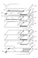
- FIG. 1A is a developed perspective view showing an example of the internal structure of the particulate matter detection element 10 used in the particulate matter detection sensor 1 of FIG. 1A.
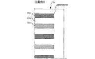
- the enlarged view of the principal part of the conventional particulate matter detection element 10z whose electrode layer end surface shown as the comparative example 1 is square shape.
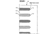
- the enlarged view of the principal part of the particulate-material detection element 10 whose electrode layer end surface shown as Example 1 of this indication is an obtuse triangle shape.
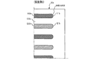
- the enlarged view of the principal part of the particulate-material detection element 10b whose electrode layer end surface shown as Example 3 of this indication is circular arc shape.
- An enlarged view of the main part of the particulate matter detection element 10e in which the end face of the electrode layer shown as Example 6 of the present disclosure has an arc shape and the position of the end face is The schematic diagram which shows the electric field strength distribution of the detection part plane in the comparative example 1
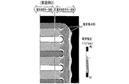
- the schematic diagram which shows the electric field strength distribution of the detection part plane in Example 1 The schematic diagram which shows the electric field strength distribution of the detection part plane in Example 2
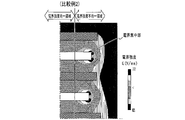
- the schematic diagram which shows the electric field strength distribution of the detection part plane in Example 3 Schematic diagram showing the electric field intensity distribution on the detection unit plane in Comparative Example 2
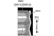
- the schematic diagram which shows the electric field strength distribution of the detection part plane in Example 4 The schematic diagram which shows the electric field strength distribution of the detection part plane in Example 5
- the schematic diagram which shows the electric field strength distribution of the detection part plane in Example 6 The principal part expansion perspective view which shows the outline
- FIG. The characteristic view which shows the change of the sensor output of Example 1 with Comparative Example 1
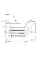
- summary of the manufacturing process of Example 1 of this indication The schematic diagram which shows the outline
- summary of the screen for thick film printing used in manufacture of the particulate matter detection element of this indication 9A is a sectional view taken along the line BB and a sectional view and a plan view of an insulating layer formed with a corresponding conductor layer.
- the particulate matter detection sensor 1 (hereinafter referred to as sensor 1) of the present disclosure is, for example, a particulate form in which combustion exhaust from an internal combustion engine is a measurement gas and a detection unit 13 provided in the measurement gas is provided.
- the material detection element 10 (hereinafter, abbreviated as the element 10), the power source 2 that applies a predetermined voltage to the element 10, and the electrical characteristics such as the current flowing through the element 10, the change in voltage, and the change in impedance are measured.
- the measuring unit 3 detects particulate matter in the gas to be measured.
- the particulate matter in the gas it is possible to detect the particulate matter in the gas to be measured by measuring the electrical characteristics that change depending on the amount of the particulate matter deposited on the detection unit 13 of the element 10 by the measurement unit 3.
- the side where the detection unit 13 of the element 10 is provided and exposed to the gas to be measured is referred to as the distal end side
- the side connected to the power supply unit 2 and the measurement unit 3 is referred to as the proximal end side.
- the sensor 1 is installed downstream of a DPF (Diesel Particulate Filter) and can be used for detecting an abnormality of the DPF. Alternatively, it can be used in a system that is installed upstream of the DPF and directly detects the particulate matter PM flowing into the DPF. It should be noted that, when actually disposed in the gas flow path to be measured, a known publicly-used sensor that is generally used as a particulate matter detection sensor such as a housing (not shown) or a cover body that protects the detection unit 13 in order to fix the element 10. The configuration described above can be employed as appropriate.
- a DPF Diesel Particulate Filter
- the element 10 has a laminated structure in which flat conductor layers 11 and 12 and flat insulating layers 100 are alternately stacked.
- the element 10 constitutes a detection unit 13 using the cross sections of the conductor layers 11 and 12 as a pair of detection electrodes having different polarities.
- the detection unit 13 includes a pair of conductor layers 11 and 12 arranged alternately with the insulating layer 100 interposed therebetween.
- the conductor layers 11 and 12 have a constant film thickness, the conductor layer plane portions 110 and 120 (hereinafter, abbreviated as the plane portions 110 and 120) having a strip-like cross section, and the conductor layer plane.
- the conductor layer edge portions 111 and 121 (hereinafter, abbreviated as the edge portions 111 and 121) having a tapered cross section are provided.
- the electric field concentration at the edges of the conductor layers 11 and 12 is suppressed. It is intended to prevent local particulate matter from being deposited on the concentrated portion (that is, the portion where the electric field is concentrated), and to improve and stabilize detection accuracy.
- a known conductive material can be appropriately used.
- a metal material such as aluminum, gold, platinum, or tungsten, or a metal oxide material such as ruthenium oxide, or LNF (LaNi 0.6 Fe 0.4 O 3 ), LSN (LaNi 0.6 Fe 0.4 O 3 ), LSM (La 1-X Sr X MnO 3- ⁇ ), LSC (La 1-X Sr X CoO 3- ⁇ ), LCC (La 1-X Ca X CrO 3- ⁇ ), LSCN (La 0.85 Sr 0 Perovskite type conductive oxide material selected from any one of .15 Cr 1-X Ni X O 3- ⁇ ) (0.1 ⁇ X ⁇ 0.7) can be used.
- the insulating layer 100 includes an insulating layer material such as alumina, magnesia, titania, mullite, a dielectric material obtained by mixing a high dielectric constant material such as barium titanate having a high dielectric constant with alumina or zirconia, or 8YSZ (ZrO 2 ).
- a known ceramic material such as partially stabilized zirconia typified by 0.82 (Y 2 O 3 ) 0.08 ) can be used as appropriate.
- the example which formed the detection part 13 by exposing the cross section of a pair of conductor layers 11 and 12 to the side surface direction of the front end side of the particulate matter detection element 10 formed in the rectangular parallelepiped shape is shown.
- the detection unit 13 may be provided by exposing the cross section of the pair of conductor layers 11 and 12 from the bottom surface on the tip side of the element 10.
- FIGS. 1A to 1C different hatchings are applied to clarify that the pair of conductor layers 11 and 12 are alternately stacked and the polarities are alternately different. There is no distinction between materials.
- the insulating layer 100 is formed in a flat plate shape by a known manufacturing method such as a doctor blade method, and through holes are formed at predetermined positions as necessary to form through hole electrodes 114 and 124.
- the pair of conductor layers 11 and 12 are formed by plane portions 110 and 120 provided with end edge portions 111 and 121 by a manufacturing method described later, lead portions 112 and 122, terminal portions 113 and 123, and through-holes for connection to the outside.
- the electrodes 114, 124, and 125 are configured.
- the through-hole electrodes 114 and 124 are designed to conduct the flat portions 110 and 120 having the same polarity.
- the lead portions 112 and 122, the through-hole electrodes 114 and 124, and the terminal portions 113 and 123 are formed by a known manufacturing method such as thick film printing.
- a laminated structure is adopted. Specifically, it has a laminated structure in which a plurality of layers in which conductor layers 11 and 12 are alternately formed on the insulating layer 100 are stacked. In this embodiment, the lowermost insulating layer 100H generates heat by energization. A pair of lead portions 141 and a terminal portion 142 that make the heat generating body 140 and the heat generating body 140 conductive are formed to constitute the heat generating portion 14. A known resistance heating material such as tungsten, molybdenum silicite or ruthenium oxide is used for the heating element 140, and a known conductive metal material such as gold, platinum or tungsten is used for the lead portion 141 and the terminal portion 142. And formed by a known method such as thick film printing. The element 10 is integrated by firing. In addition, the detection unit 13 in the present embodiment is formed by performing a lamination and firing process, and then appropriately cutting and polishing so that a cross section is exposed on the side surface of the element 10.
- Example 2 Example 3, Comparative Example 2, Example 4, Example 5, and Example 6 will be described.
- the basic structure of both the comparative example and the example has the same laminated structure as that of the example 1 shown in FIG. 1C. 3 and 4 are distinguished by being assigned branch numbers z, y, x, and w, and Examples 2 to 8 are assigned branch numbers a to g, respectively.
- the insulating layers 100z, the conductor layers 110z, and the conductor layers 120z are alternately stacked.
- the conductor layers 110z and 120z of Comparative Example 1 have a rectangular cross section, a square end surface, and the end surfaces are aligned.
- the insulating layers 100, the conductor layers 110, and the conductor layers 120 are alternately stacked.
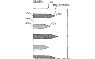
- the conductor layers 110 and 120 of the first embodiment are formed with edge portions 111 and 121 having a tapered (obtuse angle) cross section, and the positions of the edge portions 111 and 121 are aligned.
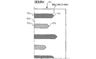
- the element 10a shown in FIG. 2C as Example 2 is different from Example 1 in that the edge portions 111a and 121a have an acute-angled triangular cross section.
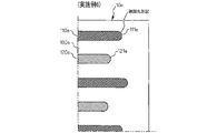
- the element 10b shown in FIG. 2D as Example 3 is different from Example 1 in that the edge portions 111b and 121b have an arc-shaped cross section.
- the conductor layer has a certain film thickness, the conductor layer plane portions 110b and 120b having a strip-like cross section, and the conductor layer edge portion 111b having a circularly curved cross section on both sides of the conductor layer plane portion. , 121b.
- the element 10y shown in FIG. 3A as Comparative Example 2 is different from the Comparative Example 1 in that the conductor layers 110y and 120y have square end faces, but the end face positions are not aligned.
- the conductive layers 110c and 120c are formed with the edge portions 111c and 121c having a tapered triangular (obtuse angle) cross section as in the first embodiment. The difference is that the positions of the edge portions 111c and 121c are not aligned.
- the conductive layers 110d and 120d are formed with the edge portions 111d and 121d having a tapered triangular (acute angle) cross section as in the second embodiment.
- the difference is that the positions of the edge portions 111d and 121d are not aligned.
- the element 10e shown in FIG. 3D as Example 6 has an arc-shaped cross section in which the edge portions 111e and 121e are curved as in Example 3, but the positions of the edge portions 111e and 121e are aligned. There is no difference.
- FIGS. 4A, 4B, 4C, 4D, 5A, 5B, 5C, and 5D it is generated on the plane of the detection unit when a certain voltage is applied between a pair of conductor layers. Differences in simulation results between Comparative Example 1, Examples 1 to 3, Comparative Example 2, and Examples 4 to 6 will be described with respect to the electric field intensity distribution.
- FIG. 4A in Comparative Example 1, a strong electric field concentration occurs at the corners of the conductor layers 11z and 12z, and the electric field strength in the region where the electric field strength between the pair of plane portions 110z and 120z is uniform is relatively high. Turned out to be lower. As shown in FIG.
- the electric field concentration portions are dispersed at the three portions of the edge portions 111 and 121, and the ratio of the electric field concentration becomes relatively low, and the flat portions 110 and 120 correspondingly. It was found that the charge intensity in the region where the electric field intensity becomes uniform becomes relatively high.
- Example 2 As shown in FIG. 4C, it was found that in Example 2, the electric field concentration was further suppressed, and the charge intensity in the region where the electric field intensity between the flat portions 110a and 120a became uniform was the highest. As shown in FIG. 4D, it has been found that in Example 3, the electric field concentration is suppressed and the electric charge intensity in the region where the electric field intensity between the flat portions 110b and 120b is uniform becomes relatively high.
- the element 10f according to the seventh embodiment of the present disclosure will be described.
- glass, alumina, or the like is used so as to cover a region where the electric field strength is nonuniform in all of the edge portions 111f and 121f and part of the flat portions 110f and 120f.
- a shielding layer 14 made of the same material as the known insulating material or the insulating layer 100 is provided.
- the configuration in which the shielding layer 14 is provided can be adopted in any of the first to sixth embodiments.
- Example 6 When a known amount of particulate matter was added to Comparative Example 4 provided with 14 and Example 8 provided with a shielding layer in Example 6, a plurality of samples were prepared for each of the Examples and Comparative Examples. The insensitive mass Q 0 until the gaseous substance was detected was measured.
- Comparative Example 1 the mean value ⁇ 2 of the dead mass Q 0 is small, and particulate matter can be detected at an early stage, but it has been found that the variation ⁇ 2 between samples is large.
- Example 1 the average value ⁇ 1 of the dead mass Q0 was larger than the dead mass of Comparative Example 1, but it was found that the variation ⁇ 1 between samples was much smaller.
- Comparative Example 1 a strong electric field concentration occurs at the corners of the end faces of the conductor layers 11z and 12z, and the particulate matter is attracted to the charges collected on the surfaces and deposited locally. Is presumed to be formed.
- end portions 111, 121, 111a, 121a, 111b, 121b, 111c, 121c, 111d, 121d, 111e, and 121e having a triangular or arcuate cross section on both end faces of the conductor layers 11 and 12, the electric field It is considered that concentration is suppressed and local deposition of particulate matter on the ends of the conductor layers 11 and 12 is suppressed.
- the edge portions 111a and 121a have an acute triangular shape in cross section, the distance between the vertices where electric field concentration is likely to occur is increased, so that a conduction path is formed between the pair of edge portions 111a and 121a. It is assumed that the time to complete will be longer.
- Comparative Example 1 shows a basic manufacturing method of the particulate matter detection element 10z in which the conductor layers 11z and 12z and the insulating layer 100z are alternately stacked and the cross section is used as the detection unit 13z.
- An insulating material such as alumina is mixed with a known binder, plasticizer, dispersant, solvent, etc. and stirred to form a slurry, which is formed into a sheet by a known manufacturing method such as a doctor blade method, and has an insulating property.
- a sheet 100zGS is obtained.
- a guide for printing alignment and through-hole electrodes 114z and 124z for connecting conductor layers having the same polarity are embedded in advance using a mold or the like.
- a through hole or the like for drilling is formed as necessary, and punched into a predetermined outer shape.
- the conductor paste is discharged from the thick film printing screen on which a predetermined conductor pattern is formed, and the conductor layer printed films 11zPRT and 12zPRT are transferred to the insulating layer sheet 100zGS.
- the film thickness near the center becomes thin and the film thickness near the outer periphery becomes thick due to the influence of the rheological characteristics and surface tension of the paste.
- a paste containing the same material as the insulating material constituting the insulating layer 100z is used to cover a portion other than the conductor layer with the same film thickness as the conductor layer printed films 11zPRT and 12zPRT by thick film printing.
- An intermediate layer 101z is formed.
- the insulating layer sheets 100zGS are stacked so that the polarities of the conductor layer printed films 11zPRT and 12zPRT are alternately switched, and are pressed using a mold or the like.
- the conductor layers 11z and 12z and the insulating layer 100z are fired at the same time to unite the laminated structure thus obtained. Thereafter, the element 10z is completed by exposing the cross-sections of the conductor layers 11z and 12z by cutting, polishing, or the like to form the detection unit 13z.
- Comparative Example 1 since the intermediate layer 101z is provided, the conductor layer printed films 11zPRT and 12zPRT and the conductor layer sheet 110z are hardly deformed at the time of laminating and pressing, and the mechanical strength of the element 10z is excellent. 11z and 12z maintain the shape of a strip-shaped cross section. However, it has been found that when a voltage is applied between the two conductor layers, the concentration of the electric field at the corners is large, and as described above, the variation in dead mass is large.
- the element 10y shown as the comparative example 2 is based on the manufacturing method similar to the comparative example 1, and is laminated by intentionally shifting the positions of the end surfaces of the conductor layers 11y and 12y in the lamination pressing process.
- Comparative Example 3 As shown in the printing process P1x, only the conductor layers 110x and 120x are printed on the insulating layer sheet 100xGS punched into a predetermined shape, and the process proceeds to the lamination pressing process P2x without providing an intermediate layer.
- the conductor layer printed films 11xPRT and 12xPRT are harder than the insulating layer sheet 100xGS. Therefore, at the time of laminated pressure bonding, the insulating layer sheet 100xGS is elastically deformed, and the conductor layer printed films 11xPRT and 12xPRT are changed to the insulating layer sheet 100xGS.
- the insulating layer sheets 100xGS are in close contact with each other so as to be recessed. At this time, voids having a triangular cross-section are formed on both sides of the conductor layer printed films 11xPRT and 12xPRT as shown in an enlarged manner in the circle of the lamination pressure bonding step P2x in FIG. 8B.
- Subsequent firing step P3x allows sintering to reduce the surface area of the voids, so the voids are reduced, but they do not disappear completely, but remain as voids or trigger delamination. There is a fear. Further, the end faces of the conductor layers 11x and 12x after firing have polygonal or irregular shapes, and electric field concentration is likely to occur at the corners as in Comparative Example 2 described above.
- Example 1 of the present disclosure With reference to FIG. 8C, an outline of the manufacturing process of Example 1 of the present disclosure will be described.
- a punching process in which a guide for positioning and a through hole as necessary are formed in the formed insulating layer sheet 100GS by a process similar to that of Comparative Example 1, and punched into a predetermined outer shape.
- a concave sheet 100PCD provided with a concave portion 101 that matches the shape of the predetermined conductor layer edge portions 111 and 121 in accordance with the positions where the conductor layers 110 and 120 are printed and formed.
- a protrusion for forming the recess 101 is provided on the punching die, and the surface of the insulating layer sheet 100GS is pressed. Thereby, the taper surface which inclines at a desired angle in the part which forms the conductor layer edge parts 111 and 121 can be formed.
- the insulating layer sheets 100GS can be easily brought into close contact with each other without providing an intermediate layer as used in Comparative Example 1.
- the conductor layers 11 and 12 and the insulating layer 100 are integrated by the firing step P3, the element 10 that hardly causes delamination can be formed.
- the conductor layer edge portions 111 and 121 can be formed in a triangular shape having a tapered cross section, it is easy to realize the element 10 in which electric field concentration is suppressed.
- FIG. 8D an outline of the manufacturing process of the second embodiment of the present disclosure will be described.
- the conductor printing process P1a in the present embodiment when the conductor layers 11 and 12 are printed and formed on the insulating layer sheet 100 (GS), the mesh opening ratio is partially changed, and the thickness of the printed film is changed at a predetermined position.
- the difference from the above embodiment is that the aperture ratio partial change printing screens PPM and PPMA set to be thin are used.
- the aperture ratio partial change printing screens PPM and PPMA will be described later with reference to FIGS. 9A, 9B, and 10.
- the aperture ratio partial change printing screen PPM by using the aperture ratio partial change printing screen PPM, the amount of the conductive paste discharged from the portion where the opening efficiency is set low is suppressed, and the thickness of the conductive layer formed thereby is reduced. It is possible to form the conductor layer edge portions 111a and 121a having a triangular cross section which is tapered outward and has an acute inclined surface.
- the conductor layers 11a and 12a are insulated by pressure-bonding the insulating layer sheet 100GS formed with the conductor layers 11a and 12a having the conductor layer edge portions 111a and 121a having a triangular cross section using a stacked mold or the like.
- the insulating layers 100GS are in close contact with each other while sinking into the layer 100GS.
- the conductor layer edge portions 111a and 121a have a tapered triangular shape, a gap as shown in Comparative Example 2 is not formed.
- FIGS. 9A and 9B the characteristics of the aperture ratio partial lowering screen M used in the production of the particulate matter detection element 10 of the present disclosure and the conductor layers 11 and 12 formed when the screen is used.
- the shape will be described.
- the conductor layer edge portion 121 is a pattern obtained by horizontally inverting one of the patterns. Therefore, the other is omitted, and the common configurations are described by arranging the reference numerals as 110/120.
- a part of a thick film printing screen generally used for thick film printing is rolled and partially flattened to reduce the mesh thickness and reduce the mesh opening ratio.
- a drop screen M is used.
- the resist film R is formed in a predetermined printing pattern by applying an emulsion on a printing screen and exposing and curing a pattern in accordance with the shape of the conductor layer plane portions 110 and 120, as in general thick film printing. ing. As shown in FIGS. 9A and 9B, the thickness of the mask M2 in the cross-sectional direction of the portion where the conductor layer edge portions 111 and 121 are printed is thin and the line width in the plane direction is wide.
- the aperture ratios of the portions where the edges 111 and 121 are formed by printing are the aperture ratios of the mask M1 of the portion where the conductor layer plane portion 110 is formed, ie, the plane portion. Opening efficiency for formation P 111 and P 121 is lower. For this reason, as shown in FIG. 9B, when the conductor layer plane portions 110 and 120 are printed and formed, the amount of paste discharged from the mask M2 is reduced, and the film thickness of the conductor layer edge portions 111 and 121 is determined as follows. It becomes thinner than the film thickness of the flat portions 110 and 120.
- the aperture ratio partial lowering screen M in which a part of the thick film printing screen is pressurized to reduce the aperture ratio has been shown as an example.
- the edge portion opening ratio P is increased by increasing the weaving density of the weft and warp of the mask M2A for printing the conductor layer edge portions 111 and 121 as compared to the mask M1A for printing the conductor layer flat portions 110 and 120.
- 111 A / P 121 A is made lower than the plane portion forming aperture ratio P 110 A / P 120 A.
- a screen mesh whose aperture ratio is partially adjusted in advance is used.
- a resist R is formed so as to have a predetermined conductor pattern.
- the conductor paste amount discharged from the mask M2A is suppressed at the conductor layer edge portions 111 and 121, and the film thickness is thinner than the conductor layer plane portions 110 and 120. Can be formed. Further, by gradually increasing the weaving density toward the outside, the film thickness of the conductor layer edge portions 111 and 121 can be gradually decreased toward the outside, and the tapered cross-sectional triangle shape can be obtained. it can.
- the method in which the conductor layer edge portions 111 and 121 can be formed in a desired shape in each of the punching process P0 and the printing process P1 has been described, but it is also possible to combine them.
- compression-bonding process although the conductor layers 11 and 12 were dried, the case where lamination
- the conductor layer 11 conforms to the shape of the depression 10. , 12 are fluidly deformed, so that the conductor layer edge portions 111, 121 can be formed in a desired shape.
- middle layer 101 which consists of an insulating material as shown in the comparative example 1 was shown in the lamination
- the intermediate layer 101 is printed by using a paste made of an insulating material in the printing process. Also good.
- the intermediate layer 101 By using the intermediate layer 101, the shear stress acting on the insulating layer sheet 100 at the time of laminate pressure bonding can be relaxed, the mechanical strength of the element 10 can be improved, and the occurrence of cracks at the time of firing can be suppressed. In addition to the improvement in detection accuracy, the effect of improving the durability of the element 10 can be expected.
- Particulate matter detection sensor 10 Particulate matter detection element 100 Insulating layer 11,12 Conductor layer 110,120 Conductor layer plane part 111,121 Conductor layer edge part 13 Detection part 14 Insulation protective layer 2 Power supply part 3 Measurement part P0 Punching step P1 conductive layer printing step P2 laminating crimping process P3 firing step P 111, P 111 A, P 121, P 121 A edge portion forming the opening ratio P 110, P 110 A, P 120, P 120 A flat portion formed Aperture ratio M, MA Aperture ratio partial reduction screen
Landscapes
- Chemical & Material Sciences (AREA)
- General Physics & Mathematics (AREA)
- Physics & Mathematics (AREA)
- Biochemistry (AREA)
- Life Sciences & Earth Sciences (AREA)
- Analytical Chemistry (AREA)
- Health & Medical Sciences (AREA)
- General Health & Medical Sciences (AREA)
- Dispersion Chemistry (AREA)
- Immunology (AREA)
- Pathology (AREA)
- Engineering & Computer Science (AREA)
- Combustion & Propulsion (AREA)
- Investigating Or Analyzing Materials By The Use Of Electric Means (AREA)
- Measuring Oxygen Concentration In Cells (AREA)
Abstract
被測定ガス中の粒子状物質を検出するための粒子状物質検出素子(10)であって、平板状の導体層(11、12)と、平板状の絶縁層(100)と、前記導体層(11、12)と前記絶縁層(100)を交互に積み重ねた積層構造と、前記積層構造の断面における前記導体層(11、12)を極性の異なる一対の検出電極とした検出部(13)を有する。前記導体層(11、12)は、一定膜厚を有し、断面短冊形状の導体層平面部(110、120)と、該導体層平面部の両側に、先細りとなる断面三角形状の導体層端縁部(111、121)を備える。
Description
本開示は、例えば、車両用内燃機関の排気浄化システムに好適に利用されて、被測定ガスとなる排出ガス中に存在する粒子状物質を検出する粒子状物質検出素子、粒子状物質検出センサ並びに粒子状物質検出素子の製造方法に関する。
従来、種々の被測定ガス中の粒子状物質を検出する粒子状物質検出センサが提案されている。 粒子状物質検出センサは絶縁性を有する基板の表面に、一対の電極を形成して、粒子状物質が導電性を有することを利用して、一対の電極間に粒子状物質が堆積することで生じる抵抗値、静電容量等の電気特性の変化から内燃機関の燃焼排気等の被測定ガス中の粒子状物質を検出する。
例えば、特表2008-502892号公報では、アルミナセラミックス等の絶縁基板上に一対の櫛形電極が形成されたセンサエレメントが開示されている。
上記特許文献のセンサエレメントでは、電源部から一対の電極間に電圧を印加して、相互に噛み合う櫛形電極間の空間に不均一な電界を形成して、センサエレメントを通過する排気中に含まれる煤粒子を電極に引き寄せて堆積させ、この時の電極間抵抗を検出することで煤堆積量を測定することができる。
上記特許文献のセンサエレメントでは、電源部から一対の電極間に電圧を印加して、相互に噛み合う櫛形電極間の空間に不均一な電界を形成して、センサエレメントを通過する排気中に含まれる煤粒子を電極に引き寄せて堆積させ、この時の電極間抵抗を検出することで煤堆積量を測定することができる。
一方、特開昭60-196659号公報では従来の厚膜印刷では困難であった電極間の距離を50μm以下に精度良く形成すべく、厚膜印刷及びグリーンシートにより導体層と絶縁層とを交互に積み重ねて積層構造とし、この断面を用い導体層を電極とするセンサ用抵抗測定電極が開示され、電極間の距離を絶縁層の膜厚によって決定される10μm程度まで小さくできることが開示されている。
特表2008-502892号公報
特開昭60-196659号公報
ところが、特表2008-502892号公報にあるような導体層と絶縁層とを交互に積み重ねて積層構造とし、その断面に露出させた導体層を一対の電極として用いて、特表2008-502892号公報にあるように、電極間に電圧を印加して電界を形成して粒子所物質を電極間に堆積させようとした場合、電極端部の角部に電荷の集中が起こる。
このため、電界強度の高い電極端部付近への局所的な粒子状物資の堆積が起こり易くなり、不感質量の個体差が拡大され検出精度の低下を招くおそれがあることが判明した。
このため、電界強度の高い電極端部付近への局所的な粒子状物資の堆積が起こり易くなり、不感質量の個体差が拡大され検出精度の低下を招くおそれがあることが判明した。
そこで、本開示は、かかる実情に鑑み、平板状の導体層と平板状の絶縁層とを交互に積み重ねて積層構造とし、その断面に露出させた導体層を一対の電極として検出部を構成した粒子状物質検出素子において、電極層端部の形状を特徴的な形状とし、電極層端部への電界集中を抑制した粒子状物質検出素子を提供すると共に、当該粒子状物質検出素子を用いて、一対の電極間に高電圧を作用させて電界を形成して粒子状物質の捕集を行うとともに、電極間に堆積する粒子状物質の堆積量によって変化する電気特性を検出して被測定ガス中の粒子状物質を高い精度で検出する粒子状物質検出センサと、電極端部への電荷の集中を抑制して、高い検出精度の実現を可能とする粒子状物質検出素子の製造方法を提供することを目的とする。
本開示の粒子状物質検出素子(10、10a、10c、10d、10f)は、平板状の導体層(11、11a、11c、11d、11f、12、12a、12c、12d、12f)と平板状の絶縁層(100、100a、100c、100c、100d、100f)とを交互に積み重ねた積層構造を有し、この断面を用いて、前記導体層を極性の異なる一対の検出電極とした検出部(13、13a、13c、13d、13f)を構成する。そして、該検出部に堆積する粒子状物質の量によって変化する電気的特性を計測して被測定ガス中の粒子状物質を検出するために用いられる。該粒子状物質検出素子は、前記導体層が、一定膜厚を有し、断面短冊形状の導体層平面部(110、110a、110c、110d、110f、120、120a、120c、120d、120f)と、該導体層平面部の両側に、先細りとなる断面三角形状の導体層端縁部(111、111a、111c、111d、111f、121、121a、121c、121d、121f)を具備することを特徴とする。
また、本開示は、前記導体層が、一定膜厚を有し、断面短冊形状の導体層平面部(110b、110e、110g、120b、120e、120g)と、該導体層平面部の両側に、滑らかに湾曲する断面円弧形状の導体層端縁部(111b、111e、111g、121b、121e、121g)を具備しても良い。
また、本開示は、前記導体層が、一定膜厚を有し、断面短冊形状の導体層平面部(110b、110e、110g、120b、120e、120g)と、該導体層平面部の両側に、滑らかに湾曲する断面円弧形状の導体層端縁部(111b、111e、111g、121b、121e、121g)を具備しても良い。
本開示によれば、前記導体層端縁部での電界集中が抑制され、また、電界集中部への局所的な粒子状物質の堆積による不感質量の変動が抑制される。したがって、安定した検出精度の粒子状物質検出素子を実現することができる。
添付図面において:
本開示の第1実施形態における粒子状物質検出センサ1の全体概要を示す構成図
図1Aの粒子状物質検出センサ1に用いられる粒子状物質検出素子10の主要部である検出部13の拡大斜視図
図1Aの粒子状物質検出センサ1に用いられる粒子状物質検出素子10の内部構造の一例を示す展開斜視図
比較例1として示す電極層端面が四角形状の従来の粒子状物質検出素子10zの主要部の拡大図
本開示の実施例1として示す電極層端面が鈍角三角形状の粒子状物質検出素子10の主要部の拡大図
本開示の実施例2として示す電極層端面が鋭角三角形状の粒子状物質検出素子10aの要部拡大図
本開示の実施例3として示す電極層端面が円弧形状の粒子状物質検出素子10bの主要部の拡大図
比較例2として示す電極層端面が四角形状で、かつ、端面の位置が一定でない従来の粒子状物質検出素子10yの主要部の拡大図
本開示の実施例4として示す電極層端面が鈍角三角形状で、かつ、端面の位置が一定でない粒子状物質検出素子10cの主要部の拡大図
本開示の実施例5として示す電極層端面が鋭角三角形状で、かつ、端面の位置が一定でない粒子状物質検出素子10dの主要部の拡大図
本開示の実施例6として示す電極層端面が円弧形状で、かつ、端面の位置が粒子状物質検出素子10eの主要部の拡大図
比較例1における検出部平面の電界強度分布を示す模式図
実施例1における検出部平面の電界強度分布を示す模式図
実施例2における検出部平面の電界強度分布を示す模式図
実施例3における検出部平面の電界強度分布を示す模式図
比較例2における検出部平面の電界強度分布を示す模式図
実施例4における検出部平面の電界強度分布を示す模式図
実施例5における検出部平面の電界強度分布を示す模式図
実施例6における検出部平面の電界強度分布を示す模式図
実施例7における検出部13fの概要を示す要部拡大斜視図
比較例1と共に実施例1のセンサ出力の変化を示す特性図
複数の比較例と共に本開示の不感質量のバラツキ低減に対する効果を示す特性図
比較例1の製造工程の概要を示す模式図
比較例3の製造工程の概要を示す模式図
本開示の実施例1の製造工程の概要を示す模式図
本開示の実施例2の製造工程の概要を示す模式図
本開示の粒子状物質検出素子の製造において用いられる厚膜印刷用スクリーンの概要を示す平面図
図9A中B-Bに沿った断面図と対応する導体層を形成した絶縁層層の断面図及び平面図
本開示に用いられる厚膜印刷用スクリーンの変形例を示す平面図
図1A、図1B、図1Cを参照して、本開示の第1実施形態における粒子状物質検出センサ1並びに本開示の主要部である粒子状物質検出素子10の概要について説明する。
本開示の粒子状物質検出センサ1(以下、センサ1と称する。)は、例えば、内燃機関の燃焼排気を被測定ガスとし、被測定ガス中に配設される検出部13を設けた粒子状物質検出素子10(以下、素子10と略す。)と、素子10に所定の電圧を印加する電源2と、素子10に流れる電流、電圧の変化、インピーダンスの変化等の電気的特性を計測して、被測定ガス中の粒子状物質の検出を行う測定部3とによって構成されている。
本開示の粒子状物質検出センサ1(以下、センサ1と称する。)は、例えば、内燃機関の燃焼排気を被測定ガスとし、被測定ガス中に配設される検出部13を設けた粒子状物質検出素子10(以下、素子10と略す。)と、素子10に所定の電圧を印加する電源2と、素子10に流れる電流、電圧の変化、インピーダンスの変化等の電気的特性を計測して、被測定ガス中の粒子状物質の検出を行う測定部3とによって構成されている。
素子10の検出部13に堆積する粒子状物質の量によって変化する電気的特性を測定部3によって計測して被測定ガス中の粒子状物質を検出することができる。
なお、以下の説明において、素子10の検出部13が設けられ被測定ガスに晒される側を先端側、電源部2、及び、測定部3に接続される側を基端側と称する。
なお、以下の説明において、素子10の検出部13が設けられ被測定ガスに晒される側を先端側、電源部2、及び、測定部3に接続される側を基端側と称する。
センサ1は、DPF (Diesel Particulate Filter)の下流に設置されて、DPFの異常の検出に利用することができる。あるいは、DPFの上流に設置されて、DPFに流入する粒子状物質PMを直接検出するシステムに利用することもできる。
なお、実際に被測定ガス流路に配設する際には、素子10を固定するために、図示しないハウジングや検出部13を保護するカバー体など一般的に粒子状物質検出センサとして用いられる公知の構成を適宜採用することができる。
なお、実際に被測定ガス流路に配設する際には、素子10を固定するために、図示しないハウジングや検出部13を保護するカバー体など一般的に粒子状物質検出センサとして用いられる公知の構成を適宜採用することができる。
図1Bを参照して、本開示の主要部である素子10の特徴について詳述する。
素子10は、平板状の導体層11、12と平板状の絶縁層100とを交互に積み重ねた積層構造を有している。
素子10は、その断面を用いて、導体層11、12を極性の異なる一対の検出電極とした検出部13を構成している。
素子10は、平板状の導体層11、12と平板状の絶縁層100とを交互に積み重ねた積層構造を有している。
素子10は、その断面を用いて、導体層11、12を極性の異なる一対の検出電極とした検出部13を構成している。
図1Bに示すように、検出部13は、絶縁層100を介して一対に導体層11、12の断面が交互に並んで構成されている。
本実施形態においては、導体層11、12が、一定の膜厚を有し、断面が短冊形状の導体層平面部110、120(以下、平面部110、120と略す。)と、導体層平面部110、120の両側に、先細りとなる断面が三角形状の導体層端縁部111、121(以下、端縁部111、121と略す。)を具備することを特徴としている。
本開示は、導体層11、12の両端縁に断面を三角形状に形成した導体層端縁部111、121を設けることで、導体層11、12の端縁における電界集中を抑制して、電界集中部(即ち、電界が集中する部分)への局所的な粒子状物質の堆積を防止し、検出精度の向上、安定化を図るものである。
本実施形態においては、導体層11、12が、一定の膜厚を有し、断面が短冊形状の導体層平面部110、120(以下、平面部110、120と略す。)と、導体層平面部110、120の両側に、先細りとなる断面が三角形状の導体層端縁部111、121(以下、端縁部111、121と略す。)を具備することを特徴としている。
本開示は、導体層11、12の両端縁に断面を三角形状に形成した導体層端縁部111、121を設けることで、導体層11、12の端縁における電界集中を抑制して、電界集中部(即ち、電界が集中する部分)への局所的な粒子状物質の堆積を防止し、検出精度の向上、安定化を図るものである。
導体層11、12には、公知の導電性材を適宜用いることができる。例えば、アルミニウム、金、白金、タングステン等の金属材料、若しくは、酸化ルテニウム等の金属酸化物材料、又は、LNF(LaNi0.6Fe0.4O3)、LSN(LaNi0.6Fe0.4O3)、LSM(La1-XSrXMnO3-δ)、LSC(La1-XSrXCoO3―δ)、LCC(La1-XCaXCrO3-δ)、LSCN(La0.85Sr0.15Cr1-XNiXO3-δ)(0.1≦X≦0.7)のいずれかから選択したペロブスカイト型の導電性酸化物材料を用いることができる。
絶縁層100には、アルミナ、マグネシア、チタニア、ムライト等の絶縁層材料や、誘電率の高いチタン酸バリウム等の高誘電率材料とアルミナやジルコニアを混合した誘電体材料や、8YSZ(ZrO2)0.82(Y2O3)0.08)を代表とする部分安定化ジルコニア等の公知のセラミック材料を適宜用いることができる。
絶縁層100には、アルミナ、マグネシア、チタニア、ムライト等の絶縁層材料や、誘電率の高いチタン酸バリウム等の高誘電率材料とアルミナやジルコニアを混合した誘電体材料や、8YSZ(ZrO2)0.82(Y2O3)0.08)を代表とする部分安定化ジルコニア等の公知のセラミック材料を適宜用いることができる。
なお、本実施形態においては、直方体状に形成した粒子状物質検出素子10の先端側の側面方向に一対の導体層11、12の断面を露出させて検出部13を形成した例を示しているが、素子10の先端側の底面から一対の導体層11、12の断面を露出させ検出部13を設けるようにしても良い。
また、図1A~図1Cにおいては異なるハッチングを施し、一対の導体層11、12が交互に積層され、極性が交互に異なるものであることを明確にしているが、両導体層11、12の材質を区別するものではない。
また、図1A~図1Cにおいては異なるハッチングを施し、一対の導体層11、12が交互に積層され、極性が交互に異なるものであることを明確にしているが、両導体層11、12の材質を区別するものではない。
図1Cを参照して、より具体的な素子10の内部構造について説明する。
絶縁層100は、ドクターブレード法等の公知の製法により、平板状に形成され、必要に応じて所定の位置にスルーホールを穿設し、スルーホール電極114、124が形成されている。
一対の導体層11、12は、後述する製造方法により端縁部111、121を設けた平面部110、120と、外部との接続を図るリード部112、122、端子部113、123、スルーホール電極114、124、125によって構成されている。
スルーホール電極114、124は、極性の等しい平面部110、120同士の導通を図っている。
リード部112、122、スルーホール電極114、124、端子部113、123は、公知の厚膜印刷等の製法により形成されている。
絶縁層100は、ドクターブレード法等の公知の製法により、平板状に形成され、必要に応じて所定の位置にスルーホールを穿設し、スルーホール電極114、124が形成されている。
一対の導体層11、12は、後述する製造方法により端縁部111、121を設けた平面部110、120と、外部との接続を図るリード部112、122、端子部113、123、スルーホール電極114、124、125によって構成されている。
スルーホール電極114、124は、極性の等しい平面部110、120同士の導通を図っている。
リード部112、122、スルーホール電極114、124、端子部113、123は、公知の厚膜印刷等の製法により形成されている。
積層構造が採用されている。具体的には、絶縁層100に導体層11、12を交互に形成したものを複数層積み重ねた積層構造となっており、本実施形態においては、最下段の絶縁層100Hには、通電により発熱する発熱体140と発熱体140との導通を図る一対のリード部141及び端子部142が形成され発熱部14を構成している。
発熱体140には、タングステン、モリブデンシリサイト、酸化ルテニウム等公知の抵抗発熱体材料が用いられ、リード部141、端子部142には、金、白金、タングステン等の公知の導電性金属材料が用いられ、厚膜印刷等の公知の方法により形成されている。
素子10は、焼成によって、一体となっている。
また、本実施形態における検出部13は、積層、焼成工程を経たのち、素子10の側面部に断面が露出するよう適宜切断され、研磨を施すことによって形成されている。
発熱体140には、タングステン、モリブデンシリサイト、酸化ルテニウム等公知の抵抗発熱体材料が用いられ、リード部141、端子部142には、金、白金、タングステン等の公知の導電性金属材料が用いられ、厚膜印刷等の公知の方法により形成されている。
素子10は、焼成によって、一体となっている。
また、本実施形態における検出部13は、積層、焼成工程を経たのち、素子10の側面部に断面が露出するよう適宜切断され、研磨を施すことによって形成されている。
ここで、図2A、図2B、図2C、図2D、図3A、図3B、図3C、図3Dを参照して、本開示の効果を確認するために検討した、比較例1、実施例1、実施例2、実施例3、比較例2、実施例4、実施例5、実施例6について説明する。
なお、比較例、実施例とも、基本的な構造は、図1Cに示した実施例1と同様の積層構造をしており、以下の説明において、それぞれの対応する部分に、比較例1、2、3、4には枝番としてz、y、x、wの符号を、実施例2~8にはそれぞれa~gの枝番を付して区別した。
なお、比較例、実施例とも、基本的な構造は、図1Cに示した実施例1と同様の積層構造をしており、以下の説明において、それぞれの対応する部分に、比較例1、2、3、4には枝番としてz、y、x、wの符号を、実施例2~8にはそれぞれa~gの枝番を付して区別した。
比較例1として図2Aに示す素子10zは、絶縁層100zと、導体層110zと導体層120zとが交互に積層されている。
比較例1の導体層110z、120zは、断面が矩形で、端面が四角形状となっており、端面の位置は揃えられている。
比較例1の導体層110z、120zは、断面が矩形で、端面が四角形状となっており、端面の位置は揃えられている。
実施例1として図2Bに示す素子10は、絶縁層100と、導体層110と導体層120とが交互に積層されている。
実施例1の導体層110、120には、先細りとなる三角形状(鈍角)の断面を有する端縁部111、121が形成されており、端縁部111、121の位置は揃えられている。
実施例1の導体層110、120には、先細りとなる三角形状(鈍角)の断面を有する端縁部111、121が形成されており、端縁部111、121の位置は揃えられている。
実施例2として図2Cに示す素子10aは、実施例1と端縁部111a、121aが鋭角の三角形状の断面となっている点が相違する。
実施例3として図2Dに示す素子10bは、実施例1と端縁部111b、121bが湾曲する円弧形状の断面となっている点が相違する。導体層が、一定の膜厚を有し、断面が短冊形状の導体層平面部110b、120bと、該導体層平面部の両側に、滑らかに湾曲する断面が円弧形状の導体層端縁部111b、121bを具備することを特徴とする。
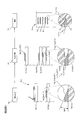
実施例3として図2Dに示す素子10bは、実施例1と端縁部111b、121bが湾曲する円弧形状の断面となっている点が相違する。導体層が、一定の膜厚を有し、断面が短冊形状の導体層平面部110b、120bと、該導体層平面部の両側に、滑らかに湾曲する断面が円弧形状の導体層端縁部111b、121bを具備することを特徴とする。
比較例2として図3Aに示す素子10yは、比較例1と同様に導体層110y、120yが四角形状の端面を有するが、端面位置が揃えられていない点が相違する。
実施例4として図3Bに示す素子10cは、実施例1と同様に導体層110c、120cには、先細りとなる三角形状(鈍角)の断面を有する端縁部111c、121cが形成されているが、端縁部111c、121cの位置は揃えられていない点が相違する。
実施例4として図3Bに示す素子10cは、実施例1と同様に導体層110c、120cには、先細りとなる三角形状(鈍角)の断面を有する端縁部111c、121cが形成されているが、端縁部111c、121cの位置は揃えられていない点が相違する。
実施例5として図3Cに示す素子10dは、実施例2と同様に導体層110d、120dには、先細りとなる三角形状(鋭角)の断面を有する端縁部111d、121dが形成されているが、端縁部111d、121dの位置は揃えられていない点が相違する。
実施例6として図3Dに示す素子10eは、実施例3と同様に、端縁部111e、121eが湾曲する円弧形状の断面となっているが、端縁部111e、121eの位置は揃えられていない点が相違する。
実施例6として図3Dに示す素子10eは、実施例3と同様に、端縁部111e、121eが湾曲する円弧形状の断面となっているが、端縁部111e、121eの位置は揃えられていない点が相違する。
ここで、図4A、図4B、図4C、図4D、図5A、図5B、図5C、図5Dを参照して、一対の導体層間に一定の電圧を印加したときに検出部平面上に発生する電界強度分布について、比較例1、実施例1~3、比較例2、実施例4~6におけるシミュレーション結果の違いについて説明する。
図4Aに示すように、比較例1では、導体層11z、12zの角部に強い電界集中が起こり、一対の平面部110z、120z間の電界強度が均一になる領域における電界強度が相対的に低くなることが判明した。
図4Bに示すように、実施例1では、電界集中部がそれぞれの端縁部111、121の3箇所に分散され、電界集中の割合が相対的に低くなり、その分、平面部110、120間で電界強度が均一になる領域における電荷強度が相対的に高くなることが判明した。
図4Aに示すように、比較例1では、導体層11z、12zの角部に強い電界集中が起こり、一対の平面部110z、120z間の電界強度が均一になる領域における電界強度が相対的に低くなることが判明した。
図4Bに示すように、実施例1では、電界集中部がそれぞれの端縁部111、121の3箇所に分散され、電界集中の割合が相対的に低くなり、その分、平面部110、120間で電界強度が均一になる領域における電荷強度が相対的に高くなることが判明した。
図4Cに示すように、実施例2では、さらに、電界集中が抑制され、その分、平面部110a、120a間の電界強度が均一になる領域における電荷強度が最も高くなることが判明した。
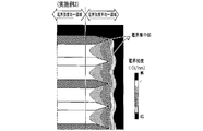
図4Dに示すように、実施例3でも、電界集中が抑制され平面部110b、120b間の電界強度が均一になる領域における電荷強度が相対的に高くなることが判明した。
図4Dに示すように、実施例3でも、電界集中が抑制され平面部110b、120b間の電界強度が均一になる領域における電荷強度が相対的に高くなることが判明した。
次いで、端面位置を揃えない場合を見ると、図5Aに示すように、比較例2では、比較例1よりも電界集中が抑制され、一対の平面部110y、120y間の電界強度が均一になる領域における電界強度は、比較例1よりは、相対的に高くなることが判明した。
一方、実施例4、5では、実施例1、2よりも却って電荷集中を招き、一対の平面部110c、110d、120c、120d間の電界強度が均一になる領域における電界強度は、実施例1、2より、相対的に低くなることが判明した。
しかし、実施例6では、実施例3よりも、電界集中が抑制され、一対の平面部110e、120e間の電界強度が均一になる領域における電界強度は、実施例3より、相対的に高くなることが判明した。
しかし、実施例6では、実施例3よりも、電界集中が抑制され、一対の平面部110e、120e間の電界強度が均一になる領域における電界強度は、実施例3より、相対的に高くなることが判明した。
ここで、図6を参照して、本開示の実施例7における素子10fについて説明する。
本実施例においては、検出部13fにおいて、端縁部111f、121fの全部、及び、平面部110f、120fの一部で、電界強度が不均一となる領域を覆うように、ガラス、アルミナ等の公知の絶縁性材料、若しくは、絶縁層100と同材質からなる遮蔽層14を設けてある。
なお、遮蔽層14を設ける構成は、前述の実施例1~6のいずれにも採用し得るものである。
本実施例においては、検出部13fにおいて、端縁部111f、121fの全部、及び、平面部110f、120fの一部で、電界強度が不均一となる領域を覆うように、ガラス、アルミナ等の公知の絶縁性材料、若しくは、絶縁層100と同材質からなる遮蔽層14を設けてある。
なお、遮蔽層14を設ける構成は、前述の実施例1~6のいずれにも採用し得るものである。
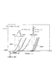
ここで、図7A、図7Bを参照して、本開示の効果の確認のために行った試験結果について説明する。 被測定ガス流路内に、素子10の検出部13を露出させ、電源部2から所定の電圧を印加し、既知量の粒子状物質を流した場合に、検出部13に一定量以上の粒子状物質が堆積するまで、粒子状物質の検出ができない不感質量Q0(不感期間)が存在する。
そこで、前述の比較例1、比較例2、実施例1~7に加え、比較例1と同様の導体層を中間層を設けないで形成した比較例3と、比較例2に前述の遮蔽層14を設けた比較例4、実施例6に遮蔽層を設けた実施例8について既知量の粒子状物質を投入した場合に、各実施例及び比較例のそれぞれに複数のサンプルを用意し、粒子状物質が検出されるまでの不感質量Q0を測定した。
そこで、前述の比較例1、比較例2、実施例1~7に加え、比較例1と同様の導体層を中間層を設けないで形成した比較例3と、比較例2に前述の遮蔽層14を設けた比較例4、実施例6に遮蔽層を設けた実施例8について既知量の粒子状物質を投入した場合に、各実施例及び比較例のそれぞれに複数のサンプルを用意し、粒子状物質が検出されるまでの不感質量Q0を測定した。
図7Aに示すように、比較例1では、不感質量Q0の平均値μ2が小さく、早期に粒子状物質の検出が可能となるが、サンプル間のバラツキσ2が大きいことが判明した。
一方、実施例1では、不感質量Q0の平均値μ1は、比較例1の不感質量よりも大きいが、サンプル間のバラツキσ1が遙かに小さいことが判明した。
これは、比較例1では、導体層11z、12zの端面の角部に強い電界の集中が起こり、その表面に集まった電荷に粒子状物質が引きつけられ、局所的に堆積するため早期に導通パスが形成されるためと推察される。
一方、実施例1では、不感質量Q0の平均値μ1は、比較例1の不感質量よりも大きいが、サンプル間のバラツキσ1が遙かに小さいことが判明した。
これは、比較例1では、導体層11z、12zの端面の角部に強い電界の集中が起こり、その表面に集まった電荷に粒子状物質が引きつけられ、局所的に堆積するため早期に導通パスが形成されるためと推察される。
しかし、角部における電界集中はサンプル間の変動が大きく、安定しないものと考えられる。
そこで、変動係数を用いたサンプルの評価を行った。具体的には、変動係数CV(100√σ2/μ)(%)を計算することにより、各サンプルの評価を行った。その評価結果を図7Bに示す。
比較例2では、比較例1よりは、バラツキが小さくなっているが、実施例1~7のいずれも、比較例1~4よりも、変動係数を小さくすることができ、本開示がセンサとしての信頼性の向上を図る効果を有するものであることが分かる。
そこで、変動係数を用いたサンプルの評価を行った。具体的には、変動係数CV(100√σ2/μ)(%)を計算することにより、各サンプルの評価を行った。その評価結果を図7Bに示す。
比較例2では、比較例1よりは、バラツキが小さくなっているが、実施例1~7のいずれも、比較例1~4よりも、変動係数を小さくすることができ、本開示がセンサとしての信頼性の向上を図る効果を有するものであることが分かる。
導体層11、12の両端面に断面が三角形状や円弧形状の端縁部111、121、111a、121a、111b、121b、111c、121c、111d、121d、111e、121eを設けることで、電界の集中を抑制し、導体層11、12の端部への局所的な粒子状物質の堆積が抑制されるものと考えられる。
加えて、端縁部111a、121aでは、断面鋭角三角形状となっているので、電界集中の起こりやすい頂点間の距離が長くなるため、一対の端縁部111a、121a間に導通パスが形成されるまでの時間も長くなるものと推察される。
加えて、端縁部111a、121aでは、断面鋭角三角形状となっているので、電界集中の起こりやすい頂点間の距離が長くなるため、一対の端縁部111a、121a間に導通パスが形成されるまでの時間も長くなるものと推察される。
ここで、図8A、図8B、図8C、図8Dを参照して、前述の比較例1、比較例2、実施例1、実施例2として示した粒子状物質検出素子10z、10y、10、10aのそれぞれの製造方法について説明する。
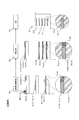
比較例1は、導体層11z、12zと絶縁層100zとを交互に積層して断面を検出部13zとして利用する粒子状物質検出素子10zの基本的な製造方法を示している。
比較例1は、導体層11z、12zと絶縁層100zとを交互に積層して断面を検出部13zとして利用する粒子状物質検出素子10zの基本的な製造方法を示している。
アルミナ等の絶縁性材料を、公知の結合材、可塑剤、分散剤、溶剤等と混合、攪拌してスラリーを形成し、ドクターブレード法などの公知の製法によって、シート状に形成し、絶縁性シート100zGSを得る。
これを、図略の打ち抜き工程P0zにおいて、予め、金型等を用いて、印刷の位置あわせのためのガイドや、極性が共通する導体層同士を接続するためのスルーホール電極114z、124zを埋設するためのスルーホール等を必要に応じて穿設すると共に、所定の外形形状に打ち抜く。
これを、図略の打ち抜き工程P0zにおいて、予め、金型等を用いて、印刷の位置あわせのためのガイドや、極性が共通する導体層同士を接続するためのスルーホール電極114z、124zを埋設するためのスルーホール等を必要に応じて穿設すると共に、所定の外形形状に打ち抜く。
印刷工程P1zでは、導体ペーストを所定の導体パターンを形成した厚膜印刷用スクリーンから吐出して、導体層印刷膜11zPRT、12zPRTを絶縁層シート100zGSに転写する。
このとき、円内に拡大して示すように、ペーストのレオロジー特性と表面張力の影響により、極僅かではあるが、中心付近の膜厚が薄くなり、外周付近の膜厚が厚くなる。
このとき、円内に拡大して示すように、ペーストのレオロジー特性と表面張力の影響により、極僅かではあるが、中心付近の膜厚が薄くなり、外周付近の膜厚が厚くなる。
比較例1では、絶縁層100zを構成する絶縁性材料と同材料を含むペーストを用いて、厚膜印刷により、導体層印刷膜11zPRT、12zPRTと同じ膜厚で、導体層以外の部分を覆うように中間層101zを形成している。
続く、積層圧着工程P2zでは、導体層印刷膜11zPRT、12zPRTの極性が交互に入れ替わるように絶縁層シート100zGSを積み重ね、金型等を用いて圧着する。
続く、積層圧着工程P2zでは、導体層印刷膜11zPRT、12zPRTの極性が交互に入れ替わるように絶縁層シート100zGSを積み重ね、金型等を用いて圧着する。
このようにして得られた積層構造体を焼成工程P3zにおいて、導体層11z、12zと絶縁層100zとを同時に焼成し一体とする。
その後、切削、研磨等により、導体層11z、12zの断面を露出させ検出部13zとした素子10zが完成する。
その後、切削、研磨等により、導体層11z、12zの断面を露出させ検出部13zとした素子10zが完成する。
比較例1では、中間層101zが設けられているため、積層圧着時に導体層印刷膜11zPRT、12zPRT及び導体層シート110zの変形がほとんどなく、素子10zの機械的強度は優れているが、導体層11z、12zは、断面短冊状の形状が維持されている。
しかし、両導体層間に電圧を印加したときには、角部への電界の集中が大きく、前述の如く、不感質量のバラツキが大きいことが判明した。
なお、比較例2として示す素子10yは、比較例1と同様の製造法を基本とし、積層圧着工程において、導体層11y、12y端面の位置を意図的にずらして積層したものである。
しかし、両導体層間に電圧を印加したときには、角部への電界の集中が大きく、前述の如く、不感質量のバラツキが大きいことが判明した。
なお、比較例2として示す素子10yは、比較例1と同様の製造法を基本とし、積層圧着工程において、導体層11y、12y端面の位置を意図的にずらして積層したものである。
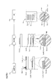
図8Bを参照して、比較例3として示した素子10xの製造工程の概要と、比較例3の問題点について説明する。
比較例3では、印刷工程P1xに示すように、所定形状に打ち抜いた絶縁層シート100xGSに、導体層110x、120xの印刷のみを行い、中間層を設けることなく、積層圧着工程P2xに進む。
比較例3では、印刷工程P1xに示すように、所定形状に打ち抜いた絶縁層シート100xGSに、導体層110x、120xの印刷のみを行い、中間層を設けることなく、積層圧着工程P2xに進む。
積層圧着工程P2xでは、導体層印刷膜11xPRT、12xPRTが、絶縁層シート100xGSよりも硬いため、積層圧着時には、絶縁層シート100xGSが弾性変形し、導体層印刷膜11xPRT、12xPRTが、絶縁層シート100xGS内にめり込むようにして絶縁層シート100xGS同士が密着する。
このとき、導体層印刷膜11xPRT、12xPRTの両側には、図8Bの積層圧着工程P2xの円内に拡大して示すように、断面三角形状の空隙が形成される。
このとき、導体層印刷膜11xPRT、12xPRTの両側には、図8Bの積層圧着工程P2xの円内に拡大して示すように、断面三角形状の空隙が形成される。
その後の焼成工程P3xによって、空隙の表面積を小さくするように焼結がするむので、空隙は縮小されるが、完全には消滅せず、ボイドとして残留したり、デラミネーションのきっかけとなったりする虞がある。
また、焼成後の導体層11x、12xの端面は、多角形やいびつな形状となり、前述の比較例2と同様、角部に電界の集中が起こり易くなる。
また、焼成後の導体層11x、12xの端面は、多角形やいびつな形状となり、前述の比較例2と同様、角部に電界の集中が起こり易くなる。
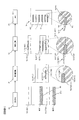
図8Cを参照して、本開示の実施例1の製造工程の概要について説明する。
本実施形態においては、比較例1と同様の工程により、形成した絶縁層シート100GSに、位置決めのためのガイドと必要に応じたスルーホールを穿設すると共に、所定の外形形状に打ち抜く、打ち抜き工程P0において、絶縁層シート100GSの打ち抜きと同時に、導体層110、120を印刷形成する位置に合わせて、所定の導体層端縁部111、121の形状に合わせた凹み部101を設けた凹みシート100PCDを形成する。
具体的には、打ち抜き用の金型に、凹み部101を形成するための突起を設けて、絶縁層シート100GSの表面を押圧する。
これにより、導体層端縁部111、121を形成する部分に所望の角度で傾斜するテーパ面を形成することができる。
本実施形態においては、比較例1と同様の工程により、形成した絶縁層シート100GSに、位置決めのためのガイドと必要に応じたスルーホールを穿設すると共に、所定の外形形状に打ち抜く、打ち抜き工程P0において、絶縁層シート100GSの打ち抜きと同時に、導体層110、120を印刷形成する位置に合わせて、所定の導体層端縁部111、121の形状に合わせた凹み部101を設けた凹みシート100PCDを形成する。
具体的には、打ち抜き用の金型に、凹み部101を形成するための突起を設けて、絶縁層シート100GSの表面を押圧する。
これにより、導体層端縁部111、121を形成する部分に所望の角度で傾斜するテーパ面を形成することができる。
その結果、印刷工程P1において、通常の厚膜印刷を行っても、導体層端縁部111、121の絶縁層シート100GSに接する側が凹み部101の形状に沿って傾斜することになる。
また、凹みシート100PCDの下面側にも凹み部101が形成されているので、積層圧着工程P1において積み重ねたときに、導体層印刷膜110、120との密着性が向上し、比較例2のようなボイドが形成されることがない。
また、凹みシート100PCDの下面側にも凹み部101が形成されているので、積層圧着工程P1において積み重ねたときに、導体層印刷膜110、120との密着性が向上し、比較例2のようなボイドが形成されることがない。
さらに、比較例1に用いたような中間層を設けなくても、絶縁層シート100GS同士を簡単に密着させることができる。
その結果、焼成工程P3により、導体層11、12と絶縁層100とを一体化したときに、デラミネーションの起こり難い素子10を形成することができる。
加えて、導体層端縁部111、121を断面先細りとなる三角形状に形成することが可能となるので、電界の集中を抑制した素子10の実現が容易である。
その結果、焼成工程P3により、導体層11、12と絶縁層100とを一体化したときに、デラミネーションの起こり難い素子10を形成することができる。
加えて、導体層端縁部111、121を断面先細りとなる三角形状に形成することが可能となるので、電界の集中を抑制した素子10の実現が容易である。
図8Dを参照して本開示の実施例2の製造工程の概要について説明する。
本実施形態における導体印刷工程P1aにおいては、絶縁層シート100(GS)に導体層11、12を印刷形成する際に、部分的にメッシュ開口率を変化させて所定の位置において印刷の膜厚が薄くなるように設定した開口率部分変更印刷用スクリーンPPM、PPMAを用いている点が前記実施形態と相違する。
開口率部分変更印刷用スクリーンPPM、PPMAについては、図9A、図9B、図10を参照して後述する。本実施形態においては、開口率部分変更印刷用スクリーンPPMを用いることで、開効率を低く設定した部分から吐出される導体ペーストの量が抑制され、これによって形成される導体層の膜厚を薄くすることができ、外側に向かって先細りとなり鋭角の傾斜面を有する断面三角形状の導体層端縁部111a、121aを形成することができる。
本実施形態における導体印刷工程P1aにおいては、絶縁層シート100(GS)に導体層11、12を印刷形成する際に、部分的にメッシュ開口率を変化させて所定の位置において印刷の膜厚が薄くなるように設定した開口率部分変更印刷用スクリーンPPM、PPMAを用いている点が前記実施形態と相違する。
開口率部分変更印刷用スクリーンPPM、PPMAについては、図9A、図9B、図10を参照して後述する。本実施形態においては、開口率部分変更印刷用スクリーンPPMを用いることで、開効率を低く設定した部分から吐出される導体ペーストの量が抑制され、これによって形成される導体層の膜厚を薄くすることができ、外側に向かって先細りとなり鋭角の傾斜面を有する断面三角形状の導体層端縁部111a、121aを形成することができる。
このように、断面三角形状の導体層端縁部111a、121aを有する導体層11a、12aを形成した絶縁層シート100GSを積み重ね金型等を用いて圧着することで、導体層11a、12aが絶縁層100GSにめり込みながら、絶縁層100GS同士が密着状態となる。
このとき、導体層端縁部111a、121aが、先細りの三角形状となっているので、比較例2に示したような空隙が形成されることがない。
このようにしてできあがった積層構造体を焼成工程P3aで焼成することにより、導体端面付近の電界の集中を抑制した素子10aを極めて容易に形成することができる。
このとき、導体層端縁部111a、121aが、先細りの三角形状となっているので、比較例2に示したような空隙が形成されることがない。
このようにしてできあがった積層構造体を焼成工程P3aで焼成することにより、導体端面付近の電界の集中を抑制した素子10aを極めて容易に形成することができる。
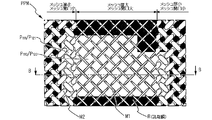
図9A、図9Bを参照して、本開示の粒子状物質検出素子10の製造において、用いられる開口率部分低下スクリーンMの特徴と、これを用いたときに形成される導体層11、12の形状について説明する。
なお、本図においては、一対の導体層11、12の内、一方の導体層平面部110、導体層端縁部111を形成するパターンのみを示しているが、他方の導体層平面部120、導体層端縁部121は、一方のパターンを左右反転したパターンとなるので、他方を省略し、共通する構成について符号を110/120のように並べて記載してある。
なお、本図においては、一対の導体層11、12の内、一方の導体層平面部110、導体層端縁部111を形成するパターンのみを示しているが、他方の導体層平面部120、導体層端縁部121は、一方のパターンを左右反転したパターンとなるので、他方を省略し、共通する構成について符号を110/120のように並べて記載してある。
本実施形態においては、一般的に厚膜印刷に用いられている厚膜印刷用スクリーンの一部を圧延して部分的に平坦化し、メッシュ厚を薄くすると共にメッシュ開口率を小さくした開口率部分低下スクリーンMを用いている。
レジスト膜Rは、一般的な厚膜印刷と同様、印刷用スクリーンに乳剤を塗布し、導体層平面部110、120の形状に合わせたパターンを露光、硬化して、所定の印刷パターンに形成されている。
図9A、図9Bに示すように、導体層端縁部111、121を印刷形成する部分のマスクM2の断面方向の厚さは薄く、平面方向の線幅が広くなっているので、導体層端縁部111、121を印刷形成する部分の開口率、即ち、端縁部形成用開口率P111、P121は、導体層平面部110を形成する部分のマスクM1の開口率、即ち、平面部形成用開効率P111、P121よりも低くなっている。
このため、図9Bに示すように、導体層平面部110、120を印刷形成したときに、マスクM2から吐出するペースト量が少なくなり、導体層端縁部111、121の膜厚は、導体層平面部110、120の膜厚より薄くなる。
レジスト膜Rは、一般的な厚膜印刷と同様、印刷用スクリーンに乳剤を塗布し、導体層平面部110、120の形状に合わせたパターンを露光、硬化して、所定の印刷パターンに形成されている。
図9A、図9Bに示すように、導体層端縁部111、121を印刷形成する部分のマスクM2の断面方向の厚さは薄く、平面方向の線幅が広くなっているので、導体層端縁部111、121を印刷形成する部分の開口率、即ち、端縁部形成用開口率P111、P121は、導体層平面部110を形成する部分のマスクM1の開口率、即ち、平面部形成用開効率P111、P121よりも低くなっている。
このため、図9Bに示すように、導体層平面部110、120を印刷形成したときに、マスクM2から吐出するペースト量が少なくなり、導体層端縁部111、121の膜厚は、導体層平面部110、120の膜厚より薄くなる。
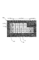
図10を参照して、開口率部分低下スクリーンの変形例MAについて説明する。
前記実施形態においては、厚膜印刷用スクリーンの一部を加圧して、開口率を低くした開口率部分低下スクリーンMを例として示したが、本図に示すように、開口率部分低下スクリーンMAでは、導体層平面部110、120を印刷するマスクM1Aに比べて導体層端縁部111、121を印刷するマスクM2Aの横糸と縦糸の織り込み密度を高くすることで端縁部形成用開口率P111A/P121Aを平面部形成用開口率P110A/P120Aよりも低くしてある
本実施形態における開口率部分低下スクリーンMAでは、予め開口率を部分的に調整したスクーリンメッシュに所定の導体パターンとなるようレジストRを形成してある。
前記実施形態においては、厚膜印刷用スクリーンの一部を加圧して、開口率を低くした開口率部分低下スクリーンMを例として示したが、本図に示すように、開口率部分低下スクリーンMAでは、導体層平面部110、120を印刷するマスクM1Aに比べて導体層端縁部111、121を印刷するマスクM2Aの横糸と縦糸の織り込み密度を高くすることで端縁部形成用開口率P111A/P121Aを平面部形成用開口率P110A/P120Aよりも低くしてある
本実施形態における開口率部分低下スクリーンMAでは、予め開口率を部分的に調整したスクーリンメッシュに所定の導体パターンとなるようレジストRを形成してある。
これによって、導体層11、12を印刷したときに、導体層端縁部111、121において、マスクM2Aから吐出される導体ペースト量が抑制され、導体層平面部110、120よりも薄い膜厚に形成することができる。また、外側に向かって織り込み密度を徐々に高くすることで、導体層端縁部111、121の膜厚を外側に向かって徐々に薄くすることが可能となり、先細りの断面三角形状とすることができる。
なお、前記実施形態においては、打ち抜き工程P0と印刷工程P1とのそれぞれで、導体層端縁部111、121を所望の形状にできる方法を示したが、これらを組み合わせることも可能である。
また、積層圧着工程では、導体層11、12を乾燥した後に、積層圧着する場合を例としたが、導体層11、12が未乾燥の状態で、積層圧着するようにしても良い。
特に、打ち抜き工程P0で、絶縁層シート100(GS)に、凹み部10を設けた場合、導体層11、12が未乾燥状態で積層圧着すると、凹み部10の形状に合わせて、導体層11、12が流動変形するので、導体層端縁部111、121を所望の形状に形成することができる。
また、積層圧着工程では、導体層11、12を乾燥した後に、積層圧着する場合を例としたが、導体層11、12が未乾燥の状態で、積層圧着するようにしても良い。
特に、打ち抜き工程P0で、絶縁層シート100(GS)に、凹み部10を設けた場合、導体層11、12が未乾燥状態で積層圧着すると、凹み部10の形状に合わせて、導体層11、12が流動変形するので、導体層端縁部111、121を所望の形状に形成することができる。
また、前記実施形態においては、積層圧着工程P3において、比較例1に示したような絶縁性材料からなる中間層101を用いない方法を示したが、導体層端縁部111、121の形状が予め、先細り三角形状の断面や緩やかに湾曲する円弧形状の断面となるように形成されている場合には、印刷工程で絶縁性材料からなるペーストを用いて中間層101を印刷形成するようにしても良い。
中間層101を用いることで、積層圧着時における絶縁層シート100に作用する剪断応力を緩和し、素子10の機械的強度を向上したり、焼成時に亀裂の発生を抑制したりできる。
検出精度の向上に加え、素子10の耐久性向上を図る効果が期待できる。
中間層101を用いることで、積層圧着時における絶縁層シート100に作用する剪断応力を緩和し、素子10の機械的強度を向上したり、焼成時に亀裂の発生を抑制したりできる。
検出精度の向上に加え、素子10の耐久性向上を図る効果が期待できる。
1 粒子状物質検出センサ
10 粒子状物質検出素子
100 絶縁層
11、12 導体層
110、120 導体層平面部
111、121 導体層端縁部
13 検出部
14 絶縁保護層
2 電源部
3 測定部
P0 打ち抜き工程
P1 導体層印刷工程
P2 積層圧着工程
P3 焼成工程
P111、P111A、P121、P121A 端縁部形成用開口率
P110、P110A、P120、P120A 平面部形成用開口率
M、MA 開口率部分低下スクリーン
10 粒子状物質検出素子
100 絶縁層
11、12 導体層
110、120 導体層平面部
111、121 導体層端縁部
13 検出部
14 絶縁保護層
2 電源部
3 測定部
P0 打ち抜き工程
P1 導体層印刷工程
P2 積層圧着工程
P3 焼成工程
P111、P111A、P121、P121A 端縁部形成用開口率
P110、P110A、P120、P120A 平面部形成用開口率
M、MA 開口率部分低下スクリーン
Claims (8)
- 堆積する粒子状物質の量によって変化する電気的特性を計測し、被測定ガス中の粒子状物質を検出するための粒子状物質検出素子であって、
平板状の導体層(11、11a、11c、11d、11f、12、12a、12c、12d、12f)と、
平板状の絶縁層(100、100a、100c、100c、100d、100f)と、
前記導体層と前記絶縁層を交互に積み重ねた積層構造と、
前記積層構造の断面に、前記導体層を極性の異なる一対の検出電極を有し前記粒子状物質が堆積する検出部(13、13a、13c、13d、13f)と、を有し、
前記導体層は、一定膜厚を有し、断面短冊形状の導体層平面部(110、110a、110c、110d、110f、120、120a、120c、120d、120f)と、該導体層平面部の両側に、先細りとなる断面三角形状の導体層端縁部(111、111a、111c、111d、111f、121、121a、121c、121d、121f)を備えること特徴とする粒子状物質検出素子(10、10a、10c、10d、10f)。 - 堆積する粒子状物質の量によって変化する電気的特性を計測し、被測定ガス中の粒子状物質を検出するための粒子状物質検出素子であって、
平板状の導体層(11b、11e、11g、12b、12e、12g)と、
平板状の絶縁層(100b、100e、100g)と、
前記導体層と前記絶縁層を交互に積み重ねた積層構造と、
前記積層構造の断面に、前記導体層を極性の異なる一対の検出電極を有し前記粒子状物質が堆積する検出部(13b、13e、13g)と、を有し、
前記導体層が、一定膜厚を有し、断面短冊形状の導体層平面部(110b、110e、110g、120b、120e、120g)と、該導体層平面部の両側に、滑らかに湾曲する断面円弧形状の導体層端縁部(111b、111e、111g、121b、121e、121g)を具備することを特徴とする粒子状物質検出素子(10b、10e、10g)。 - 絶縁性材料からなり、前記導体層端縁部の全部と前記導体層平面部の一部を覆う遮蔽層(14)を具備する請求項1又は2に記載の粒子状物質検出素子(10f、10g)。
- 被測定ガス中に存在する粒子状物質を検出する粒子状物質検出センサであって、請求項1ないし3のいずれかに記載の粒子状物質検出素子(10、10a~10g)と、前記一対の検出電極の間に電圧を印加する電源部(2)と、該電源部から前記検出電極間への電圧の印加により発生する電界を被測定ガス中に存在する粒子状物質に作用させて前記検出部へ捕集し、前記検出部への粒子状物質の堆積に伴い変化する前記一対の検出電極間の電気的特性を計測する計測部(3)とを具備する粒子状物質検出センサ(1、1a~1g)。
- 請求項1ないし3のいずれかに記載の粒子状物質検出素子の製造方法であって、
少なくとも、絶縁性材料からなる絶縁層シートに位置決めのためのガイドと必要に応じたスルーホールを穿設すると共に、所定の外形形状に打ち抜く、打ち抜き工程(P0)と、
該打ち抜き工程で得られた絶縁層シート(100GS)に導電性材料からなる導体ペーストを所定の導体層パターンを形成した厚膜印刷用スクリーンから吐出させて所定の形状の導体層印刷膜(11PRT、11aPRT、12PRT、12aPRT)を形成する厚膜印刷工程(P1)と、
該厚膜印刷工程で得られた導体層を施した絶縁層シートを積み重ねて圧着する積層圧着工程(P2)と、
該積層圧着工程で得られた積層構造体を焼成し一体とする焼成工程(P3)とを具備し、
前記打ち抜き工程が、前記絶縁層シートの打ち抜きと同時に、前記導体層を印刷形成する位置に合わせて、所定の導体層端縁部の形状に合わせた凹み部(101)を設けた凹みシート(100PCD)を形成することを特徴とする粒子状物質検出素子の製造方法。 - 請求項1ないし3のいずれかに記載の粒子状物質検出素子の製造方法であって、少なくとも、絶縁性材料からなる絶縁層シートに位置決めのためのガイドと必要に応じたスルーホールを穿設すると共に、所定の外形形状に打ち抜く、打ち抜き工程(P0)と、
該打ち抜き工程で得られた絶縁層シートに導電性材料からなる導体ペーストを所定の導体層パターンを形成した厚膜印刷用スクリーンから吐出させて所定の形状の導体層印刷膜を形成する厚膜印刷工程(P1)と、
該厚膜印刷工程で得られた導体層を施した絶縁層シートを積み重ねて圧着する積層圧着工程(P2)と、
該積層圧着工程で得られた積層構造体を焼成し一体とする焼成工程(P3)とを具備し、
前記厚膜印刷工程(P1)において、所定の導体層端縁部(111PRT、121PRT)の形状に合わせて、前記厚膜印刷用スクリーンの前記導体層端縁部を形成する位置における開口率、即ち、端縁部形成用開口率(P111、P111A、P121、P121A)を、前記導体層平面部を形成するための位置における開口率、即ち、平面部形成用開口率(P110、P110A、P120、P120A)をよりも低くした開口率部分低下スクリーン(M、MA)を用いることを特徴とする粒子状物質検出素子の製造方法。 - 請求項1ないし3のいずれかに記載の粒子状物質検出素子の製造方法であって、
少なくとも、絶縁性材料からなる絶縁層シートに位置決めのためのガイドと必要に応じたスルーホールを穿設すると共に、所定の外形形状に打ち抜く、打ち抜き工程(P0)と、
該打ち抜き工程で得られた絶縁層シート(100GS)に導電性材料からなる導体ペーストを所定の導体層パターンを形成した厚膜印刷用スクリーンから吐出させて所定の形状の導体層印刷膜(11PRT、11aPRT、12PRT、12aPRT)を形成する厚膜印刷工程(P1)と、
該厚膜印刷工程で得られた導体層を施した絶縁層シートを積み重ねて圧着する積層圧着工程(P2)と、該積層圧着工程で得られた積層構造体を焼成し一体とする焼成工程(P3)とを具備し、
前記打ち抜き工程が、前記絶縁層シートの打ち抜きと同時に、前記導体層を印刷形成する位置に合わせて、所定の導体層端縁部の形状に合わせた凹み部(101)を設けた凹みシート(100PCD)を形成し、かつ、 前記厚膜印刷工程において、所定の導体層端縁部(111PRT、121PRT)の形状に合わせて、前記厚膜印刷用スクリーンの前記導体層端縁部を形成する位置における開口率、即ち、端縁部形成用開口率(P111、P111A、P121、P121A)を、前記導体層平面部を形成するための位置における開口率、即ち、平面部形成用開口率(P110、P110A、P120、P120A)をよりも低くした開口率部分低下スクリーン(M、MA)を用いることを特徴とする粒子状物質検出素子の製造方法。 - 前記積層圧着工程において、前記導体層が、未乾燥状態の内に積層圧着を行う請求項5ないし7のいずれかに記載の粒子状物質検出素子の製造方法。
Priority Applications (5)
| Application Number | Priority Date | Filing Date | Title |
|---|---|---|---|
| US15/110,447 US10520415B2 (en) | 2014-01-10 | 2015-01-09 | Particulate matter detection element, particulate matter detection sensor, and method of manufacturing particulate matter detection element |
| CN201580004118.4A CN105899934B (zh) | 2014-01-10 | 2015-01-09 | 颗粒状物质检测元件、颗粒状物质检测传感器以及颗粒状物质检测元件的制造方法 |
| EP15734833.5A EP3093648A4 (en) | 2014-01-10 | 2015-01-09 | Particulate substance detection element, particulate substance detection sensor, and method for manufacturing particulate substance detection element |
| US16/191,489 US20190078991A1 (en) | 2014-01-10 | 2018-11-15 | Particulate matter detection element, particulate matter detection sensor, and method of manufacturing particulate matter detection element |
| US16/687,737 US11231354B2 (en) | 2014-01-10 | 2019-11-19 | Method of manufacturing particulate matter detection element |
Applications Claiming Priority (2)
| Application Number | Priority Date | Filing Date | Title |
|---|---|---|---|
| JP2014-002882 | 2014-01-10 | ||
| JP2014002882A JP6228018B2 (ja) | 2014-01-10 | 2014-01-10 | 粒子状物質検出素子、粒子状物質検出センサ並びに粒子状物質検出素子の製造方法 |
Related Child Applications (3)
| Application Number | Title | Priority Date | Filing Date |
|---|---|---|---|
| US15/110,447 A-371-Of-International US10520415B2 (en) | 2014-01-10 | 2015-01-09 | Particulate matter detection element, particulate matter detection sensor, and method of manufacturing particulate matter detection element |
| US16/191,489 Division US20190078991A1 (en) | 2014-01-10 | 2018-11-15 | Particulate matter detection element, particulate matter detection sensor, and method of manufacturing particulate matter detection element |
| US16/687,737 Division US11231354B2 (en) | 2014-01-10 | 2019-11-19 | Method of manufacturing particulate matter detection element |
Publications (1)
| Publication Number | Publication Date |
|---|---|
| WO2015105182A1 true WO2015105182A1 (ja) | 2015-07-16 |
Family
ID=53524005
Family Applications (1)
| Application Number | Title | Priority Date | Filing Date |
|---|---|---|---|
| PCT/JP2015/050508 Ceased WO2015105182A1 (ja) | 2014-01-10 | 2015-01-09 | 粒子状物質検出素子、粒子状物質検出センサ並びに粒子状物質検出素子の製造方法 |
Country Status (5)
| Country | Link |
|---|---|
| US (3) | US10520415B2 (ja) |
| EP (1) | EP3093648A4 (ja) |
| JP (1) | JP6228018B2 (ja) |
| CN (1) | CN105899934B (ja) |
| WO (1) | WO2015105182A1 (ja) |
Cited By (2)
| Publication number | Priority date | Publication date | Assignee | Title |
|---|---|---|---|---|
| CN106053308A (zh) * | 2016-07-07 | 2016-10-26 | 中国第汽车股份有限公司 | 一种片式车用颗粒物传感器芯片及其制作方法 |
| CN107850525A (zh) * | 2015-10-20 | 2018-03-27 | 宝马股份公司 | 炭烟颗粒传感器 |
Families Citing this family (10)
| Publication number | Priority date | Publication date | Assignee | Title |
|---|---|---|---|---|
| JP6228018B2 (ja) | 2014-01-10 | 2017-11-08 | 株式会社Soken | 粒子状物質検出素子、粒子状物質検出センサ並びに粒子状物質検出素子の製造方法 |
| JP6441161B2 (ja) * | 2015-04-28 | 2018-12-19 | 株式会社デンソー | 粒子状物質検出センサ |
| US9951672B2 (en) * | 2015-11-10 | 2018-04-24 | Ford Global Technologies, Llc | Method and system for exhaust particulate matter sensing |
| US10768131B2 (en) * | 2015-11-25 | 2020-09-08 | Kyocera Corporation | Sensor substrate arrangement for a particulate sensor device |
| JP6068738B1 (ja) * | 2016-09-16 | 2017-01-25 | キヤノンアネルバ株式会社 | 加熱装置、基板加熱装置および半導体デバイスの製造方法 |
| JPWO2019049567A1 (ja) * | 2017-09-06 | 2020-10-29 | 日本碍子株式会社 | 微粒子検出素子及び微粒子検出器 |
| WO2019049566A1 (ja) * | 2017-09-06 | 2019-03-14 | 日本碍子株式会社 | 微粒子検出素子及び微粒子検出器 |
| JP2020008317A (ja) * | 2018-07-03 | 2020-01-16 | 新日本無線株式会社 | イオンセンサ |
| JP2020034349A (ja) * | 2018-08-28 | 2020-03-05 | イビデン株式会社 | 粒子状物質検出センサ素子 |
| JP2020034348A (ja) * | 2018-08-28 | 2020-03-05 | イビデン株式会社 | 粒子状物質検出センサ素子 |
Citations (8)
| Publication number | Priority date | Publication date | Assignee | Title |
|---|---|---|---|---|
| JPS60196659A (ja) | 1984-03-21 | 1985-10-05 | Hitachi Ltd | センサ用抵抗測定電極 |
| JPH07301616A (ja) * | 1994-04-29 | 1995-11-14 | Nippondenso Co Ltd | ガスセンサ |
| JP2008502892A (ja) | 2004-06-16 | 2008-01-31 | ローベルト ボツシユ ゲゼルシヤフト ミツト ベシユレンクテル ハフツング | センサ上の煤堆積の制御のための方法 |
| JP2011080926A (ja) * | 2009-10-09 | 2011-04-21 | Denso Corp | パティキュレート検出素子 |
| JP2012047596A (ja) * | 2010-08-26 | 2012-03-08 | Ngk Insulators Ltd | 粒子状物質検出装置 |
| JP2012078130A (ja) * | 2010-09-30 | 2012-04-19 | Denso Corp | 粒子状物質検出センサおよびその製造方法 |
| JP2012093292A (ja) * | 2010-10-28 | 2012-05-17 | Denso Corp | 粒子状物質検出素子 |
| JP2013231627A (ja) * | 2012-04-27 | 2013-11-14 | Nippon Soken Inc | 粒子状物質検出素子とその製造方法、並びに、粒子状物質検出センサ |
Family Cites Families (18)
| Publication number | Priority date | Publication date | Assignee | Title |
|---|---|---|---|---|
| US5008628A (en) * | 1989-06-05 | 1991-04-16 | Wahlco, Inc. | Measurement of electrical resistivity of particulate entrained in a gas stream |
| DE102005053120A1 (de) * | 2005-11-08 | 2007-05-10 | Robert Bosch Gmbh | Sensorelement für Gassensoren und Verfahren zum Betrieb desselben |
| JPWO2008062554A1 (ja) * | 2006-11-20 | 2010-03-04 | 株式会社東芝 | ガス浄化装置、ガス浄化システムおよびガス浄化方法 |
| CN201034969Y (zh) * | 2007-05-31 | 2008-03-12 | 李金波 | 微型电化学传感器 |
| DE102007029888B4 (de) * | 2007-06-28 | 2016-04-07 | Siemens Aktiengesellschaft | Bildgebendes Verfahren für die medizinische Diagnostik und nach diesem Verfahren arbeitende Einrichtung |
| US20090056416A1 (en) | 2007-08-30 | 2009-03-05 | Nair Balakrishnan G | Ceramic Particulate Matter Sensor With Low Electrical Leakage |
| CA2700507C (en) * | 2007-09-24 | 2018-05-29 | Bayer Healthcare Llc | Multi-region and potential test sensors, methods, and systems |
| US7966862B2 (en) * | 2008-01-28 | 2011-06-28 | Honeywell International Inc. | Electrode structure for particulate matter sensor |
| KR100999820B1 (ko) * | 2008-12-01 | 2010-12-08 | 조근호 | 직접인쇄방법으로 기판에 내열성 도전성 패턴을 형성하기 위한 페이스트 조성물 |
| CN101482528B (zh) * | 2009-01-23 | 2013-01-02 | 南京大学 | 一种可集成的密集纳米颗粒单层膜氢气传感器的制备方法 |
| US20130028388A1 (en) * | 2010-04-07 | 2013-01-31 | Shimadzu Corporation | Fluoroscopic x-ray apparatus |
| JP5225321B2 (ja) * | 2010-04-21 | 2013-07-03 | 関西オートメイション株式会社 | 粉粒体の流動計測装置 |
| JP5201194B2 (ja) * | 2010-10-28 | 2013-06-05 | 株式会社デンソー | 粒子状物質検出装置及び粒子状物質検出素子の製造方法 |
| JP5333675B2 (ja) * | 2011-03-16 | 2013-11-06 | トヨタ自動車株式会社 | 粒子状物質処理装置 |
| JP5418611B2 (ja) * | 2011-04-21 | 2014-02-19 | 株式会社デンソー | 粒子状物質検出装置の補正方法 |
| CN202611819U (zh) * | 2012-02-10 | 2012-12-19 | 金坛鸿鑫电子科技有限公司 | 一种提高测量精度的颗粒物传感器 |
| CN202974933U (zh) * | 2012-09-12 | 2013-06-05 | 江西恒盛晶微技术有限公司 | 一种用于一体化薄膜微电极生物传感器件的pH值测量电极 |
| JP6228018B2 (ja) | 2014-01-10 | 2017-11-08 | 株式会社Soken | 粒子状物質検出素子、粒子状物質検出センサ並びに粒子状物質検出素子の製造方法 |
-
2014
- 2014-01-10 JP JP2014002882A patent/JP6228018B2/ja active Active
-
2015
- 2015-01-09 WO PCT/JP2015/050508 patent/WO2015105182A1/ja not_active Ceased
- 2015-01-09 US US15/110,447 patent/US10520415B2/en active Active
- 2015-01-09 CN CN201580004118.4A patent/CN105899934B/zh not_active Expired - Fee Related
- 2015-01-09 EP EP15734833.5A patent/EP3093648A4/en not_active Withdrawn
-
2018
- 2018-11-15 US US16/191,489 patent/US20190078991A1/en not_active Abandoned
-
2019
- 2019-11-19 US US16/687,737 patent/US11231354B2/en not_active Expired - Fee Related
Patent Citations (8)
| Publication number | Priority date | Publication date | Assignee | Title |
|---|---|---|---|---|
| JPS60196659A (ja) | 1984-03-21 | 1985-10-05 | Hitachi Ltd | センサ用抵抗測定電極 |
| JPH07301616A (ja) * | 1994-04-29 | 1995-11-14 | Nippondenso Co Ltd | ガスセンサ |
| JP2008502892A (ja) | 2004-06-16 | 2008-01-31 | ローベルト ボツシユ ゲゼルシヤフト ミツト ベシユレンクテル ハフツング | センサ上の煤堆積の制御のための方法 |
| JP2011080926A (ja) * | 2009-10-09 | 2011-04-21 | Denso Corp | パティキュレート検出素子 |
| JP2012047596A (ja) * | 2010-08-26 | 2012-03-08 | Ngk Insulators Ltd | 粒子状物質検出装置 |
| JP2012078130A (ja) * | 2010-09-30 | 2012-04-19 | Denso Corp | 粒子状物質検出センサおよびその製造方法 |
| JP2012093292A (ja) * | 2010-10-28 | 2012-05-17 | Denso Corp | 粒子状物質検出素子 |
| JP2013231627A (ja) * | 2012-04-27 | 2013-11-14 | Nippon Soken Inc | 粒子状物質検出素子とその製造方法、並びに、粒子状物質検出センサ |
Cited By (4)
| Publication number | Priority date | Publication date | Assignee | Title |
|---|---|---|---|---|
| CN107850525A (zh) * | 2015-10-20 | 2018-03-27 | 宝马股份公司 | 炭烟颗粒传感器 |
| JP2018538521A (ja) * | 2015-10-20 | 2018-12-27 | バイエリシエ・モトーレンウエルケ・アクチエンゲゼルシヤフト | スートセンサ |
| US10782222B2 (en) | 2015-10-20 | 2020-09-22 | Bayerische Motoren Werke Aktiengesellschaft | Diesel particulate sensor |
| CN106053308A (zh) * | 2016-07-07 | 2016-10-26 | 中国第汽车股份有限公司 | 一种片式车用颗粒物传感器芯片及其制作方法 |
Also Published As
| Publication number | Publication date |
|---|---|
| US20190078991A1 (en) | 2019-03-14 |
| US20200080923A1 (en) | 2020-03-12 |
| US11231354B2 (en) | 2022-01-25 |
| US10520415B2 (en) | 2019-12-31 |
| JP6228018B2 (ja) | 2017-11-08 |
| EP3093648A1 (en) | 2016-11-16 |
| CN105899934A (zh) | 2016-08-24 |
| US20160334321A1 (en) | 2016-11-17 |
| CN105899934B (zh) | 2019-08-27 |
| JP2015132486A (ja) | 2015-07-23 |
| EP3093648A4 (en) | 2017-09-13 |
Similar Documents
| Publication | Publication Date | Title |
|---|---|---|
| JP6228018B2 (ja) | 粒子状物質検出素子、粒子状物質検出センサ並びに粒子状物質検出素子の製造方法 | |
| US9528971B2 (en) | Particulate matter detection element and method of manufacturing same | |
| JP5709808B2 (ja) | 粒子状物質検出素子の製造方法、並びに、粒子状物質検出センサ | |
| CN110832315B (zh) | 气体传感器元件及气体传感器 | |
| JP5992123B1 (ja) | ガスセンサの検知電極、導電性ペーストの製造方法、ガスセンサ、および、ガスセンサの製造方法 | |
| JP2016080566A (ja) | 粒子状物質検出センサ | |
| JPWO2017090587A1 (ja) | 粒子状物質の測定装置用部品およびその製造方法 | |
| US10591431B2 (en) | Sensor element | |
| JP6488352B2 (ja) | 粒子状物質検出素子 | |
| WO2018198620A1 (ja) | 温度センサおよび温度測定装置 | |
| US10495521B2 (en) | Sensor substrate and sensor apparatus | |
| KR102380365B1 (ko) | 측정 가스 챔버 내의 측정 가스의 입자를 검출하는 센서 소자 | |
| JP2016217849A (ja) | 粒子状物質検出センサ | |
| US12222314B2 (en) | Sensor element of NOx sensor | |
| US12222313B2 (en) | Sensor element of gas sensor | |
| US20220236211A1 (en) | SENSOR ELEMENT OF NOx SENSOR AND METHOD FOR MANUFACTURING SENSOR ELEMENT OF NOx SENSOR | |
| WO2017115617A1 (ja) | 粒子状物質の測定装置用部品 | |
| JP3724939B2 (ja) | NOxガス濃度検出器 | |
| WO2017110581A1 (ja) | 粒子状物質の測定装置用部品 | |
| JP2004028766A (ja) | ガスセンサの製造方法、及びガスセンサ | |
| JPS6244655A (ja) | ガス成分検出素子 |
Legal Events
| Date | Code | Title | Description |
|---|---|---|---|
| 121 | Ep: the epo has been informed by wipo that ep was designated in this application |
Ref document number: 15734833 Country of ref document: EP Kind code of ref document: A1 |
|
| WWE | Wipo information: entry into national phase |
Ref document number: 15110447 Country of ref document: US |
|
| NENP | Non-entry into the national phase |
Ref country code: DE |
|
| REEP | Request for entry into the european phase |
Ref document number: 2015734833 Country of ref document: EP |
|
| WWE | Wipo information: entry into national phase |
Ref document number: 2015734833 Country of ref document: EP |