WO2015107577A1 - 下肢支援装具 - Google Patents
下肢支援装具 Download PDFInfo
- Publication number
- WO2015107577A1 WO2015107577A1 PCT/JP2014/005368 JP2014005368W WO2015107577A1 WO 2015107577 A1 WO2015107577 A1 WO 2015107577A1 JP 2014005368 W JP2014005368 W JP 2014005368W WO 2015107577 A1 WO2015107577 A1 WO 2015107577A1
- Authority
- WO
- WIPO (PCT)
- Prior art keywords
- foot
- leg
- walking
- user
- waist
- Prior art date
- Legal status (The legal status is an assumption and is not a legal conclusion. Google has not performed a legal analysis and makes no representation as to the accuracy of the status listed.)
- Ceased
Links
Images


Classifications
-
- A—HUMAN NECESSITIES
- A61—MEDICAL OR VETERINARY SCIENCE; HYGIENE
- A61H—PHYSICAL THERAPY APPARATUS, e.g. DEVICES FOR LOCATING OR STIMULATING REFLEX POINTS IN THE BODY; ARTIFICIAL RESPIRATION; MASSAGE; BATHING DEVICES FOR SPECIAL THERAPEUTIC OR HYGIENIC PURPOSES OR SPECIFIC PARTS OF THE BODY
- A61H1/00—Apparatus for passive exercising; Vibrating apparatus; Chiropractic devices, e.g. body impacting devices, external devices for briefly extending or aligning unbroken bones
- A61H1/02—Stretching or bending or torsioning apparatus for exercising
- A61H1/0237—Stretching or bending or torsioning apparatus for exercising for the lower limbs
- A61H1/0244—Hip
-
- A—HUMAN NECESSITIES
- A61—MEDICAL OR VETERINARY SCIENCE; HYGIENE
- A61H—PHYSICAL THERAPY APPARATUS, e.g. DEVICES FOR LOCATING OR STIMULATING REFLEX POINTS IN THE BODY; ARTIFICIAL RESPIRATION; MASSAGE; BATHING DEVICES FOR SPECIAL THERAPEUTIC OR HYGIENIC PURPOSES OR SPECIFIC PARTS OF THE BODY
- A61H3/00—Appliances for aiding patients or disabled persons to walk about
- A61H3/02—Crutches
- A61H2003/0211—Crutches with curved ground-engaging means, i.e. rockers
-
- A—HUMAN NECESSITIES
- A61—MEDICAL OR VETERINARY SCIENCE; HYGIENE
- A61H—PHYSICAL THERAPY APPARATUS, e.g. DEVICES FOR LOCATING OR STIMULATING REFLEX POINTS IN THE BODY; ARTIFICIAL RESPIRATION; MASSAGE; BATHING DEVICES FOR SPECIAL THERAPEUTIC OR HYGIENIC PURPOSES OR SPECIFIC PARTS OF THE BODY
- A61H2201/00—Characteristics of apparatus not provided for in the preceding codes
- A61H2201/12—Driving means
- A61H2201/1207—Driving means with electric or magnetic drive
- A61H2201/1215—Rotary drive
-
- A—HUMAN NECESSITIES
- A61—MEDICAL OR VETERINARY SCIENCE; HYGIENE
- A61H—PHYSICAL THERAPY APPARATUS, e.g. DEVICES FOR LOCATING OR STIMULATING REFLEX POINTS IN THE BODY; ARTIFICIAL RESPIRATION; MASSAGE; BATHING DEVICES FOR SPECIAL THERAPEUTIC OR HYGIENIC PURPOSES OR SPECIFIC PARTS OF THE BODY
- A61H2201/00—Characteristics of apparatus not provided for in the preceding codes
- A61H2201/12—Driving means
- A61H2201/1253—Driving means driven by a human being, e.g. hand driven
- A61H2201/1261—Driving means driven by a human being, e.g. hand driven combined with active exercising of the patient
- A61H2201/1284—Driving means driven by a human being, e.g. hand driven combined with active exercising of the patient using own weight
-
- A—HUMAN NECESSITIES
- A61—MEDICAL OR VETERINARY SCIENCE; HYGIENE
- A61H—PHYSICAL THERAPY APPARATUS, e.g. DEVICES FOR LOCATING OR STIMULATING REFLEX POINTS IN THE BODY; ARTIFICIAL RESPIRATION; MASSAGE; BATHING DEVICES FOR SPECIAL THERAPEUTIC OR HYGIENIC PURPOSES OR SPECIFIC PARTS OF THE BODY
- A61H2201/00—Characteristics of apparatus not provided for in the preceding codes
- A61H2201/16—Physical interface with patient
- A61H2201/1602—Physical interface with patient kind of interface, e.g. head rest, knee support or lumbar support
- A61H2201/1628—Pelvis
- A61H2201/1633—Seat
-
- A—HUMAN NECESSITIES
- A61—MEDICAL OR VETERINARY SCIENCE; HYGIENE
- A61H—PHYSICAL THERAPY APPARATUS, e.g. DEVICES FOR LOCATING OR STIMULATING REFLEX POINTS IN THE BODY; ARTIFICIAL RESPIRATION; MASSAGE; BATHING DEVICES FOR SPECIAL THERAPEUTIC OR HYGIENIC PURPOSES OR SPECIFIC PARTS OF THE BODY
- A61H2201/00—Characteristics of apparatus not provided for in the preceding codes
- A61H2201/16—Physical interface with patient
- A61H2201/1602—Physical interface with patient kind of interface, e.g. head rest, knee support or lumbar support
- A61H2201/164—Feet or leg, e.g. pedal
-
- A—HUMAN NECESSITIES
- A61—MEDICAL OR VETERINARY SCIENCE; HYGIENE
- A61H—PHYSICAL THERAPY APPARATUS, e.g. DEVICES FOR LOCATING OR STIMULATING REFLEX POINTS IN THE BODY; ARTIFICIAL RESPIRATION; MASSAGE; BATHING DEVICES FOR SPECIAL THERAPEUTIC OR HYGIENIC PURPOSES OR SPECIFIC PARTS OF THE BODY
- A61H2201/00—Characteristics of apparatus not provided for in the preceding codes
- A61H2201/16—Physical interface with patient
- A61H2201/1657—Movement of interface, i.e. force application means
- A61H2201/1676—Pivoting
Definitions
- This disclosure relates to a lower limb support device that applies a passive dynamic walking mechanism (passive mechanism).
- a walking assist device that alternately expands and contracts the lengths of the left and right struts supporting the body weight so that one of them is longer than the other so as to provide a self-walking means to a walking handicapped person such as lower limb paralysis (for example, Patent Document 5 See).
- the walking motion is actively assisted, and the actuators are provided on the knees, the waist, etc., which increases the weight and requires a large amount of power. It was.
- an object of the present disclosure is to provide a lower limb support device for walking assistance that can reduce weight and realize power saving.
- the lower limb support orthosis has a curved surface on the back side facing the ground, and left and right foot parts for individually placing each of the user's feet on the surface side, Left and right legs connected to the respective legs of the both legs and extending along the vicinity of the respective legs of the user;
- a waist part that is provided in the vicinity of a user's waist and has left and right motors that respectively rotate the left and right leg parts in a forward and reverse direction while supporting the left and right leg parts individually and rotatably;
- While catching the ground along the curved surface of the back surface of one of the foot portions, the other leg portion opposite to the one leg portion connected to the one foot portion is rotated forward when kicking out, and when swinging out
- With Walking is realized by a passive walking mechanism that alternately captures the ground along the curved surfaces of the back surfaces of the left and right feet, and alternately captures the ground on the back surfaces of the left and right feet.
- the lower limb support device while grasping the ground along the curved surface of the back surface of one foot, the other leg on the side opposite to the one leg connected to the one foot is The normal rotation and reverse rotation of the lumbar motor are controlled so as to perform normal rotation when kicking or reverse rotation when swinging. Accordingly, it is possible to realize walking by a passive walking mechanism that alternately captures the ground along the curved surfaces of the back surfaces of the left and right feet while alternately reducing the burden on the user.
- the overall weight can be reduced compared to the case where the actuator is provided in each of the knee and waist, and further, the power consumption can be reduced and the battery can be used. The possible time can be extended.
- FIG. 1 is a block diagram illustrating a configuration of a lower limb support brace according to Embodiment 1.
- FIG. 3 is a block diagram illustrating an example of a configuration of a control unit of the lower limb support brace according to Embodiment 1.
- FIG. It is the schematic which shows the various examples of the curvature radius R of the curved surface of the back surface of the leg
- foot part of FIG. (A) is a walking image of a user wearing the lower limb support brace according to Embodiment 1
- (b) is a state of normal rotation and reverse rotation of the right foot motor 15a corresponding to the walking image of (a).
- FIG. 1 is a block diagram illustrating a configuration of a lower limb support brace according to Embodiment 1.
- FIG. 3 is a block diagram illustrating an example of a configuration of a control unit of the lower limb support brace according to Embodiment 1.
- FIG. It is the schematic which shows the various examples of the curvature radius R
- the back side facing the ground is a curved surface, and left and right foot parts for individually placing each of the user's feet on the front side, Left and right legs connected to the respective legs of the both legs and extending along the vicinity of the respective legs of the user;
- a waist part that is provided in the vicinity of a user's waist and has left and right motors that respectively rotate the left and right leg parts in a forward and reverse direction while supporting the left and right leg parts individually and rotatably;
- While catching the ground along the curved surface of the back surface of one of the foot portions, the other leg portion opposite to the one leg portion connected to the one foot portion is rotated forward when kicking out, and when swinging out
- With Walking is realized by a passive walking mechanism that alternately captures the ground along the curved surfaces of the back surfaces of the left and right feet, and alternately captures the ground on the back surfaces of the
- the lower limb support orthosis applying the passive mechanism according to the second aspect is the distance from the user's ankle to the back surface of the foot part in the first aspect. It is above and may be below the distance from the gravity center at the time of use to the back of the foot.
- the control unit controls normal rotation or reverse rotation of the left and right motors according to the walking image of the user. May be.
- the leg portion includes a lower leg portion on the foot portion side and an upper leg on the waist portion side. And a knee portion that flexibly connects the lower leg portion and the upper leg portion.
- the lower limb support orthosis applying the passive mechanism according to the fifth aspect is the above-described fourth aspect, wherein the knee portion of the leg portion prevents the lower leg portion from rotating forward around the knee portion.
- a reverse rotation prevention mechanism may be provided.
- the present inventor has studied to omit one of the actuators provided on the knee and the waist.
- the waist actuator is considered essential.
- the actuator for the lumbar region is used, even if the leg portion can be kicked and swinged out, the actuator for the knee portion is omitted, so active control below the knee is not possible. I found it difficult to retreat.
- a biped toy that goes down a slope without using a motor is known.
- Such a biped toy or robot walking mechanism is called passive walking (also referred to as “passive dynamic walking”) with respect to active walking using an actuator (for example, Non-Patent Document 1). reference.).
- This passive walking is excellent in energy efficiency because it operates only with positional energy on a slope without using an actuator. Furthermore, it is said that the gait (gait) looks natural.
- the present inventor has arrived at the present invention through various studies on whether or not the above-mentioned passive walking mechanism can be combined with a lower limb support device.
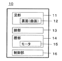
- FIG. 1 is a schematic diagram showing an outline of a lower limb support device 10 according to the first embodiment.
- FIG. 2 is a block diagram illustrating a configuration of the lower limb support device 10 according to the first embodiment.
- FIG. 3 is a block diagram illustrating an example of the configuration of the control unit 16 of the lower limb support brace according to the first embodiment.
- the lower limb support device 10 to which this passive mechanism is applied includes left and right feet 11a and 11b, left and right legs 13a and 13b, a waist 14 and a controller 16.
- the left and right feet 11a and 11b are curved on the back side facing the ground, and each of the user's feet is individually placed on the front side.
- the left and right legs 13a and 13b are connected to the legs of both legs and extend along the vicinity of the legs of the user.
- the waist part 14 is provided in the vicinity of the user's waist, and supports the left and right leg parts 13a and 13b to be individually rotatable, and the left and right motors 15a for rotating the left and right leg parts 13a and 13b forward and backward, respectively. , 15b.
- the control unit 16 captures the ground along the curved surface of the back surface of one foot part, and at the time of kicking out the other leg part opposite to the one leg part connected to the one foot part, Alternatively, the normal rotation and reverse rotation of the motors 15a and 15b of the waist 14 are controlled so as to be reversed when swinging. Thereby, while reducing the burden on the user, a passive walking mechanism that alternately captures the ground along the curved surfaces of the back surfaces 12a and 12b of the left and right feet 11a and 11b and the back of the left and right feet 11a and 11b. Walking can be realized.
- walking by the passive walking mechanism is performed with a natural gait by controlling the kicking and swinging of the legs 13a and 13b only by controlling the forward and reverse rotations of the motors 15a and 15b of the waist 14. It means walking.
- the ground is alternately captured along the curved surfaces of the back surfaces 12a and 12b of the left and right feet 11a and 11b, and the ground is alternately captured by the back of the left and right feet 11a and 11b.
- the actuator since the actuator is not provided in the knee, the overall weight can be reduced as compared with the case where the actuator is provided in each of the knee and the waist. Furthermore, since no actuator is provided at the knee, the power consumption can be suppressed, and the battery usable time can be extended.
- FIG. 4 is a schematic diagram showing various examples of the radius of curvature R of the curved surface of the back surface of the foot portion of FIG.
- the curved surface 12a, the radius of curvature R of 12b, for example, the foot portion 11 (11a, 11b) from the center of gravity 30 in use may be the distance R 1 below to the back 12 of the.
- the curvature radius R, foot 11 (11a, 11b) from a user of the ankle 32 may be a distance R 2 or more to the back surface 12 of the.
- the radius of curvature R is, for example, the distance R 3 from the knee 18 to the back surface 12 (12a, 12b) of the foot 11 (11a, 11b), the leg 13 (13a, 13b), and the waist 14
- the distance R 4 from the connecting portion to the back surface 12 (12a, 12b) of the foot 11 (11a, 11b) may be used. Note that, as shown in FIG. 4, the thickness of the back surface 12 of the foot portion 11 changes corresponding to the radius of curvature R.
- rest is mounted on the surface side of the leg parts 11a and 11b.
- the surface side may be appropriately shaped or the like suitable for placing a foot.
- the left and right leg portions 13a and 13b are connected at both ends to the respective foot portions 11a and 11b and the waist portion 14 of both feet. Further, the leg portions 13a and 13b extend along the vicinity of each of both legs of the user. Further, the legs 13a and 13b can bend the lower legs 17a and 17b on the foot side, the upper legs 19a and 19b on the waist side, the lower legs 17a and 17b, and the upper legs 19a and 19b. You may have the knee parts 18a and 18b to connect.
- the knee portions 18a and 18b may be provided with a reverse rotation prevention mechanism (not shown) that prevents the lower leg portions 17a and 17b from rotating forward with the knee portion 18 as a center. Accordingly, the lower limb support device 10 can be prevented from falling into a knee reversal state that cannot be realized by the user's knee, and can be used safely.
- the waist part 14 is provided in the vicinity of the user's waist, and supports the left and right leg parts 13a and 13b to be individually rotatable. Further, the waist portion 14 has left and right motors 15a and 15b for rotating the left and right leg portions 13a and 13b in the normal direction and the reverse direction, respectively.
- the motors 15a and 15b may be motors capable of normal rotation and reverse rotation.
- the control unit 16 captures the ground along the curved surface of the back surface 12a (12b) of the one foot part 11a (11b), and connects one leg part 13a (13b) to the one foot part 11a (11b).
- the forward rotation and the reverse rotation of the motor 15b (15a) of the waist portion 14 are controlled so that the other leg 13b (13a) on the opposite side of the leg 14 rotates forward when it is kicked, or reverses when it is swung.
- FIG. 5A is a walking image of the user wearing the lower limb support brace 10 according to the first embodiment.
- FIG. 5B is a schematic diagram showing the forward and reverse control states of the right foot motor 15a corresponding to the walking image of FIG.
- This walking image is an image representing a normal gait of the user or a gait desired by the user. That is, the walking image in FIG. 5A is a walking image that serves as an index for obtaining a gait to be obtained while assisting walking with the lower limb support device 10 according to Embodiment 1 to reduce the burden on the user.
- FIG. 5A shows a walking image on a flat ground, but is not limited to this, and may be a walking image when moving up and down a hill.
- the lower back portion 14 includes only motors 15 a and 15 b that rotate the leg portions 13 a and 13 b in the normal direction or the reverse direction, and the knee portion 18 does not include an actuator. Therefore, active control cannot be performed from the knee down.
- the walking image of FIG. 5 (a) it is considered that the lower part from the knee part is not positioned forward than the knee part. Even if it is below the knee due to the inertial force, it can be positioned forward or backward from the knee. This makes it possible to approach a natural walk.
- walking image of FIG. 5A will be described.
- the left foot side kicks out as an axial foot, grounds the heel of the foot 11a on the right foot side, which is a free leg, and the axial foot is on the right foot side.
- the sole of the foot 11a on the right foot side that is the shaft foot is grounded. In this case, it is grounded from the heel to the sole.
- the leg 13b on the left foot side that has become a free leg is swung forward.
- the leg part on the right foot side which is an axial foot is kicked backward.
- the toe of the foot portion 11a on the right foot side leaves the floor, and the right foot side becomes a free foot.
- the heel of the foot 11b on the left foot side is grounded, and the shaft foot is on the left foot side.
- the leg 13a on the right foot side that has become a free leg is swung forward.
- the heel of the foot 11a on the right foot side which is a free leg, is grounded.
- the leg 13a on the right foot side rotates clockwise and kicks the ground backward.
- the control unit 16 controls the motor 15a to rotate forward.
- the leg portion 13a on the right foot side reverses counterclockwise, and the motor 15a is controlled to reverse by the controller 16 so that the leg portion 13a is swung forward.
- the user can easily move the right foot along the forward and reverse rotations of the motor 15a, and the burden can be reduced.
- the forward rotation and reverse rotation of the motor 15a may be controlled according to the walking image of FIG. Or you may switch forward rotation and reverse rotation of the motor 15a at a fixed timing.
- the ground is moved along the curved surfaces of the back surfaces 12a and 12b of the left and right feet 11a and 11b.
- Walking with a passive walking mechanism that alternately captures the ground on the back can be realized. If the ground is caught along the curved surfaces of the back surfaces 12a and 12b of the left and right feet 11a and 11b, walking can be performed smoothly.
- walking when the ground is grounded along the curved surfaces of the back surfaces 12a and 12b when making contact with the back surfaces 12a and 12b of the left and right feet 11a and 11b, walking can be performed more smoothly. This makes it easier to obtain the effect of passive walking.
- an actuator is not provided in the knee, and thus it is possible to reduce the weight and is useful as a use for a lower limb support device for walking assistance that can realize power saving. .
Landscapes
- Health & Medical Sciences (AREA)
- Epidemiology (AREA)
- Pain & Pain Management (AREA)
- Physical Education & Sports Medicine (AREA)
- Rehabilitation Therapy (AREA)
- Life Sciences & Earth Sciences (AREA)
- Animal Behavior & Ethology (AREA)
- General Health & Medical Sciences (AREA)
- Public Health (AREA)
- Veterinary Medicine (AREA)
- Rehabilitation Tools (AREA)
- Toys (AREA)
Abstract
Description
前記両足のそれぞれの足部と接続され、使用者の両脚のそれぞれの近傍に沿って延びる左右の脚部と、
使用者の腰の近傍に設けられ、前記左右の脚部をそれぞれ個別に回転可能に支持すると共に、前記左右の脚部をそれぞれ正転又は逆転させる左右のモータを有する腰部と、
一方の前記足部の裏面の曲面に沿って地面を捉えながら、前記一方の足部と接続された一方の脚部とは反対側の他方の前記脚部を蹴り出し時には正転させ、振り出し時には逆転させるように前記腰部の前記モータの正転又は逆転を制御する制御部と、
を備え、
前記左右の足部の裏面の曲面に沿って地面を前記左右の足部の裏面で地面を交互に捉える受動歩行機構による歩行を実現する。
本発明者は、下肢支援装具の軽量化を図るため、膝部及び腰部のそれぞれに設けるアクチュエータの一方を省略することを検討した。この場合、膝部と腰部のアクチュエータの機能を考慮すると、腰部のアクチュエータが必須と考えられる。しかし、腰部のアクチュエータのみとした場合、脚部の蹴り出しと振り出しはできても、膝部のアクチュエータを省略したために、膝から下のアクティブな制御ができず、それだけではスムーズに全身を前進又は後退させることは困難なことを見出した。
図1は、実施の形態1に係る下肢支援装具10の概略を示す概略図である。図2は、実施の形態1に係る下肢支援装具10の構成を示すブロック図である。図3は、実施の形態1に係る下肢支援装具の制御部16の構成の一例を示すブロック図である。
左右の足部11a、11bのそれぞれの裏面には地面を捉える曲面12a、12bが設けられている。この裏面12a、12bの曲面に沿って地面を捉えることができるので、歩行イメージを自然なものとすることができる。図4は、図1の足部の裏面の曲面の曲率半径Rの様々な例を示す概略図である。この曲面12a、12bの曲率半径Rは、例えば、使用時の重心30から足部11(11a、11b)の裏面12までの距離R1以下であってもよい。さらに、曲率半径Rは、使用者の足首32から足部11(11a、11b)の裏面12までの距離R2以上であってもよい。また、曲率半径Rは、上記の他、例えば、膝部18から足部11(11a、11b)の裏面12(12a、12b)までの距離R3、脚部13(13a、13b)と腰部14との接続箇所から足部11(11a、11b)の裏面12(12a、12b)までの距離R4であってもよい。なお、図4に示すように、曲率半径Rの大きさに対応して、足部11の裏面12の厚さが変化する。
上記のように、裏面に設ける曲面の曲率半径を使用時の重心から裏面までの距離R1以下の長さを曲率半径Rとすることによって、エネルギー効率を向上させることができる。また、足部11a、11bの表面側には使用者の足を載せる。この場合、表面側は、適宜、足を載せるのに適した形状等にしてもよい。
左右の脚部13a、13bは、両端を両足のそれぞれの足部11a、11bと腰部14とにそれぞれ接続されている。また、脚部13a、13bは、使用者の両脚のそれぞれの近傍に沿って延びている。さらに、脚部13a、13bは、足部側の下部脚部17a、17bと、腰部側の上部脚部19a、19bと、下部脚部17a、17bと上部脚部19a、19bとを屈曲可能に接続する膝部18a、18bと、を有してもよい。また、膝部18a、18bは、下部脚部17a、17bが膝部18を中心として前方に向かう回転を抑止する逆転防止機構(図示せず)を備えてもよい。これによって、この下肢支援装具10が、使用者の膝では実現できない膝の逆転状態に陥らないようにすることができ、安全に使用できる。
腰部14は、使用者の腰の近傍に設けられ、左右の脚部13a、13bをそれぞれ個別に回転可能に支持する。また、腰部14には、左右の脚部13a、13bをそれぞれ正転及び逆転させる左右のモータ15a、15bを有する。モータ15a、15bは、正転及び逆転が可能なモータであればよい。制御部16は、一方の足部11a(11b)の裏面12a(12b)の曲面に沿って地面を捉えながら、その一方の足部11a(11b)と接続された一方の脚部13a(13b)とは反対側の他方の脚部13b(13a)の蹴り出し時には正転、あるいは振り出し時には逆転させるように腰部14のモータ15b(15a)の正転及び逆転を制御する。
また、上記の左右の足部11a、11bの裏面12a、12bで接地する際に、裏面12a、12bの曲面に沿って地面を連続的に捉えるようにすれば、歩行をさらに円滑に行うことができ、受動歩行の効果をより得やすくなる。
なお、左右の足部11a、11bの裏面12a、12bの曲面において、土踏まずに相当する部分のみを接地することにより、間欠接地を行うことも可能である。この場合、歩行の円滑性は劣るものの、上記説明と同様の受動歩行の効果を得ることができる。
あるいは、裏面12a、12bにおいて、一つの曲面ではなく、複数の曲面を設け、各曲面の凸部からなる仮想的な曲面で接地するようにしてもよい。この場合、各曲面の凸部での間欠的な接地を順に行うようにすることで、歩行を円滑に行うことができ、受動歩行の効果も得ることができる。また、各曲面の凸部で点接触によって接地するので地面からの影響を受けにくくすることができる。
11、11a、11b 足部
12、12a、12b 裏面(曲面)
13、13a、13b 脚部
14 腰部
15、15a、15b モータ
16 制御部
17、17a、17b 下部脚部
18、18a、18b 膝部
19、19a、19b 上部脚部
20 サドル
21 CPU
22 メモリ
23 記憶装置
24 入出力装置
30 重心
32 足首
Claims (5)
- 地面と対向する裏面側が曲面であって、表面側に使用者の両足のそれぞれを個別に載せる左右の足部と、
前記両足のそれぞれの足部と接続され、使用者の両脚のそれぞれの近傍に沿って延びる左右の脚部と、
使用者の腰の近傍に設けられ、前記左右の脚部をそれぞれ個別に回転可能に支持すると共に、前記左右の脚部をそれぞれ正転又は逆転させる左右のモータを有する腰部と、
一方の前記足部の裏面の曲面に沿って地面を捉えながら、前記一方の足部と接続された一方の脚部とは反対側の他方の前記脚部を蹴り出し時には正転させ、振り出し時には逆転させるように前記腰部の前記左右のモータの正転又は逆転を制御する制御部と、
を備え、
前記左右の足部の裏面の曲面に沿って地面を前記左右の足部の裏面で地面を交互に捉える受動歩行機構による歩行を実現する下肢支援装具。 - 前記足部の裏面の前記曲面の曲率半径は、使用者の足首から前記足部の前記裏面までの距離以上であって、使用時の重心から前記足部の前記裏面までの距離以下である、請求項1に記載の下肢支援装具。
- 前記制御部は、使用者の歩行イメージに応じて前記左右のモータの正転又は逆転を制御する、請求項1又は2に記載の下肢支援装具。
- 前記脚部は、前記足部側の下部脚部と、前記腰部側の上部脚部と、前記下部脚部と前記上部脚部とを屈曲可能に接続する膝部と、を有する、請求項1から3のいずれか一項に記載の下肢支援装具。
- 前記脚部の前記膝部は、前記下部脚部が前記膝部を中心として前方に向かう回転を抑止する逆転防止機構を備える、請求項4に記載の下肢支援装具。
Priority Applications (4)
| Application Number | Priority Date | Filing Date | Title |
|---|---|---|---|
| EP14879117.1A EP3095429A4 (en) | 2014-01-15 | 2014-10-22 | SUPPORT INSTRUMENT FOR LOWER EXTREMITIES |
| CN201480072524.XA CN105899178A (zh) | 2014-01-15 | 2014-10-22 | 下肢支援工具 |
| US15/111,281 US20160331623A1 (en) | 2014-01-15 | 2014-10-22 | Lower extremity support tool |
| JP2015557587A JPWO2015107577A1 (ja) | 2014-01-15 | 2014-10-22 | 下肢支援装具 |
Applications Claiming Priority (4)
| Application Number | Priority Date | Filing Date | Title |
|---|---|---|---|
| JP2014005182 | 2014-01-15 | ||
| JP2014-005182 | 2014-01-15 | ||
| JP2014-006902 | 2014-01-17 | ||
| JP2014006902 | 2014-01-17 |
Publications (1)
| Publication Number | Publication Date |
|---|---|
| WO2015107577A1 true WO2015107577A1 (ja) | 2015-07-23 |
Family
ID=53542506
Family Applications (1)
| Application Number | Title | Priority Date | Filing Date |
|---|---|---|---|
| PCT/JP2014/005368 Ceased WO2015107577A1 (ja) | 2014-01-15 | 2014-10-22 | 下肢支援装具 |
Country Status (5)
| Country | Link |
|---|---|
| US (1) | US20160331623A1 (ja) |
| EP (1) | EP3095429A4 (ja) |
| JP (1) | JPWO2015107577A1 (ja) |
| CN (1) | CN105899178A (ja) |
| WO (1) | WO2015107577A1 (ja) |
Cited By (2)
| Publication number | Priority date | Publication date | Assignee | Title |
|---|---|---|---|---|
| JP2017035334A (ja) * | 2015-08-11 | 2017-02-16 | 国立大学法人 名古屋工業大学 | 歩行機 |
| US20210015694A1 (en) * | 2019-07-16 | 2021-01-21 | Ecole Polytechnique Federale De Lausanne (Epfl) | Bio-inspired standing balance controller for a full-mobilization exoskeleton |
Families Citing this family (3)
| Publication number | Priority date | Publication date | Assignee | Title |
|---|---|---|---|---|
| CN108309688B (zh) * | 2018-02-02 | 2019-12-06 | 上海理工大学 | 一种用于外骨骼型下肢康复机器人的变刚度柔性驱动器 |
| CN109700643B (zh) * | 2019-02-22 | 2020-04-24 | 武汉理工大学 | 多功能助行机器人 |
| JP7581322B2 (ja) * | 2019-07-26 | 2024-11-12 | 住友重機械工業株式会社 | 人間による床レベルのタスク実行を容易にする下半身支持システム |
Citations (8)
| Publication number | Priority date | Publication date | Assignee | Title |
|---|---|---|---|---|
| JPH04352961A (ja) | 1991-05-31 | 1992-12-08 | Kawasaki Heavy Ind Ltd | 歩行補助装置 |
| JP2000166997A (ja) * | 1998-12-10 | 2000-06-20 | Nsk Ltd | 歩行補助装置 |
| JP2004344305A (ja) | 2003-05-21 | 2004-12-09 | Honda Motor Co Ltd | 歩行補助装置 |
| JP2004344304A (ja) | 2003-05-21 | 2004-12-09 | Honda Motor Co Ltd | 歩行補助装置 |
| JP2004344306A (ja) | 2003-05-21 | 2004-12-09 | Honda Motor Co Ltd | 歩行補助装置 |
| WO2009050838A1 (ja) * | 2007-10-15 | 2009-04-23 | Honda Motor Co., Ltd. | 運動補助装置 |
| JP2011142958A (ja) | 2010-01-12 | 2011-07-28 | Toyota Motor Corp | 歩行補助装置 |
| JP2013236741A (ja) * | 2012-05-15 | 2013-11-28 | Nagoya Institute Of Technology | 片脚式歩行支援機 |
Family Cites Families (11)
| Publication number | Priority date | Publication date | Assignee | Title |
|---|---|---|---|---|
| US1800874A (en) * | 1930-04-30 | 1931-04-14 | Edward S Savage | Self-propelled figure toy |
| FR2262957A1 (en) * | 1974-03-07 | 1975-10-03 | Noel Roger | Paraplegic walking frame assembly - has two sticks with pivoting shoes and saddle |
| JPS63150176A (ja) * | 1986-12-15 | 1988-06-22 | 工業技術院長 | 動的歩行ロボツトの歩行制御方法 |
| US6523281B1 (en) * | 1996-09-26 | 2003-02-25 | Richard Lennihan, Jr. | Footwear for heel strikers |
| US7153242B2 (en) * | 2001-05-24 | 2006-12-26 | Amit Goffer | Gait-locomotor apparatus |
| US20040015112A1 (en) * | 2002-02-14 | 2004-01-22 | Salutterback E. Gerald | Controlled motion ankle walker brace |
| JP4417300B2 (ja) * | 2005-07-13 | 2010-02-17 | 本田技研工業株式会社 | 歩行補助装置 |
| US20100263233A1 (en) * | 2009-04-06 | 2010-10-21 | Northwestern University | Rocker shoes for prescribed ankle motion |
| CN101589983B (zh) * | 2009-06-26 | 2011-05-18 | 北京工业大学 | 穿戴式下肢外骨骼装置 |
| JP2012152869A (ja) * | 2011-01-27 | 2012-08-16 | Shigeo Hirose | ロボット歩行装置 |
| DK3498235T3 (da) * | 2013-03-15 | 2023-11-20 | Djo Llc | Krum sål |
-
2014
- 2014-10-22 WO PCT/JP2014/005368 patent/WO2015107577A1/ja not_active Ceased
- 2014-10-22 US US15/111,281 patent/US20160331623A1/en not_active Abandoned
- 2014-10-22 EP EP14879117.1A patent/EP3095429A4/en not_active Withdrawn
- 2014-10-22 JP JP2015557587A patent/JPWO2015107577A1/ja active Pending
- 2014-10-22 CN CN201480072524.XA patent/CN105899178A/zh active Pending
Patent Citations (8)
| Publication number | Priority date | Publication date | Assignee | Title |
|---|---|---|---|---|
| JPH04352961A (ja) | 1991-05-31 | 1992-12-08 | Kawasaki Heavy Ind Ltd | 歩行補助装置 |
| JP2000166997A (ja) * | 1998-12-10 | 2000-06-20 | Nsk Ltd | 歩行補助装置 |
| JP2004344305A (ja) | 2003-05-21 | 2004-12-09 | Honda Motor Co Ltd | 歩行補助装置 |
| JP2004344304A (ja) | 2003-05-21 | 2004-12-09 | Honda Motor Co Ltd | 歩行補助装置 |
| JP2004344306A (ja) | 2003-05-21 | 2004-12-09 | Honda Motor Co Ltd | 歩行補助装置 |
| WO2009050838A1 (ja) * | 2007-10-15 | 2009-04-23 | Honda Motor Co., Ltd. | 運動補助装置 |
| JP2011142958A (ja) | 2010-01-12 | 2011-07-28 | Toyota Motor Corp | 歩行補助装置 |
| JP2013236741A (ja) * | 2012-05-15 | 2013-11-28 | Nagoya Institute Of Technology | 片脚式歩行支援機 |
Non-Patent Citations (2)
| Title |
|---|
| KAZUHIRO NAKATANI; YASUHIRO SUGIMOTO; KOICHI OSUGA: "Demonstration and Analysis of Qadrupedal Passive Dynamic Walking", ADVANCED ROBOTICS, vol. 23, no. 5, 2009, pages 483 - 501, XP055307666, DOI: doi:10.1163/156855309X420039 |
| See also references of EP3095429A4 * |
Cited By (2)
| Publication number | Priority date | Publication date | Assignee | Title |
|---|---|---|---|---|
| JP2017035334A (ja) * | 2015-08-11 | 2017-02-16 | 国立大学法人 名古屋工業大学 | 歩行機 |
| US20210015694A1 (en) * | 2019-07-16 | 2021-01-21 | Ecole Polytechnique Federale De Lausanne (Epfl) | Bio-inspired standing balance controller for a full-mobilization exoskeleton |
Also Published As
| Publication number | Publication date |
|---|---|
| JPWO2015107577A1 (ja) | 2017-03-23 |
| CN105899178A (zh) | 2016-08-24 |
| EP3095429A1 (en) | 2016-11-23 |
| US20160331623A1 (en) | 2016-11-17 |
| EP3095429A4 (en) | 2016-11-23 |
Similar Documents
| Publication | Publication Date | Title |
|---|---|---|
| JP6728297B2 (ja) | 前方または後方指向の外骨格 | |
| US10426686B2 (en) | Driving module and motion assistance apparatus including the same | |
| WO2015107577A1 (ja) | 下肢支援装具 | |
| JP2013248699A5 (ja) | ||
| JP4736946B2 (ja) | 歩行補助具 | |
| JP6688562B2 (ja) | エネルギを回生する歩行ロボットシステム | |
| JP6120421B2 (ja) | 歩行支援機 | |
| CN110202549A (zh) | 刚柔混合驱动的可穿戴助力外骨骼 | |
| Lim et al. | Development of a lower extremity exoskeleton robot with a quasi-anthropomorphic design approach for load carriage | |
| JP6238223B2 (ja) | 歩行支援装置 | |
| KR101628397B1 (ko) | 착용식 로봇의 어깨관절 구조체 | |
| CN108697568A (zh) | 支撑结构 | |
| KR101486808B1 (ko) | 스프링을 이용한 외력의 적용범위 조절이 가능한 보행 보조장치 | |
| KR101912920B1 (ko) | 착용형 하지 보행 재활 로봇용 발목 모듈 | |
| CN106426116A (zh) | 一种下肢助力外骨骼机构系统 | |
| TW201345677A (zh) | 足式機器人 | |
| CN204698953U (zh) | 一种液压驱动型下肢外骨骼仿生装置 | |
| JP6017267B2 (ja) | 歩行運動補助装置 | |
| JP2013208290A (ja) | 歩行支援装置、及び歩行支援プログラム | |
| JP5968757B2 (ja) | 歩行運動補助装置 | |
| Ye et al. | A novel robotic walker for over-ground gait rehabilitation | |
| KR100654759B1 (ko) | 발가락 기능 구조에 의한 모터 부하 저감과 안정성을 지닌이족 보행 로봇 | |
| JP6083502B2 (ja) | 簡潔構造の人間型足構造 | |
| KR102156837B1 (ko) | 운동 보조 장치 | |
| Wiggin et al. | A passive elastic exoskeleton reduces the metabolic cost of walking using controlled energy storage and release |
Legal Events
| Date | Code | Title | Description |
|---|---|---|---|
| 121 | Ep: the epo has been informed by wipo that ep was designated in this application |
Ref document number: 14879117 Country of ref document: EP Kind code of ref document: A1 |
|
| ENP | Entry into the national phase |
Ref document number: 2015557587 Country of ref document: JP Kind code of ref document: A |
|
| REEP | Request for entry into the european phase |
Ref document number: 2014879117 Country of ref document: EP |
|
| WWE | Wipo information: entry into national phase |
Ref document number: 2014879117 Country of ref document: EP |
|
| WWE | Wipo information: entry into national phase |
Ref document number: 15111281 Country of ref document: US |
|
| NENP | Non-entry into the national phase |
Ref country code: DE |