WO2015107691A1 - 車載変圧器 - Google Patents
車載変圧器 Download PDFInfo
- Publication number
- WO2015107691A1 WO2015107691A1 PCT/JP2014/050951 JP2014050951W WO2015107691A1 WO 2015107691 A1 WO2015107691 A1 WO 2015107691A1 JP 2014050951 W JP2014050951 W JP 2014050951W WO 2015107691 A1 WO2015107691 A1 WO 2015107691A1
- Authority
- WO
- WIPO (PCT)
- Prior art keywords
- iron core
- insulating oil
- main leg
- vehicle
- opening
- Prior art date
- Legal status (The legal status is an assumption and is not a legal conclusion. Google has not performed a legal analysis and makes no representation as to the accuracy of the status listed.)
- Ceased
Links
Images

Classifications
-
- H—ELECTRICITY
- H01—ELECTRIC ELEMENTS
- H01F—MAGNETS; INDUCTANCES; TRANSFORMERS; SELECTION OF MATERIALS FOR THEIR MAGNETIC PROPERTIES
- H01F27/00—Details of transformers or inductances, in general
- H01F27/08—Cooling; Ventilating
- H01F27/10—Liquid cooling
- H01F27/12—Oil cooling
-
- H—ELECTRICITY
- H01—ELECTRIC ELEMENTS
- H01F—MAGNETS; INDUCTANCES; TRANSFORMERS; SELECTION OF MATERIALS FOR THEIR MAGNETIC PROPERTIES
- H01F27/00—Details of transformers or inductances, in general
- H01F27/02—Casings
- H01F27/025—Constructional details relating to cooling
-
- H—ELECTRICITY
- H01—ELECTRIC ELEMENTS
- H01F—MAGNETS; INDUCTANCES; TRANSFORMERS; SELECTION OF MATERIALS FOR THEIR MAGNETIC PROPERTIES
- H01F27/00—Details of transformers or inductances, in general
- H01F27/24—Magnetic cores
-
- H—ELECTRICITY
- H01—ELECTRIC ELEMENTS
- H01F—MAGNETS; INDUCTANCES; TRANSFORMERS; SELECTION OF MATERIALS FOR THEIR MAGNETIC PROPERTIES
- H01F27/00—Details of transformers or inductances, in general
- H01F27/24—Magnetic cores
- H01F27/245—Magnetic cores made from sheets, e.g. grain-oriented
-
- H—ELECTRICITY
- H01—ELECTRIC ELEMENTS
- H01F—MAGNETS; INDUCTANCES; TRANSFORMERS; SELECTION OF MATERIALS FOR THEIR MAGNETIC PROPERTIES
- H01F27/00—Details of transformers or inductances, in general
- H01F27/28—Coils; Windings; Conductive connections
-
- H—ELECTRICITY
- H01—ELECTRIC ELEMENTS
- H01F—MAGNETS; INDUCTANCES; TRANSFORMERS; SELECTION OF MATERIALS FOR THEIR MAGNETIC PROPERTIES
- H01F27/00—Details of transformers or inductances, in general
- H01F27/28—Coils; Windings; Conductive connections
- H01F27/2871—Pancake coils
Definitions
- the present invention relates to a vehicle-mounted transformer, and particularly to a vehicle-mounted oil-filled transformer.
- Patent Document 1 Japanese Utility Model Publication No. 61-88222 is a prior document disclosing a dry self-cooling outer iron type transformer.
- the side end surface of the outer peripheral portion of the iron core exhibits a rectangular wave shape with a plurality of protrusions and depressions that circulate along the circumferential direction of the iron core. ing.
- the present invention has been made in view of the above problems, and an object of the present invention is to provide an in-vehicle transformer that can be reduced in size, weight, and height while increasing capacity.
- the in-vehicle transformer according to the present invention includes a main leg, two side legs positioned in parallel to the main leg and opposite to each other across the main leg, and a direction orthogonal to the main leg.
- An iron core that includes two pairs of connecting portions that extend to connect both ends of the main leg portion and both ends of the side leg portions, and is formed by integrally joining a plurality of laminated steel plates, and wound around the main leg portion Insulating oil flow path for storing the insulating oil that is connected to each of both ends of the wound winding and the iron core in the laminating direction of the steel sheet, and around which the winding is immersed together with the iron core.
- Two covers each having an opening, and two windows connected to the opening through the two windows surrounded by the main leg, the side legs, and a pair of connecting parts from the opening of the one cover And a pump for circulating the insulating oil so as to flow toward the opening of the cover.
- FIG. 3 is a cross-sectional view of the iron core and winding of FIG. 2 as viewed from the direction of arrows III-III.
- FIG. 4 is a cross-sectional view of the in-vehicle transformer of FIG. 1 as viewed from the direction of arrows IV-IV. It is sectional drawing which looked at the vehicle-mounted transformer which concerns on Embodiment 2 of this invention from the same direction as FIG. It is sectional drawing which looked at the vehicle-mounted transformer which concerns on Embodiment 3 of this invention from the same direction as FIG.
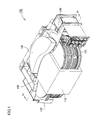
- FIG. 1 is a perspective view showing a configuration of an in-vehicle transformer according to Embodiment 1 of the present invention.
- FIG. 2 is a perspective view showing the configuration of the iron core and windings of the on-vehicle transformer according to the present embodiment.
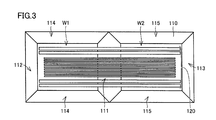
- FIG. 3 is a cross-sectional view of the iron core and windings of FIG. 2 as viewed from the direction of arrows III-III.
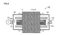
- 4 is a cross-sectional view of the on-vehicle transformer of FIG. 1 as viewed from the direction of arrows IV-IV.
- the on-vehicle transformer according to the first embodiment of the present invention is mounted on a railway vehicle.
- the on-vehicle transformer 100 includes an iron core 110, a winding 120, two covers 130, a conservator 140, and a pump 170.
- the iron core 110 is orthogonal to the main leg 111, two side legs 112, 113 positioned parallel to the main leg 111, and opposite to each other across the main leg 111, and the main leg 111. It includes two pairs of connecting portions 114 and 115 extending in the direction and connecting both ends of the main leg portion 111 and both ends of the side leg portions 112 and 113, respectively.
- one end of the main leg portion 111 and one end of the side leg portion 112 are connected to each other by the connecting portion 114.
- the other end of the main leg 111 and the other end of the side leg 112 are connected to each other by another connecting portion 114.
- a space surrounded by the main leg portion 111, the side leg portion 112, and the pair of connection portions 114 is a window portion W1.
- One end of the main leg portion 111 and one end of the side leg portion 113 are connected to each other by a connecting portion 115.
- the other end of the main leg 111 and the other end of the side leg 113 are connected to each other by another connecting portion 115.
- a space surrounded by the main leg portion 111, the side leg portion 113, and the pair of connection portions 115 is the window portion W2.
- the iron core 110 surrounds the winding 120. That is, the on-vehicle transformer 100 according to the present embodiment is a so-called outer iron type transformer.
- the iron core 110 is integrally formed by joining a plurality of laminated steel plates 11 to each other.
- the surface of the steel plate 11 is coated with an insulating coating by applying an electrically insulating thermosetting resin. After assembling the iron core 110 and the coil 120, the thermosetting resin is cured by heating, so that the steel plates 11 are joined and integrated with each other.
- Winding 120 is wound around the main leg portion 111 of the iron core 110 and is passed through the window portions W1 and W2.
- Winding 120 includes, for example, a plurality of plate-like windings configured by winding a conductor made of copper or the like in the same plane.
- the cover 130 is connected to each of both end faces of the iron core 110 in the stacking direction of the steel plates 11, and stores the insulating oil that surrounds the winding 120 together with the iron core 110 and is immersed in the winding 120.
- Each has an opening 130h serving as a flow path.
- the outer shape of the cover 130 is a rectangular shape smaller than the outer shape of the iron core 110 when viewed in a direction parallel to the stacking direction of the steel plates 11. Therefore, the outer peripheral surface of the iron core 110 is not covered with the cover 130 and is exposed.
- one cover 130 is joined to each of the main leg portion 111, the side leg portions 112 and 113, and the connection portions 114 and 115 by the welded portion 131, and the window portions W1 and W2 are laminated to the steel plate 11. Covering from one side of the direction. In one cover 130, an opening 130 h is provided on the side opposite to the welded part 131 side.
- the other cover 130 is joined to each of the main leg portion 111, the side leg portions 112 and 113, and the connection portions 114 and 115 by the welding portion 131, and the window portions W1 and W2 are connected from the other side in the stacking direction of the steel plates 11. Covering. In the other cover 130, an opening 130h is provided on the opposite side to the welded part 131 side.
- the space defined by the one cover 130, the window portions W1 and W2 of the iron core 110, and the other cover 130 is filled with insulating oil. Therefore, the winding 120 is immersed in insulating oil.
- the opening 130h of one cover 130 and the opening 130h of the other cover 130 are connected by piping with the pump 170 interposed therebetween.
- the pump 170 is disposed outside the space defined by the one cover 130, the window portions W ⁇ b> 1 and W ⁇ b> 2 of the iron core 110, and the other cover 130.
- the pump 170 circulates the insulating oil so as to flow from the opening 130h of the one cover 130 through the windows W1 and W2 toward the opening 130h of the other cover 130.
- the iron core 110 and the winding 120 are cooled by the circulating insulating oil.
- a cooling device (not shown) that cools the insulating oil is provided in the pipe serving as the insulating oil flow path.
- the conservator 140 absorbs the change in the volume of the insulating oil.
- the insulating oil is heated by the heat generation of the iron core 110 and the winding 120, the volume of the insulating oil increases.
- a metal bellows (not shown) of the conservator 140 expands.
- the temperature of insulating oil falls, the volume of insulating oil becomes small. In this case, the metal bellows of the conservator 140 contracts.
- the on-vehicle transformer 100 is configured such that the outer peripheral surface of the iron core 110 is exposed, a tank that accommodates the iron core 110 can be dispensed with. As a result, the external shape of the in-vehicle transformer 100 can be reduced in size and height. Moreover, since the filling amount of insulating oil can be reduced, the vehicle-mounted transformer 100 can be reduced in weight.
- the wind generated by the traveling of the railway vehicle comes into contact with the outer peripheral surface of the iron core 110, whereby the iron core 110 can be air-cooled.
- the cooler of the insulating oil can be reduced in size, and the outer shape of the on-vehicle transformer 100 can be reduced in size.
- the on-vehicle transformer according to the second embodiment of the present invention will be described.
- the vehicle-mounted transformer 100a which concerns on this embodiment differs from the vehicle-mounted transformer 100 which concerns on Embodiment 1 only in the structure of an iron core, description is not repeated about another structure.
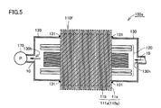
- FIG. 5 is a cross-sectional view of the in-vehicle transformer according to the second embodiment of the present invention viewed from the same direction as FIG.
- fin-shaped irregularities 110f are formed on the outer surface of the iron core 110a in a direction orthogonal to the lamination direction of the steel plates.
- the unevenness 110f is provided over each of the main leg portion 111a, the side leg portions, and the two pairs of connection portions.
- the cross-sectional area of the iron core 110a through which the main magnetic flux passes is the same as that of the iron core 110 according to the first embodiment.
- the unevenness 110f is formed by laminating steel plates 11a and 11b having different lengths. Specifically, the unevenness 110f is configured by alternately laminating long steel plates 11a and short steel plates 11b.
- the cooler can be further downsized as compared with the in-vehicle transformer 100 of the first embodiment, and the outer shape of the in-vehicle transformer 100a can be downsized.
- the on-vehicle transformer according to the third embodiment of the present invention will be described.
- the vehicle-mounted transformer 100b which concerns on this embodiment differs from the vehicle-mounted transformer 100 which concerns on Embodiment 1 only about the structure of an iron core, description is not repeated about another structure.
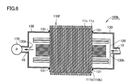
- FIG. 6 is a cross-sectional view of the in-vehicle transformer according to the third embodiment of the present invention as viewed from the same direction as FIG.
- fin-shaped irregularities 110f are formed on the outer surface of the iron core 110b in a direction orthogonal to the laminating direction of the steel plates.
- the unevenness 110f is provided over each of the main leg portion 111b, the side leg portions, and the two pairs of connection portions.
- the cross-sectional area of the iron core 110b through which the main magnetic flux passes is the same as that of the iron core 110 according to the first embodiment.
- the unevenness 110f is formed by laminating the steel plates 11c having the same length alternately at different positions.
- the air cooling effect on the outer peripheral surface of the iron core 110b can be increased.
- the cooler can be further downsized as compared with the in-vehicle transformer 100 of the first embodiment, and the outer shape of the in-vehicle transformer 100b can be downsized.
- the kind of steel plate to be used can be reduced and a number of parts can be reduced.
Landscapes
- Engineering & Computer Science (AREA)
- Power Engineering (AREA)
- Transformer Cooling (AREA)
- Housings And Mounting Of Transformers (AREA)
- Coils Of Transformers For General Uses (AREA)
Abstract
Description
図1は、本発明の実施形態1に係る車載変圧器の構成を示す斜視図である。図2は、本実施形態に係る車載変圧器の鉄心および巻線の構成を示す斜視図である。図3は、図2の鉄心および巻線をIII-III線矢印方向から見た断面図である。図4は、図1の車載変圧器をIV-IV線矢印方向から見た断面図である。本発明の実施形態1に係る車載変圧器は、鉄道車両に搭載される。
図5は、本発明の実施形態2に係る車載変圧器を、図4と同じ方向から見た断面図である。図5に示すように、本発明の実施形態2に係る車載変圧器100aにおいては、鋼板の積層方向に直交する方向にて、鉄心110aの外表面にフィン状の凹凸110fが形成されている。凹凸110fは、主脚部111a、側脚部および2対の接続部の各々に亘って設けられている。なお、主磁束が通過する鉄心110aの断面積は、実施形態1に係る鉄心110と同一である。
図6は、本発明の実施形態3に係る車載変圧器を、図4と同じ方向から見た断面図である。図6に示すように、本発明の実施形態3に係る車載変圧器100bにおいては、鋼板の積層方向に直交する方向にて、鉄心110bの外表面にフィン状の凹凸110fが形成されている。凹凸110fは、主脚部111b、側脚部および2対の接続部の各々に亘って設けられている。なお、主磁束が通過する鉄心110bの断面積は、実施形態1に係る鉄心110と同一である。
Claims (4)
- 主脚部、該主脚部と平行に位置して該主脚部を挟んで互いに反対側に位置する2つの側脚部、および、前記主脚部と直交する方向に延びて前記主脚部の両端と前記側脚部の両端とをそれぞれ繋ぐ2対の接続部とを含み、積層された複数の鋼板が互いに接合されて一体に構成された鉄心と、
前記主脚部に巻き回された巻線と、
前記鋼板の積層方向における前記鉄心の両端面の各々に1つずつ接続され、前記鉄心とともに前記巻線の周囲を囲んで前記巻線が浸漬される絶縁油を貯え、該絶縁油の流路となる開口をそれぞれ有する2つのカバーと、
前記開口に接続され、一方の前記カバーの前記開口から前記主脚部と前記側脚部と1対の前記接続部とによって囲まれた2つの窓部を通過して他方の前記カバーの前記開口に向けて流れるように前記絶縁油を循環させるポンプとを備える、車載変圧器。 - 前記鋼板の積層方向に直交する方向において、前記鉄心の外表面にフィン状の凹凸が形成されている、請求項1に記載の車載変圧器。
- 前記凹凸が互いに長さの異なる前記鋼板を積層することにより形成されている、請求項2に記載の車載変圧器。
- 前記凹凸が同じ長さの前記鋼板を交互に位置を変えて積層することにより形成されている、請求項2に記載の車載変圧器。
Priority Applications (4)
| Application Number | Priority Date | Filing Date | Title |
|---|---|---|---|
| JP2014538005A JP5730448B1 (ja) | 2014-01-20 | 2014-01-20 | 車載変圧器 |
| EP14878860.7A EP3098821A4 (en) | 2014-01-20 | 2014-01-20 | In-vehicle transformer |
| PCT/JP2014/050951 WO2015107691A1 (ja) | 2014-01-20 | 2014-01-20 | 車載変圧器 |
| US15/029,809 US20160268035A1 (en) | 2014-01-20 | 2014-01-20 | Vehicle-mounted transformer |
Applications Claiming Priority (1)
| Application Number | Priority Date | Filing Date | Title |
|---|---|---|---|
| PCT/JP2014/050951 WO2015107691A1 (ja) | 2014-01-20 | 2014-01-20 | 車載変圧器 |
Publications (1)
| Publication Number | Publication Date |
|---|---|
| WO2015107691A1 true WO2015107691A1 (ja) | 2015-07-23 |
Family
ID=53486816
Family Applications (1)
| Application Number | Title | Priority Date | Filing Date |
|---|---|---|---|
| PCT/JP2014/050951 Ceased WO2015107691A1 (ja) | 2014-01-20 | 2014-01-20 | 車載変圧器 |
Country Status (4)
| Country | Link |
|---|---|
| US (1) | US20160268035A1 (ja) |
| EP (1) | EP3098821A4 (ja) |
| JP (1) | JP5730448B1 (ja) |
| WO (1) | WO2015107691A1 (ja) |
Cited By (1)
| Publication number | Priority date | Publication date | Assignee | Title |
|---|---|---|---|---|
| JP2018133492A (ja) * | 2017-02-16 | 2018-08-23 | ファナック株式会社 | 鉄心部およびコイルを備えたリアクトル、モータ駆動装置、パワーコンディショナおよび機械 |
Families Citing this family (3)
| Publication number | Priority date | Publication date | Assignee | Title |
|---|---|---|---|---|
| JP6499691B2 (ja) * | 2017-03-13 | 2019-04-10 | ファナック株式会社 | リアクトル、モータ駆動装置、パワーコンディショナおよび機械 |
| TWI626668B (zh) * | 2017-10-30 | 2018-06-11 | Transformer structure | |
| CN110062715B (zh) * | 2019-01-11 | 2022-07-15 | 广东美信科技股份有限公司 | 一种新能源汽车用车载变压器及新能源汽车 |
Citations (4)
| Publication number | Priority date | Publication date | Assignee | Title |
|---|---|---|---|---|
| JPS6188222U (ja) | 1984-11-16 | 1986-06-09 | ||
| JPH10163022A (ja) * | 1996-12-03 | 1998-06-19 | Minebea Co Ltd | 放熱面積を拡大した積層組立体 |
| JP2007129817A (ja) * | 2005-11-02 | 2007-05-24 | Toyota Motor Corp | 車両の駆動装置 |
| WO2008007513A1 (en) * | 2006-07-10 | 2008-01-17 | Mitsubishi Electric Corporation | Transformer for vehicles |
Family Cites Families (12)
| Publication number | Priority date | Publication date | Assignee | Title |
|---|---|---|---|---|
| US1331896A (en) * | 1920-02-24 | Transformer | ||
| US1301735A (en) * | 1915-08-27 | 1919-04-22 | Gen Electric | Air-blast transformer. |
| US1580811A (en) * | 1920-10-23 | 1926-04-13 | Gen Electric | Stationary induction apparatus |
| US3210830A (en) * | 1959-01-28 | 1965-10-12 | Gen Electric | Method of forming an e-i magnetic core |
| GB887081A (en) * | 1959-06-05 | 1962-01-17 | Ass Elect Ind | Improvements in and relating to laminated cores |
| JP2853505B2 (ja) * | 1993-03-19 | 1999-02-03 | 三菱電機株式会社 | 静止誘導機器 |
| JPH09134823A (ja) * | 1995-11-07 | 1997-05-20 | Toshiba Corp | 車両用変圧器 |
| JP2001155930A (ja) * | 1999-11-25 | 2001-06-08 | Hitachi Ltd | 変圧器 |
| DE102004021107A1 (de) * | 2004-04-29 | 2005-11-24 | Bosch Rexroth Ag | Flüssigkeitskühlung für Eisenkern und Wicklungspakete |
| CN104867661B (zh) * | 2008-09-03 | 2017-10-31 | 株式会社日立产机系统 | 静态设备用卷绕铁芯、非晶变压器及变压器用线圈绕线架 |
| EP2447961B1 (en) * | 2009-06-23 | 2017-10-25 | Mitsubishi Denki Kabushiki Kaisha | Transformer |
| US8648684B2 (en) * | 2009-12-04 | 2014-02-11 | Mitsubishi Electric Corporation | Voltage transforming apparatus |
-
2014
- 2014-01-20 WO PCT/JP2014/050951 patent/WO2015107691A1/ja not_active Ceased
- 2014-01-20 JP JP2014538005A patent/JP5730448B1/ja not_active Expired - Fee Related
- 2014-01-20 EP EP14878860.7A patent/EP3098821A4/en not_active Withdrawn
- 2014-01-20 US US15/029,809 patent/US20160268035A1/en not_active Abandoned
Patent Citations (4)
| Publication number | Priority date | Publication date | Assignee | Title |
|---|---|---|---|---|
| JPS6188222U (ja) | 1984-11-16 | 1986-06-09 | ||
| JPH10163022A (ja) * | 1996-12-03 | 1998-06-19 | Minebea Co Ltd | 放熱面積を拡大した積層組立体 |
| JP2007129817A (ja) * | 2005-11-02 | 2007-05-24 | Toyota Motor Corp | 車両の駆動装置 |
| WO2008007513A1 (en) * | 2006-07-10 | 2008-01-17 | Mitsubishi Electric Corporation | Transformer for vehicles |
Non-Patent Citations (1)
| Title |
|---|
| See also references of EP3098821A4 * |
Cited By (1)
| Publication number | Priority date | Publication date | Assignee | Title |
|---|---|---|---|---|
| JP2018133492A (ja) * | 2017-02-16 | 2018-08-23 | ファナック株式会社 | 鉄心部およびコイルを備えたリアクトル、モータ駆動装置、パワーコンディショナおよび機械 |
Also Published As
| Publication number | Publication date |
|---|---|
| JPWO2015107691A1 (ja) | 2017-03-23 |
| EP3098821A4 (en) | 2017-09-13 |
| EP3098821A1 (en) | 2016-11-30 |
| US20160268035A1 (en) | 2016-09-15 |
| JP5730448B1 (ja) | 2015-06-10 |
Similar Documents
| Publication | Publication Date | Title |
|---|---|---|
| JP4540733B2 (ja) | 車両用変圧器 | |
| JP5730448B1 (ja) | 車載変圧器 | |
| JPWO2018167947A1 (ja) | トランス | |
| JP5754463B2 (ja) | リアクトル | |
| CN111344821B (zh) | 电力转换装置 | |
| KR101604320B1 (ko) | 소음저감구조를 가진 변압기 | |
| WO2016103439A1 (ja) | 車両用変圧器 | |
| JP2016139699A (ja) | コイル装置 | |
| JP5416078B2 (ja) | 磁気部品および磁気部品の製造方法 | |
| CN107924745A (zh) | 油浸式变压器 | |
| JP2008028290A (ja) | リアクトル装置およびその組立方法 | |
| JP7148356B2 (ja) | コイル | |
| TWI654630B (zh) | Oil-immersed transformer and method for manufacturing the same | |
| JP6064943B2 (ja) | 電子機器 | |
| JP4840319B2 (ja) | コア及びこれを用いたトランス、並びに、スイッチング電源装置 | |
| JP2019083235A (ja) | リアクトル | |
| JP4998381B2 (ja) | リアクトル、およびコンバータ | |
| JP2016127109A (ja) | リアクトルの冷却構造 | |
| JP2019096782A (ja) | 油入変圧器 | |
| JP7117905B2 (ja) | リアクトル | |
| JP5516923B2 (ja) | リアクトル、およびコンバータ | |
| JP6612009B1 (ja) | 静止誘導機器 | |
| JP2013183066A (ja) | コイル装置 | |
| JPWO2017002225A1 (ja) | 変圧器 | |
| KR102363710B1 (ko) | 개선된 열 제거부를 구비한 전기 장치 |
Legal Events
| Date | Code | Title | Description |
|---|---|---|---|
| ENP | Entry into the national phase |
Ref document number: 2014538005 Country of ref document: JP Kind code of ref document: A |
|
| 121 | Ep: the epo has been informed by wipo that ep was designated in this application |
Ref document number: 14878860 Country of ref document: EP Kind code of ref document: A1 |
|
| WWE | Wipo information: entry into national phase |
Ref document number: 15029809 Country of ref document: US |
|
| REEP | Request for entry into the european phase |
Ref document number: 2014878860 Country of ref document: EP |
|
| WWE | Wipo information: entry into national phase |
Ref document number: 2014878860 Country of ref document: EP |
|
| NENP | Non-entry into the national phase |
Ref country code: DE |