WO2015107973A1 - タイヤ - Google Patents
タイヤ Download PDFInfo
- Publication number
- WO2015107973A1 WO2015107973A1 PCT/JP2015/050372 JP2015050372W WO2015107973A1 WO 2015107973 A1 WO2015107973 A1 WO 2015107973A1 JP 2015050372 W JP2015050372 W JP 2015050372W WO 2015107973 A1 WO2015107973 A1 WO 2015107973A1
- Authority
- WO
- WIPO (PCT)
- Prior art keywords
- tire
- groove
- inclined portion
- circumferential
- tread
- Prior art date
- Legal status (The legal status is an assumption and is not a legal conclusion. Google has not performed a legal analysis and makes no representation as to the accuracy of the status listed.)
- Ceased
Links
Images

Classifications
-
- B—PERFORMING OPERATIONS; TRANSPORTING
- B60—VEHICLES IN GENERAL
- B60C—VEHICLE TYRES; TYRE INFLATION; TYRE CHANGING; CONNECTING VALVES TO INFLATABLE ELASTIC BODIES IN GENERAL; DEVICES OR ARRANGEMENTS RELATED TO TYRES
- B60C11/00—Tyre tread bands; Tread patterns; Anti-skid inserts
- B60C11/03—Tread patterns
- B60C11/0327—Tread patterns characterised by special properties of the tread pattern
-
- B—PERFORMING OPERATIONS; TRANSPORTING
- B60—VEHICLES IN GENERAL
- B60C—VEHICLE TYRES; TYRE INFLATION; TYRE CHANGING; CONNECTING VALVES TO INFLATABLE ELASTIC BODIES IN GENERAL; DEVICES OR ARRANGEMENTS RELATED TO TYRES
- B60C11/00—Tyre tread bands; Tread patterns; Anti-skid inserts
- B60C11/03—Tread patterns
- B60C11/0302—Tread patterns directional pattern, i.e. with main rolling direction
-
- B—PERFORMING OPERATIONS; TRANSPORTING
- B60—VEHICLES IN GENERAL
- B60C—VEHICLE TYRES; TYRE INFLATION; TYRE CHANGING; CONNECTING VALVES TO INFLATABLE ELASTIC BODIES IN GENERAL; DEVICES OR ARRANGEMENTS RELATED TO TYRES
- B60C11/00—Tyre tread bands; Tread patterns; Anti-skid inserts
- B60C11/03—Tread patterns
- B60C11/032—Patterns comprising isolated recesses
-
- B—PERFORMING OPERATIONS; TRANSPORTING
- B60—VEHICLES IN GENERAL
- B60C—VEHICLE TYRES; TYRE INFLATION; TYRE CHANGING; CONNECTING VALVES TO INFLATABLE ELASTIC BODIES IN GENERAL; DEVICES OR ARRANGEMENTS RELATED TO TYRES
- B60C11/00—Tyre tread bands; Tread patterns; Anti-skid inserts
- B60C11/03—Tread patterns
- B60C11/13—Tread patterns characterised by the groove cross-section, e.g. for buttressing or preventing stone-trapping
- B60C11/1307—Tread patterns characterised by the groove cross-section, e.g. for buttressing or preventing stone-trapping with special features of the groove walls
- B60C11/1323—Tread patterns characterised by the groove cross-section, e.g. for buttressing or preventing stone-trapping with special features of the groove walls asymmetric
-
- B—PERFORMING OPERATIONS; TRANSPORTING
- B60—VEHICLES IN GENERAL
- B60C—VEHICLE TYRES; TYRE INFLATION; TYRE CHANGING; CONNECTING VALVES TO INFLATABLE ELASTIC BODIES IN GENERAL; DEVICES OR ARRANGEMENTS RELATED TO TYRES
- B60C11/00—Tyre tread bands; Tread patterns; Anti-skid inserts
- B60C11/03—Tread patterns
- B60C11/0327—Tread patterns characterised by special properties of the tread pattern
- B60C2011/0334—Stiffness
-
- B—PERFORMING OPERATIONS; TRANSPORTING
- B60—VEHICLES IN GENERAL
- B60C—VEHICLE TYRES; TYRE INFLATION; TYRE CHANGING; CONNECTING VALVES TO INFLATABLE ELASTIC BODIES IN GENERAL; DEVICES OR ARRANGEMENTS RELATED TO TYRES
- B60C11/00—Tyre tread bands; Tread patterns; Anti-skid inserts
- B60C11/03—Tread patterns
- B60C2011/0337—Tread patterns characterised by particular design features of the pattern
- B60C2011/0339—Grooves
- B60C2011/0341—Circumferential grooves
-
- B—PERFORMING OPERATIONS; TRANSPORTING
- B60—VEHICLES IN GENERAL
- B60C—VEHICLE TYRES; TYRE INFLATION; TYRE CHANGING; CONNECTING VALVES TO INFLATABLE ELASTIC BODIES IN GENERAL; DEVICES OR ARRANGEMENTS RELATED TO TYRES
- B60C11/00—Tyre tread bands; Tread patterns; Anti-skid inserts
- B60C11/03—Tread patterns
- B60C2011/0337—Tread patterns characterised by particular design features of the pattern
- B60C2011/0339—Grooves
- B60C2011/0358—Lateral grooves, i.e. having an angle of 45 to 90 degees to the equatorial plane
- B60C2011/0365—Lateral grooves, i.e. having an angle of 45 to 90 degees to the equatorial plane characterised by width
-
- B—PERFORMING OPERATIONS; TRANSPORTING
- B60—VEHICLES IN GENERAL
- B60C—VEHICLE TYRES; TYRE INFLATION; TYRE CHANGING; CONNECTING VALVES TO INFLATABLE ELASTIC BODIES IN GENERAL; DEVICES OR ARRANGEMENTS RELATED TO TYRES
- B60C11/00—Tyre tread bands; Tread patterns; Anti-skid inserts
- B60C11/03—Tread patterns
- B60C2011/0337—Tread patterns characterised by particular design features of the pattern
- B60C2011/0339—Grooves
- B60C2011/0358—Lateral grooves, i.e. having an angle of 45 to 90 degees to the equatorial plane
- B60C2011/0372—Lateral grooves, i.e. having an angle of 45 to 90 degees to the equatorial plane with particular inclination angles
-
- B—PERFORMING OPERATIONS; TRANSPORTING
- B60—VEHICLES IN GENERAL
- B60C—VEHICLE TYRES; TYRE INFLATION; TYRE CHANGING; CONNECTING VALVES TO INFLATABLE ELASTIC BODIES IN GENERAL; DEVICES OR ARRANGEMENTS RELATED TO TYRES
- B60C11/00—Tyre tread bands; Tread patterns; Anti-skid inserts
- B60C11/03—Tread patterns
- B60C2011/0337—Tread patterns characterised by particular design features of the pattern
- B60C2011/0339—Grooves
- B60C2011/0374—Slant grooves, i.e. having an angle of about 5 to 35 degrees to the equatorial plane
- B60C2011/0376—Slant grooves, i.e. having an angle of about 5 to 35 degrees to the equatorial plane characterised by width
-
- B—PERFORMING OPERATIONS; TRANSPORTING
- B60—VEHICLES IN GENERAL
- B60C—VEHICLE TYRES; TYRE INFLATION; TYRE CHANGING; CONNECTING VALVES TO INFLATABLE ELASTIC BODIES IN GENERAL; DEVICES OR ARRANGEMENTS RELATED TO TYRES
- B60C11/00—Tyre tread bands; Tread patterns; Anti-skid inserts
- B60C11/03—Tread patterns
- B60C2011/0337—Tread patterns characterised by particular design features of the pattern
- B60C2011/0339—Grooves
- B60C2011/0381—Blind or isolated grooves
-
- B—PERFORMING OPERATIONS; TRANSPORTING
- B60—VEHICLES IN GENERAL
- B60C—VEHICLE TYRES; TYRE INFLATION; TYRE CHANGING; CONNECTING VALVES TO INFLATABLE ELASTIC BODIES IN GENERAL; DEVICES OR ARRANGEMENTS RELATED TO TYRES
- B60C11/00—Tyre tread bands; Tread patterns; Anti-skid inserts
- B60C11/03—Tread patterns
- B60C2011/0337—Tread patterns characterised by particular design features of the pattern
- B60C2011/0386—Continuous ribs
- B60C2011/0388—Continuous ribs provided at the equatorial plane
Definitions
- the present invention is formed on the outer side of at least one of a pair of circumferential grooves formed across the tire equator line and a pair of circumferential grooves in the tire width direction in plan view of the tread. And a plurality of lug grooves.
- tread patterns have been proposed as tread patterns that improve drainage performance and grip performance.
- a tire including a plurality of lug grooves extending in the tire width direction from the tread ground contact end toward the circumferential groove has been proposed.
- the plurality of lug grooves include an inclined main groove and an inclined sub groove, and the inclined main groove and the inclined sub groove are alternately provided in the tire circumferential direction.
- the length of the inclined main groove is longer than the length of the inclined sub groove (for example, Patent Document 1).
- an object of the present invention is to provide a tire that can improve the steering stability performance while suppressing a decrease in drainage performance.
- the tire of the present invention extends in the tire circumferential direction in a plan view of the tread, and includes at least a pair of circumferential grooves formed across the tire equator line and a pair of circumferential grooves in the tire width direction.
- a first steeply inclined portion that is continuous with the first gently inclined portion on the tread contact end side, and the inclination angle of the first steeply inclined portion with respect to the tire circumferential direction is the tire circumferential direction.
- the secondary inclined groove does not communicate with the circumferential groove on the tire equator line side and does not reach the tread grounding end and terminates on the tire equator line side.
- the inclination angle is larger than the inclination angle of the second gentle inclination portion with respect to the tire circumferential direction.
- the main inclined groove includes a front contact groove wall provided on the side grounded first in the tire rotation direction and a rear ground groove wall provided on the side grounded later in the tire rotation direction, and the tire diameter
- the inclination of the rear contact groove wall with respect to the direction may be larger than the inclination of the front contact groove wall with respect to the tire radial direction.
- the main inclined groove has an inner end located on the innermost side in the tire width direction, and in the tire width direction, the interval between the inner end and one circumferential groove is the tread ground end.
- the distance may be 2.5% or more and 8.0% or less of the ground contact width.
- a width direction groove extending along the tire width direction is not formed, and a plurality of holes are formed at predetermined intervals in the tire circumferential direction. It may be what has been done.
- the groove width of the main inclined groove located on the tire equator line side may be larger than the groove width of the main inclined groove located on the tread ground contact end side.
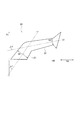
- FIG. 1 is a view showing a tire 100 according to the first embodiment.
- FIG. 2 is a view for explaining the groove width of the main inclined groove 30 according to the first embodiment.
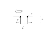
- FIG. 3 is a view for explaining a groove wall of the main inclined groove 30 according to the first embodiment.
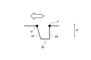
- FIG. 4 is a view for explaining a groove wall of the main inclined groove 30 according to the first embodiment.
- the tire according to the embodiment has a pair of circumferential grooves 20 formed to extend along the tire circumferential direction TC across the tire equator line CL and a pair of circumferential directions in the tire width direction TW in a tread plan view.
- a plurality of lug grooves formed on the outside of at least one circumferential groove 20 of the groove 20.
- the plurality of lug grooves include main inclined grooves 30 and auxiliary inclined grooves 40 that are alternately formed in the tire circumferential direction TC.
- the main inclined groove 30 does not communicate with one circumferential groove 20 on the tire equator line CL side.
- the main inclined groove 30 straddles the tread ground contact end 10E toward the outer side in the tire width direction TW.
- the main inclined groove 30 includes a first gentle slope portion 31 located on the tire equator line CL side and a first steep slope portion 32 located on the tread ground contact end 10E side and continuing to the first gentle slope portion 31. Including.
- the first steeply inclined portion 32 is located on the side farther from the tire equator line CL in the tire width direction TW than the first gently inclined portion 31.
- the first steeply inclined portion 32 is continuous with the first gently inclined portion 31 and straddles the tread ground contact edge 10E toward the outside in the tire width direction TW.
- the inclination angle of the first steeply inclined portion 32 with respect to the tire circumferential direction TC is larger than the inclination angle of the first gently inclined portion 31 with respect to the tire circumferential direction TC.
- the secondary inclined groove 40 does not communicate with one circumferential groove 20 on the tire equator line CL side. Further, the auxiliary inclined groove 40 does not reach the tread ground contact end 10E, but terminates on the tire equator line CL side, that is, on the near side of the tread ground contact end 10E.
- the sub-inclined groove 40 includes a second steeply inclined portion 42 located on the tire equator line CL side, and a second gently inclined portion 41 located on the tread ground contact end 10E side with respect to the second steeply inclined portion 42. .
- the second gently inclined portion 41 is located on the side farther from the tire equator line CL in the tire width direction TW than the second steeply inclined portion 42. As shown in FIG. 1, the second gently inclined portion 41 is not continuous with the second steeply inclined portion 42 and does not straddle the tread ground contact edge 10 ⁇ / b> E toward the outside in the tire width direction TW.
- the inclination angle of the second steeply inclined portion 42 with respect to the tire circumferential direction TC is larger than the inclination angle of the second gently inclined portion 41 with respect to the tire circumferential direction.
- the auxiliary inclined groove 40 does not reach the tread ground contact end 10E and terminates on the tire equator line CL side. As a result, the rigidity of the portion in the vicinity of the tread grounding end 10E is maintained. Therefore, a decrease in the contact area during turning of the vehicle equipped with the tire is suppressed, and a decrease in turning operation stability performance is also suppressed.
- the second inclined portion 42 is located on the tread ground contact end 10E side. Since the sub-gradient groove 40 includes the two gently inclined portions 41, the drainage performance is maintained by the second gently inclined portion 41.
- the pair of circumferential grooves 20 formed with the tire equator line CL interposed therebetween suppresses a decrease in rigidity of a portion including the tire equator line CL, thereby suppressing a decrease in steering initial response performance. Drainage performance can be improved while suppressing a decrease in steering stability performance.
- the main inclined groove 30 since the main inclined groove 30 does not communicate with the circumferential groove 20, a decrease in rigidity of a portion between the inner end 33 of the main inclined groove 30 and the circumferential groove 20 is suppressed, and the turning maneuvering stability is suppressed. A decrease in performance is suppressed.
- the main inclined groove 30 since the main inclined groove 30 straddles the tread ground contact end 10E toward the outside in the tire width direction TW, the main inclined groove 30 can be drained toward the outside in the tire width direction TW.
- the main inclined groove 30 since the main inclined groove 30 includes the first gentle inclined portion 31 located on the tire equator line CL side, the main inclined groove 30 can be efficiently drained along the drainage streamline accompanying the rotation of the tire.
- the main inclined groove 30 when the main inclined groove 30 is entirely constituted by the first gently inclined portion 31, the main inclined groove 30 is easily deformed by the lateral stress generated when the vehicle on which the tire is mounted turns. Includes a first steeply inclined portion 32 continuous with the first gently inclined portion 31 on the tread grounding end 10E side, so that deformation of the main inclined groove 30 (first steeply inclined portion 32) due to lateral stress is suppressed, While maintaining the turning maneuvering stability performance, the drainage performance is improved.
- the plurality of lug grooves include main inclined grooves 30 and auxiliary inclined grooves 40 that are alternately formed in the tire circumferential direction TC. Therefore, compared with the case where all of the lug grooves are constituted by the main inclined grooves 30, a local decrease in rigidity is suppressed.
- the main inclined groove 30 has a first gentle inclined portion 31 and a first steeply inclined portion 32 in order from the tire equator line CL side, and the sub inclined groove 40 is from the tire equator line CL side.
- a second steeply inclined portion 42 and a second gently inclined portion 41 are sequentially provided. Accordingly, there is no portion where the rigidity is locally weak in the tire width direction TW, and the balance of the rigidity of the tread is good, so that stable turning operation stability performance can be obtained.
- FIG. 1 is a view showing a tire 100 according to the first embodiment. Specifically, FIG. 1 is a diagram showing a tread plan view of the tire 100, and shows a tread pattern of the tire 100.
- the tire rotation direction is referred to as a tire circumferential direction TC
- the tread width direction is referred to as a tire width direction TW
- the tire radial direction is referred to as a tire radial direction TR.
- the tire 100 has a pair of circumferential grooves 20, a main inclined groove 30, a sub inclined groove 40, and a plurality of hole portions 50.
- the circumferential groove 20 is a groove extending along the tire circumferential direction TC, and is formed across the tire equator line CL.
- the circumferential groove 20 may be a straight groove having no amplitude in the tire width direction TW when viewed in a cross section in the tire width direction TW, and the circumferential groove 20 is a cross section in the tire width direction TW. When viewed, it may be a zigzag groove having an amplitude in the tire width direction TW.
- a circumferential groove 20A and a circumferential groove 20B are provided as the circumferential groove 20, as the circumferential groove 20, a circumferential groove 20A and a circumferential groove 20B are provided.
- the main inclined groove 30 is a lug groove formed outside the circumferential groove 20 in the tire width direction TW.
- a main inclined groove 30A formed on the outer side of the circumferential groove 20A in the tire width direction TW and a main inclined groove 30B formed on the outer side of the circumferential groove 20B in the tire width direction TW are provided. It has been.
- each main inclined groove 30 does not communicate with the circumferential groove 20 on the tire equator line CL side.
- Each main inclined groove 30 straddles the tread ground contact edge 10E toward the outer side in the tire width direction TW.
- FIG. 1 shows a portion (tread) including a portion in contact with the road surface in a state where the load of the tire 100 is the maximum load load condition and the internal pressure of the tire 100 is the normal internal pressure.
- the pair of tread ground contact ends 10E are both ends of a portion in contact with the road surface in the tire width direction TW in a state where the load of the tire 100 is a maximum load load condition and the internal pressure of the tire 100 is a normal internal pressure.
- the maximum load load condition and the normal internal pressure are as defined in JATMA.
- Each main inclined groove 30 includes a first gently inclined portion 31 located on the tire equator line CL side and a first steeply inclined portion 32 continuous with the first gently inclined portion 31 on the tread ground contact end 10E side.
- the first steeply inclined portion 32 is located on the side farther from the tire equator line CL in the tire width direction TW than the first gently inclined portion 31.
- the first steeply inclined portion 32 is continuous with the first gently inclined portion 31 and straddles the tread ground contact edge 10E toward the outside in the tire width direction TW.
- the inclination angle of the first steeply inclined portion 32 with respect to the tire circumferential direction TC is larger than the inclination angle of the first gently inclined portion 31 with respect to the tire circumferential direction TC.
- the inclination angle of the first gently inclined portion 31 is an angle ⁇ 1 formed by a line connecting the groove centers of the first gently inclined portion 31 (for example, L1 shown in FIG. 2) and the tire circumferential direction TC.
- the inclination angle of the first steeply inclined portion 32 is an angle ⁇ 2 formed by a line (for example, L2 shown in FIG. 2) connecting the groove centers of the first steeply inclined portion 32 and the tire circumferential direction TC.
- the inclination angle of the first gently inclined portion 31 is preferably in the range of 25 ° to 40 °.
- the inclination angle of the first steeply inclined portion 32 is preferably in the range of 60 ° to 80 °. Since the inclination angle of the first steeply inclined portion 32 is in the above-described range, the block rigidity can be kept high even when a large lateral force is applied in the direction from the tire equator line CL to the tread ground contact edge 10E due to cornering or the like. Good steering stability performance can be obtained.
- the main inclined groove 30 has an inner end 33 located on the innermost side in the tire width direction TW.
- the distance d between the inner end 33 (here, the inner end 33A) and the circumferential groove 20 (here, the circumferential groove 20A) is a grounding width D1 (that is, a distance between the tread grounding ends 10E).
- the contact width is preferably 2.5% or more and 8.0% or less of the contact width D1) which is the distance between the tread contact end 10E and the tire equator line CL.
- the distance d is 2.5% or more of the ground contact width D1
- the rigidity of the portion between the main inclined groove 30 and the circumferential groove 20 can be sufficiently improved. It is possible to improve the steering stability performance.
- the distance d is 8.0% or less of the ground contact width D1
- the drainage performance obtained by forming the main inclined groove 30 can be sufficiently obtained.
- the distance d is preferably 3% or more and 5% or less of the ground contact width D1. As a result, it is possible to appropriately achieve both steering stability performance and drainage performance.
- the distance d between the inner end 33B and the circumferential groove 20B is 2.5% or more of the ground contact width D1 in the same manner as the distance d between the inner end 33A and the circumferential groove 20A. It is preferably 0% or less. Furthermore, the distance d is preferably 3% or more and 5% or less of the ground contact width D1.
- the secondary inclined groove 40 is a lug groove formed outside the circumferential groove 20 in the tire width direction TW.
- As the auxiliary inclined groove 40 an auxiliary inclined groove 40A formed outside the circumferential groove 20A in the tire width direction TW and an auxiliary inclined groove 40B formed outside the circumferential groove 20B in the tire width direction TW are provided. It has been.
- each secondary inclined groove 40 does not communicate with the circumferential groove 20 on the tire equator line CL side.
- Each sub-inclined groove 40 does not reach the tread ground contact end 10E side but terminates on the tire equator line CL side, that is, on the near side of the tread ground contact end 10E.
- each sub-inclined groove 40 is formed between the circumferential groove 20 and the tread grounding end 10E.
- Each sub-inclination groove 40 includes a second steeply inclined portion 42 located on the tire equator line CL side, and a second gently inclined portion 41 located on the tread ground contact end 10E side with respect to the second steeply inclined portion 42.
- the second gently inclined portion 41 is located on the side farther from the tire equator line CL in the tire width direction TW than the second steeply inclined portion 42. As shown in FIG. 1, the second gently inclined portion 41 is not continuous with the second steeply inclined portion 42 and does not straddle the tread ground contact edge 10 ⁇ / b> E toward the outside in the tire width direction TW.
- the inclination angle of the second steeply inclined portion 42 with respect to the tire circumferential direction TC is larger than the inclination angle of the second gently inclined portion 41 with respect to the tire circumferential direction TC.
- the inclination angle of the second steeply inclined portion 42 is an angle formed by a line connecting the groove centers of the second steeply inclined portion 42 and the tire circumferential direction TC.
- the inclination angle of the second gently inclined portion 41 is an angle formed by a line connecting the groove centers of the second gently inclined portion 41 and the tire circumferential direction TC.
- the inclination angle of the second steeply inclined portion 42 is preferably in the range of 65 ° to 85 ° with respect to the tire circumferential direction TC. Furthermore, the inclination angle of the second steeply inclined portion 42 is preferably in the range of 70 ° to 80 ° with respect to the tire circumferential direction TC.
- the lateral block rigidity can be kept high when a lateral force such as cornering is generated, and excellent steering stability performance can be obtained.
- the inclination angle of the second gently inclined portion 41 is preferably in the range of 35 ° to 55 ° with respect to the tire circumferential direction TC. Furthermore, the inclination angle of the second gently inclined portion 41 is preferably in the range of 40 ° to 50 ° with respect to the tire circumferential direction TC. When the inclination angle of the second gently inclined portion 41 is in the above-described range, good drainage performance can be obtained.
- the inclination angle of the first gently inclined portion 31 located on the tire equator line CL side is smaller than the inclination angle of the first steeply inclined portion 32 located on the tread ground contact end 10E side.
- the inclination angle of the second steeply inclined portion 42 located on the tire equator line CL side is larger than the inclination angle of the second gently inclined portion 41 located on the tread ground contact end 10E side.
- gently inclined portions and steeply inclined portions are alternately arranged along the tire circumferential direction TC.
- the first gentle slope portion 31 of the main slope groove 30 and the second steep slope portion 42 of the sub slope groove 40 are alternately arranged, and on the tread ground contact end 10E side, the main slope groove.
- the main slope groove. 30 first steeply inclined portions 32 and second gently inclined portions 41 of the sub-inclined grooves 40 are alternately arranged. Accordingly, non-uniformity of drainage performance and non-uniformity of rigidity do not occur, and both drainage performance and steering stability performance can be achieved. It should be noted that the drainage performance improves as the groove inclination angle increases, and that the lateral rigidity increases and the steering stability performance improves as the groove inclination angle decreases.
- the second steeply inclined portion 42 and the second gently inclined portion 41 are preferably discontinuous as shown in FIG. Thereby, the rigidity of the discontinuous portion between the second steeply inclined portion 42 and the second gently inclined portion 41 is improved, and the steering stability performance is improved.
- the second steeply inclined portion 42 and the second gently inclined portion 41 may be continuous.
- the hole 50 is formed between the pair of circumferential grooves 20 and is located at a predetermined interval in the tire circumferential direction TC.
- the predetermined interval is not particularly limited, but is preferably an interval at which 20 to 30 hole portions 50 are provided in one circumference of the tire 100 in the tire circumferential direction TC.
- a width direction groove extending along the tire width direction TW is not provided between the pair of circumferential grooves 20.
- the area of the hole 50 on the surface of the tire 100 is preferably, for example, 1 mm 2 or more and 4 mm 2 or less. When the area of the hole 50 is 1 mm 2 or more, a sufficient heat dissipation effect can be obtained. When the area of the hole 50 is 4 mm 2 or less, a decrease in block rigidity is suppressed, and a deterioration in steering stability performance is suppressed.
- the depth of the hole 50 in the tire radial direction TR is preferably 0.7 mm or more and 5 mm or less. When the depth of the hole 50 is 0.7 mm or more, a sufficient heat dissipation effect can be obtained. When the depth of the hole 50 is 5 mm or less, a decrease in block rigidity is suppressed, and a deterioration in steering stability performance is suppressed.
- FIG. 2 is a view for explaining the groove width of the main inclined groove 30 according to the first embodiment.
- the groove width (here, W1) of the main inclined groove 30 located on the tire circumferential direction TC side is larger than the groove width W2 of the main inclined groove 30 located on the tread ground contact end 10E side.
- the groove width of the main inclined groove 30 is a groove width in a direction orthogonal to a line connecting the groove centers of the main inclined groove 30. Therefore, the groove width W1 is a groove width orthogonal to a line (for example, L1 shown in FIG. 2) connecting the groove centers of the first gently inclined portion 31.
- the groove width W2 is a groove width orthogonal to a line connecting the groove centers of the first steeply inclined portion 32 (for example, L2 shown in FIG. 2).
- the groove width of the main inclined groove 30 may gradually decrease from the tire circumferential direction TC toward the tread ground contact end 10E.
- groove width W2 when the groove width W2 is smaller than the groove width W1, rigidity and a ground contact area against a lateral stress generated when the vehicle on which the tire 100 is mounted are turned are ensured.
- drainage performance improves because groove width W1 is larger than groove width W2.
- FIG. 3 and 4 are views for explaining a groove wall of the main inclined groove 30 according to the first embodiment.
- the main inclined groove 30 includes a front ground groove wall 34 provided on the side grounded first in the tire rotational direction and a rear ground groove wall provided on the side grounded later in the tire rotational direction. 35.
- the position of the front contact groove wall 34 on the surface of the tire 100 is indicated by a point P
- the position of the rear contact groove wall 35 is indicated by a point Q.
- the inclination of the tip contact groove wall 34 with respect to the tire radial direction TR may be the same as the inclination of the rear contact groove wall 35 with respect to the tire radial direction TR (for example, 0 °).
- the inclination of the groove wall of the main inclined groove means an angle formed by the tire radial direction TR and the groove wall.
- the tread that forms the surface of the tire 100 is caused by the force (arrow F shown in FIGS. 3 and 4) that the surface of the tire 100 receives from the ground contact surface at the rear contact end of the main inclined groove 30. A phenomenon of turning up may occur.
- the inclination of the rear contact groove wall 35 with respect to the tire radial direction TR is preferably larger than the inclination of the front contact groove wall 34 with respect to the tire radial direction TR. That is, when the inclination of the front contact groove wall 34 with respect to the tire radial direction TR is 0 °, the surface of the tire 100 (the surface on the side that contacts the ground after the rear contact groove wall 35 in the tire rotation direction) and the rear contact groove The rear contact groove wall 35 is preferably inclined with respect to the tire radial direction TR so that an obtuse angle is formed by the wall 35. A phenomenon in which the tread constituting the surface of the tire 100 is turned up at the rear contact end of the main inclined groove 30 is suppressed.
- the auxiliary inclined groove 40 does not reach the tread ground contact end 10E and terminates on the tire equator line CL side.
- the rigidity of the portion in the vicinity of the tread grounding end 10E is maintained. Therefore, a decrease in the contact area during turning of the vehicle equipped with the tire 100 is suppressed, and a decrease in turning operation stability performance is also suppressed.
- the secondary inclined groove 40 does not reach the tread grounding end 10E and terminates on the tire equator line CL side, the second gentle slope 42 is located on the tread grounding end 10E side with respect to the second steeply inclined portion 42. Since the sub-inclined groove 40 includes the inclined portion 41, the drainage performance is maintained by the second gently inclined portion 41.
- the pair of circumferential grooves 20 formed with the tire equator line CL in between suppresses a decrease in rigidity of a portion including the tire equator line CL, thereby suppressing a decrease in steering initial response performance.
- the drainage performance can be improved while suppressing a decrease in the steering stability performance.
- the main inclined groove 30 since the main inclined groove 30 does not communicate with the circumferential groove 20, a decrease in rigidity of a portion between the inner end of the main inclined groove 30 and the circumferential groove 20 is suppressed, and the turning maneuvering is performed. A decrease in stability performance is suppressed.
- the main inclined groove 30 since the main inclined groove 30 straddles the tread ground contact end 10E toward the outside in the tire width direction TW, the main inclined groove 30 can be drained toward the outside in the tire width direction TW.
- the main inclined groove 30 includes the first gently inclined portion 31 located on the tire equator line CL side, so that the water can be efficiently drained along the drainage streamline accompanying the rotation of the tire 100. it can.
- the entire main inclined groove is configured by the first steeply inclined portion, the main inclined groove 30 is easily deformed by lateral stress generated during turning of the vehicle on which the tire 100 is mounted. Since the tread grounding end 10E side includes the first steeply inclined portion 32 that is continuous with the first gently inclined portion 31, the deformation of the main inclined groove 30 (first steeply inclined portion 32) due to the lateral stress is suppressed, and the turning maneuvering is stabilized. While maintaining the performance, the drainage performance is improved.
- the plurality of lug grooves include main inclined grooves 30 and auxiliary inclined grooves 40 that are alternately formed in the tire circumferential direction TC. Therefore, compared with the case where all of the lug grooves are constituted by the main inclined grooves, a local decrease in rigidity is suppressed.
- the main inclined groove 30 includes a first gentle inclined portion 31 and a first steeply inclined portion 32 in order from the tire equator line CL side, and the sub inclined groove 40 is formed from the tire equator line CL side.
- a second steeply inclined portion 42 and a second gently inclined portion 41 are sequentially provided. Accordingly, there is no portion where the rigidity is locally weak in the tire width direction TW, and the balance of the rigidity of the tread is good, so that stable turning operation stability performance can be obtained.
- the plurality of lug grooves (the main inclined groove 30 and the sub inclined groove 40) formed on both outer sides of the pair of circumferential grooves 20 have been described.
- the plurality of lug grooves (the main inclined groove 30 and the sub inclined groove 40) may be formed outside at least one of the circumferential grooves 20 of the pair of circumferential grooves 20.
- a lug groove different from the main inclined groove 30 and the sub inclined groove 40 may be formed on the outer side of at least one of the pair of circumferential grooves 20.
- the main inclined groove 30 and the auxiliary inclined groove 40 adjacent in the tire circumferential direction TC are opposite to each other in the concave portion of the main inclined groove 30 and the auxiliary inclined groove 40 in a tread plan view. It is preferable that they are arranged as described above. Thereby, the site
Landscapes
- Engineering & Computer Science (AREA)
- Mechanical Engineering (AREA)
- Tires In General (AREA)
Abstract
タイヤ(100)は、主傾斜溝(30)及び副傾斜溝(40)を有する。主傾斜溝(30)は、第1緩傾斜部分(31)及び第1急傾斜部分(32)を有する。副傾斜溝(40)は、第2緩傾斜部分(41)及び第2急傾斜部分(42)を有する。主傾斜溝(30)は、タイヤ赤道線CL側において周方向溝(20)に連通しておらず、タイヤ幅方向TWの外側に向けてトレッド接地端(10E)を跨がっている。副傾斜溝(40)は、タイヤ赤道線CL側において周方向溝(20)に連通しておらず、トレッド接地端(10E)側に到達せずにタイヤ赤道線(CL)側で終端する。
Description
本発明は、トレッド平面視において、タイヤ赤道線を挟んで形成される1対の周方向溝と、タイヤ幅方向において1対の周方向溝の少なくともいずれか一方の周方向溝の外側に形成された複数のラグ溝とを備えるタイヤに関する。
従来、排水性能及びグリップ性能を向上するトレッドパターンとして、様々なトレッドパターンが提案されている。例えば、トレッド平面視において、トレッド接地端から周方向溝に向けて、タイヤ幅方向に沿って延びる複数のラグ溝を備えるタイヤが提案されている。複数のラグ溝は、傾斜主溝及び傾斜副溝を含み、傾斜主溝及び傾斜副溝は、タイヤ周方向において交互に設けられる。タイヤ幅方向において、傾斜主溝の長さは、傾斜副溝の長さよりも長い(例えば、特許文献1)。
しかしながら、上述したタイヤでは、傾斜主溝及び傾斜副溝の双方がトレッド接地端に達しているため、傾斜主溝及び傾斜副溝を有するショルダー部(トレッド接地端の近傍の部位)の剛性が低下してしまう。従って、特に、タイヤが装着された車両の旋回時に接地面積が減少し、ショルダー部の剛性が低下するため、操縦安定性能が低下してしまう。
そこで、本発明は、上述した課題を解決するためになされたものであり、排水性能の低下を抑制しながら、操縦安定性能を向上することを可能とするタイヤを提供することを目的とする。
本発明のタイヤは、トレッド平面視において、タイヤ周方向に沿って延びており、タイヤ赤道線を挟んで形成される1対の周方向溝と、タイヤ幅方向において1対の周方向溝の少なくともいずれか一方の周方向溝の外側に形成された複数のラグ溝とを備えるタイヤであって、複数のラグ溝は、タイヤ周方向において交互に形成された主傾斜溝及び副傾斜溝を含み、主傾斜溝は、タイヤ赤道線の側において周方向溝に連通しておらず、タイヤ幅方向の外側に向けてトレッド接地端を跨がっており、主傾斜溝は、タイヤ赤道線の側に位置する第1緩傾斜部分と、トレッド接地端の側において第1緩傾斜部分に連続する第1急傾斜部分と、を含み、タイヤ周方向に対する第1急傾斜部分の傾斜角は、タイヤ周方向に対する第1緩傾斜部分の傾斜角よりも大きく、副傾斜溝は、タイヤ赤道線の側において周方向溝に連通しておらず、トレッド接地端に到達せずにタイヤ赤道線の側で終端しており、副傾斜溝は、タイヤ赤道線の側に位置する第2急傾斜部分と、第2急傾斜部分に対してトレッド接地端の側に位置する第2緩傾斜部分と、を含み、タイヤ周方向に対する第2急傾斜部分の傾斜角は、タイヤ周方向に対する第2緩傾斜部分の傾斜角よりも大きいことを特徴とする。
本発明のタイヤにおいて、主傾斜溝は、タイヤ回転方向において先に接地する側に設けられる先接地溝壁と、タイヤ回転方向において後に接地する側に設けられる後接地溝壁とを含み、タイヤ径方向に対する後接地溝壁の傾きは、タイヤ径方向に対する先接地溝壁の傾きよりも大きいものであってもよい。
本発明のタイヤにおいて、主傾斜溝は、タイヤ幅方向の最内側に位置する内側端を有しており、タイヤ幅方向において、内側端と一方の周方向溝との間隔は、トレッド接地端の間隔である接地幅の2.5%以上8.0%以下であるものであってもよい。
本発明のタイヤにおいて、1対の周方向溝の間には、タイヤ幅方向に沿って延びる幅方向溝が形成されずに、タイヤ周方向において所定間隔を空けて位置する複数の穴部が形成されているものであってもよい。
本発明のタイヤにおいて、タイヤ赤道線側に位置する主傾斜溝の溝幅は、トレッド接地端側に位置する主傾斜溝の溝幅よりも大きいものであってもよい。
以下において、本発明の実施形態に係るタイヤについて、図面を参照しながら説明する。なお、以下の図面の記載において、同一又は類似の部分には、同一又は類似の符号を付している。
ただし、図面は模式的なものであり、各寸法の比率などは現実のものとは異なることに留意すべきである。従って、具体的な寸法などは以下の説明を参酌して判断すべきである。また、図面相互間においても互いの寸法の関係や比率が異なる部分が含まれていることは勿論である。
[実施形態の概要]
実施形態に係るタイヤは、トレッド平面視において、タイヤ赤道線CLを挟んでタイヤ周方向TCに沿って延びて形成される1対の周方向溝20と、タイヤ幅方向TWにおいて1対の周方向溝20の少なくともいずれか一方の周方向溝20の外側に形成された複数のラグ溝とを備える。複数のラグ溝は、タイヤ周方向TCにおいて交互に形成された主傾斜溝30及び副傾斜溝40を含む。
実施形態に係るタイヤは、トレッド平面視において、タイヤ赤道線CLを挟んでタイヤ周方向TCに沿って延びて形成される1対の周方向溝20と、タイヤ幅方向TWにおいて1対の周方向溝20の少なくともいずれか一方の周方向溝20の外側に形成された複数のラグ溝とを備える。複数のラグ溝は、タイヤ周方向TCにおいて交互に形成された主傾斜溝30及び副傾斜溝40を含む。
主傾斜溝30は、タイヤ赤道線CLの側において一方の周方向溝20に連通していない。また主傾斜溝30は、タイヤ幅方向TWの外側に向けてトレッド接地端10Eを跨がっている。主傾斜溝30は、タイヤ赤道線CLの側に位置する第1緩傾斜部分31と、トレッド接地端10Eの側に位置して第1緩傾斜部分31に連続する第1急傾斜部分32とを含む。
第1急傾斜部分32は、第1緩傾斜部分31よりもタイヤ幅方向TWにおいてタイヤ赤道線CLから離れた側に位置する。第1急傾斜部分32は、第1緩傾斜部分31に連続し、かつ、タイヤ幅方向TWの外側に向けてトレッド接地端10Eを跨がっている。
タイヤ周方向TCに対する第1急傾斜部分32の傾斜角は、タイヤ周方向TCに対する第1緩傾斜部分31の傾斜角よりも大きい。
副傾斜溝40は、タイヤ赤道線CLの側において一方の周方向溝20に連通していない。また副傾斜溝40は、トレッド接地端10Eに到達せずに、タイヤ赤道線CLの側、すなわちトレッド接地端10Eよりも手前の側で終端する。副傾斜溝40は、タイヤ赤道線CLの側に位置する第2急傾斜部分42と、第2急傾斜部分42に対してトレッド接地端10Eの側に位置する第2緩傾斜部分41とを含む。
第2緩傾斜部分41は、第2急傾斜部分42よりもタイヤ幅方向TWにおいてタイヤ赤道線CLから離れた側に位置する。図1に示すように、第2緩傾斜部分41は、第2急傾斜部分42と連続せず、また、タイヤ幅方向TWの外側に向けてトレッド接地端10Eを跨がっていない。
タイヤ周方向TCに対する第2急傾斜部分42の傾斜角は、タイヤ周方向に対する第2緩傾斜部分41の傾斜角よりも大きい。
実施形態では、副傾斜溝40は、トレッド接地端10Eに到達せずにタイヤ赤道線CLの側で終端する。これによって、トレッド接地端10Eの近傍の部位の剛性が維持される。従って、タイヤが装着された車両の旋回時における接地面積の減少が抑制され、旋回操縦安定性能の低下も抑制される。一方で、副傾斜溝40は、トレッド接地端10Eに到達せずにタイヤ赤道線CLの側で終端していても、第2急傾斜部分42に対してトレッド接地端10Eの側に位置する第2緩傾斜部分41を副傾斜溝40が含むため、第2緩傾斜部分41によって排水性能が維持される。
実施形態では、タイヤ赤道線CLを挟んで形成される1対の周方向溝20によって、タイヤ赤道線CLを含む部位の剛性の低下が抑制されるため、操舵初期応答性能の低下が抑制され、操縦安定性能の低下を抑制しながらも、排水性能を向上することができる。
実施形態では、主傾斜溝30は、周方向溝20に連通していないため、主傾斜溝30の内側端33と周方向溝20との間の部位の剛性の低下が抑制され、旋回操縦安定性能の低下が抑制される。一方で、主傾斜溝30は、タイヤ幅方向TWの外側に向けてトレッド接地端10Eを跨がっているため、タイヤ幅方向TWの外側に向けて排水することができる。
実施形態では、主傾斜溝30は、タイヤ赤道線CLの側に位置する第1緩傾斜部分31を含むため、タイヤの回転に伴う排水の流線に沿って効率的に排水することができる。ここで、主傾斜溝30の全体が第1緩傾斜部分31によって構成されていると、タイヤが装着された車両の旋回時に生じる横応力によって主傾斜溝30が変形しやすいが、主傾斜溝30は、トレッド接地端10Eの側において第1緩傾斜部分31に連続する第1急傾斜部分32を含むため、横応力に伴う主傾斜溝30(第1急傾斜部分32)の変形が抑制され、旋回操縦安定性能を維持しながらも、排水性能の向上を図っている。
実施形態では、複数のラグ溝は、タイヤ周方向TCにおいて交互に形成された主傾斜溝30及び副傾斜溝40を含む。従って、ラグ溝の全てが主傾斜溝30によって構成されるケースと比べて、局所的な剛性の低下が抑制される。
実施形態では、主傾斜溝30は、タイヤ赤道線CLの側から順に第1緩傾斜部分31及び第1急傾斜部分32を有しており、副傾斜溝40は、タイヤ赤道線CLの側から順に第2急傾斜部分42及び第2緩傾斜部分41を有している。従って、タイヤ幅方向TWにおいて局所的に剛性が弱い部位が存在せず、トレッドの剛性のバランスがよいため、安定的な旋回操縦安定性能を得ることができる。
[第1実施形態]
(タイヤ)
以下において、第1実施形態に係るタイヤについて説明する。図1は、第1実施形態に係るタイヤ100を示す図である。具体的には、図1は、タイヤ100のトレッド平面視を示す図であり、タイヤ100のトレッドパターンを示している。
(タイヤ)
以下において、第1実施形態に係るタイヤについて説明する。図1は、第1実施形態に係るタイヤ100を示す図である。具体的には、図1は、タイヤ100のトレッド平面視を示す図であり、タイヤ100のトレッドパターンを示している。
タイヤの回転方向について、タイヤ周方向TCと称し、トレッドの幅方向について、タイヤ幅方向TWと称する。また、タイヤ径方向について、タイヤ径方向TRと称する。
図1に示すように、タイヤ100は、1対の周方向溝20と、主傾斜溝30と、副傾斜溝40と、複数の穴部50とを有する。
周方向溝20は、タイヤ周方向TCに沿って延びる溝であり、タイヤ赤道線CLを挟んで形成される。周方向溝20は、タイヤ幅方向TWの断面で見たときに、タイヤ幅方向TWに振幅を有していないストレート溝であってもよく、周方向溝20は、タイヤ幅方向TWの断面で見たときに、タイヤ幅方向TWに振幅を有するジグザグ溝であってもよい。第1実施形態では、周方向溝20として、周方向溝20A及び周方向溝20Bが設けられている。
主傾斜溝30は、タイヤ幅方向TWにおいて周方向溝20の外側に形成されるラグ溝である。主傾斜溝30としては、タイヤ幅方向TWにおいて周方向溝20Aの外側に形成される主傾斜溝30Aと、タイヤ幅方向TWにおいて周方向溝20Bの外側に形成される主傾斜溝30Bとが設けられている。
具体的には、各主傾斜溝30は、タイヤ赤道線CL側において周方向溝20に連通していない。また各主傾斜溝30は、タイヤ幅方向TWの外側に向けてトレッド接地端10Eを跨がっている。
ここで、図1では、タイヤ100の荷重が最大負荷荷重条件であり、タイヤ100の内圧が正規内圧である状態において、路面と接する部位を含む部位(トレッド)が示されている。1対のトレッド接地端10Eは、タイヤ100の荷重が最大負荷荷重条件であり、タイヤ100の内圧が正規内圧である状態において、タイヤ幅方向TWにおいて路面と接する部位の両端である。なお、最大負荷荷重条件及び正規内圧は、JATMAに規定されている通りである。
各主傾斜溝30は、タイヤ赤道線CL側に位置する第1緩傾斜部分31と、トレッド接地端10E側において第1緩傾斜部分31に連続する第1急傾斜部分32とを含む。
第1急傾斜部分32は、第1緩傾斜部分31よりもタイヤ幅方向TWにおいてタイヤ赤道線CLから離れた側に位置する。第1急傾斜部分32は、第1緩傾斜部分31に連続し、かつ、タイヤ幅方向TWの外側に向けてトレッド接地端10Eを跨がっている。
タイヤ周方向TCに対する第1急傾斜部分32の傾斜角は、タイヤ周方向TCに対する第1緩傾斜部分31の傾斜角よりも大きい。
ここで、第1緩傾斜部分31の傾斜角は、第1緩傾斜部分31の溝中心を結ぶ線(例えば、図2に示すL1)とタイヤ周方向TCとによって形成される角度α1である。第1急傾斜部分32の傾斜角は、第1急傾斜部分32の溝中心を結ぶ線(例えば、図2に示すL2)とタイヤ周方向TCとによって形成される角度α2である。
例えば、第1緩傾斜部分31の傾斜角は、25°以上かつ40°以下の範囲であることが好ましい。第1緩傾斜部分31の傾斜角が上述した範囲であることによって、雨天走行時に、接地先着側から後着側に効率的に排水することができる。第1急傾斜部分32の傾斜角は、60°以上80°以下の範囲であることが好ましい。第1急傾斜部分32の傾斜角が上述した範囲であることによって、コーナリングなどでタイヤ赤道線CLからトレッド接地端10Eの方向に大きな横力がかかった状態でも、ブロック剛性を高く保つことができ、良好な操縦安定性能を得ることができる。
第1実施形態において、主傾斜溝30は、タイヤ幅方向TWの最内側に位置する内側端33を有する。タイヤ幅方向TWにおいて、内側端33(ここでは、内側端33A)と周方向溝20(ここでは、周方向溝20A)との間隔dは、トレッド接地端10Eの間隔である接地幅D1(すなわちトレッド接地端10Eとタイヤ赤道線CLとの間隔である接地幅D1)の2.5%以上8.0%以下であることが好ましい。間隔dが接地幅D1の2.5%以上であることによって、主傾斜溝30と周方向溝20との間の部位(タイヤ赤道線CLの近傍の部位)の剛性を十分に向上することができ、操縦安定性能を向上することができる。一方で、間隔dが接地幅D1の8.0%以下であることによって、主傾斜溝30を形成することによって奏する排水性能を十分に得ることができる。さらには、間隔dが接地幅D1の3%以上5%以下であることが好ましい。これによって、操縦安定性能及び排水性能を適切に両立することができる。
なお、タイヤ幅方向TWにおいて、内側端33Bと周方向溝20Bとの間隔dについても、内側端33Aと周方向溝20Aとの間隔dと同様に、接地幅D1の2.5%以上8.0%以下であることが好ましい。さらには、間隔dが接地幅D1の3%以上5%以下であることが好ましい。
副傾斜溝40は、タイヤ幅方向TWにおいて周方向溝20の外側に形成されるラグ溝である。副傾斜溝40としては、タイヤ幅方向TWにおいて周方向溝20Aの外側に形成される副傾斜溝40Aと、タイヤ幅方向TWにおいて周方向溝20Bの外側に形成される副傾斜溝40Bとが設けられている。
具体的には、各副傾斜溝40は、タイヤ赤道線CL側において周方向溝20に連通していない。また各副傾斜溝40は、トレッド接地端10E側に到達せずにタイヤ赤道線CL側、すなわちトレッド接地端10Eよりも手前の側で終端する。言い換えると、各副傾斜溝40は、周方向溝20とトレッド接地端10Eとの間に形成される。
各副傾斜溝40は、タイヤ赤道線CL側に位置する第2急傾斜部分42と、第2急傾斜部分42に対してトレッド接地端10E側に位置する第2緩傾斜部分41とを含む。
第2緩傾斜部分41は、第2急傾斜部分42よりもタイヤ幅方向TWにおいてタイヤ赤道線CLから離れた側に位置する。図1に示すように、第2緩傾斜部分41は、第2急傾斜部分42と連続せず、また、タイヤ幅方向TWの外側に向けてトレッド接地端10Eを跨がっていない。
タイヤ周方向TCに対する第2急傾斜部分42の傾斜角は、タイヤ周方向TCに対する第2緩傾斜部分41の傾斜角よりも大きい。
ここで、第2急傾斜部分42の傾斜角は、第2急傾斜部分42の溝中心を結ぶ線とタイヤ周方向TCとによって形成される角度である。第2緩傾斜部分41の傾斜角は、第2緩傾斜部分41の溝中心を結ぶ線とタイヤ周方向TCとによって形成される角度である。
例えば、第2急傾斜部分42の傾斜角は、タイヤ周方向TCに対して65°以上85°以下の範囲であることが好ましい。さらには、第2急傾斜部分42の傾斜角は、タイヤ周方向TCに対して70°以上80°以下の範囲であることが好ましい。第2急傾斜部分42の傾斜角が上述した範囲であることによって、コーナリングなどの横力発生時に、横方向のブロック剛性を高く保つことができ、優れた操縦安定性能が得られる。
第2緩傾斜部分41の傾斜角は、タイヤ周方向TCに対して35°以上55°以下の範囲であることが好ましい。さらには、第2緩傾斜部分41の傾斜角は、タイヤ周方向TCに対して40°以上かつ50°以下の範囲であることが好ましい。第2緩傾斜部分41の傾斜角が上述した範囲であることによって、良好な排水性能が得られる。
ここで、主傾斜溝30においては、タイヤ赤道線CL側に位置する第1緩傾斜部分31の傾斜角が、トレッド接地端10E側に位置する第1急傾斜部分32の傾斜角よりも小さい。
一方で、副傾斜溝40においては、タイヤ赤道線CL側に位置する第2急傾斜部分42の傾斜角が、トレッド接地端10E側に位置する第2緩傾斜部分41の傾斜角よりも大きい。
このような構成を採用することによって、タイヤ周方向TCに沿って緩傾斜部分及び急傾斜部分が交互に配置される。例えば、タイヤ赤道線CL側においては、主傾斜溝30の第1緩傾斜部分31と副傾斜溝40の第2急傾斜部分42が交互に配置され、トレッド接地端10E側においては、主傾斜溝30の第1急傾斜部分32と副傾斜溝40の第2緩傾斜部分41が交互に配置される。これによって、排水性能の不均一さ及び剛性の不均一さが生じず、排水性能及び操縦安定性能を両立することができる。なお、溝の傾斜角が大きいほど、排水性能が向上し、溝の傾斜角が小さいほど、横方向の剛性が高く、操縦安定性能が向上することに留意すべきである。
第1実施形態において、第2急傾斜部分42及び第2緩傾斜部分41は、図1に示すように、非連続であることが好ましい。これによって、第2急傾斜部分42と第2緩傾斜部分41との間の非連続部分の剛性が向上し、操縦安定性能が向上する。但し、第2急傾斜部分42及び第2緩傾斜部分41は、連続していてもよい。
穴部50は、1対の周方向溝20の間に形成されており、タイヤ周方向TCにおいて所定間隔を空けて位置する。所定間隔は、特に限定されるものではないが、タイヤ周方向TCにおけるタイヤ100の1周において、20~30個の穴部50が設けられる間隔であることが好ましい。ここで、1対の周方向溝20の間には、タイヤ幅方向TWに沿って延びる幅方向溝が設けられていないことに留意すべきである。これによって、タイヤ100が装着された車両の連続走行時において、穴部50によって適切に放熱することが可能である一方で、1対の周方向溝20の間の部位(タイヤ赤道線CLの近傍の部位)の剛性を十分に向上することができ、操縦安定性能を向上することができる。
タイヤ100の表面における穴部50の面積は、例えば、1mm2以上かつ4mm2以下であることが好ましい。穴部50の面積が1mm2以上であることによって、十分な放熱効果が得られる。穴部50の面積が4mm2以下であることによって、ブロック剛性の低下が抑制され、操縦安定性能の悪化が抑制される。タイヤ径方向TRにおける穴部50の深さは、0.7mm以上かつ5mm以下であることが好ましい。穴部50の深さが0.7mm以上であることによって、十分な放熱効果が得られる。穴部50の深さが5mm以下であることによって、ブロック剛性の低下が抑制され、操縦安定性能の悪化が抑制される。
(主傾斜溝の溝幅)
以下において、第1実施形態に係る主傾斜溝の溝幅について説明する。図2は、第1実施形態に係る主傾斜溝30の溝幅を説明するための図である。
以下において、第1実施形態に係る主傾斜溝の溝幅について説明する。図2は、第1実施形態に係る主傾斜溝30の溝幅を説明するための図である。
図2に示すように、タイヤ周方向TC側に位置する主傾斜溝30の溝幅(ここでは、W1)は、トレッド接地端10E側に位置する主傾斜溝30の溝幅W2よりも大きい。
ここで、主傾斜溝30の溝幅は、主傾斜溝30の溝中心を結ぶ線に直交する方向における溝幅である。従って、溝幅W1は、第1緩傾斜部分31の溝中心を結ぶ線(例えば、図2に示すL1)に直交する溝幅である。溝幅W2は、第1急傾斜部分32の溝中心を結ぶ線(例えば、図2に示すL2)に直交する溝幅である。主傾斜溝30の溝幅は、タイヤ周方向TCからトレッド接地端10Eに向けて徐々に小さくなってもよい。
ここで、溝幅W2が溝幅W1よりも小さいことによって、タイヤ100が装着された車両の旋回時に生じる横応力に対する剛性及び接地面積が確保される。一方で、溝幅W1が溝幅W2よりも大きいことによって、排水性能が向上する。
(主傾斜溝の溝壁)
以下において、第1実施形態に係る主傾斜溝の溝壁について説明する。図3及び図4は、第1実施形態に係る主傾斜溝30の溝壁を説明するための図である。
以下において、第1実施形態に係る主傾斜溝の溝壁について説明する。図3及び図4は、第1実施形態に係る主傾斜溝30の溝壁を説明するための図である。
図3及び図4に示すように、主傾斜溝30は、タイヤ回転方向において先に接地する側に設けられる先接地溝壁34と、タイヤ回転方向において後に接地する側に設けられる後接地溝壁35とを含む。図3では、タイヤ100の表面における先接地溝壁34の位置を点P、後接地溝壁35の位置を点Qで示している。
ここで、図3に示すように、タイヤ径方向TRに対する先接地溝壁34の傾きは、タイヤ径方向TRに対する後接地溝壁35の傾きと同じ(例えば、0°)であってもよい。ここで主傾斜溝の溝壁の傾きとは、タイヤ径方向TRと溝壁のなす角を意味する。
しかしながら、このようなケースでは、主傾斜溝30の後接地端において、接地面からタイヤ100の表面が受ける力(図3、図4に示す矢印F)により、タイヤ100の表面を構成するトレッドがめくれ上がる現象が生じる可能性がある。
従って、図4に示すように、タイヤ径方向TRに対する後接地溝壁35の傾きは、タイヤ径方向TRに対する先接地溝壁34の傾きよりも大きいことが好ましい。すなわち、タイヤ径方向TRに対する先接地溝壁34の傾きが0°である場合に、タイヤ100の表面(タイヤ回転方向において、後接地溝壁35よりも後に接地する側の表面)と後接地溝壁35とによって鈍角が形成されるように、後接地溝壁35がタイヤ径方向TRに対して傾いていることが好ましい。主傾斜溝30の後接地端において、タイヤ100の表面を構成するトレッドがめくれ上がる現象が抑制される。
(作用及び効果)
第1実施形態では、副傾斜溝40は、トレッド接地端10Eに到達せずにタイヤ赤道線CL側で終端する。これによって、トレッド接地端10Eの近傍の部位の剛性が維持される。従って、タイヤ100が装着された車両の旋回時における接地面積の減少が抑制され、旋回操縦安定性能の低下も抑制される。一方で、副傾斜溝40は、トレッド接地端10Eに到達せずにタイヤ赤道線CL側で終端していても、第2急傾斜部分42に対してトレッド接地端10E側に位置する第2緩傾斜部分41を副傾斜溝40が含むため、第2緩傾斜部分41によって排水性能が維持される。
第1実施形態では、副傾斜溝40は、トレッド接地端10Eに到達せずにタイヤ赤道線CL側で終端する。これによって、トレッド接地端10Eの近傍の部位の剛性が維持される。従って、タイヤ100が装着された車両の旋回時における接地面積の減少が抑制され、旋回操縦安定性能の低下も抑制される。一方で、副傾斜溝40は、トレッド接地端10Eに到達せずにタイヤ赤道線CL側で終端していても、第2急傾斜部分42に対してトレッド接地端10E側に位置する第2緩傾斜部分41を副傾斜溝40が含むため、第2緩傾斜部分41によって排水性能が維持される。
第1実施形態では、タイヤ赤道線CLを挟んで形成される1対の周方向溝20によって、タイヤ赤道線CLを含む部位の剛性の低下が抑制されるため、操舵初期応答性能の低下が抑制され、操縦安定性能の低下を抑制しながらも、排水性能を向上することができる。
第1実施形態では、主傾斜溝30は、周方向溝20に連通していないため、主傾斜溝30の内側端と周方向溝20との間の部位の剛性の低下が抑制され、旋回操縦安定性能の低下が抑制される。一方で、主傾斜溝30は、タイヤ幅方向TWの外側に向けてトレッド接地端10Eを跨がっているため、タイヤ幅方向TWの外側に向けて排水することができる。
第1実施形態では、主傾斜溝30は、タイヤ赤道線CL側に位置する第1緩傾斜部分31を含むため、タイヤ100の回転に伴う排水の流線に沿って効率的に排水することができる。ここで、主傾斜溝の全体が第1急傾斜部分によって構成されていると、タイヤ100が装着された車両の旋回時に生じる横応力によって主傾斜溝が変形しやすいが、主傾斜溝30は、トレッド接地端10E側において第1緩傾斜部分31に連続する第1急傾斜部分32を含むため、横応力に伴う主傾斜溝30(第1急傾斜部分32)の変形が抑制され、旋回操縦安定性能を維持しながらも、排水性能の向上を図っている。
第1実施形態では、複数のラグ溝は、タイヤ周方向TCにおいて交互に形成された主傾斜溝30及び副傾斜溝40を含む。従って、ラグ溝の全てが主傾斜溝によって構成されるケースと比べて、局所的な剛性の低下が抑制される。
第1実施形態では、主傾斜溝30は、タイヤ赤道線CL側から順に第1緩傾斜部分31及び第1急傾斜部分32を有しており、副傾斜溝40は、タイヤ赤道線CL側から順に第2急傾斜部分42及び第2緩傾斜部分41を有している。従って、タイヤ幅方向TWにおいて局所的に剛性が弱い部位が存在せず、トレッドの剛性のバランスがよいため、安定的な旋回操縦安定性能を得ることができる。
[その他の実施形態]
上述した実施形態では、1対の周方向溝20の両外側に形成された複数のラグ溝(主傾斜溝30及び副傾斜溝40)について説明した。しかしながら、複数のラグ溝(主傾斜溝30及び副傾斜溝40)は、1対の周方向溝20の少なくともいずれか一方の周方向溝20の外側に形成されていればよい。このようなケースにおいて、1対の周方向溝20の少なくともいずれか他方の周方向溝20の外側には、主傾斜溝30及び副傾斜溝40と異なるラグ溝が形成されていてもよい。
上述した実施形態では、1対の周方向溝20の両外側に形成された複数のラグ溝(主傾斜溝30及び副傾斜溝40)について説明した。しかしながら、複数のラグ溝(主傾斜溝30及び副傾斜溝40)は、1対の周方向溝20の少なくともいずれか一方の周方向溝20の外側に形成されていればよい。このようなケースにおいて、1対の周方向溝20の少なくともいずれか他方の周方向溝20の外側には、主傾斜溝30及び副傾斜溝40と異なるラグ溝が形成されていてもよい。
実施形態では特に触れていないが、タイヤ周方向TCにおいて隣接する主傾斜溝30及び副傾斜溝40は、トレッド平面視において主傾斜溝30が有する凹部及び副傾斜溝40が有する凹部が互いに対向するように配置されることが好ましい。これによって、排水性能に寄与する部位及び操縦安定性能に寄与する部位を均一に配置することができる。
以上、本発明の実施形態について説明したが、これらの実施形態は本発明の理解を容易にするために記載された単なる例示に過ぎず、本発明は当該実施形態に限定されるものではない。本発明の技術的範囲は、上記実施形態で開示した具体的な技術事項に限らず、そこから容易に導きうる様々な変形、変更、代替技術なども含むものである。
本出願は、2014年1月15日に出願された日本国特許願第2014-004976号に基づく優先権を主張しており、この出願の全内容が参照により本明細書に組み込まれる。
本発明によれば、排水性能の低下を抑制しながら、操縦安定性能を向上することを可能とするタイヤを提供することができる。
20 周方向溝
30 主傾斜溝
31 第1緩傾斜部分
32 第1急傾斜部分
33 内側端
34 先接地溝壁
35 後接地溝壁
40 副傾斜溝
41 第2緩傾斜部分
42 第2急傾斜部分
50 穴部
100 タイヤ
30 主傾斜溝
31 第1緩傾斜部分
32 第1急傾斜部分
33 内側端
34 先接地溝壁
35 後接地溝壁
40 副傾斜溝
41 第2緩傾斜部分
42 第2急傾斜部分
50 穴部
100 タイヤ
Claims (5)
- トレッド平面視において、タイヤ周方向に沿って延びており、タイヤ赤道線を挟んで形成される1対の周方向溝と、タイヤ幅方向において前記1対の周方向溝の少なくともいずれか一方の周方向溝の外側に形成された複数のラグ溝とを備えるタイヤであって、
複数の前記ラグ溝は、前記タイヤ周方向において交互に形成された主傾斜溝及び副傾斜溝を含み、
前記主傾斜溝は、前記タイヤ赤道線の側において前記周方向溝に連通しておらず、前記タイヤ幅方向の外側に向けてトレッド接地端を跨がっており、
前記主傾斜溝は、前記タイヤ赤道線の側に位置する第1緩傾斜部分と、前記トレッド接地端の側において前記第1緩傾斜部分に連続する第1急傾斜部分と、を含み、
前記タイヤ周方向に対する前記第1急傾斜部分の傾斜角は、前記タイヤ周方向に対する前記第1緩傾斜部分の傾斜角よりも大きく、
前記副傾斜溝は、前記タイヤ赤道線の側において前記周方向溝に連通しておらず、前記トレッド接地端に到達せずに前記タイヤ赤道線の側で終端しており、
前記副傾斜溝は、前記タイヤ赤道線の側に位置する第2急傾斜部分と、前記第2急傾斜部分に対して前記トレッド接地端の側に位置する第2緩傾斜部分と、を含み、
前記タイヤ周方向に対する前記第2急傾斜部分の傾斜角は、前記タイヤ周方向に対する前記第2緩傾斜部分の傾斜角よりも大きいことを特徴とするタイヤ。 - 請求項1に記載のタイヤであって、
前記主傾斜溝は、タイヤ回転方向において先に接地する側に設けられる先接地溝壁と、前記タイヤ回転方向において後に接地する側に設けられる後接地溝壁とを含み、
タイヤ径方向に対する前記後接地溝壁の傾きは、前記タイヤ径方向に対する前記先接地溝壁の傾きよりも大きいこと
を特徴とするタイヤ。 - 請求項1又は2に記載のタイヤであって、
前記主傾斜溝は、前記タイヤ幅方向の最内側に位置する内側端を有しており、
前記タイヤ幅方向において、前記内側端と前記一方の周方向溝との間隔は、前記トレッド接地端の間隔である接地幅の2.5%以上8.0%以下であること
を特徴とするタイヤ。 - 請求項1~3のいずれか一項に記載のタイヤであって、
前記1対の周方向溝の間には、前記タイヤ幅方向に沿って延びる幅方向溝が形成されずに、前記タイヤ周方向において所定間隔を空けて位置する複数の穴部が形成されていること
を特徴とするタイヤ。 - 請求項1~4のいずれか一項に記載のタイヤであって、
前記タイヤ赤道線の側に位置する前記主傾斜溝の溝幅は、前記トレッド接地端の側に位置する前記主傾斜溝の溝幅よりも大きいことを
特徴とするタイヤ。
Priority Applications (2)
| Application Number | Priority Date | Filing Date | Title |
|---|---|---|---|
| EP15737281.4A EP3095620B1 (en) | 2014-01-15 | 2015-01-08 | Tire |
| US15/102,999 US10023012B2 (en) | 2014-01-15 | 2015-01-08 | Tire |
Applications Claiming Priority (2)
| Application Number | Priority Date | Filing Date | Title |
|---|---|---|---|
| JP2014-004976 | 2014-01-15 | ||
| JP2014004976A JP6282865B2 (ja) | 2014-01-15 | 2014-01-15 | タイヤ |
Publications (1)
| Publication Number | Publication Date |
|---|---|
| WO2015107973A1 true WO2015107973A1 (ja) | 2015-07-23 |
Family
ID=53542863
Family Applications (1)
| Application Number | Title | Priority Date | Filing Date |
|---|---|---|---|
| PCT/JP2015/050372 Ceased WO2015107973A1 (ja) | 2014-01-15 | 2015-01-08 | タイヤ |
Country Status (5)
| Country | Link |
|---|---|
| US (1) | US10023012B2 (ja) |
| EP (1) | EP3095620B1 (ja) |
| JP (1) | JP6282865B2 (ja) |
| CN (2) | CN104773036B (ja) |
| WO (1) | WO2015107973A1 (ja) |
Cited By (1)
| Publication number | Priority date | Publication date | Assignee | Title |
|---|---|---|---|---|
| US20180134087A1 (en) * | 2016-11-11 | 2018-05-17 | Sumitomo Rubber Industries, Ltd. | Tire |
Families Citing this family (12)
| Publication number | Priority date | Publication date | Assignee | Title |
|---|---|---|---|---|
| JP6965507B2 (ja) * | 2016-11-11 | 2021-11-10 | 住友ゴム工業株式会社 | タイヤ |
| JP6776827B2 (ja) * | 2016-11-11 | 2020-10-28 | 住友ゴム工業株式会社 | タイヤ |
| JP6911663B2 (ja) * | 2017-09-15 | 2021-07-28 | 住友ゴム工業株式会社 | タイヤ |
| JP6897444B2 (ja) * | 2017-09-15 | 2021-06-30 | 住友ゴム工業株式会社 | タイヤ |
| JP7118625B2 (ja) * | 2017-11-17 | 2022-08-16 | Toyo Tire株式会社 | 空気入りタイヤ |
| JP7176320B2 (ja) * | 2018-09-21 | 2022-11-22 | 住友ゴム工業株式会社 | タイヤ |
| JP7251219B2 (ja) * | 2019-03-05 | 2023-04-04 | 住友ゴム工業株式会社 | タイヤ |
| JP7434795B2 (ja) | 2019-10-11 | 2024-02-21 | 住友ゴム工業株式会社 | タイヤ |
| JP7529971B2 (ja) * | 2020-04-01 | 2024-08-07 | 横浜ゴム株式会社 | タイヤ |
| JP2021000991A (ja) * | 2020-09-24 | 2021-01-07 | 住友ゴム工業株式会社 | タイヤ |
| US12358323B2 (en) * | 2021-11-26 | 2025-07-15 | Sumitomo Rubber Industries, Ltd. | Tire |
| JP2025067214A (ja) * | 2023-10-12 | 2025-04-24 | 住友ゴム工業株式会社 | 自動二輪車用タイヤ |
Citations (3)
| Publication number | Priority date | Publication date | Assignee | Title |
|---|---|---|---|---|
| JP2009101785A (ja) | 2007-10-22 | 2009-05-14 | Sumitomo Rubber Ind Ltd | 空気入りタイヤ |
| JP2009113652A (ja) * | 2007-11-07 | 2009-05-28 | Yokohama Rubber Co Ltd:The | 空気入りタイヤ |
| JP2015020442A (ja) * | 2013-07-16 | 2015-02-02 | 東洋ゴム工業株式会社 | 空気入りタイヤ |
Family Cites Families (9)
| Publication number | Priority date | Publication date | Assignee | Title |
|---|---|---|---|---|
| JP4276614B2 (ja) | 2004-11-25 | 2009-06-10 | 住友ゴム工業株式会社 | 空気入りタイヤ |
| JP5048345B2 (ja) * | 2007-01-10 | 2012-10-17 | 株式会社ブリヂストン | 二輪車用空気入りタイヤ |
| JP4685922B2 (ja) | 2008-12-26 | 2011-05-18 | 住友ゴム工業株式会社 | 空気入りタイヤ |
| CN102574427B (zh) | 2009-07-28 | 2015-04-22 | 倍耐力轮胎股份公司 | 机动车轮胎 |
| JP5478284B2 (ja) | 2010-01-29 | 2014-04-23 | 株式会社ブリヂストン | タイヤ |
| JP5249993B2 (ja) * | 2010-06-18 | 2013-07-31 | 住友ゴム工業株式会社 | 空気入りタイヤ |
| JP5655079B2 (ja) * | 2010-09-09 | 2015-01-14 | 株式会社ブリヂストン | タイヤ |
| JP5337201B2 (ja) | 2011-06-20 | 2013-11-06 | 住友ゴム工業株式会社 | 空気入りタイヤ |
| JP5357988B2 (ja) * | 2012-02-23 | 2013-12-04 | 住友ゴム工業株式会社 | 空気入りタイヤ |
-
2014
- 2014-01-15 JP JP2014004976A patent/JP6282865B2/ja not_active Expired - Fee Related
-
2015
- 2015-01-08 US US15/102,999 patent/US10023012B2/en active Active
- 2015-01-08 WO PCT/JP2015/050372 patent/WO2015107973A1/ja not_active Ceased
- 2015-01-08 EP EP15737281.4A patent/EP3095620B1/en not_active Not-in-force
- 2015-01-14 CN CN201510017171.XA patent/CN104773036B/zh not_active Expired - Fee Related
- 2015-01-14 CN CN201520023531.2U patent/CN204432261U/zh not_active Expired - Lifetime
Patent Citations (3)
| Publication number | Priority date | Publication date | Assignee | Title |
|---|---|---|---|---|
| JP2009101785A (ja) | 2007-10-22 | 2009-05-14 | Sumitomo Rubber Ind Ltd | 空気入りタイヤ |
| JP2009113652A (ja) * | 2007-11-07 | 2009-05-28 | Yokohama Rubber Co Ltd:The | 空気入りタイヤ |
| JP2015020442A (ja) * | 2013-07-16 | 2015-02-02 | 東洋ゴム工業株式会社 | 空気入りタイヤ |
Non-Patent Citations (1)
| Title |
|---|
| See also references of EP3095620A4 |
Cited By (4)
| Publication number | Priority date | Publication date | Assignee | Title |
|---|---|---|---|---|
| US20180134087A1 (en) * | 2016-11-11 | 2018-05-17 | Sumitomo Rubber Industries, Ltd. | Tire |
| CN108068556A (zh) * | 2016-11-11 | 2018-05-25 | 住友橡胶工业株式会社 | 轮胎 |
| US10821780B2 (en) * | 2016-11-11 | 2020-11-03 | Sumitomo Rubber Industries, Ltd. | Tire |
| CN108068556B (zh) * | 2016-11-11 | 2021-05-07 | 住友橡胶工业株式会社 | 轮胎 |
Also Published As
| Publication number | Publication date |
|---|---|
| CN104773036B (zh) | 2017-04-12 |
| EP3095620B1 (en) | 2018-09-12 |
| CN204432261U (zh) | 2015-07-01 |
| JP6282865B2 (ja) | 2018-02-21 |
| EP3095620A4 (en) | 2017-02-22 |
| US20160303918A1 (en) | 2016-10-20 |
| JP2015131603A (ja) | 2015-07-23 |
| CN104773036A (zh) | 2015-07-15 |
| US10023012B2 (en) | 2018-07-17 |
| EP3095620A1 (en) | 2016-11-23 |
Similar Documents
| Publication | Publication Date | Title |
|---|---|---|
| JP6282865B2 (ja) | タイヤ | |
| JP6814638B2 (ja) | 空気入りタイヤ | |
| US9701162B2 (en) | Heavy duty tire | |
| US9096099B2 (en) | Pneumatic tire | |
| JP6194279B2 (ja) | 空気入りタイヤ | |
| JP2017124712A (ja) | タイヤ | |
| JP2016534931A (ja) | 複数のサイプを有するブロックを備えたトレッド | |
| WO2010147076A1 (ja) | 重荷重用タイヤ | |
| JP2008201153A (ja) | 空気入りタイヤ | |
| JP2014141163A (ja) | 不整地走行用の自動二輪車用タイヤ | |
| WO2015133054A1 (ja) | 空気入りタイヤ | |
| JP2010163144A (ja) | 二輪車用タイヤ | |
| JP6434270B2 (ja) | 雪上用空気入りタイヤ | |
| US20180201070A1 (en) | Construction vehicle tire | |
| CN104417279B (zh) | 轮胎 | |
| JP2012030647A (ja) | 空気入りタイヤ | |
| JP6082367B2 (ja) | 空気入りタイヤ | |
| JP7110699B2 (ja) | タイヤ | |
| US10675916B2 (en) | Pneumatic tire | |
| JP2019098950A (ja) | 自動二輪車用タイヤ | |
| JP6055452B2 (ja) | タイヤ | |
| JP6321458B2 (ja) | 空気入りタイヤ | |
| JP4421432B2 (ja) | 空気入りタイヤ | |
| JP2007182147A (ja) | 空気入りタイヤ | |
| JP2006082734A (ja) | 空気入りタイヤ |
Legal Events
| Date | Code | Title | Description |
|---|---|---|---|
| 121 | Ep: the epo has been informed by wipo that ep was designated in this application |
Ref document number: 15737281 Country of ref document: EP Kind code of ref document: A1 |
|
| WWE | Wipo information: entry into national phase |
Ref document number: 15102999 Country of ref document: US |
|
| NENP | Non-entry into the national phase |
Ref country code: DE |
|
| REEP | Request for entry into the european phase |
Ref document number: 2015737281 Country of ref document: EP |
|
| WWE | Wipo information: entry into national phase |
Ref document number: 2015737281 Country of ref document: EP |