WO2015111151A1 - 生産システム - Google Patents
生産システム Download PDFInfo
- Publication number
- WO2015111151A1 WO2015111151A1 PCT/JP2014/051255 JP2014051255W WO2015111151A1 WO 2015111151 A1 WO2015111151 A1 WO 2015111151A1 JP 2014051255 W JP2014051255 W JP 2014051255W WO 2015111151 A1 WO2015111151 A1 WO 2015111151A1
- Authority
- WO
- WIPO (PCT)
- Prior art keywords
- work
- production
- worker
- productivity
- execution
- Prior art date
- Legal status (The legal status is an assumption and is not a legal conclusion. Google has not performed a legal analysis and makes no representation as to the accuracy of the status listed.)
- Ceased
Links
Images






Classifications
-
- G—PHYSICS
- G05—CONTROLLING; REGULATING
- G05B—CONTROL OR REGULATING SYSTEMS IN GENERAL; FUNCTIONAL ELEMENTS OF SUCH SYSTEMS; MONITORING OR TESTING ARRANGEMENTS FOR SUCH SYSTEMS OR ELEMENTS
- G05B15/00—Systems controlled by a computer
- G05B15/02—Systems controlled by a computer electric
-
- G—PHYSICS
- G06—COMPUTING OR CALCULATING; COUNTING
- G06Q—INFORMATION AND COMMUNICATION TECHNOLOGY [ICT] SPECIALLY ADAPTED FOR ADMINISTRATIVE, COMMERCIAL, FINANCIAL, MANAGERIAL OR SUPERVISORY PURPOSES; SYSTEMS OR METHODS SPECIALLY ADAPTED FOR ADMINISTRATIVE, COMMERCIAL, FINANCIAL, MANAGERIAL OR SUPERVISORY PURPOSES, NOT OTHERWISE PROVIDED FOR
- G06Q10/00—Administration; Management
- G06Q10/06—Resources, workflows, human or project management; Enterprise or organisation planning; Enterprise or organisation modelling
-
- G—PHYSICS
- G07—CHECKING-DEVICES
- G07C—TIME OR ATTENDANCE REGISTERS; REGISTERING OR INDICATING THE WORKING OF MACHINES; GENERATING RANDOM NUMBERS; VOTING OR LOTTERY APPARATUS; ARRANGEMENTS, SYSTEMS OR APPARATUS FOR CHECKING NOT PROVIDED FOR ELSEWHERE
- G07C3/00—Registering or indicating the condition or the working of machines or other apparatus, other than vehicles
- G07C3/02—Registering or indicating working or idle time only
- G07C3/04—Registering or indicating working or idle time only using counting means or digital clocks
Definitions
- the present invention relates to a production system that includes a production apparatus and that allows an operator to perform work related to production of the production apparatus.
- Patent Document 1 stores the difficulty level for each recovery work and the skill level for each worker, and in the recovery work when a trouble occurs during production, The necessary skill level is determined, and only the workers with the required skill level or higher are allowed to perform the restoration work. As a result, an operator who is not appropriate for the difficulty level of the recovery work is prevented from performing the recovery work, thereby preventing a reduction in efficiency of the recovery work.
- the production system mentioned above describes the ex-post measures to limit the recovery work after a trouble occurs during production
- the proactive action to limit the execution before the trouble occurs Is not considered.
- the content of the work performed by the worker before the start of production may not be appropriate depending on the experience and ability of the worker, troubles caused by the work will occur repeatedly only by taking action after the fact. There is a risk. In that case, the production efficiency of the production apparatus is lowered, and the productivity may be lowered.
- the main purpose of the production system of the present invention is to suppress a decrease in productivity caused by the work of the worker.
- the production system of the present invention employs the following means in order to achieve the main object described above.
- the production system of the present invention comprises: A production system comprising a production device, wherein an operator can perform work related to production of the production device, Storage means for storing work execution information related to production of the production apparatus by the worker so that the worker can be identified; Detecting means for detecting a decrease in productivity of the production apparatus; When a decrease in productivity of the production apparatus is detected, a specifying unit that identifies an operator who has decreased productivity based on the execution information; Limiting means for limiting the execution of the work related to the production of the production apparatus to the identified worker based on the decrease in productivity; It is a summary to provide.
- the production system according to the present invention can prevent the work related to the production of the production apparatus from being repeatedly performed by the worker who has lowered the productivity, and can suppress the decrease in the productivity.
- FIG. 1 is a configuration diagram showing an outline of the configuration of a mounting system 10.
- FIG. The block diagram which shows the outline of a structure of the mounting apparatus.
- Explanatory drawing which shows an example of the arrangement
- Explanatory drawing which shows an example of the reference image data set by the operator.
- Explanatory drawing which shows an example of the kind of adsorption nozzle 14 set by the operator.
- 7 is a flowchart showing an example of a main processing routine executed by a CPU 81 of the management computer 80.
- 7 is a flowchart illustrating an example of production mode processing executed by a CPU 81 of a management computer 80.
- Explanatory drawing which shows an example of the work authority management information 84b. 7 is a flowchart illustrating an example of work mode processing executed by a CPU 81 of the management computer 80.
- FIG. 1 is a configuration diagram illustrating an outline of the configuration of the mounting system 10
- FIG. 2 is a configuration diagram illustrating an overview of the configuration of the mounting apparatus 11.
- the horizontal direction in FIGS. 1 and 2 is the X-axis direction
- the front-rear direction is the Y-axis direction
- the vertical direction is the Z-axis direction.
- the mounting system 10 performs production management of the entire system such as management of a plurality of mounting devices 11 that perform mounting processing for mounting electronic components (hereinafter referred to as “component P” (see FIG. 2)) on the substrate S, and management of each mounting device 11. And a management computer 80 to perform.
- the mounting process includes a process of placing, mounting, inserting, joining, and bonding the component P on the substrate S.
- the plurality of mounting apparatuses 11 perform the mounting process of the components P while conveying the substrate S from the upstream side (left side in FIG. 1) to the downstream side (right side in FIG. 1) in the X direction. Since it is a structure, it demonstrates without distinguishing especially.
- the mounting apparatus 11 includes a supply unit 12 including a reel and a tray that accommodates a component P, a substrate processing unit 13 that transports and fixes the substrate S, and a plurality of (for example, a component P) (4) suction nozzles 14 are detachably mounted, the mounting head 15 capable of moving the suction nozzle 14 in the Z-axis direction, the head moving mechanism 16 capable of moving the mounting head 15 in the XY direction, and the suction nozzle 14
- a camera unit 17 that photographs the sucked component P, a nozzle stocker 18 that stocks a plurality of types of suction nozzles 14, and a controller 19 that controls the entire apparatus are provided.
- the controller 19 is configured as a microprocessor centered on a CPU, and stores a ROM that stores various processing programs, a RAM that temporarily stores data, and various data necessary for mounting the component P in a rewritable manner.
- An HDD or the like is provided, and the communication with the management computer 80 is possible.
- the mounting head 15 is moved onto the supply unit 12 by the head moving mechanism 16 and sucks components P (for example, four) by each of the plurality of suction nozzles 14, and passes over the camera unit 17 by the head moving mechanism 16. While moving to the substrate S, the components P are sequentially arranged (mounted) on the substrate S based on a predetermined arrangement order.
- components P for example, four
- FIG. 3 is an example of the arrangement order of the parts P set by the worker.
- FIG. 3 shows a case where the arrangement order of the four parts P is set.
- the arrangement order of the parts P it is desirable to set one having a high movement efficiency of the mounting head 15 from a plurality of arrangement orders.
- the operator sets various arrangement orders depending on the experience and ability. For example, as shown in FIG. 3A, the moving distance of the mounting head 15 is short and an efficient arrangement order is set, or as shown in FIG. 3B, the moving distance of the mounting head 15 is long and not efficient. Arrangement order is set.
- the camera unit 17 captures the part P sucked by the suction nozzle 14 when the suction nozzle 14 (mounting head 15) that sucks the part P passes above, and outputs the photographed image to the controller 19.
- the controller 19 compares the captured image with the reference image data to determine whether or not the component P having a different size is attracted or whether the displacement of the attracting position of the component P is within an allowable range. If the controller 19 determines that the suction nozzle 14 is picking up a component P having a different size, or that the positional deviation of the component P is outside the allowable range, the mounting of the component P is stopped and the operator is informed of the suction component. An error (image processing error) is notified.
- the reference image data is set by the operator performing a setting operation on the management computer 80 and stored in advance in the HDD of the controller 19.
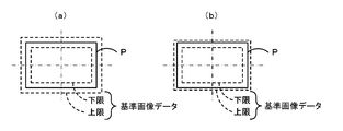
- FIG. 4 is an example of reference image data set by the worker.
- the reference image data for the rectangular component P is set to image data that defines the upper and lower limits of the outer edge of the component P. It is desirable that this reference image data can allow manufacturing errors in the size of the component P, slight positional deviation of the component P, etc. while reliably detecting the size of the component P and the positional displacement of the component P.
- the person sets various reference image data depending on the experience and ability. For example, as shown in FIG.
- appropriate reference image data having a substantially uniform allowable width at the upper limit and lower limit with respect to the outer edge of the component P is set, or as shown in FIG.
- the upper limit allowable width is smaller than the lower limit allowable width, and inappropriate reference image data is set.
- the reference image data as shown in FIG. 4B is set, the outer edge of the part P deviates from the upper limit of the reference image data due to a manufacturing error of the part P or a slight positional deviation. It becomes easy to determine (image processing error).
- the reference image data as shown in FIG. 4A it can be suppressed that the controller 19 determines an unnecessary error as compared with FIG. 4B.
- the allowable range between the upper limit and the lower limit of the reference image data is set too large, an error that the controller 19 should detect cannot be detected.
- the frequency at which the controller 19 determines that an error of the suction component during mounting of the component P varies depending on the setting of the reference image data. For this reason, it can be said that the operation of setting the reference image data of the component P is an operation that affects the productivity of the mounting apparatus 11.
- the work for the operator to set the reference image data is referred to as “work type 2”.
- the nozzle stocker 18 is a box in which a plurality of types of suction nozzles 14 are stocked, and an operator can replace the suction nozzles 14.
- the mounting head 15 is attached with a suction nozzle 14 suitable for mounting the component P among the suction nozzles 14 stocked in the nozzle stocker 18.
- the suction nozzle 14 used for mounting is set by performing a setting operation on the management computer 80 in accordance with the component P on which the worker is mounted.
- the type of the suction nozzle 14 that is set is It is stored in advance in the HDD of the controller 19.
- FIG. 5 is an example of the type of suction nozzle 14 set by the operator.
- the suction nozzle 14 is preferably set to be suitable for the type of the substrate S on which the component P is mounted and the type (size, shape, etc.) of the component P. However, depending on the experience and ability,
- the suction nozzle 14 is set. For example, as shown in FIG.
- the size of the suction portion 14a below the suction nozzle 14 is set to be appropriate for the component P, or below the suction nozzle 14 as shown in FIG. 5B.
- the size of the suction portion 14a is set smaller than that of the component P.
- the suction part 14a is set to be larger than the part P. If the size of the suction part 14a is small, the suction nozzle 14 may not be able to ensure an appropriate suction force. If the size of the suction portion 14a is large, the suction portion 14a may be easily detached from the component P when the suction position of the component P is displaced, and the suction nozzle 14 may not be able to ensure an appropriate suction force.
- the suction nozzle 14 cannot secure an appropriate suction force, an error such as the component P falling during the movement of the mounting head 15 is likely to occur. That is, the frequency at which an error occurs during mounting differs depending on the setting of the type of the suction nozzle 14. For this reason, the operation of setting the type of the suction nozzle 14 used for mounting can be said to be an operation that affects the productivity of the mounting apparatus 11.
- the work for the operator to set the suction nozzle 14 is referred to as “work type 3”.
- the management computer 80 is configured as a microprocessor centered on the CPU 81, and includes a ROM 82 that stores various processing programs, a RAM 83 that temporarily stores data, and an HDD 84 that stores various data in a rewritable manner. In addition, it is configured to be able to communicate with the controller 19 of each mounting apparatus 11.
- an operator needs to log in by entering identification information, and an operator whose identification information has been registered in the HDD 84 can log in.
- the HDD 84 stores work history management information 84a that is information of work performed by the logged-in worker, and work authority management information 84b that is information on the authority of the worker with respect to each work of work types 1 to 3. Details thereof will be described later.
- the management computer 80 can input signals from an input device 86 such as a mouse or a keyboard, and can output various types of information to the display 88.
- FIG. 6 is a flowchart illustrating an example of a main processing routine executed by the CPU 81 of the management computer 80. This routine is executed when a login operation is performed by the operator inputting identification information and a password by operating the input device 86 while a login screen (not shown) is displayed on the display 88.
- the CPU 81 of the management computer 80 first executes a login acceptance process (step S100).
- the login acceptance process the CPU 81 of the management computer 80 performs a process of collating the worker identification information and password stored in the HDD 84 with the worker identification information and password input on the login screen. If the collation results do not match, the management computer 80 performs processing so as to display that fact, and performs processing for prompting the input of the identification information and the password again.
- the CPU 81 of the management computer 80 determines whether the “work” mode in which the worker performs the work types 1 to 3 described above or the “production” mode in which the mounting apparatus 11 performs the board mounting process.
- a selectable mode selection screen is displayed on the display 88 (step S110), and it is determined whether or not the “work” mode is selected (step S120) and whether or not the “production” mode is selected (step S130). To do.
- the operator can also select “Logout” on the mode selection screen.
- the CPU 81 of the management computer 80 performs logout processing such as releasing the login state of the worker and ends the main processing routine.
- step S120 When the CPU 81 of the management computer 80 determines that the “work” mode is selected in step S120, the CPU 81 executes the process in the work mode (step S150), and selects the “production” mode instead of the “work” mode in steps S120 and S130. If it is determined that the process has been performed, the process in the production mode is executed (step S160). When the CPU 81 of the management computer 80 finishes executing the process in each mode, the CPU 81 returns to the process of step S110 again to display the mode selection screen. The following is a detailed description of the production mode processing in step S160.
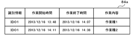
- FIG. 7 is an example of the work history management information 84a.
- the work history management information 84a registers which of the work types 1 to 3 the work content performed during the work mode is associated with the identification information of the worker who performed the work.
- the work history management information 84a registers the work start time and work end time of the worker whose identification information is “ID01” and the work contents (work types 1 and 2) performed by the worker in the work mode process.
- the work history management information 84a may be registered by logout processing. Also, registration of work start time and work end time is not essential.
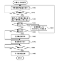
- step S160 The production mode processing in step S160 is performed based on the flowchart shown in FIG.
- the CPU 81 of the management computer 80 first outputs a mounting instruction to each mounting apparatus 11 to perform the board mounting process (step S200) and waits for the board mounting process to be completed (step S200). S210).
- Each mounting apparatus 11 that has received the mounting instruction sequentially executes the process of mounting the component P on the board S.
- the CPU 81 of the management computer 80 executes a productivity analysis process in the completed board mounting process (step S220), and determines whether or not the current productivity has decreased (step S220). Step S230).
- the CPU 81 of the management computer 80 performs the processing of steps S220 and S230 as follows, for example.
- the production efficiency of this time is obtained by dividing the production amount (for example, the number of produced substrates S) by the required production time of the production apparatus 11, and the HDD 84 together with information such as the type of the substrate S and the number of mounted components S. Register with.
- the required production time is the sum of the operation time during which the production apparatus 11 has been operated and the stop time during which the production apparatus 11 has been stopped due to a trouble or the like.
- the CPU 81 of the management computer 80 among the past production efficiencies registered in the HDD 84 in this way, the production efficiencies that are close to the type of the board S on which the mounting process has been performed, the number of mounted components S, and the like. Is extracted and the average value is calculated, and the calculated average value of the past production efficiency is compared with the current production efficiency. If the current production efficiency is below the average value of the past production efficiency, it is determined in step S230 that the productivity has decreased. Note that if the current production efficiency falls below a predetermined ratio (for example, several percent or several tens of percent) or more with respect to the past production efficiency, it may be determined that the productivity has decreased.
- a predetermined ratio for example, several percent or several tens of percent
- the current production efficiency is lower than the previous production efficiency, it may be determined that the productivity has decreased, or the current production efficiency is the standard production efficiency. If it is less than the efficiency, it may be determined that the productivity has decreased.
- the standard production efficiency may be calculated in advance as a theoretical value based on the type of substrate S, the number of mounted components S, and the like.
- step S230 If the CPU 81 of the management computer 80 determines that the productivity is not lowered in step S230, the process in the production mode is terminated as it is. If the CPU 81 of the management computer 80 determines that the productivity has decreased in step S230, the CPU 81 performs the work before the current board mounting process based on the work history management information 84a stored in the HDD 84 in the work mode process. The worker and the work type are identified (step S240). Next, the CPU 81 of the management computer 80 reads the management value P and the warning record for the specified work type of the specified worker from the work authority management information 84b stored in the HDD 84 (step S250).
- FIG. 9 is an example of the work authority management information 84b.
- a management value P As shown in the figure, in the work authority management information 84b, a management value P, a warning record, and an execution limit are registered for each work type 1 to 3 in association with the identification information of the worker.
- the warning result is information on whether or not the worker has been warned about the inadequacy of the work
- the execution restriction is information on whether or not the worker is restricted so as not to perform the work
- the management value P is This is a value used to determine whether or not to issue a warning and whether or not to limit work.
- the warning result is “unwarned” by default
- the execution limit is “no limit” by default.
- the CPU 81 of the management computer 80 performs step In the process of S250, the information of the work types 1 and 2 of the worker whose identification information is “ID01” in the work authority management information 84b of FIG. 9 is read. That is, the CPU 81 of the management computer 80 reads the management value P of the work type 1 value 1 and the warning result of “unwarned”, the management value P of the work type 2 value 0 and the warning result of “unwarned”. .
- the management value P of the work authority management information 84b is updated by incrementing the read management value P by 1 (step S260). As described above, the management value P is incremented by 1 each time the worker decreases the productivity of the mounting apparatus 11, and thus is a value indicating the number of times the worker has decreased the productivity.
- the CPU 81 of the management computer 80 determines whether or not the read warning result is “warned” (step S270). If the CPU 81 of the management computer 80 determines that it is not “warned”, it determines whether or not the management value P is greater than or equal to the first threshold value P1 (step S280).
- the value 2 is set to the first threshold value P1.
- the CPU 81 of the management computer 80 determines that the management value P is greater than or equal to the first threshold value P1, the CPU 81 warns the specified worker that the execution limit for the specified work type is near (step S290), and manages the work authority.
- the warning record in the information 84b is updated to “warned” (step S300), and the production mode process is terminated.
- the warning to the worker is performed, for example, by displaying the identification information and the work type of the worker and the fact that the work execution limit is near on the display 88.
- the CPU 81 of the management computer 80 updates the value 1 of the management value P of the work type 1 read in step S250 to the value 2 in step S260, and sets the value 0 of the management value P of the work type 2 read in step S250.
- the value is updated to 1 in step S260. Therefore, the CPU 81 of the management computer 80 issues a warning for the work type 1 by determining that the management value P of the work type 1 is equal to or higher than the first threshold value P1 in steps S280 and S290.
- the CPU 81 of the management computer 80 determines in step S270 that the management value P is not equal to or greater than the first threshold value P1, the production mode processing ends. For this reason, the CPU 81 of the management computer 80 does not warn the worker when the productivity drop is the first time, but warns the worker when the productivity drop is the second time. Will do.
- the CPU 81 of the management computer 80 determines whether or not the management value P is greater than or equal to the second threshold value P2 (step S310).
- the second threshold value P2 is a value larger than the first threshold value P1, and in the present embodiment, the value 4 is set for the second threshold value P2. If the CPU 81 of the management computer 80 determines in step S310 that the management value P is not greater than or equal to the second threshold value P2, the CPU 81 warns that the execution limit of the specified work type is close to the specified worker (step S320). End production mode processing. Note that the CPU 81 of the management computer 80 performs the process of step S320 in the same manner as the process of step S290.
- step S310 determines in step S310 that the management value P is greater than or equal to the second threshold value P2
- the CPU 81 informs the specified worker that the work of the specified work type is subject to execution restrictions ( In step S330, the execution restriction of the work authority management information 84b is updated to “restricted” (step S340), and the production mode process is terminated.
- the CPU 81 of the management computer 80 warns the operator when the management value P indicating the number of times productivity has decreased reaches the first threshold value P1 (first predetermined number). If the management value P exceeds the first threshold value P1 and reaches the second threshold value P2 (second predetermined number of times), execution restriction is imposed on the worker's work. Further, as in the present embodiment, when the first threshold value P1 and the second threshold value P2 are not continuous values, the management value P exceeds the first threshold value P1 and reaches the second threshold value P2. During this period, the worker is warned. In the work authority management information 84b shown in FIG.
- the worker whose identification information is “ID02” has the management value P of the work type 1 as the value 2 and the management value P of the work type 3 as the value 3. “Warned”. For this reason, if the worker of “ID02” performs the work of work type 1 and decreases the productivity twice, the work of work type 1 is subject to execution restrictions, and the work of work type 3 is performed. If productivity is lowered once, execution of work type 3 is restricted.
- the warnings and execution restrictions are not only displayed on the display 88 of the management computer 80, but are also configured so that the management computer 80 and the computer or portable terminal owned by the manager of the worker can communicate with each other. The restriction may be notified to the administrator's computer or portable terminal.
- FIG. 10 is a diagram illustrating processing in the work mode.
- the CPU 81 of the management computer 80 first displays a work type selection screen for the operator to select a work type on the display 88 (step S400), and the worker selects the work type. It is determined whether or not (step S410).
- the CPU 81 of the management computer 80 determines that the worker has selected the work type, the warning record and execution limit for the work type selected by the logged-in worker based on the work authority management information 84b stored in the HDD 84 are displayed. Is read (step S420), and it is determined whether or not the execution restriction of the work type selected by the operator is “restricted” (step S430).
- the CPU 81 of the management computer 80 determines that there is “restricted”, it displays on the display 88 that the work type selected by the worker cannot be worked due to execution restriction (step S440), and again in step S400. Return to the work selection screen.
- the work type 2 of the worker whose identification information is “ID03” is “restricted”. For this reason, when the worker of “ID03” selects the work type 2, the CPU 81 of the management computer 80 determines that “there is a restriction” and does not perform the work.
- the management value P which is the number of times the productivity has been reduced in the process in the production mode, exceeds the second threshold value P2, the execution restriction is applied. Thereafter, the CPU 81 of the management computer 80 The worker is not allowed to perform the work of the work type. For this reason, this embodiment can suppress that the fall of the productivity of the mounting apparatus 11 is repeated due to the work of the same work type by the same worker.
- Step S450 determines whether or not the warning result of the work type selected by the worker is “warned” (step S450). If the CPU 81 of the management computer 80 determines that it is “warned”, since the execution limit is near, a warning is displayed on the display 88 so as to perform the work while paying attention to the worker (step S460). The work for the selected work type is accepted (step S470).
- Step S ⁇ b> 470 is a step of accepting an input operation such as various setting inputs necessary for the work by the operator operating the input device 86.
- the CPU 81 of the management computer 80 does not accept the operator's input operation when “restricted”, and accepts the operator's input operation when “unrestricted”.
- the CPU 81 of the management computer 80 determines in step S450 that the warning record is not “warned”, the process skips step S460 and accepts the work in step S470.
- the “warned” work type is alerted when the worker performs the work, and thus the worker can be made to perform the work carefully. For this reason, this embodiment can suppress effectively that productivity falls by work of the same work type of the same worker.
- the CPU 81 of the management computer 80 determines whether or not the worker's work has been completed (step S480). If the CPU 81 determines that the work has been completed, the work history management information 84a of the HDD 84 stores the type of work performed this time. Is associated with the worker identification information and registered as a work history (step S490), and the process in the work mode is terminated. In the process of step S490, the CPU 81 of the management computer 80 registers the work history management information 84a illustrated in FIG.
- the mounting system 10 identifies the worker whose productivity has been reduced based on the work history management information 84a when the productivity of the mounting apparatus 11 decreases, and the identified worker produces the product.
- management value P management value
- P2 predetermined number of times
- the mounting system 10 includes an input device 86 that allows an operator to perform an input operation necessary for work on the mounting apparatus 11, and the CPU 81 of the management computer 80 has no execution restriction in the process of step S430 in the work mode process. If it is determined, an input operation to the input device 86 by the worker is accepted to perform the process of step S470, and if it is determined that there is an execution restriction in the process of step S430 of the work mode process, step S470 is performed. Since this process is not performed, the input operation to the input device 86 by the operator is not accepted. For this reason, this embodiment can prevent more reliably that setting work etc. are performed by the worker to whom execution restriction was applied.
- the mounting system 10 can execute a plurality of types of work types 1 to 3 as work related to the production of the mounting apparatus 11, and the management computer 80 stores the worker and the work type in the work history management information 84 a of the HDD 84.
- the CPU 81 of the management computer 80 identifies the worker and the work type whose productivity has been reduced by the production mode process, and restricts the execution to the work type identified by the identified worker. multiply. For this reason, the present embodiment can efficiently limit the execution to a work that is likely to cause a decrease in productivity, so that the worker can appropriately perform without restricting the execution more than necessary. Execution restrictions can be applied.
- the mounting system 10 warns the worker that the execution limit is near before the CPU 81 of the management computer 80 limits the execution, it is possible to cause the worker to perform the work carefully. For this reason, it is possible to give the worker an opportunity for work improvement as compared with the case where execution restriction is imposed without notice.
- the CPU 81 of the management computer 80 counts the number of times that the worker has lowered productivity (management value P), and limits the execution when the counted number reaches a predetermined threshold value P2. Therefore, the process for restricting execution can be simplified.
- the management value P is used for each work type.
- the present invention is not limited to this, and the management value P may not be used for each work type. In this case, one management value P may be used for each worker regardless of the work type.
- the management value P is used without distinguishing a plurality of mounting apparatuses 11 included in the mounting system 10.
- the present invention is not limited to this, and the management value P is used for each mounting apparatus 11. Also good.
- the characteristics of each mounting apparatus 11 may differ if the configuration of a plurality of mounting apparatuses 11 included in the mounting system 10 is different. Therefore, the work performed by the operator on each mounting apparatus 11 varies. May be likely to occur. For this reason, by using the management value P for each mounting apparatus 11, it becomes possible to further suppress the decrease in productivity due to the work of the worker.
- the CPU 81 of the management computer 80 alerts the worker who gave a warning in the process in the work mode.
- the present invention is not limited to this, and the alert may not be performed.
- the processing of S450 and S460 in the work mode processing of FIG. 10 may be omitted.
- the CPU 81 of the management computer 80 issues a warning before restricting execution in the process in the production mode.
- the present invention is not limited to this, and the warning may not be performed.
- the processes in S270 to S300 and S320 in the production mode process in FIG. 8 and the processes in S450 and S460 in the work mode process in FIG. 10 are omitted, and the warning record is not registered in the work authority management information 84b in FIG. It should be.
- the present invention is not limited to this, and any index may be used as long as it can detect a decrease in productivity.
- the management value P is not limited to counting the number of times productivity has decreased, and the pause time may be accumulated.
- a warning is given when the management value P, which is the cumulative pause time, reaches the first threshold value P1 (first predetermined time), and execution is restricted to work when it reaches the second threshold value P2 (second predetermined time). It may be something that applies.
- the management value P for the corresponding work type of the worker who performed the work in the immediately previous work mode process is obtained.
- the present invention is not limited to this, and when a decrease in productivity is detected in the production mode process, the management value P for the corresponding work type of the worker who performed the work before that is read. Good.
- the management value P for the corresponding work type of the worker who performed the work up to a predetermined time before the production start time or the production end time may be read.
- the management value P of the worker who performed the most recent work may be read out for each of a plurality of kinds of work types. In these cases, it is not limited to reading the management value P of one worker, and the management values P of a plurality of workers may be read.
- the present invention is not limited thereto, and the present invention may be applied to a mounting system 10 including only one mounting apparatus 11.
- the present invention may be applied to a mounting system including various apparatuses such as a printing apparatus that prints solder on the substrate P by screen printing.
- the present invention is not limited to the one applied to the mounting system 10 including the mounting device 11 that mounts the component P on the substrate S, but includes a production device, and a production that allows an operator to perform work related to production of the production device. Anything that applies to the system may be used.
- an assembly device that assembles various parts
- an assembly system that enables an operator to perform operations on the assembly device
- a processing device that performs machining of various parts
- It can be applied to various production systems such as a processing system capable of executing the above.
- the present invention can be used not only in the field of mounting technology for mounting components on a substrate but also in the field of production technology.
Landscapes
- Engineering & Computer Science (AREA)
- Business, Economics & Management (AREA)
- General Physics & Mathematics (AREA)
- Physics & Mathematics (AREA)
- Entrepreneurship & Innovation (AREA)
- Strategic Management (AREA)
- Economics (AREA)
- Human Resources & Organizations (AREA)
- Marketing (AREA)
- Development Economics (AREA)
- Operations Research (AREA)
- Quality & Reliability (AREA)
- Tourism & Hospitality (AREA)
- Game Theory and Decision Science (AREA)
- General Business, Economics & Management (AREA)
- Educational Administration (AREA)
- Theoretical Computer Science (AREA)
- General Engineering & Computer Science (AREA)
- Automation & Control Theory (AREA)
- Management, Administration, Business Operations System, And Electronic Commerce (AREA)
- Supply And Installment Of Electrical Components (AREA)
- General Factory Administration (AREA)
Abstract
Description
生産装置を備え、作業者が前記生産装置の生産に関する作業を実行可能な生産システムであって、
作業者による前記生産装置の生産に関する作業の実行情報を、作業者を識別可能に記憶する記憶手段と、
前記生産装置の生産性の低下を検出する検出手段と、
前記生産装置の生産性の低下が検出された場合、前記実行情報に基づいて生産性を低下させた作業者を特定する特定手段と、
生産性の低下に基づいて、前記特定された作業者に対して前記生産装置の生産に関する作業に実行制限をかける制限手段と、
を備えることを要旨とする。
Claims (5)
- 生産装置を備え、作業者が前記生産装置の生産に関する作業を実行可能な生産システムであって、
作業者による前記生産装置の生産に関する作業の実行情報を、作業者を識別可能に記憶する記憶手段と、
前記生産装置の生産性の低下を検出する検出手段と、
前記生産装置の生産性の低下が検出された場合、前記実行情報に基づいて生産性を低下させた作業者を特定する特定手段と、
生産性の低下に基づいて、前記特定された作業者に対して前記生産装置の生産に関する作業に実行制限をかける制限手段と、
を備える生産システム。 - 請求項1に記載の生産システムであって、
作業者が前記生産装置の生産に関する作業に必要な入力操作を行う入力手段を備え、
前記制限手段が作業に実行制限をかけていない場合には、作業者による前記入力手段への入力操作を受け付け、前記制限手段が作業に実行制限をかけている場合には、作業者による前記入力手段への入力操作を受け付けない
生産システム。 - 請求項1または2に記載の生産システムであって、
前記生産装置の生産に関する作業として、複数種の作業が実行可能であり、
前記記憶手段は、前記実行情報を作業者と作業種とを識別可能に記憶し、
前記特定手段は、生産性を低下させた作業者と作業種とを特定し、
前記制限手段は、前記特定された作業者の前記特定された作業種に対して実行制限をかける
生産システム。 - 請求項1ないし3いずれか1項に記載の生産システムであって、
前記制限手段が実行制限をかける前に、前記特定された作業者に対して警告を行う警告手段を備える
生産システム。 - 請求項1ないし4いずれか1項に記載の生産システムであって、
前記制限手段は、前記特定された作業者が生産性を低下させた回数をカウントし、該カウントした回数が所定回数に到達したときに実行制限をかける
生産システム。
Priority Applications (5)
| Application Number | Priority Date | Filing Date | Title |
|---|---|---|---|
| EP14879893.7A EP3098679A4 (en) | 2014-01-22 | 2014-01-22 | Production system |
| US15/111,555 US10216159B2 (en) | 2014-01-22 | 2014-01-22 | Production system |
| CN201480073781.5A CN106415418B (zh) | 2014-01-22 | 2014-01-22 | 生产系统 |
| PCT/JP2014/051255 WO2015111151A1 (ja) | 2014-01-22 | 2014-01-22 | 生産システム |
| JP2015558633A JP6319813B2 (ja) | 2014-01-22 | 2014-01-22 | 生産システム |
Applications Claiming Priority (1)
| Application Number | Priority Date | Filing Date | Title |
|---|---|---|---|
| PCT/JP2014/051255 WO2015111151A1 (ja) | 2014-01-22 | 2014-01-22 | 生産システム |
Publications (1)
| Publication Number | Publication Date |
|---|---|
| WO2015111151A1 true WO2015111151A1 (ja) | 2015-07-30 |
Family
ID=53680983
Family Applications (1)
| Application Number | Title | Priority Date | Filing Date |
|---|---|---|---|
| PCT/JP2014/051255 Ceased WO2015111151A1 (ja) | 2014-01-22 | 2014-01-22 | 生産システム |
Country Status (5)
| Country | Link |
|---|---|
| US (1) | US10216159B2 (ja) |
| EP (1) | EP3098679A4 (ja) |
| JP (1) | JP6319813B2 (ja) |
| CN (1) | CN106415418B (ja) |
| WO (1) | WO2015111151A1 (ja) |
Cited By (3)
| Publication number | Priority date | Publication date | Assignee | Title |
|---|---|---|---|---|
| JP2018205818A (ja) * | 2017-05-30 | 2018-12-27 | ファナック株式会社 | ワーク供給システム |
| WO2022215102A1 (ja) * | 2021-04-04 | 2022-10-13 | 株式会社Fuji | 加工システム |
| JP2023028158A (ja) * | 2021-08-18 | 2023-03-03 | 日本精工株式会社 | 管理システム |
Families Citing this family (5)
| Publication number | Priority date | Publication date | Assignee | Title |
|---|---|---|---|---|
| JP6603318B2 (ja) * | 2015-07-07 | 2019-11-06 | 株式会社Fuji | 部品実装装置 |
| EP3606314B1 (en) * | 2017-03-29 | 2025-09-24 | Fuji Corporation | Component mounting system |
| JP6542838B2 (ja) * | 2017-06-06 | 2019-07-10 | ファナック株式会社 | 産業機械システムおよび産業機械システムの制御方法 |
| CN108960646B (zh) * | 2018-07-11 | 2021-06-08 | 武汉中原电子信息有限公司 | 一种智能电网采集终端监测方法和系统 |
| JP7291061B2 (ja) * | 2019-11-14 | 2023-06-14 | 株式会社日立製作所 | 分析システムおよび分析方法 |
Citations (6)
| Publication number | Priority date | Publication date | Assignee | Title |
|---|---|---|---|---|
| JPH07295715A (ja) * | 1994-04-20 | 1995-11-10 | Mitsubishi Electric Corp | Vdt使用状況警告装置 |
| JPH1119852A (ja) * | 1997-07-02 | 1999-01-26 | Omron Corp | 作業指示・支援システム |
| JP2001128202A (ja) | 1999-11-01 | 2001-05-11 | Canon Inc | 稼働管理システム |
| JP2004138555A (ja) * | 2002-10-18 | 2004-05-13 | Seiko Epson Corp | 計測支援方法及び製造支援システム、計測支援装置並びに計測支援方法のプログラム |
| JP2006201866A (ja) * | 2005-01-18 | 2006-08-03 | Ricoh Co Ltd | 作業指示システム |
| JP2011227773A (ja) * | 2010-04-21 | 2011-11-10 | Panasonic Electric Works Co Ltd | 生産システム |
Family Cites Families (6)
| Publication number | Priority date | Publication date | Assignee | Title |
|---|---|---|---|---|
| AU2007303109A1 (en) * | 2006-10-04 | 2008-04-10 | Marine Imaging Systems S.A. | System and method for measuring and reporting productivity |
| US7920935B2 (en) * | 2008-08-19 | 2011-04-05 | International Business Machines Corporation | Activity based real-time production instruction adaptation |
| US20120116547A1 (en) * | 2009-07-22 | 2012-05-10 | Mikio Shigehara | Remote control system for machine tool |
| JP5192476B2 (ja) * | 2009-10-22 | 2013-05-08 | 株式会社日立製作所 | 作業支援システム、作業支援方法、および作業支援プログラム |
| JP5781835B2 (ja) * | 2011-05-31 | 2015-09-24 | 富士機械製造株式会社 | 電気回路製造支援装置および電気回路製造支援方法 |
| JP5335109B2 (ja) * | 2012-02-03 | 2013-11-06 | 富士機械製造株式会社 | フィーダならびに電子部品装着装置および装着方法 |
-
2014
- 2014-01-22 EP EP14879893.7A patent/EP3098679A4/en not_active Ceased
- 2014-01-22 CN CN201480073781.5A patent/CN106415418B/zh active Active
- 2014-01-22 WO PCT/JP2014/051255 patent/WO2015111151A1/ja not_active Ceased
- 2014-01-22 US US15/111,555 patent/US10216159B2/en active Active
- 2014-01-22 JP JP2015558633A patent/JP6319813B2/ja not_active Expired - Fee Related
Patent Citations (6)
| Publication number | Priority date | Publication date | Assignee | Title |
|---|---|---|---|---|
| JPH07295715A (ja) * | 1994-04-20 | 1995-11-10 | Mitsubishi Electric Corp | Vdt使用状況警告装置 |
| JPH1119852A (ja) * | 1997-07-02 | 1999-01-26 | Omron Corp | 作業指示・支援システム |
| JP2001128202A (ja) | 1999-11-01 | 2001-05-11 | Canon Inc | 稼働管理システム |
| JP2004138555A (ja) * | 2002-10-18 | 2004-05-13 | Seiko Epson Corp | 計測支援方法及び製造支援システム、計測支援装置並びに計測支援方法のプログラム |
| JP2006201866A (ja) * | 2005-01-18 | 2006-08-03 | Ricoh Co Ltd | 作業指示システム |
| JP2011227773A (ja) * | 2010-04-21 | 2011-11-10 | Panasonic Electric Works Co Ltd | 生産システム |
Non-Patent Citations (1)
| Title |
|---|
| See also references of EP3098679A4 |
Cited By (4)
| Publication number | Priority date | Publication date | Assignee | Title |
|---|---|---|---|---|
| JP2018205818A (ja) * | 2017-05-30 | 2018-12-27 | ファナック株式会社 | ワーク供給システム |
| WO2022215102A1 (ja) * | 2021-04-04 | 2022-10-13 | 株式会社Fuji | 加工システム |
| JP2023028158A (ja) * | 2021-08-18 | 2023-03-03 | 日本精工株式会社 | 管理システム |
| JP7740689B2 (ja) | 2021-08-18 | 2025-09-17 | Nskステアリング&コントロール株式会社 | 管理システム |
Also Published As
| Publication number | Publication date |
|---|---|
| US20160334766A1 (en) | 2016-11-17 |
| EP3098679A1 (en) | 2016-11-30 |
| JP6319813B2 (ja) | 2018-05-09 |
| US10216159B2 (en) | 2019-02-26 |
| JPWO2015111151A1 (ja) | 2017-03-23 |
| EP3098679A4 (en) | 2017-07-05 |
| CN106415418B (zh) | 2018-12-28 |
| CN106415418A (zh) | 2017-02-15 |
Similar Documents
| Publication | Publication Date | Title |
|---|---|---|
| JP6319813B2 (ja) | 生産システム | |
| JP6272325B2 (ja) | 実装管理装置、実装処理装置、実装システム、実装管理方法及び実装処理方法 | |
| WO2018055754A1 (ja) | 部品実装機の機外作業エリア監視システム | |
| JP6285578B2 (ja) | 画像処理装置、実装処理システム、画像処理方法及びプログラム | |
| JPWO2018131066A1 (ja) | 管理装置、実装関連装置及び実装システム | |
| CN104684270A (zh) | 用于监视和预测smt设备的故障的系统及其操作方法 | |
| JP6830538B2 (ja) | 対基板作業管理システム | |
| US10602650B2 (en) | Component mounting apparatus and component mounting system | |
| JP4541172B2 (ja) | 部品実装ラインにおける情報管理システム | |
| JPWO2016129057A1 (ja) | 装着作業機 | |
| CN104684271A (zh) | 用于监视和预测smt设备的故障的系统及其操作方法 | |
| JP6333824B2 (ja) | 基板作業機が用いるデータの処理装置とそれを有する基板作業システム | |
| CN112272968A (zh) | 检查方法、检查系统及程序 | |
| JPWO2017216950A1 (ja) | 部品実装装置及び部品実装システム | |
| JPWO2018020594A1 (ja) | 基板生産管理装置および基板生産管理方法 | |
| CN112214582A (zh) | 管理系统、回答显示方法以及记录介质 | |
| CN113647207A (zh) | 元件安装管理装置、元件安装管理方法、元件安装管理程序、记录介质 | |
| CN117730287A (zh) | 生产管理方法、生产管理装置以及程序 | |
| JPWO2016162974A1 (ja) | 部品実装機の部品吸着率算出システム | |
| JP6594971B2 (ja) | 部品実装ラインの生産管理システム | |
| CN113826456B (zh) | 元件安装管理装置、元件安装管理方法、元件安装管理程序、记录介质 | |
| JP7478958B2 (ja) | 部品実装システム、部品実装方法、管理装置、およびプログラム | |
| JP6557106B2 (ja) | グローバル部品データ承認依頼システム | |
| KR102524763B1 (ko) | Smt 공정 라인 에러 알림 장치 | |
| JP6748718B2 (ja) | 生産計画作成システム及び生産計画作成方法 |
Legal Events
| Date | Code | Title | Description |
|---|---|---|---|
| 121 | Ep: the epo has been informed by wipo that ep was designated in this application |
Ref document number: 14879893 Country of ref document: EP Kind code of ref document: A1 |
|
| ENP | Entry into the national phase |
Ref document number: 2015558633 Country of ref document: JP Kind code of ref document: A |
|
| WWE | Wipo information: entry into national phase |
Ref document number: 15111555 Country of ref document: US |
|
| REEP | Request for entry into the european phase |
Ref document number: 2014879893 Country of ref document: EP |
|
| WWE | Wipo information: entry into national phase |
Ref document number: 2014879893 Country of ref document: EP |
|
| NENP | Non-entry into the national phase |
Ref country code: DE |