WO2015111442A1 - 自動分析装置 - Google Patents
自動分析装置 Download PDFInfo
- Publication number
- WO2015111442A1 WO2015111442A1 PCT/JP2015/050424 JP2015050424W WO2015111442A1 WO 2015111442 A1 WO2015111442 A1 WO 2015111442A1 JP 2015050424 W JP2015050424 W JP 2015050424W WO 2015111442 A1 WO2015111442 A1 WO 2015111442A1
- Authority
- WO
- WIPO (PCT)
- Prior art keywords
- pressure
- blood collection
- collection tube
- automatic analyzer
- vacuum blood
- Prior art date
- Legal status (The legal status is an assumption and is not a legal conclusion. Google has not performed a legal analysis and makes no representation as to the accuracy of the status listed.)
- Ceased
Links
Images


Classifications
-
- G—PHYSICS
- G01—MEASURING; TESTING
- G01N—INVESTIGATING OR ANALYSING MATERIALS BY DETERMINING THEIR CHEMICAL OR PHYSICAL PROPERTIES
- G01N35/00—Automatic analysis not limited to methods or materials provided for in any single one of groups G01N1/00 - G01N33/00; Handling materials therefor
- G01N35/10—Devices for transferring samples or any liquids to, in, or from, the analysis apparatus, e.g. suction devices, injection devices
- G01N35/1009—Characterised by arrangements for controlling the aspiration or dispense of liquids
- G01N35/1016—Control of the volume dispensed or introduced
-
- G—PHYSICS
- G01—MEASURING; TESTING
- G01N—INVESTIGATING OR ANALYSING MATERIALS BY DETERMINING THEIR CHEMICAL OR PHYSICAL PROPERTIES
- G01N33/00—Investigating or analysing materials by specific methods not covered by groups G01N1/00 - G01N31/00
- G01N33/48—Biological material, e.g. blood, urine; Haemocytometers
- G01N33/483—Physical analysis of biological material
- G01N33/487—Physical analysis of biological material of liquid biological material
- G01N33/49—Blood
-
- G—PHYSICS
- G01—MEASURING; TESTING
- G01N—INVESTIGATING OR ANALYSING MATERIALS BY DETERMINING THEIR CHEMICAL OR PHYSICAL PROPERTIES
- G01N35/00—Automatic analysis not limited to methods or materials provided for in any single one of groups G01N1/00 - G01N33/00; Handling materials therefor
- G01N35/10—Devices for transferring samples or any liquids to, in, or from, the analysis apparatus, e.g. suction devices, injection devices
- G01N35/1009—Characterised by arrangements for controlling the aspiration or dispense of liquids
- G01N35/1011—Control of the position or alignment of the transfer device
-
- G—PHYSICS
- G01—MEASURING; TESTING
- G01N—INVESTIGATING OR ANALYSING MATERIALS BY DETERMINING THEIR CHEMICAL OR PHYSICAL PROPERTIES
- G01N35/00—Automatic analysis not limited to methods or materials provided for in any single one of groups G01N1/00 - G01N33/00; Handling materials therefor
- G01N35/10—Devices for transferring samples or any liquids to, in, or from, the analysis apparatus, e.g. suction devices, injection devices
- G01N35/1079—Devices for transferring samples or any liquids to, in, or from, the analysis apparatus, e.g. suction devices, injection devices with means for piercing stoppers or septums
-
- G—PHYSICS
- G01—MEASURING; TESTING
- G01N—INVESTIGATING OR ANALYSING MATERIALS BY DETERMINING THEIR CHEMICAL OR PHYSICAL PROPERTIES
- G01N35/00—Automatic analysis not limited to methods or materials provided for in any single one of groups G01N1/00 - G01N33/00; Handling materials therefor
- G01N35/10—Devices for transferring samples or any liquids to, in, or from, the analysis apparatus, e.g. suction devices, injection devices
- G01N35/1009—Characterised by arrangements for controlling the aspiration or dispense of liquids
- G01N35/1016—Control of the volume dispensed or introduced
- G01N2035/1018—Detecting inhomogeneities, e.g. foam, bubbles, clots
Definitions
- the present invention relates to an automatic analyzer equipped with a sample dispensing device, and more particularly to an automatic analyzer that pierces and dispenses a sealing plug of a test tube without performing a plug opening process.
- an automatic analyzer for example, in a biochemical automatic analyzer, in order to perform a component analysis of a biological sample such as serum or urine (hereinafter referred to as a sample), the sample and the reagent are reacted, and the resulting color tone and turbidity The change is measured optically with a photometric unit such as a spectrophotometer.
- a photometric unit such as a spectrophotometer
- the automatic analyzer includes a dispensing device that automatically sucks and discharges a sample or a reagent from a container in which the sample or reagent is stored into the reaction container.
- a sample dispensing apparatus that dispenses a sample from a test tube (hereinafter referred to as a vacuum blood collection tube) sealed with a sealing stopper to a reaction vessel, dispensing abnormality may occur due to various factors.
- the main cause of abnormal dispensing is probe clogging due to sample suction.
- a pressure sensor is provided in a dispensing flow path including a probe, and dispensing abnormality such as probe clogging is detected based on pressure fluctuation.
- the pressure in the vacuum blood collection tube is monitored by a pressure sensor through a sealing plug and a probe that has been punched out. It is described that if the detection value of the pressure sensor is equal to or less than a threshold value or more than the threshold value, it is determined that the blockage is present.
- the viscosity is about 40% when compared to an aqueous glycerin solution.
- the vacuum blood collection tube consisting of the test tube and the sealing stopper is negative pressure in advance, and the amount of negative pressure varies depending on the type of blood collection tube and how much blood can be drawn into the blood collection tube. is doing.
- the segmental air that separates the water and the sample is sandwiched in the probe.
- the probe is inserted into the vacuum blood collection tube, the segmented air is depressurized by the amount of negative pressure and moves to the sample side.
- the amount of segmental air in the probe varies depending on the degree of negative pressure in the vacuum blood collection tube. If the segment air quantity is different, the pressure at the time of suction is different even when the same sample is sucked. As a result, the amount of segmental air varies due to variations in the amount of negative pressure in the vacuum blood collection tube, and there is a high risk of determining abnormal suction despite normal suction.
- the present invention has been made in view of the above problems, and it is an object of the present invention to avoid the influence of variations in the vacuum blood collection tube resulting from the type and volume of the blood collection tube, and to detect abnormal dispensing due to clogging more accurately.
- the present invention includes a plurality of means for solving the above-mentioned problems.
- An example of the means is as follows.
- the stopper is inserted through the stopper and the probe that sucks the sample in the stopper and discharges it to the reaction vessel, the syringe that sucks and discharges the sample to the probe, and the syringe are connected.
- a memory for storing detection parameters, and the clogging detection parameter stored in the memory are selected according to the pressure in the vacuum blood collection tube, and the selected clogging detection parameter and the sample suction detected by the pressure sensor are selected.
- a controller for determining whether the probe is clogged by the internal pressure at the time.
- a plurality of clogging detection parameters corresponding to the amount of pressure in the blood collection tube are stored in the apparatus as threshold values used for clogging detection, and optimum clogging detection is performed according to the amount of negative pressure in the vacuum blood collection tube. Therefore, it is possible to provide a highly reliable automatic analyzer.
- FIG. 1 is a schematic configuration diagram of an automatic analyzer to which the present invention is applied. It is explanatory drawing of the principal part (pressure signal processing part) in the Example of this invention. It is a figure which shows the state change inside a probe from just before the end of the suction
- FIG. 1 is a schematic configuration diagram of an automatic analyzer to which the present invention is applied.
- the automatic analyzer includes a sample disk (sample disk) 101 on which a plurality of sample containers (sample containers) 100 for holding a sample can be mounted, and a first reagent disk on which a plurality of reagent containers 103 for holding reagents can be mounted. 104 and a second reagent disk 106, and a reaction disk 111 in which a plurality of reaction vessels 110 are arranged on the circumference.
- the automatic analyzer also dispenses the probe aspirated from the sample container 100 into the reaction container 110 (sample probe) 102 and the reagent aspirated from the reagent container 103 in the first reagent disk 104 into the reaction container 110.
- a first reagent probe 105 to be poured and a second reagent probe 107 for dispensing the reagent sucked from the reagent container 103 in the second reagent disk 106 into the reaction container 110 are provided.
- the automatic analyzer includes a stirring device 108 for stirring the liquid in the reaction vessel 110, a container cleaning mechanism 109 for washing the reaction vessel 110, a light source 112 installed near the inner periphery of the reaction disk 111, and spectral detection. 113, a computer 114 connected to the spectroscopic detector 113, and a controller 115 that controls the operation of the entire automatic analyzer and exchanges data with the outside.
- the probe 102 is connected to the metering pump 117 via the dispensing channels 116 and 119, and a pressure sensor 118 is provided in the middle of the dispensing channels 116 and 119.
- the pressure sensor 118 disposed in the dispensing path can detect the probe internal pressure during sample suction.
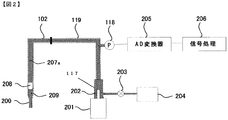
- FIG. 2 is an explanatory view of a main part (pressure signal processing part in the probe 102) in the embodiment of the present invention.
- a narrowed portion 200 having a smaller cross-sectional area than other portions is formed at the tip of the probe 102.
- the metering pump 117 is provided with a plunger 202 (also referred to as a syringe) driven by a drive mechanism 201.
- the metering pump 117 is connected to the pump 204 through the valve 203.
- a pipe 119 (dispensing flow path) is connected to the syringe, and the sample can be sucked into the probe 102 or discharged from the probe 102 by driving the syringe.
- the pressure sensor 118 is connected to a signal processor (signal processing unit) 206 via an AD converter 205.
- the probe 102 is filled with the system liquid 207, and the sample 209 is sucked through the separation air 208.
- the example shown in FIG. 2 shows a state where the sample 209 is sucked into the sample probe 102.
- the probe 102 has a moving mechanism (not shown) and can move up and down and rotate to the sample container 100 and the reaction container 110.
- a sample to be examined such as serum is placed in a sample container 100 and set on a sample disk 101.
- the type of analysis required for each sample is input from the computer 114 to the controller 115.
- a sample collected from the sample container 100 by the sample probe 102 is dispensed into the reaction container 110 arranged on the reaction disk 111.
- the sample probe is a probe that penetrates the stoppered vacuum blood collection tube, sucks the sample in the blood collection tube, and discharges it to the reaction vessel 110.
- reagent container 103 installed on the first reagent disk 104 or the second reagent disk 106 to the reaction container 110 by the first reagent probe 105 or the second reagent probe 107, and is supplied to the stirring device 108. And stirred.
- the sample and reagent dispensing amounts are set in advance for each type of analysis.
- the reaction disk 111 is periodically rotated and stopped, and photometry is performed by the spectroscopic detector 113 at the timing when the reaction vessel 110 passes in front of the light source 112. Photometry is repeated by the spectroscopic detector 113 during the reaction time of 10 minutes, and then the reaction liquid in the reaction vessel 110 is discharged and washed by the vessel washing mechanism 109. In the meantime, in another reaction vessel 110, operations using different samples and reagents are performed in parallel. Data measured by the spectroscopic detector 113 is calculated by the computer 114, and the concentration of the component corresponding to the type of analysis is calculated and displayed on the display of the computer 114.
- the controller 115 opens and closes the valve 203 to fill the flow path of the sample probe 102 with the system liquid 207 supplied from the pump 204.
- the controller 115 lowers the plunger 202 by the drive mechanism 201 while the tip of the probe 102 is in the air, and sucks the separation air 208.
- the controller 115 lowers the probe 102 into the sample container 100 and lowers the plunger 202 by a predetermined amount with the tip immersed in the sample to suck the sample into the probe 102.
- the suction liquid 209 is a sample.
- the pressure fluctuation of the probe 102 during the operation following the suction is detected by the pressure sensor 118, converted into a digital signal by the AD converter 205, and sent to the signal processor 206. Thereafter, the probe 102 is moved onto the reaction vessel 110 to discharge the sample.
- the pressure fluctuation during the operation continued from the time when the probe 102 is discharged is detected again by the pressure sensor 118, converted into a digital signal by the AD converter 205, and sent to the signal processor 206. Subsequently, the inside and outside of the probe 102 is cleaned by opening and closing the valve 203 to prepare for the next analysis.
- the signal processor 206 determines the presence or absence of dispensing abnormality from the pressure waveform at the time of sample aspiration and ejection of the probe 102. If it is determined that there is an abnormality, the analysis is stopped and the display unit of the computer 114 The alarm is displayed on etc. and the recovery operation is performed. The return operation is selected from among other things such as re-dispensing except for the cause of the abnormality, moving to inspection of another sample, and stopping the apparatus.
- FIG. 3 is a diagram for explaining the state in the probe when the sample is sucked from the atmospheric pressure.
- the segmented air 208 is sucked into the probe 102 filled with the system water 207a by a certain amount, and discharged by a certain amount, thereby making the segmented air 208 a certain amount.
- 10 ⁇ L is aspirated and 6 ⁇ L is discharged to set the segmental air to 4 ⁇ L.
- This operation is an operation for canceling individual differences in the amount of backlash (hereinafter referred to as BL) of the syringe.
- FIG. 4 is a diagram for explaining the state in the probe when the inside of the blood collection tube is in a negative pressure state until the sample is sucked.
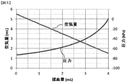
- FIG. 5 shows the pressure change in the vacuum blood collection tube according to the amount of blood collected using the blood collection tube of the same specification.
- the vertical axis represents the air volume and pressure in the vacuum blood collection tube
- the horizontal axis represents the blood collection volume in the vacuum blood collection tube.
- the straight line shown in FIG. 5 shows the relationship between the air volume and the blood collection volume
- the curve shows the relationship between the blood collection volume and the pressure, and it can be seen that the pressure in the vacuum blood collection tube varies depending on the blood collection volume.
- FIG. 6 is a schematic view of the output of the pressure sensor 118 from the start of sample suction.
- the vertical axis represents the pressure due to the output of the pressure sensor 118
- the horizontal axis represents the time axis.
- the segment air quantity is divided according to the line type.
- the waveform shown in FIG. 6 shows the pressure fluctuation at the time of sample suction depending on the segmented air amount, and it can be seen that the pressure waveform at the time of suction changes depending on the segmented air amount even for the same sample.
- the segment air volume decreases as shown in FIG. 6, as the segment air volume decreases, the pressure during suction decreases, and when the sample is actually sucked in a negative pressure state in the vacuum blood collection tube, the segment air volume decreases as shown in FIG. It changes according to the amount of negative pressure.
- the actual amount of negative pressure in the vacuum blood collection tube varies individually, and the amount of segmental air in the probe before aspirating the actual sample varies with the amount of negative pressure in the vacuum blood collection tube. Yes.
- the sample to be sucked from the vacuum blood collection tube is whole blood, and has a viscosity of around 40% when compared to a glycerin aqueous solution.
- the pressure waveform at the time of suction changes even with the same sample, and there is a high risk of determining abnormal suction despite normality.
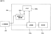
- FIG. 7 is an internal block diagram of the signal processor 206 in the present embodiment.
- the signal processor 206 includes a reference parameter selection unit 206d, a memory 206b, a comparison unit 206a, and a determination unit 206c.
- the determination unit 206 c of the signal processor 206 transmits the determination result to the controller 115.
- the signal processor 206 may be provided separately from the controller 115, or may be provided in the controller 115.
- the reference parameter may be referred to as a clogging detection parameter.
- the memory 206b is a memory that stores a plurality of clogging detection parameters corresponding to the pressure of the vacuum blood collection tube for the same suction amount of the sample.
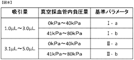
- FIG. 8 is a diagram illustrating a selection example of the reference parameter in the reference parameter selection unit 206d.
- the suction amount is set to 1.0 ⁇ L to 3.0 ⁇ L, 3.1 ⁇ L to 5.0 ⁇ L
- the negative pressure in the vacuum blood collection tube is set to 0 kPa to 40 kPa, 41 kPa to 80 kPa.
- the reference parameter selection unit 206d selects a reference parameter corresponding to the amount of negative pressure in the vacuum blood collection tube from a plurality of reference parameters according to the suction range, and uses the selected reference parameter as a clogging detection parameter during sample suction. . That is, the controller 115 selects the clogging detection parameter stored in the memory 206b according to the pressure in the vacuum blood collection tube, and determines the probe according to the selected clogging detection parameter and the internal pressure at the time of sample suction detected by the pressure sensor. 102 is determined to be clogged.
- the reference parameter to be set is further refined. Two or more may be set.
- the negative pressure must be measured before the probe is inserted into the sample after the probe is inserted into the vacuum blood collection tube or before the sample is aspirated. This is because the selection of the reference parameter needs to be completed at the time of sample aspiration.
- the reference parameter is a parameter for calculating a statistical distance from the pressure.
- the controller 115 acquires a pressure waveform at the time of sample suction (that is, a detection result of the pressure sensor 118) and is selected by the reference parameter selection unit 206d from among a plurality of reference parameters stored in the memory 206b. Reference parameters are obtained, and these statistical distances are calculated.
- the Mahalanobis distance is used as an example of the statistical distance used in the comparison unit 206a will be described.
- the controller 115 compares the calculated statistical distance with the threshold value in the comparison unit 206a, and determines whether the probe is clogged in the determination unit 206c based on the comparison result.
- the threshold value stored in the memory 206b is determined in advance for each subject of the dispensing process or for each dispensing amount. Note that the same threshold value may be used as long as the dispensing amount is the same, thereby simplifying the comparison processing in the comparison unit 206a.
- the statistical distance is an index obtained by quantifying the similarity between two events represented by a plurality of feature variables.
- how far the target data is from a set of known data prepared in advance is calculated.
- a method of calculating the Mahalanobis distance will be described as an example of the statistical distance.
- FIG. 9 is a diagram schematically showing an example of a set of reference parameters.
- each data of n events has k characteristic variables (n and k are positive integers).
- each feature variable of the target data is y 1 , y 2 ,..., Y k
- the average of each feature variable of the known data x nk is z 1 , z 2 ,.
- k and the standard deviation are ⁇ 1 , ⁇ 2 ,..., ⁇ k
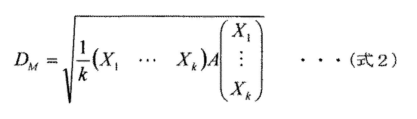
- the Mahalanobis distance D M of the target data for a set of reference parameters is represented by the following (Equation 2).
- Mahalanobis distance D M is a statistical distance, is compared with some predetermined threshold, it is possible to perform the clogging determination of the probe.
- the known data x nk corresponds to a pressure value for a predetermined time of an ideal pressure waveform, and this is a reference parameter.
- Each characteristic variable of the target data is obtained from the pressure waveform at the time of suction of the sample to be detected for clogging, and the Mahalanobis distance D is calculated by using the average and standard deviation of each characteristic variable based on the known data x nk. M can be calculated.
- this known data x nk is represented by Ia in FIG. 8, and a plurality of reference parameters are stored in the memory according to the amount of negative pressure in the vacuum blood collection tube.
- Ib is known data x ′ nk different from Ia.
- the controller selects the reference parameter according to the pressure of the vacuum blood collection tube for the same suction volume, calculates the statistical distance, and compares the calculated statistical distance with the threshold value to determine whether the probe is clogged. Can do.
- the statistical distance calculation method applicable to the present embodiment includes calculation methods such as Euclidean distance, standard Euclidean distance, Manhattan distance, Chebyshev distance, Minkowski distance, and multivariate normal density. is there.
- the reference parameter includes, for example, the minimum pressure value of an ideal pressure waveform of a predetermined negative pressure amount in the vacuum blood collection tube, and when the pressure waveform during sample suction is below this minimum value, clogging is detected. You may judge. In this case, a unique minimum value is stored in the memory in accordance with the negative pressure amount, and the controller selects a minimum value serving as a clogging determination threshold value in accordance with the measured negative pressure amount. In addition to the minimum value, a pressure value at a predetermined time may be used as the clogging determination threshold.
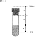
- FIG. 10A is a schematic diagram showing the range of the vacuum blood collection tube.
- a shows from the outside of the vacuum blood collection tube to the inside of the vacuum blood collection tube
- b shows from the inside of the vacuum blood collection tube to the sample liquid surface
- c shows from the sample liquid surface to the suction position.
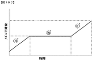
- FIGS. 10B and 10C are relationship diagrams between the nozzle lowering time and the nozzle lowering amount in the vacuum blood collection tube.
- the operation when pushing the probe into the vacuum blood collection tube is as follows.
- A The range drops quickly, and the negative pressure in the vacuum blood collection tube is measured.
- B The range is slowed down and the vacuum pressure is measured.
- C The range is lowered to the suction position at high speed.
- (a) ′ range descends quickly, and the negative pressure in the vacuum blood collection tube is measured.
- the lowering control of these probes is performed by the controller 115.
- the controller 115 controls the lowering operation of the nozzle, and lowers the speed of the lowering operation from the lowering speed penetrating the stopper of the vacuum blood collection tube or stops the lowering operation, thereby reducing the pressure in the vacuum blood collection tube. It is desirable to measure. This is because it does not take too much time until the sample is sucked and the sensitivity of pressure measurement can be increased.
- the controller 115 measures the pressure in the vacuum blood collection tube at a lowering speed than the descending speed that penetrates the stopper of the vacuum blood collection tube, and also drops the drop between the liquid level of the sample and the suction position. It is desirable to perform the descent operation at a speed faster than the desired speed. This is because the sample suction can be performed without taking more time.
- the measurement sensitivity may be increased by measuring the amount of negative pressure by the suction operation of the syringe between the air layers in the vacuum blood collection tube.
- FIG. 11 is a flowchart of the discrimination operation in the present invention.
- the probe 102 is lowered (STEP 1), and after the vacuum blood collection tube is inserted, the pressure inside the vacuum blood collection tube is measured by the pressure sensor 118 (STEP 2).
- the pressure measurement inside the vacuum blood collection tube here, it is only necessary to detect the pressure inside the vacuum blood collection tube, and the state of the descending operation is not limited as described above.
- the reference parameter selection unit 206d selects a reference parameter based on the pressure waveform digital signal sent from the AD converter 205 (STEP 3) and holds it in the memory 206b.
- the selection of the reference parameter requires measurement (STEP 2) and selection of the reference parameter (STEP 3) from the passage through the sealing stopper of the vacuum blood collection tube to the contact with the sample liquid surface.
- the sample is aspirated by the probe 102, and the pressure data at the time of sample aspiration is measured by the pressure sensor 118 (STEP 4).
- the comparison unit 206a compares the pressure data at the time of sample suction with a predetermined threshold value stored in the memory 206b (STEP 5), and the result is supplied to the determination unit 206c.
- the determination unit 206c determines that suction is abnormal (STEP 6).
- the controller 115 controls the discharge operation in accordance with a command from the determination unit 206c (STEP7).
- the present invention it is possible to avoid an influence due to characteristics such as a blood collection tube and a blood collection amount, accurately determine an abnormality during dispensing, and provide a highly reliable automatic analyzer.
- the clogging detection parameter is selected using the pressure result of the pressure sensor 118.
- the pressure result of this pressure sensor is selected. There is no need to use.
- an accurate pressure result for selecting a clogging detection parameter can be obtained without using another pressure detection mechanism.
- the controller 115 measures the pressure in the vacuum blood collection tube with the pressure sensor 118 after the probe plug penetrates and before the sample is sucked. Since the pressure in the vacuum blood collection tube immediately before sample suction can be measured, it is possible to obtain more accurate pressure than the method of measuring or estimating the pressure of the vacuum blood collection tube with another pressure detection mechanism before penetrating the stopper. it can.
- the case where the inside of the vacuum blood collection tube is under negative pressure has been described, but it is needless to say that the clogging determination is effective even when the inside of the vacuum blood collection tube is under pressure and is not a technique limited to negative pressure. .
- a / D converter 206 ... signal processor, 20 a ... comparison unit, 206b ... memory, 206c ... determination unit, 206d ... reference parameter selection unit, 207a ... system water, 207b ... system water, 208 ... segmented air, 208b ... segmental air, 209 ... sample
Landscapes
- Health & Medical Sciences (AREA)
- Life Sciences & Earth Sciences (AREA)
- Physics & Mathematics (AREA)
- Chemical & Material Sciences (AREA)
- Engineering & Computer Science (AREA)
- General Health & Medical Sciences (AREA)
- General Physics & Mathematics (AREA)
- Immunology (AREA)
- Pathology (AREA)
- Biochemistry (AREA)
- Analytical Chemistry (AREA)
- Biomedical Technology (AREA)
- Hematology (AREA)
- Ecology (AREA)
- Biophysics (AREA)
- Molecular Biology (AREA)
- Urology & Nephrology (AREA)
- Food Science & Technology (AREA)
- Medicinal Chemistry (AREA)
- Automatic Analysis And Handling Materials Therefor (AREA)
- Investigating Or Analysing Biological Materials (AREA)
- Sampling And Sample Adjustment (AREA)
Abstract
Description

Claims (14)
- 栓がされている真空採血管に対し当該栓を貫通させ、当該真空採血管内の試料を吸引し、反応容器へ吐出するプローブと、
前記プローブに試料を吸引吐出させるシリンジと、
前記シリンジを接続する分注流路と、
前記分注流路内に配置され、試料吸引時にプローブの内部圧力を検出する圧力センサと、
試料の同一吸引量に対して前記真空採血管の圧力に応じた複数の詰り検知パラメータを記憶するメモリと、
前記真空採血管内の圧力に応じて、前記メモリに記憶された前記詰り検知パラメータを選択し、当該選択された前記詰り検知パラメータと前記圧力センサで検出された試料吸引時の前記内部圧力により、前記プローブの詰り判定を行うコントローラと、を備えることを特徴とする自動分析装置。 - 請求項1記載の自動分析装置において、
前記詰り検知パラメータは、前記内部圧力との統計距離を算出するパラメータであって、
前記コントローラは、前記統計距離と閾値とを比較することで前記プローブの詰り判定を行うことを特徴とする自動分析装置。 - 請求項1記載の自動分析装置において、
前記コントローラは、前記圧力センサにより前記真空採血管内の圧力を測定し、当該測定された圧力に従い前記詰り検知パラメータを選択することを特徴とする自動分析装置。 - 請求項2記載の自動分析装置において、
前記コントローラは、前記圧力センサにより前記真空採血管内の圧力を測定し、当該測定された圧力に従い前記統計距離を算出するパラメータを選択することを特徴とする自動分析装置。 - 請求項3記載の自動分析装置において、
前記コントローラは、前記プローブの前記栓の貫通後、かつ、前記試料の吸引前に前記真空採血管内の圧力を測定することを特徴とする自動分析装置。 - 請求項4記載の自動分析装置において、
前記コントローラは、前記プローブの前記栓の貫通後、かつ、前記試料の吸引前に前記真空採血管内の圧力を測定することを特徴とする自動分析装置。 - 請求項5記載の自動分析装置において、
前記コントローラは、前記シリンジの吸引動作により、前記真空採血管内の圧力を測定することを特徴とする自動分析装置。 - 請求項6記載の自動分析装置において、
前記コントローラは、前記シリンジの吸引動作により、前記真空採血管内の圧力を測定することを特徴とする自動分析装置。 - 請求項5記載の自動分析装置において、
前記コントローラは、前記プローブの下降動作を制御し、
前記コントローラは、前記栓を貫通する下降速度よりも下降動作の速度を落として、若しくは、下降動作を停止させて、前記真空採血管内の圧力を測定することを特徴とする自動分析装置。 - 請求項6記載の自動分析装置において、
前記コントローラは、前記プローブの下降動作を制御し、
前記コントローラは、前記栓を貫通する下降速度よりも下降動作の速度を落として、若しくは、下降動作を停止させて、前記真空採血管内の圧力を測定することを特徴とする自動分析装置。 - 請求項9記載の自動分析装置において、
前記コントローラは、前記栓を貫通する下降速度よりも下降動作の速度を落として、前記真空採血管内の圧力を測定し、前記試料の液面から吸引位置までの間に当該落とした速度よりも早い速度で下降動作を行うことを特徴とする自動分析装置。 - 請求項10記載の自動分析装置において、
前記コントローラは、前記栓を貫通する下降速度よりも下降動作の速度を落として、前記真空採血管内の圧力を測定し、前記試料の液面から吸引位置までの間に当該落とした速度よりも早い速度で下降動作を行うことを特徴とする自動分析装置。 - 請求項1記載の自動分析装置において、
前記真空採血管内の圧力は負圧であることを特徴とする自動分析装置。 - 請求項2記載の自動分析装置において、
前記真空採血管内の圧力は負圧であることを特徴とする自動分析装置。
Priority Applications (4)
| Application Number | Priority Date | Filing Date | Title |
|---|---|---|---|
| CN201580004861.XA CN105917239B (zh) | 2014-01-27 | 2015-01-09 | 自动分析装置 |
| JP2015558795A JP6407895B2 (ja) | 2014-01-27 | 2015-01-09 | 自動分析装置 |
| US15/113,309 US10031152B2 (en) | 2014-01-27 | 2015-01-09 | Automatic analyzer |
| EP15740185.2A EP3101431B1 (en) | 2014-01-27 | 2015-01-09 | Automatic analytical apparatus |
Applications Claiming Priority (2)
| Application Number | Priority Date | Filing Date | Title |
|---|---|---|---|
| JP2014-012070 | 2014-01-27 | ||
| JP2014012070 | 2014-01-27 |
Publications (1)
| Publication Number | Publication Date |
|---|---|
| WO2015111442A1 true WO2015111442A1 (ja) | 2015-07-30 |
Family
ID=53681250
Family Applications (1)
| Application Number | Title | Priority Date | Filing Date |
|---|---|---|---|
| PCT/JP2015/050424 Ceased WO2015111442A1 (ja) | 2014-01-27 | 2015-01-09 | 自動分析装置 |
Country Status (5)
| Country | Link |
|---|---|
| US (1) | US10031152B2 (ja) |
| EP (1) | EP3101431B1 (ja) |
| JP (1) | JP6407895B2 (ja) |
| CN (1) | CN105917239B (ja) |
| WO (1) | WO2015111442A1 (ja) |
Cited By (1)
| Publication number | Priority date | Publication date | Assignee | Title |
|---|---|---|---|---|
| JPWO2022185919A1 (ja) * | 2021-03-04 | 2022-09-09 |
Families Citing this family (11)
| Publication number | Priority date | Publication date | Assignee | Title |
|---|---|---|---|---|
| JP6783674B2 (ja) * | 2017-01-20 | 2020-11-11 | 株式会社日立ハイテク | 自動分析装置、自動分析装置における廃液方法、及び、三方電磁弁 |
| CN108872475A (zh) * | 2018-03-20 | 2018-11-23 | 迈克医疗电子有限公司 | 一种凝块检测的方法、装置、终端设备和介质 |
| CN110926566A (zh) * | 2018-09-20 | 2020-03-27 | 深圳迈瑞生物医疗电子股份有限公司 | 一种液面检测方法、样本分析仪和计算机存储介质 |
| JP7269869B2 (ja) * | 2019-12-05 | 2023-05-09 | 株式会社日立ハイテク | 自動分析装置及び分注方法 |
| JP7417463B2 (ja) * | 2020-04-24 | 2024-01-18 | 株式会社日立ハイテク | 分注装置、自動分析装置、分注方法 |
| CN114113566A (zh) * | 2020-08-28 | 2022-03-01 | 深圳市帝迈生物技术有限公司 | 采样针的堵塞检测方法、血液分析装置及计算机存储介质 |
| CN112858593B (zh) * | 2021-02-22 | 2023-03-28 | 广州科方生物技术股份有限公司 | 一种样本针、试剂针空吸和堵针的检测系统及其检测方法 |
| JP7659447B2 (ja) * | 2021-06-10 | 2025-04-09 | 株式会社日立ハイテク | 分注装置、自動分析装置及び分注方法 |
| CN114166830B (zh) * | 2021-12-08 | 2023-07-14 | 苏州长光华医生物医学工程有限公司 | 一种采样针管路及采样判断方法 |
| CN116007869A (zh) * | 2023-02-09 | 2023-04-25 | 山东省医疗器械和药品包装检验研究院 | 一种真空血样采集容器抽吸体积测试仪器 |
| CN116449044A (zh) * | 2023-04-20 | 2023-07-18 | 三诺生物传感股份有限公司 | 一种加样针状态检测方法及系统 |
Citations (5)
| Publication number | Priority date | Publication date | Assignee | Title |
|---|---|---|---|---|
| EP0747689A2 (en) * | 1995-06-07 | 1996-12-11 | Medical Laboratory Automation, Inc. | Liquid aspiration from a sealed container |
| US5853665A (en) * | 1997-09-16 | 1998-12-29 | Coulter International Corp. | Apparatus and method for monitoring vent line vacuum |
| JPH11503528A (ja) * | 1996-01-19 | 1999-03-26 | ベックマン インスツルメンツ インコーポレーテッド | 診断システムのピペット圧力センサ |
| JP2004125780A (ja) * | 2002-08-07 | 2004-04-22 | Hitachi High-Technologies Corp | サンプル分注装置およびそれを用いた自動分析装置 |
| JP2011085421A (ja) | 2009-10-13 | 2011-04-28 | Aloka Co Ltd | 穿刺ノズル装置 |
Family Cites Families (6)
| Publication number | Priority date | Publication date | Assignee | Title |
|---|---|---|---|---|
| US5130254A (en) | 1990-05-25 | 1992-07-14 | E. I. Du Pont De Nemours And Company | Method for pipetting liquid from a sealed container |
| US7027935B2 (en) * | 2002-08-07 | 2006-04-11 | Hitachi High Technologies Corp. | Sample dispensing apparatus and automatic analyzer using the same |
| FR2919729B1 (fr) * | 2007-08-03 | 2012-03-02 | Horiba Abx Sas | Dispositif de preparation et de distribution fractionnee d'echantillons d'un fluide, systeme de distribution comportant un tel dispositif et procede associe |
| US7867769B2 (en) * | 2007-09-19 | 2011-01-11 | Siemens Healthcare Diagnostics Inc. | Clog detection in a clinical sampling pipette |
| JP5865633B2 (ja) * | 2011-09-01 | 2016-02-17 | 株式会社日立ハイテクノロジーズ | 自動分析装置 |
| JP5899075B2 (ja) * | 2012-07-20 | 2016-04-06 | 株式会社日立ハイテクノロジーズ | 自動分析装置 |
-
2015
- 2015-01-09 US US15/113,309 patent/US10031152B2/en active Active
- 2015-01-09 EP EP15740185.2A patent/EP3101431B1/en active Active
- 2015-01-09 WO PCT/JP2015/050424 patent/WO2015111442A1/ja not_active Ceased
- 2015-01-09 CN CN201580004861.XA patent/CN105917239B/zh active Active
- 2015-01-09 JP JP2015558795A patent/JP6407895B2/ja active Active
Patent Citations (5)
| Publication number | Priority date | Publication date | Assignee | Title |
|---|---|---|---|---|
| EP0747689A2 (en) * | 1995-06-07 | 1996-12-11 | Medical Laboratory Automation, Inc. | Liquid aspiration from a sealed container |
| JPH11503528A (ja) * | 1996-01-19 | 1999-03-26 | ベックマン インスツルメンツ インコーポレーテッド | 診断システムのピペット圧力センサ |
| US5853665A (en) * | 1997-09-16 | 1998-12-29 | Coulter International Corp. | Apparatus and method for monitoring vent line vacuum |
| JP2004125780A (ja) * | 2002-08-07 | 2004-04-22 | Hitachi High-Technologies Corp | サンプル分注装置およびそれを用いた自動分析装置 |
| JP2011085421A (ja) | 2009-10-13 | 2011-04-28 | Aloka Co Ltd | 穿刺ノズル装置 |
Non-Patent Citations (1)
| Title |
|---|
| See also references of EP3101431A4 |
Cited By (2)
| Publication number | Priority date | Publication date | Assignee | Title |
|---|---|---|---|---|
| JPWO2022185919A1 (ja) * | 2021-03-04 | 2022-09-09 | ||
| JP7539547B2 (ja) | 2021-03-04 | 2024-08-23 | 株式会社日立ハイテク | 自動分析装置、および検体の分注方法 |
Also Published As
| Publication number | Publication date |
|---|---|
| US20170010294A1 (en) | 2017-01-12 |
| CN105917239B (zh) | 2017-09-22 |
| JP6407895B2 (ja) | 2018-10-17 |
| EP3101431A4 (en) | 2017-10-25 |
| CN105917239A (zh) | 2016-08-31 |
| US10031152B2 (en) | 2018-07-24 |
| JPWO2015111442A1 (ja) | 2017-03-23 |
| EP3101431A1 (en) | 2016-12-07 |
| EP3101431B1 (en) | 2022-03-30 |
Similar Documents
| Publication | Publication Date | Title |
|---|---|---|
| JP6407895B2 (ja) | 自動分析装置 | |
| JP5865633B2 (ja) | 自動分析装置 | |
| JP5899075B2 (ja) | 自動分析装置 | |
| JP6567890B2 (ja) | 自動分析装置 | |
| US9857388B2 (en) | Automatic analyzer | |
| JP6602753B2 (ja) | 自動分析装置 | |
| JP6649942B2 (ja) | 自動分析装置 | |
| WO2014034293A1 (ja) | 自動分析装置 | |
| JP2004271266A (ja) | 分注装置およびそれを用いた自動分析装置 | |
| JP6654881B2 (ja) | 自動分析装置及び自動分析装置の異常判定方法 | |
| JP6121743B2 (ja) | 自動分析装置 |
Legal Events
| Date | Code | Title | Description |
|---|---|---|---|
| 121 | Ep: the epo has been informed by wipo that ep was designated in this application |
Ref document number: 15740185 Country of ref document: EP Kind code of ref document: A1 |
|
| ENP | Entry into the national phase |
Ref document number: 2015558795 Country of ref document: JP Kind code of ref document: A |
|
| REEP | Request for entry into the european phase |
Ref document number: 2015740185 Country of ref document: EP |
|
| WWE | Wipo information: entry into national phase |
Ref document number: 15113309 Country of ref document: US Ref document number: 2015740185 Country of ref document: EP |
|
| NENP | Non-entry into the national phase |
Ref country code: DE |