WO2015111625A1 - 電動機、電動パワーステアリング装置及び車両 - Google Patents
電動機、電動パワーステアリング装置及び車両 Download PDFInfo
- Publication number
- WO2015111625A1 WO2015111625A1 PCT/JP2015/051551 JP2015051551W WO2015111625A1 WO 2015111625 A1 WO2015111625 A1 WO 2015111625A1 JP 2015051551 W JP2015051551 W JP 2015051551W WO 2015111625 A1 WO2015111625 A1 WO 2015111625A1
- Authority
- WO
- WIPO (PCT)
- Prior art keywords
- electric motor
- rotor
- rotor yoke
- motor
- magnetic gap
- Prior art date
- Legal status (The legal status is an assumption and is not a legal conclusion. Google has not performed a legal analysis and makes no representation as to the accuracy of the status listed.)
- Ceased
Links
Images


Classifications
-
- H—ELECTRICITY
- H02—GENERATION; CONVERSION OR DISTRIBUTION OF ELECTRIC POWER
- H02K—DYNAMO-ELECTRIC MACHINES
- H02K1/00—Details of the magnetic circuit
- H02K1/06—Details of the magnetic circuit characterised by the shape, form or construction
- H02K1/22—Rotating parts of the magnetic circuit
- H02K1/27—Rotor cores with permanent magnets
- H02K1/2706—Inner rotors
-
- B—PERFORMING OPERATIONS; TRANSPORTING
- B62—LAND VEHICLES FOR TRAVELLING OTHERWISE THAN ON RAILS
- B62D—MOTOR VEHICLES; TRAILERS
- B62D5/00—Power-assisted or power-driven steering
- B62D5/04—Power-assisted or power-driven steering electrical, e.g. using an electric servo-motor connected to, or forming part of, the steering gear
-
- H—ELECTRICITY
- H02—GENERATION; CONVERSION OR DISTRIBUTION OF ELECTRIC POWER
- H02K—DYNAMO-ELECTRIC MACHINES
- H02K1/00—Details of the magnetic circuit
- H02K1/06—Details of the magnetic circuit characterised by the shape, form or construction
- H02K1/22—Rotating parts of the magnetic circuit
- H02K1/24—Rotor cores with salient poles ; Variable reluctance rotors
- H02K1/246—Variable reluctance rotors
-
- H—ELECTRICITY
- H02—GENERATION; CONVERSION OR DISTRIBUTION OF ELECTRIC POWER
- H02K—DYNAMO-ELECTRIC MACHINES
- H02K1/00—Details of the magnetic circuit
- H02K1/06—Details of the magnetic circuit characterised by the shape, form or construction
- H02K1/22—Rotating parts of the magnetic circuit
- H02K1/27—Rotor cores with permanent magnets
- H02K1/2706—Inner rotors
- H02K1/272—Inner rotors the magnetisation axis of the magnets being perpendicular to the rotor axis
- H02K1/274—Inner rotors the magnetisation axis of the magnets being perpendicular to the rotor axis the rotor consisting of two or more circumferentially positioned magnets
- H02K1/2753—Inner rotors the magnetisation axis of the magnets being perpendicular to the rotor axis the rotor consisting of two or more circumferentially positioned magnets the rotor consisting of magnets or groups of magnets arranged with alternating polarity
- H02K1/278—Surface mounted magnets; Inset magnets
-
- H—ELECTRICITY
- H02—GENERATION; CONVERSION OR DISTRIBUTION OF ELECTRIC POWER
- H02K—DYNAMO-ELECTRIC MACHINES
- H02K1/00—Details of the magnetic circuit
- H02K1/06—Details of the magnetic circuit characterised by the shape, form or construction
- H02K1/12—Stationary parts of the magnetic circuit
- H02K1/14—Stator cores with salient poles
- H02K1/146—Stator cores with salient poles consisting of a generally annular yoke with salient poles
-
- H—ELECTRICITY
- H02—GENERATION; CONVERSION OR DISTRIBUTION OF ELECTRIC POWER
- H02K—DYNAMO-ELECTRIC MACHINES
- H02K29/00—Motors or generators having non-mechanical commutating devices, e.g. discharge tubes or semiconductor devices
- H02K29/06—Motors or generators having non-mechanical commutating devices, e.g. discharge tubes or semiconductor devices with position sensing devices
Definitions
- the present invention relates to an electric motor, an electric power steering device, and a vehicle.
- Patent Document 1 has a structure in which a permanent magnet is embedded in a rotor, and a permanent magnet embedded motor that uses a torque obtained by adding a magnet torque and a reluctance torque smaller than the magnet torque, so-called IPM (Interior Permanent Magnet). ) Motor is described.
- IPM Interior Permanent Magnet
- the present invention has been made in view of the above, and includes a plurality of magnets provided on the outer periphery of the rotor yoke and arranged in the circumferential direction of the rotor yoke, and the ratio of the d-axis inductance and the q-axis inductance is determined.
- An object is to provide an electric motor, an electric power steering device, and a vehicle that can increase a certain salient pole ratio and use reluctance torque.
- an electric motor includes a rotor yoke, and a plurality of magnets provided on an outer periphery of the rotor yoke and arranged in a circumferential direction of the rotor yoke;
- a stator core disposed in an annular shape on the radially outer side of the rotor yoke and a motor stator including an exciting coil for exciting the stator core, and an outer periphery of the rotor yoke has a convex portion protruding radially outward of the rotor yoke;
- a concave portion between the convex portions adjacent in the circumferential direction, and the magnet is disposed on the concave surface.
- the salient pole ratio which is the ratio between the d-axis inductance and the q-axis inductance, can be increased and reluctance torque can be used. Moreover, torque ripple is suppressed and the controllability of the electric motor is improved.
- the convex portion has at least one magnetic gap portion that penetrates the interior of the rotor yoke in an axial direction parallel to the axis of rotation of the motor rotor and has a lower magnetic permeability than the rotor yoke.
- the salient pole ratio which is the ratio between the d-axis inductance and the q-axis inductance, can be increased.
- the center of curvature of the outer diameter on the outer side of the magnet is deviated from the rotation center of the motor rotor. This structure contributes to the reduction of torque ripple by controlling the flow of the outer diameter magnetic flux on the radially outer side of the magnet.
- the magnetic gap portion has a curved shape at the end portion on the radially outer side of the convex portion as viewed from the axial direction.
- the magnetic gap portion of the convex portion and the magnetic gap portion of the convex portion adjacent in the circumferential direction are closer to the radially inner end than the radially outer end.
- the end portions on the inner side in the radial direction are spaced apart from each other to form a magnetic path.
- the concave portion includes a linearly inclined portion when viewed in the axial direction between the concave surface where the magnet is disposed and the outermost periphery of the convex portion.
- the magnetic gap portion has an arc drawn at a virtual center where at least a part of the edge seen in the axial direction is closer to the stator core than the concave surface where the magnet is disposed. It is preferable to include.
- the magnetic gap portion includes a nonmagnetic material.
- the rigidity of the rotor yoke can be increased.
- the magnetic gap portion may be a gap. However, if many gaps are formed in the rotor yoke, the rigidity of the rotor yoke may be reduced. For this reason, the magnetic gap portion can increase the rigidity of the rotor yoke by filling the inside with a nonmagnetic material equivalent to air in terms of a magnetic circuit.
- the above-described electric motor is preferably used for electric power steering for obtaining auxiliary steering torque.
- an electric power steering device that obtains an auxiliary steering torque by the electric motor is preferable.
- a vehicle including the electric motor is preferable.
- hysteresis loss is reduced when the magnetic domains generated in the stator core change direction.
- Hysteresis loss is considered to be a cause of increase in loss torque when the motor is idling. That is, even in the case of a sudden stop, it is possible to suppress an increase in loss torque (electromagnetic brake) when the rotor of the motor runs idle. Since the loss torque can be suppressed, the electric power steering apparatus can operate in a state in which a sense of discomfort is suppressed even if the auxiliary steering torque is transmitted to the steering person.
- a plurality of magnets are provided on the outer periphery of the rotor yoke and arranged in the circumferential direction of the rotor yoke, the salient pole ratio that is the ratio of the d-axis inductance and the q-axis inductance is increased, and the reluctance torque is increased.
- An electric motor and an electric power steering device can be provided.
- FIG. 1 is a configuration diagram of an electric power steering apparatus including an electric motor according to the present embodiment.
- FIG. 2 is a front view for explaining an example of a speed reducer included in the electric power steering apparatus of the present embodiment.
- FIG. 3 is a cross-sectional view schematically showing the configuration of the electric motor of the present embodiment on a virtual plane including the central axis.
- FIG. 4 is a cross-sectional view schematically showing the configuration of the electric motor according to the present embodiment, taken along a virtual plane orthogonal to the central axis.
- FIG. 5 is an explanatory diagram schematically showing the configuration of the motor rotor of the present embodiment.
- FIG. 6 is an explanatory diagram when the electric motor according to the present embodiment is applied as a direct drive motor.
- FIG. 1 is a configuration diagram of an electric power steering apparatus including an electric motor according to the present embodiment.
- FIG. 2 is a front view for explaining an example of a speed reducer included in the electric power steering apparatus of the present embodiment.
- FIG. 7 is an explanatory diagram illustrating an evaluation example of the flow of magnetic flux according to the electric motor according to the present embodiment.
- FIG. 8 is an explanatory diagram for explaining an evaluation example of the flow of magnetic flux related to the electric motor according to the comparative example.
- FIG. 9 is an explanatory diagram illustrating an evaluation example of the flow of magnetic flux according to the electric motor according to the present embodiment.
- FIG. 10 is an explanatory diagram illustrating an evaluation example of the flow of magnetic flux related to the electric motor according to the comparative example.
- FIG. 11 is an explanatory diagram illustrating an evaluation example of the flow of magnetic flux according to the electric motor according to the present embodiment.
- FIG. 12 is an explanatory diagram illustrating an evaluation example of the flow of magnetic flux related to the electric motor according to the comparative example.
- FIG. 13 is an explanatory diagram illustrating an evaluation example of the flow of magnetic flux according to the electric motor according to the present embodiment.
- FIG. 14 is an explanatory diagram illustrating an evaluation example of the flow of magnetic flux related to the electric motor according to the comparative example.
- FIG. 15 is a schematic diagram of a vehicle equipped with an electric power steering apparatus including the electric motor according to the present embodiment.
- FIG. 1 is a configuration diagram of an electric power steering apparatus including an electric motor according to the present embodiment. This embodiment demonstrates the outline
- the electric power steering device 80 includes a steering wheel 81, a steering shaft 82, a steering force assist mechanism 83, a universal joint 84, a lower shaft 85, a universal joint 86, in the order in which the force applied from the steering wheel is transmitted.
- a pinion shaft 87, a steering gear 88, and a tie rod 89 are provided.
- the electric power steering apparatus 80 includes an ECU (Electronic Control Unit) 90, a torque sensor 91a, and a vehicle speed sensor 91b.
- ECU Electronic Control Unit
- the steering shaft 82 includes an input shaft 82a and an output shaft 82b.
- the input shaft 82a has one end connected to the steering wheel 81 and the other end connected to the steering force assist mechanism 83 via the torque sensor 91a.
- the output shaft 82 b has one end connected to the steering force assist mechanism 83 and the other end connected to the universal joint 84.
- the input shaft 82a and the output shaft 82b are made of a magnetic material such as iron.
- the lower shaft 85 has one end connected to the universal joint 84 and the other end connected to the universal joint 86.
- the pinion shaft 87 has one end connected to the universal joint 86 and the other end connected to the steering gear 88.
- the steering gear 88 includes a pinion 88a and a rack 88b.
- the pinion 88a is connected to the pinion shaft 87.
- the rack 88b meshes with the pinion 88a.
- the steering gear 88 is configured as a rack and pinion type.
- the steering gear 88 converts the rotational motion transmitted to the pinion 88a into a linear motion by the rack 88b.
- the tie rod 89 is connected to the rack 88b.
- the steering force assist mechanism 83 includes a speed reducer 92 and the electric motor 10.
- the reduction gear 92 is connected to the output shaft 82b.
- the electric motor 10 is an electric motor that is connected to the reduction gear 92 and generates auxiliary steering torque.
- a steering column is constituted by the steering shaft 82, the torque sensor 91a, and the speed reducer 92.
- the electric motor 10 gives auxiliary steering torque to the output shaft 82b of the steering column. That is, the electric power steering apparatus 80 of this embodiment is a column assist system.
- the column assist type electric power steering device 80 has a relatively short distance between the operator and the electric motor 10, and the torque change or frictional force of the electric motor 10 may affect the steering person. For this reason, the electric power steering apparatus 80 is required to reduce the frictional force of the electric motor 10.
- FIG. 2 is a front view for explaining an example of a speed reducer provided in the electric power steering apparatus of the present embodiment.
- the speed reducer 92 is a worm speed reducer.
- the reduction gear 92 includes a reduction gear housing 93, a worm 94, a ball bearing 95 a, a ball bearing 95 b, a worm wheel 96, and a holder 97.
- the worm 94 is coupled to the shaft 21 of the electric motor 10 by a spline or an elastic coupling.
- the worm 94 is held in the speed reducer housing 93 so as to be rotatable by a ball bearing 95 a and a ball bearing 95 b held by the holder 97.
- the worm wheel 96 is rotatably held by the speed reducer housing 93.
- the worm teeth 94 a formed on a part of the worm 94 mesh with the worm wheel teeth 96 a formed on the worm wheel 96.
- Rotational force of the electric motor 10 is transmitted to the worm wheel 96 through the worm 94 to rotate the worm wheel 96.
- the reduction gear 92 increases the torque of the electric motor 10 by the worm 94 and the worm wheel 96. Then, the reduction gear 92 gives an auxiliary steering torque to the output shaft 82b of the steering column shown in FIG.
- the torque sensor 91a shown in FIG. 1 detects the driver's steering force transmitted to the input shaft 82a through the steering wheel 81 as a steering torque.
- the vehicle speed sensor 91b detects the traveling speed of the vehicle on which the electric power steering device 80 is mounted. In the ECU 90, the electric motor 10, the torque sensor 91a, and the vehicle speed sensor 91b are electrically connected.
- the ECU 90 controls the operation of the electric motor 10. Moreover, ECU90 acquires a signal from each of the torque sensor 91a and the vehicle speed sensor 91b. That is, the ECU 90 acquires the steering torque T from the torque sensor 91a, and acquires the traveling speed V of the vehicle from the vehicle speed sensor 91b.
- the ECU 90 is supplied with electric power from a power supply device (for example, a vehicle-mounted battery) 99 with the ignition switch 98 turned on.
- the ECU 90 calculates an assist steering command value of the assist command based on the steering torque T and the traveling speed V. Then, the ECU 90 adjusts the electric power value X supplied to the electric motor 10 based on the calculated auxiliary steering command value.
- the ECU 90 acquires the information on the induced voltage from the electric motor 10 or the information on the rotation of the rotor from the resolver described later as the operation information Y.
- the steering force of the driver (driver) input to the steering wheel 81 is transmitted to the speed reduction device 92 of the steering force assist mechanism 83 via the input shaft 82a.
- the ECU 90 acquires the steering torque T input to the input shaft 82a from the torque sensor 91a, and acquires the traveling speed V from the vehicle speed sensor 91b.
- the ECU 90 controls the operation of the electric motor 10.
- the auxiliary steering torque created by the electric motor 10 is transmitted to the speed reducer 92.
- the steering torque T (including auxiliary steering torque) output via the output shaft 82 b is transmitted to the lower shaft 85 via the universal joint 84 and further transmitted to the pinion shaft 87 via the universal joint 86.
- the steering force transmitted to the pinion shaft 87 is transmitted to the tie rod 89 via the steering gear 88 to steer the steered wheels.
- the electric motor 10 will be described.
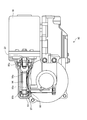
- FIG. 3 is a cross-sectional view schematically showing the configuration of the electric motor of the present embodiment on a virtual plane including the central axis.
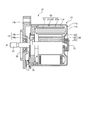
- FIG. 4 is a cross-sectional view schematically showing the configuration of the electric motor according to the present embodiment, taken along a virtual plane orthogonal to the central axis.
- the electric motor 10 includes a housing 11, a bearing 12, a bearing 13, a resolver 14, a motor rotor 20, and a motor stator 30 for a brushless motor.
- the housing 11 includes a cylindrical housing 11a and a front bracket 11b.
- the front bracket 11b is formed in a substantially disc shape and is attached to the cylindrical housing 11a so as to close one open end of the cylindrical housing 11a.
- the cylindrical housing 11a is formed with a bottom 11c at the end opposite to the front bracket 11b so as to close the end.
- the bottom part 11c is formed integrally with the cylindrical housing 11a, for example.
- a material for forming the cylindrical housing 11a for example, a general steel material such as SPCC (Steel Plate Cold Commercial), electromagnetic soft iron, aluminum, or the like can be applied.
- the front bracket 11b plays a role of a flange when the electric motor 10 is attached to a desired device.
- the bearing 12 is provided on the inner side of the cylindrical housing 11a and substantially at the center of the front bracket 11b.
- the bearing 13 is provided inside the cylindrical housing 11a and at a substantially central portion of the bottom portion 11c.
- the bearing 12 rotatably supports one end of a shaft 21 that is a part of the motor rotor 20 disposed inside the cylindrical housing 11a.
- the bearing 13 rotatably supports the other end of the shaft 21. Thereby, the shaft 21 rotates around the axis of the rotation center Zr.
- the resolver 14 is supported by a terminal block 15 provided on the front bracket 11b side of the shaft 21.
- the resolver 14 detects the rotational position of the motor rotor 20 (shaft 21).
- the resolver 14 includes a resolver rotor 14a and a resolver stator 14b.
- the resolver rotor 14a is attached to the circumferential surface of the shaft 21 by press fitting or the like.
- the resolver stator 14b is disposed to face the resolver rotor 14a with a predetermined gap.
- the motor stator 30 is provided in a cylindrical shape so as to surround the motor rotor 20 inside the cylindrical housing 11a.
- the motor stator 30 is attached by being fitted, for example, to the inner peripheral surface 11d of the cylindrical housing 11a.
- the central axis of the motor stator 30 coincides with the rotation center Zr of the motor rotor 20.
- the motor stator 30 includes a cylindrical stator core 31 and an excitation coil 37. In the motor stator 30, an exciting coil 37 is wound around a stator core 31.
- the stator core 31 includes a plurality of teeth 34. There are nine teeth 34 in the circumferential direction of the present embodiment.
- the stator core 31 is formed by stacking and bundling a plurality of core pieces formed in substantially the same shape in the axial direction parallel to the axis of the rotation center Zr.
- a tooth tip 32 protrudes in the circumferential direction on the inner peripheral side of the tooth 34, and the inner peripheral surface 32 ⁇ / b> F of the tooth 34 faces the outer periphery of the rotor yoke 22 with a gap G therebetween.
- the stator core 31 is made of a magnetic material such as an electromagnetic steel plate.
- the stator core 31 has a back yoke 33 and teeth 34.
- the back yoke 33 includes an arc-shaped portion.
- the back yoke 33 has an annular shape.
- the teeth 34 are portions extending from the inner peripheral surface of the back yoke 33 toward the motor rotor 20.
- the plurality of teeth 34 are arranged at equal intervals in the circumferential direction around the rotation center Zr (the direction along the inner peripheral surface 11d of the cylindrical housing 11a shown in FIGS. 3 and 4).
- the circumferential direction around the rotation center Zr is simply referred to as the circumferential direction.
- the stator core 31 is press-fitted into the cylindrical housing 11a, so that the motor stator 30 is provided inside the cylindrical housing 11a in an annular state.
- the stator core 31 and the cylindrical housing 11a may be fixed by adhesion, shrink fitting, welding or the like in addition to press-fitting.
- the exciting coil 37 shown in FIG. 4 is a linear electric wire.
- the exciting coil 37 is concentratedly wound around the outer periphery of the tooth 34 via an insulator 37a (see FIG. 3).
- the number of magnetic poles can be reduced, and the coil amount can be reduced because the coil ends are shortened compared to distributed winding. As a result, cost can be reduced and the electric motor 10 can be made compact.
- the exciting coil 37 may be distributedly wound around a plurality of teeth 34. With this configuration, the number of magnetic poles is increased and the distribution of magnetic flux is stabilized, so that torque ripple can be suppressed.
- the exciting coil 37 may be toroidally wound around the outer periphery of the back yoke 33. With this configuration, a magnetic flux distribution equivalent to the distributed winding is generated, and the coil end is shortened compared to the distributed winding, so that the coil amount can be reduced. As a result, torque ripple can be suppressed and the electric motor 10 can be made compact.
- the insulator 37a shown in FIG. 3 is a member for insulating the exciting coil 37 and the stator core 31, and is formed of a heat-resistant member.
- the motor stator 30 has a shape that can surround the motor rotor 20. That is, the stator core 31 is annularly arranged with a predetermined gap (gap) G on the radially outer side of the rotor yoke 22 described later.
- the motor rotor 20 is provided inside the cylindrical housing 11a so that it can rotate around the rotation center Zr with respect to the cylindrical housing 11a.
- the motor rotor 20 includes a shaft 21, a rotor yoke 22, and a magnet 23.
- the shaft 21 is formed in a cylindrical shape.
- the rotor yoke 22 is formed in a cylindrical shape.
- the rotor yoke 22 has an arcuate outer periphery. With this configuration, the rotor yoke 22 can reduce the number of stamping processes compared to a case where the outer periphery has a complicated shape.
- the rotor yoke 22 is manufactured by laminating thin plates such as electromagnetic steel plates and cold rolled steel plates by means of adhesion, boss, caulking or the like.
- the rotor yoke 22 is sequentially stacked in the mold and discharged from the mold.
- the rotor yoke 22 is fixed to the shaft 21 by press-fitting the shaft 21 into, for example, a hollow portion thereof.
- the shaft 21 and the rotor yoke 22 may be integrally formed.
- the magnet 23 is fixed to the surface along the circumferential direction of the rotor yoke 22, and a plurality of magnets 23 are provided.
- the magnet 23 is a permanent magnet, and S poles and N poles are alternately arranged at equal intervals in the circumferential direction of the rotor yoke 22. Accordingly, the number of poles of the motor rotor 20 shown in FIG. 4 is six poles in which the N pole and the S pole are alternately arranged in the circumferential direction of the rotor yoke 22 on the outer peripheral side of the rotor yoke 22.
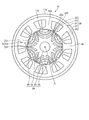
- FIG. 5 is an explanatory diagram schematically showing the configuration of the motor rotor of the present embodiment.
- the outer periphery of the rotor yoke 22 includes a convex portion 22q protruding outward in the radial direction of the rotor yoke 22 and a concave portion 22d between the convex portions 22q adjacent in the circumferential direction.
- the convex portions 22q and the concave portions 22d are alternately arranged in the circumferential direction.
- the convex portion 22q is provided with through holes formed in the rotor yoke 22 in the axial direction (hereinafter referred to as the axial direction) parallel to the rotation center Zr of the motor rotor 20 as a magnetic gap portion g1 and a magnetic gap portion g2. ing.
- the magnetic gap part g ⁇ b> 1 and the magnetic gap part g ⁇ b> 2 are air gaps that penetrate the rotor yoke 22 and have a permeability lower than that of the rotor yoke 22.
- the magnetic gap part g1 and the magnetic gap part g2 can suppress or block the passage of magnetic flux.
- the magnetic gap part g1 and the magnetic gap part g2 may be filled with a nonmagnetic material such as a thermosetting resin so as to include a nonmagnetic material. With this structure, the rigidity of the rotor yoke 22 can be ensured.
- the magnet 23 is accommodated in the recess 22d of the rotor yoke 22, and is attached by, for example, a magnetic force.
- the magnet 23 is a segment magnet having a segmented shape (segment structure) that is fixed to the surface along the circumferential direction of the rotor yoke 22 and is provided in plural.
- the magnet 23 has a so-called kamaboko-shaped cross section in the axial direction.
- the concave portion 22d of the rotor yoke 22 includes a pasting surface 22a on which the magnet 23 is disposed, and an inclined portion 22b between the pasting surface 22a and the convex portion 22q and having a linear portion in the axial cross section.
- the axial cross section of the magnet 23 is the radially inner side surface 23a, the circumferential end surfaces 23b and 23c, and the radially outer side surface 23p, the radially inner side surface 23a is the sticking surface 22a. In surface contact.
- the sticking surface 22a has a radius of curvature r22 centered on the rotation center Zr that is smaller than the radius of curvature r23 of the circumferential arc of the outermost surface of the convex portion 22q.
- the outer surface 23p on the outer side in the radial direction has a radius of curvature r23 that is approximately the same as the circumferential arc of the outermost surface of the convex portion 22q.
- the gap G2 is surrounded by the circumferential end faces 23b and 23c, the inclined portion 22b, and the inner peripheral surface 32F of the tooth 34. Space.
- the magnet 23 having the N pole magnetized on the outer peripheral side of the rotor yoke 22 and the magnet 23 having the S pole magnetized on the outer peripheral side of the rotor yoke 22 They are alternately arranged at equal intervals in the circumferential direction.
- the magnet 23 is configured such that the curvature of the outer surface 23p on the radially outer side is different from the curvature of the attaching surface 22a of the recess 22d.
- the electric motor 10 includes a magnetic gap part g1 and a magnetic gap part g2 on the convex part 22q of the rotor yoke 22, so that a difference in magnetic resistance occurs on the outer periphery of the rotor yoke 22.
- the magnetic gap part g1 of the convex part 22q and the magnetic gap part g1 of the convex part 22q adjacent in the circumferential direction are such that the radially inner end parts g1ea are closer to each other than the radially outer end parts g1eb. Between the extended ends g1ea in the radial direction, there are gaps md1 and md2 that become magnetic paths.
- the magnetic gap part g2 of the convex part 22q and the magnetic gap part g2 of the convex part 22q adjacent in the circumferential direction are such that the radially inner end parts g2ea are closer to each other than the radially outer end parts g2eb. It extends and has an interval md3 at which the radially inner end g2ea becomes a magnetic path.
- the magnetic gap part g2 of the convex part 22q and the magnetic gap part g2 of the convex part 22q adjacent in the circumferential direction are symmetrical with respect to the virtual line gs.
- the magnetic gap part g1 of the convex part 22q and the magnetic gap part g1 of the convex part 22q adjacent in the circumferential direction have a line-symmetric shape with respect to the virtual line gs.
- the intervals md1, md2, and md3 described above are narrowed in the order of the intervals md1, md2, and md3.
- the magnetic gap part g1 has an imaginary center (in this embodiment, a virtual reference point gr) in which at least a part of the edge viewed in the axial direction is closer to the stator core 31 than the inner surface 23a (recessed part surface) on which the magnet 23 is disposed. ), Including an arc drawn with a radius of curvature gr1.
- the magnetic gap portion g2 has an imaginary center (in this embodiment, a virtual reference point gr) in which at least a part of the edge viewed in the axial direction is closer to the stator core 31 than the inner side surface 23a (recess surface) where the magnet 23 is disposed. ), Including an arc drawn with a radius of curvature gr2.
- the distance gd between the magnetic gap part g1 and the magnetic gap part g2 is substantially constant, and the magnetic flux flows through the rotor yoke 22 between the magnetic gap part g1 and the magnetic gap part g2. It becomes like this.
- the motor rotor 20 is provided with a bridge portion 22f through which magnetic flux passes on the outer side in the radial direction of the magnetic gap portion g1 and the magnetic gap portion g2.
- the shapes of the end parts g1eb and g2eb on the outer side in the radial direction are curved when viewed from the axial direction.
- the radial thickness ⁇ f of the bridge portion 22f is smaller than the width g1wb of the end portion g1eb on the radially outer side of the magnetic gap portion g1.
- the radial thickness ⁇ f of the bridge portion 22f is smaller than the width g2wb of the end portion g2eb on the outer side in the radial direction of the magnetic gap portion g2.
- the short circuit of the magnetic flux flowing in the rotor yoke 22 (distance gd) between the adjacent magnetic gap portion g1 and magnetic gap portion g2 is suppressed. it can. Moreover, it can suppress that it becomes a path
- the magnetic gap part g1 is disposed closer to the rotation center Zr than the magnetic gap part g2.
- the width g2wb of the radially outer end portion g2eb is approximately the same as the width g2wa of the radially inner end portion g2ea.
- the width g1wa of the radially inner end g1ea is wider than the width g1wb of the radially outer end g1eb.
- the magnetic gap portion g1 extends so that the radially outer ends leave a magnetic path having a width ge and run parallel to the radially outer side from the rotation center Zr.
- the magnetic gap part g1 is a state in which the magnetic bodies of the rotor yoke 22 remain between the magnetic gap parts g1 with the radially outer ends leaving a magnetic path having a width ge.
- the magnetic gap portion g1 of the present embodiment is not limited to this mode, and the magnetic body of the rotor yoke 22 between the adjacent magnetic gap portions g1 is eliminated at the radially outer end portion of the adjacent magnetic gap portions g1 and is magnetic.
- the gap part may be integrated.
- convex portions 22q and magnets 23 are alternately arranged on the outer periphery of the rotor yoke 22.
- the magnet 23 is a convex portion that protrudes radially outward of the rotor yoke 22 as a shape, and is a magnetic convex portion that has a large magnetic resistance and a small inductance.
- the magnet 23 which is a magnetic convex part is called a d-axis, and a position magnetically different from this by 90 ° in phase is called a q-axis.
- the magnetic recess has a small magnetic resistance and a large inductance.
- a gap G which is a predetermined distance between the stator core 31 and the rotor yoke 22, changes in the order of the gaps G 1, G 2, G 3, G 2, G 1 as the rotor yoke 22 rotates.
- the magnet 23 is fixed to the surface of the rotor yoke 22, and a magnetic path circuit is formed by the magnetic gap part g1 and the magnetic gap part g2 on the convex part 22q, so that the motor rotor 20 has the following structure (1).
- the average torque Tt is a reluctance torque Tr due to magnetic unevenness generated on the outer periphery of the rotor yoke 22. As a result, even if the magnetic flux interlinking from the rotor yoke 22 to the stator core 31 is reduced, the average torque Tt generated in the motor rotor 20 is improved.
- the electric motor 10 includes a motor rotor 20 and a motor stator 30.
- the motor rotor 20 includes a rotor yoke 22 and a plurality of magnets 23 provided on the outer periphery of the rotor yoke 22 and arranged in the circumferential direction of the rotor yoke 22.
- the motor stator 30 includes a stator core 31 arranged in an annular shape and an exciting coil 37 that excites the stator core 31 outside the rotor yoke 22 in the radial direction.
- the outer periphery of the rotor yoke 22 includes a convex portion 22q protruding outward in the radial direction of the rotor yoke 22 and a concave portion 22d between the convex portions 22q adjacent in the circumferential direction.
- the magnet 23 is disposed on the sticking surface 22a which is the surface of the concave portion 22d.
- the convex portion 22q penetrates the inside of the rotor yoke 22 in the axial direction, and has a magnetic permeability lower than that of the rotor yoke 22 and forms a magnetic gap. At least one of a magnetic gap part g1 and a magnetic gap part g2 is provided.
- reluctance torque acts to increase the q-axis inductance
- the salient pole ratio which is the ratio of the q-axis inductance to the d-axis inductance
- the rare earth magnet component of the motor or magnet that reduces the amount of magnet used can be reduced, and the reluctance torque can be used to ensure the average torque Tt of the motor rotor 20 even if the magnet torque generated by the magnet is small. it can.
- sufficient torque can be obtained and costs can be suppressed.
- Hysteresis loss is reduced when the magnetic domains generated in the stator core change direction.
- Hysteresis loss is considered to be a cause of increase in loss torque when the motor is idling. That is, even in the case of a sudden stop, it is possible to suppress an increase in loss torque (electromagnetic brake) when the rotor of the motor runs idle. Since the loss torque can be suppressed, the electric power steering apparatus can operate in a state in which a sense of discomfort is suppressed even if the auxiliary steering torque is transmitted to the steering person.
- the electric power steering device 80 obtains auxiliary steering torque by the electric motor 10 described above.
- the electric power steering device 80 can operate in a state where the steering person suppresses a sense of incongruity because the electric motor 10 suppresses the loss torque. For this reason, even if the electric power steering apparatus 80 is a column assist system, it can make a low vibration.
- the electric power steering apparatus 80 of this embodiment has been described by taking the column assist method as an example, it can also be applied to a pinion assist method and a rack assist method.
- the electric motor of this embodiment can also be used as a direct drive motor in which the motor rotor 20 and a load body that is rotated by the motor rotor 20 are directly connected.
- FIG. 6 is an explanatory diagram when the electric motor according to the present embodiment is applied as a direct drive motor. Note that the same components as those described in the above-described embodiment are denoted by the same reference numerals, and redundant description is omitted.
- the electric motor 10 ⁇ / b> A can directly transmit the rotational force to the load body 52 without using a transmission mechanism such as a gear, a belt, or a roller to rotate the load body 52.
- the electric motor 10A is a direct drive motor in which a so-called motor rotating shaft 60 and a load body 52 are directly connected by a fixing member 67 such as a bolt.
- the electric motor 10A includes a motor stator 30 that is kept stationary, a motor rotor 20 that is rotatably arranged with respect to the motor stator 30, a base member 70 that is fixed to the motor stator 30 and attached to a support member 51, and a motor rotor.
- the base member 70, the motor rotating shaft 60, the motor rotor 20, and the motor stator 30 are all annular structures.
- the motor rotation shaft 60, the motor rotor 20, and the motor stator 30 are arranged concentrically around the rotation center Zr.
- the electric motor 10A is arranged in order of the motor rotor 20 and the motor stator 30 from the rotation center Zr to the outside.
- Such an electric motor 10 ⁇ / b> A is called an inner rotor type, and the motor rotor 20 is closer to the rotation center Zr than the motor stator 30.
- the motor rotation shaft 60, the motor rotor 20, and the motor stator 30 are disposed on the base member 70.
- the base member 70 includes a substantially disc-shaped housing base 71 and a housing inner 72 serving as an axial center projecting from the housing base 71 so as to surround the hollow portion 61 through the hollow portion 61.
- the housing inner 72 is fastened and fixed to the housing base 71 via a fixing member 77 such as a bolt.
- the base member 70 also includes a housing flange 73 that fixes the inner ring of the bearing 64 to the housing base 71 via a fixing member 76 such as a bolt.
- the motor stator 30 is fastened to the outer peripheral edge of the housing base 71 by a fixing member 78 such as a bolt. Thereby, the motor stator 30 is positioned and fixed with respect to the housing base 71.
- the central axis of the motor stator 30 coincides with the rotation center Zr of the motor rotor 20.
- the motor stator 30 includes a cylindrical stator core 31 and an excitation coil 37.
- an exciting coil 37 is wound around a stator core 31.
- a wiring (not shown) for supplying power from a power source is connected to the motor stator 30, and power is supplied to the exciting coil 37 through this wiring.
- the motor rotor 20 has a cylindrical shape in which the outer diameter of the motor rotor 20 is smaller than the inner diameter dimension of the motor stator 30.
- the motor rotor 20 includes a rotor yoke 22 and a magnet 23 attached to the outer periphery of the rotor yoke 22.
- the motor rotating shaft 60 includes an annular rotating shaft 62 and a rotor flange 63 that fixes an outer ring of the bearing 64 to the rotating shaft 62 via a fixing member 66 such as a bolt.
- the motor rotor 20 is integrally fixed to a rotating shaft 62 of a cylindrical motor rotating shaft 60.
- the motor rotor 20 may be fixed to the rotating shaft 62 of the cylindrical motor rotating shaft 60 by a fixing member.
- the rotation shaft 62 is formed such that the center axis of the ring is coaxial with the rotation center Zr of the electric motor 10A.
- the bearing 64 has an outer ring fixed to the rotor flange 63 and an inner ring fixed to the housing flange 73. Thereby, the bearing 64 can rotatably support the rotating shaft 62 and the motor rotor 20 with respect to the housing base 71. For this reason, the electric motor 10 ⁇ / b> A can rotate the rotating shaft 62 and the motor rotor 20 with respect to the housing base 71 and the motor stator 30.
- the bearing 64 may be a cross roller bearing in which the rolling elements are cross rollers.
- the bearing 64 is not limited to a cross roller bearing, and may be, for example, a ball bearing or a roller bearing in which rolling elements are balls or rollers (cylindrical rollers, tapered rollers, spherical rollers, etc.).
- These rolling elements may be arranged at predetermined intervals, for example, at regular intervals, one by one in a pocket of the annular cage, and may be incorporated between the raceway surfaces while being rotatably held in the pocket.
- the rolling elements can roll between the raceway surfaces in a state where a predetermined interval is maintained without the rolling surfaces contacting each other.
- each rolling element can prevent an increase in rotational resistance or seizure due to friction caused by contact with each other.
- the electric motor 10A includes a rotation detector.
- the rotation detector is, for example, a resolver, and can detect the rotational positions of the motor rotor 20 and the motor rotation shaft 60 with high accuracy.
- the rotation detector includes a resolver stator 14b that is maintained in a stationary state, a resolver rotor 14a that is disposed to face the resolver stator 14b with a predetermined gap therebetween and is rotatable with respect to the resolver stator 14b. Arranged above.
- the resolver stator 14b has an annular laminated iron core in which a plurality of stator magnetic poles are formed at equal intervals in the circumferential direction, and a resolver coil is wound around each stator magnetic pole.
- the resolver stator 14 b is fixed to the housing inner 72.
- the resolver rotor 14 a is configured by a hollow annular laminated iron core, and is fixed inside the motor rotation shaft 60.
- the position of the rotation detector is not particularly limited as long as the rotation of the motor rotor 20 (motor rotation shaft 60) can be detected, and can be set to any position depending on the shape of the motor rotation shaft 60 and the base member 70. It can be arranged.
- the motor rotating shaft 60 is rotated together with the motor rotor 20, and the resolver rotor 14a is also rotated in conjunction with the rotation.
- the resolver stator 14b detects a change in reluctance and converts it into an electrical signal (digital signal) by a resolver control circuit.
- the control device that controls the electric motor 10A can calculate the positions and rotation angles of the motor rotating shaft 60 and the motor rotor 20 that are linked to the resolver rotor 14a per unit time based on the electric signal of the resolver control circuit.
- the control device that controls the electric motor 10A can measure the rotation state (for example, the rotation speed, the rotation direction, or the rotation angle) of the motor rotation shaft 60.
- the electric motor 10A can grasp the absolute position of the motor rotating shaft 60 by including a plurality of rotation detectors having different periods of the fundamental wave component of the reluctance change for each rotation of the motor rotor 20.
- the accuracy of measuring the rotation state (for example, the rotation speed, the rotation direction, or the rotation angle) of the motor rotation shaft 60 can be improved.
- the electric motor 10 ⁇ / b> A is positioned and fixed with respect to the support member 51 by attaching the housing base 71 to the support member 51.
- the housing base 71 has at least one series of continuous surfaces in contact with the mounting surface of the support member 51 in a state of being mounted on the support member 51.
- the continuous surface can act by dispersing the weight of the electric motor 10 ⁇ / b> A, vibration during rotation, and the like on the support member 51. For this reason, it is possible to prevent the housing base 71 from being distorted (bent).
- the electric motor 10A can directly transmit the rotational force to the load body 52 without interposing a transmission mechanism. For this reason, when rotating the load body 52, the electric motor 10A can increase the motor torque.
- FIGS. 7 to 14 the same components as those described in the above-described embodiment are denoted by the same reference numerals, overlapped with the magnetic flux distribution, and overlapped with the same reference numerals. Omitted.
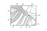
- FIG. 7 is an explanatory diagram for explaining an evaluation example of the flow of magnetic flux related to the electric motor according to the present embodiment.
- FIG. 8 is an explanatory diagram for explaining an evaluation example of the flow of magnetic flux related to the electric motor according to the comparative example.
- the center of curvature of the outer surface 23 p on the radially outer side of the magnet 23 is shifted from the rotation center Zr of the motor rotor 20.
- the center of curvature of the outer surface 23 p on the radially outer side of the magnet 23 coincides with the rotation center Zr of the motor rotor 20.
- the magnetic flux distribution in the region mf1 is made more uniform than in the region mf2.
- the rotor yoke 22 according to the present embodiment contributes to the reduction of torque ripple by controlling the magnetic flux as shown in FIG. 7 and controlling the flow of magnetic flux on the outer side surface 23p on the radially outer side of the magnet 23.
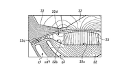
- FIG. 9 is an explanatory diagram illustrating an evaluation example of the flow of magnetic flux according to the electric motor according to the present embodiment.
- FIG. 10 is an explanatory diagram illustrating an evaluation example of the flow of magnetic flux related to the electric motor according to the comparative example.
- the rotor yoke 22 according to the present embodiment has a shape of the end mf3 on the outer side in the radial direction of the convex portions 22q of the magnetic gap portions g1 and g2, as shown in FIG. It is curved.
- the rotor yoke 22 according to the comparative example as shown in FIG.
- the shape of the end portion mf4 on the outer side in the radial direction of the convex portions 22q of the magnetic gap portions g1 and g2 is linear when viewed from the axial direction. is there.
- the end mf3 of the magnetic gap portions g1 and g2 on the radially outer side of the convex portion 22q according to the present embodiment shown in FIG. 9 is the convex portion of the magnetic gap portions g1 and g2 according to the comparative example shown in FIG.
- the magnetic flux is controlled so as to go from the rotor yoke 22 to the teeth 34 along the magnetic gap portions g1 and g2 rather than the end portion mf4 on the radially outer side of 22q.
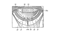
- FIG. 11 is an explanatory diagram for explaining an evaluation example of the flow of magnetic flux related to the electric motor according to the present embodiment.
- FIG. 12 is an explanatory diagram illustrating an evaluation example of the flow of magnetic flux related to the electric motor according to the comparative example.
- the rotor yoke 22 according to the present embodiment includes a convex magnetic gap part g ⁇ b> 1 (g ⁇ b> 2) and a convex magnetic gap part g ⁇ b> 1 (g ⁇ b> 2) adjacent in the circumferential direction in the radial direction. Extending so that the radially inner end is closer to the outer end, and the radially inner ends are spaced apart in a region mf5 that forms a magnetic path.
- the rotor yoke 22 according to the comparative example includes a magnetic gap portion g1 (g2) of a convex portion and a magnetic gap portion g1 (g2) of a convex portion adjacent in the circumferential direction.
- the ends on the radially inner side are closer to the ends on the radially outer side, and the ends on the radially inner side are close to each other in the region mf6.
- the magnetic resistance is larger than that in the region mf5, and the magnetic flux does not easily flow from the magnet 23 to the outside in the radial direction of the q axis of the convex portion.
- the magnetic gap portions g1 and g2 of the convex portion 22q and the magnetic gap portions g1 and g2 of the convex portion 22q adjacent in the circumferential direction have a diameter larger than the end portion on the radially outer side. Since the ends on the inner side in the direction extend so as to approach each other and the ends on the inner side in the radial direction have a magnetic path, the magnetic flux is transferred from the magnet 23 to the outer side in the radial direction of the q axis of the convex portion. It is controlled so as to go around from the tooth 34 to the tooth 34.
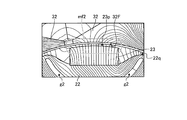
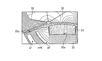
- FIG. 13 is an explanatory diagram for explaining an evaluation example of the flow of magnetic flux related to the electric motor according to the present embodiment.
- FIG. 14 is an explanatory diagram illustrating an evaluation example of the flow of magnetic flux related to the electric motor according to the comparative example.
- the rotor yoke 22 according to the present embodiment has a recess 22 d that is between the affixing surface 22 a on which the magnet 23 is disposed, and between the affixing surface 22 a and the protrusion 22 q, and is linear in the axial cross section. And an inclined portion 22b having a portion.
- the rotor yoke 22 according to the comparative example does not have a structure corresponding to the inclined portion 22b.
- the rotor yoke 22 according to the present embodiment has a gap in the circumferential area mf7 of the magnet 23, compared to the circumferential area mf8 of the magnet 23 according to the comparative example, so that the magnetic flux density as the q-axis of the convex portion is increased. It is possible to suppress the short circuit of the magnetic flux at the end of the magnet 23 and control the flow of the magnetic flux.
- FIG. 15 is a schematic diagram of a vehicle equipped with an electric power steering apparatus including the electric motor according to the present embodiment.
- the vehicle 100 is equipped with an electric power steering device 80 including the electric motor according to the above-described embodiment.
- the vehicle 100 may be equipped with the electric motor according to the present embodiment described above for uses other than the electric power steering device 80.
Landscapes
- Engineering & Computer Science (AREA)
- Power Engineering (AREA)
- Chemical & Material Sciences (AREA)
- Combustion & Propulsion (AREA)
- Transportation (AREA)
- Mechanical Engineering (AREA)
- Power Steering Mechanism (AREA)
- Permanent Field Magnets Of Synchronous Machinery (AREA)
- Iron Core Of Rotating Electric Machines (AREA)
Abstract
電動機(10)は、モータロータ(20)と、モータステータ(30)と、を備える。ロータヨーク(22)の外周は、ロータヨーク(22)の径方向外側に突出する凸部(22q)と、周方向に隣り合う凸部(22q)間の凹部(22d)と、を含む。マグネット(23)は、凹部(22d)表面である貼付面(22a)に配置されており、凸部(22q)には、軸方向に、ロータヨーク(22)の内部を貫通して、ロータヨーク(22)よりも透磁率が低く磁気的ギャップとなる磁気的ギャップ部(g1)、磁気的ギャップ部(g2)の少なくとも1つを備える。
Description
本発明は、電動機、電動パワーステアリング装置及び車両に関する。
例えば、特許文献1には、ロータ内部に永久磁石を埋め込む構造であり、マグネットトルクと、このマグネットトルクより小さいリラクタンストルクとを足しあわせたトルクを利用する永久磁石埋め込みモータ、いわゆるIPM(Interior Permanent Magnet)モータが記載されている。
近年、磁石の使用量を低減した電動機または磁石の希土類磁石成分を低減した電動機が求められるようになってきている。磁石の使用量を低減した電動機または磁石の希土類磁石成分を低減した電動機では、磁石が生じさせるマグネットトルクも低減する。そこで、ロータの表面に磁石を貼り合わせたSPM(Surface Permanent Magnet)モータにおいても、磁石の使用量や希土類成分含有量低減に伴うマグネットトルクを補うために、リラクタンストルクを利用できることが望まれている。
本発明は、上記に鑑みてなされたものであって、ロータヨークの外周に設けられて、ロータヨークの周方向に向かって配列される複数のマグネットを備え、d軸インダクタンスと、q軸インダクタンスの比である突極比を高め、リラクタンストルクを利用することができる電動機、電動パワーステアリング装置及び車両を提供することを目的とする。
上述した課題を解決し、目的を達成するために、電動機は、ロータヨークと、前記ロータヨークの外周に設けられて、前記ロータヨークの周方向に向かって配列される複数のマグネットと、を含むモータロータと、前記ロータヨークの径方向外側に、環状に配置されるステータコア及び前記ステータコアを励磁させる励磁コイルを含むモータステータと、を含み、前記ロータヨークの外周は、前記ロータヨークの径方向外側に突出する凸部と、周方向に隣り合う前記凸部間の凹部と、を含み、前記マグネットは、前記凹部表面に配置されている。
上記構成により、d軸インダクタンスと、q軸インダクタンスの比である突極比を高め、リラクタンストルクを利用することができる。また、トルクリップルが抑制され、電動機は制御性が向上する。
前記凸部には、前記モータロータの回転中心の軸と平行な軸方向に、前記ロータヨークの内部を貫通して、前記ロータヨークよりも透磁率が低く磁気的ギャップ部が少なくとも1つあることが好ましい。これにより、d軸インダクタンスと、q軸インダクタンスの比である突極比を高めることができる。
前記マグネットは、径方向外側の外径の曲率中心が前記モータロータの回転中心とずれていることが好ましい。この構造により、マグネットの径方向外側の外径磁束の流れをコントロールすることで、トルクリップルの低減に寄与する。
本発明の望ましい態様として、前記磁気的ギャップ部は、前記凸部の径方向外側寄りの端部の形状が軸方向からみて湾曲していることが好ましい。この構造により、凸部のq軸としての磁束の流れが凸部の径方向外側寄りの端部を回り込むように制御される。
本発明の望ましい態様として、前記凸部の磁気的ギャップ部と、周方向に隣り合う前記凸部の磁気的ギャップ部とは、径方向外側の端部よりも径方向内側の端部が近づくように延び、かつ当該径方向内側の端部同士が磁路となる間隔を有している。この構造により、マグネットより凸部のq軸の径方向外側まで磁束の流れが回り込むように制御される。
本発明の望ましい態様として、前記凹部は、前記マグネットが配置される前記凹部表面と、前記凸部の最外周との間に、軸方向でみて直線状の傾斜部を備えていることが好ましい。この構造により、マグネット両端部の周方向に空隙を有することで、マグネットの磁束が凸部のq軸への回り込みを制御することができ、トルク変動を低減できる。
本発明の望ましい態様として、前記磁気的ギャップ部は、前記軸方向でみた縁の少なくとも一部が、前記マグネットが配置される前記凹部表面よりも、前記ステータコア寄りにある仮想中心で描いた円弧を含むことが好ましい。
本発明の望ましい態様として、前記磁気的ギャップ部は、非磁性材料を含むことが好ましい。この構造により、ロータヨークの剛性を高めることができる。本発明の態様として、磁気的ギャップ部が空隙であってもよいが、ロータヨーク内に多くの空隙を穿つことは、ロータヨークの剛性を低減させる可能性がある。このため、磁気的ギャップ部は、磁気回路的に空気と等価な非磁性材料を内部に充填することで、ロータヨークの剛性を高めることができる。
本発明の望ましい態様として、上述した電動機は、補助操舵トルクを得るための電動パワーステアリング用途に用いられることが好ましい。また、本発明の望ましい態様として、前記電動機により補助操舵トルクを得る電動パワーステアリング装置であることが好ましい。また、本発明の望ましい態様として、前記電動機を備える車両であることが好ましい。
上記構成により、磁石の使用量を低減した電動機または磁石の希土類磁石成分を低減した電動機でも、十分なトルクを得ることができ、コストを抑制できる。また、ステータコアで生じる磁区が向きを変えるときのヒステリシス損が緩和される。ヒステリシス損は、電動機が空回りした場合のロストルクの増加の要因と考えられる。つまり、突発的な停止でも、電動機のロータが空回りした場合のロストルクの増加(電磁ブレーキ)を抑制することができる。ロストルクを抑制することができるので、電動パワーステアリング装置は、操舵者に補助操舵トルクが伝達されても違和感を抑制した状態で、動作することができる。
本発明によれば、ロータヨークの外周に設けられて、ロータヨークの周方向に向かって配列される複数のマグネットを備え、d軸インダクタンスと、q軸インダクタンスの比である突極比を高め、リラクタンストルクを利用することができる電動機及び電動パワーステアリング装置を提供することができる。
本発明を実施するための形態(実施形態)につき、図面を参照しつつ詳細に説明する。以下の実施形態に記載した内容により本発明が限定されるものではない。また、以下に記載した構成要素には、当業者が容易に想定できるもの、実質的に同一のものが含まれる。さらに、以下に記載した構成要素は適宜組み合わせることが可能である。
(電動パワーステアリング装置)
図1は、本実施形態に係る電動機を備える電動パワーステアリング装置の構成図である。本実施形態は、図1を用いて、電動機10を備える電動パワーステアリング装置80の概要を説明する。
図1は、本実施形態に係る電動機を備える電動パワーステアリング装置の構成図である。本実施形態は、図1を用いて、電動機10を備える電動パワーステアリング装置80の概要を説明する。
電動パワーステアリング装置80は、操舵者から与えられる力が伝達する順に、ステアリングホイール81と、ステアリングシャフト82と、操舵力アシスト機構83と、ユニバーサルジョイント84と、ロアシャフト85と、ユニバーサルジョイント86と、ピニオンシャフト87と、ステアリングギヤ88と、タイロッド89とを備える。また、電動パワーステアリング装置80は、ECU(Electronic Control Unit)90と、トルクセンサ91aと、車速センサ91bとを備える。
ステアリングシャフト82は、入力軸82aと、出力軸82bとを含む。入力軸82aは、一方の端部がステアリングホイール81に連結され、他方の端部がトルクセンサ91aを介して操舵力アシスト機構83に連結される。出力軸82bは、一方の端部が操舵力アシスト機構83に連結され、他方の端部がユニバーサルジョイント84に連結される。本実施形態では、入力軸82a及び出力軸82bは、鉄等の磁性材料から形成される。
ロアシャフト85は、一方の端部がユニバーサルジョイント84に連結され、他方の端部がユニバーサルジョイント86に連結される。ピニオンシャフト87は、一方の端部がユニバーサルジョイント86に連結され、他方の端部がステアリングギヤ88に連結される。
ステアリングギヤ88は、ピニオン88aと、ラック88bとを含む。ピニオン88aは、ピニオンシャフト87に連結される。ラック88bは、ピニオン88aに噛み合う。ステアリングギヤ88は、ラックアンドピニオン形式として構成される。ステアリングギヤ88は、ピニオン88aに伝達された回転運動をラック88bで直進運動に変換する。タイロッド89は、ラック88bに連結される。
操舵力アシスト機構83は、減速装置92と、電動機10とを含む。減速装置92は、出力軸82bに連結される。電動機10は、減速装置92に連結され、かつ、補助操舵トルクを発生させる電動機である。なお、電動パワーステアリング装置80は、ステアリングシャフト82と、トルクセンサ91aと、減速装置92とによりステアリングコラムが構成されている。電動機10は、ステアリングコラムの出力軸82bに補助操舵トルクを与える。すなわち、本実施形態の電動パワーステアリング装置80は、コラムアシスト方式である。
コラムアシスト方式の電動パワーステアリング装置80は、操作者と電動機10との距離が比較的近く、電動機10のトルク変化又は摩擦力が操舵者に影響を与えるおそれがある。このため、電動パワーステアリング装置80では、電動機10の摩擦力の低減が求められる。
図2は、本実施形態の電動パワーステアリング装置が備える減速装置の一例を説明する正面図である。図2は、一部を断面として示してある。減速装置92はウォーム減速装置である。減速装置92は、減速装置ハウジング93と、ウォーム94と、玉軸受95aと、玉軸受95bと、ウォームホイール96と、ホルダ97とを備える。
ウォーム94は、電動機10のシャフト21にスプライン、または弾性カップリングで結合する。ウォーム94は、玉軸受95aと、ホルダ97に保持された玉軸受95bとで回転自在に減速装置ハウジング93に保持されている。ウォームホイール96は、減速装置ハウジング93に回転自在に保持される。ウォーム94の一部に形成されたウォーム歯94aは、ウォームホイール96に形成されているウォームホイール歯96aに噛み合う。
電動機10の回転力は、ウォーム94を介してウォームホイール96に伝達されて、ウォームホイール96を回転させる。減速装置92は、ウォーム94及びウォームホイール96によって、電動機10のトルクを増加する。そして、減速装置92は、図1に示すステアリングコラムの出力軸82bに補助操舵トルクを与える。
図1に示すトルクセンサ91aは、ステアリングホイール81を介して入力軸82aに伝達された運転者の操舵力を操舵トルクとして検出する。車速センサ91bは、電動パワーステアリング装置80が搭載される車両の走行速度を検出する。ECU90は、電動機10と、トルクセンサ91aと、車速センサ91bとが電気的に接続される。
ECU90は、電動機10の動作を制御する。また、ECU90は、トルクセンサ91a及び車速センサ91bのそれぞれから信号を取得する。すなわち、ECU90は、トルクセンサ91aから操舵トルクTを取得し、かつ、車速センサ91bから車両の走行速度Vを取得する。ECU90は、イグニッションスイッチ98がオンの状態で、電源装置(例えば車載のバッテリ)99から電力が供給される。ECU90は、操舵トルクTと走行速度Vとに基づいてアシスト指令の補助操舵指令値を算出する。そして、ECU90は、その算出された補助操舵指令値に基づいて電動機10へ供給する電力値Xを調節する。ECU90は、電動機10から誘起電圧の情報又は後述するレゾルバからロータの回転の情報を動作情報Yとして取得する。
ステアリングホイール81に入力された操舵者(運転者)の操舵力は、入力軸82aを介して操舵力アシスト機構83の減速装置92に伝わる。この時に、ECU90は、入力軸82aに入力された操舵トルクTをトルクセンサ91aから取得し、かつ、走行速度Vを車速センサ91bから取得する。そして、ECU90は、電動機10の動作を制御する。電動機10が作り出した補助操舵トルクは、減速装置92に伝えられる。
出力軸82bを介して出力された操舵トルクT(補助操舵トルクを含む)は、ユニバーサルジョイント84を介してロアシャフト85に伝達され、さらにユニバーサルジョイント86を介してピニオンシャフト87に伝達される。ピニオンシャフト87に伝達された操舵力は、ステアリングギヤ88を介してタイロッド89に伝達され、操舵輪を転舵させる。次に、電動機10について説明する。
(電動機)
図3は、中心軸を含む仮想平面で本実施形態の電動機の構成を切って模式的に示す断面図である。図4は、本実施形態の電動機の構成を中心軸に直交する仮想平面で切って模式的に示す断面図である。図3に示すように、電動機10は、ハウジング11と、軸受12と、軸受13と、レゾルバ14と、モータロータ20と、ブラシレスモータ用としてのモータステータ30とを備える。
図3は、中心軸を含む仮想平面で本実施形態の電動機の構成を切って模式的に示す断面図である。図4は、本実施形態の電動機の構成を中心軸に直交する仮想平面で切って模式的に示す断面図である。図3に示すように、電動機10は、ハウジング11と、軸受12と、軸受13と、レゾルバ14と、モータロータ20と、ブラシレスモータ用としてのモータステータ30とを備える。
ハウジング11は、筒状ハウジング11aと、フロントブラケット11bとを含む。フロントブラケット11bは、略円板状に形成されて筒状ハウジング11aの一方の開口端部を閉塞するように筒状ハウジング11aに取り付けられる。筒状ハウジング11aは、フロントブラケット11bとは反対側の端部に、この端部を閉塞するように底部11cが形成される。底部11cは、例えば、筒状ハウジング11aと一体に形成される。筒状ハウジング11aを形成する材料としては、例えばSPCC(Steel Plate Cold Commercial)等の一般的な鋼材や、電磁軟鉄、アルミニウム等が適用できる。また、フロントブラケット11bは、電動機10を所望の機器に取り付ける際のフランジの役割を果たしている。
軸受12は、筒状ハウジング11aの内側であって、フロントブラケット11bの略中央部分に設けられる。軸受13は、筒状ハウジング11aの内側であって、底部11cの略中央部分に設けられる。軸受12は、筒状ハウジング11aの内側に配置されたモータロータ20の一部であるシャフト21の一端を回転可能に支持する。軸受13は、シャフト21の他端を回転可能に支持する。これにより、シャフト21は、回転中心Zrの軸を中心に回転する。
レゾルバ14は、シャフト21のフロントブラケット11b側に設けられる端子台15によって支持される。レゾルバ14は、モータロータ20(シャフト21)の回転位置を検出する。レゾルバ14は、レゾルバロータ14aと、レゾルバステータ14bとを備える。レゾルバロータ14aは、シャフト21の円周面に圧入等で取り付けられる。レゾルバステータ14bは、レゾルバロータ14aに所定間隔の空隙を介して対向して配置される。
モータステータ30は、筒状ハウジング11aの内部にモータロータ20を包囲するように筒状に設けられる。モータステータ30は、筒状ハウジング11aの内周面11dに例えば嵌合されて取り付けられる。モータステータ30の中心軸は、モータロータ20の回転中心Zrと一致する。モータステータ30は、筒状のステータコア31と、励磁コイル37とを含む。モータステータ30は、ステータコア31に励磁コイル37が巻きつけられる。
図4に示すように、ステータコア31は、複数のティース34を含む。本実施形態のティース34は、周方向に9ある。ステータコア31は、略同形状に形成された複数のコア片が回転中心Zrの軸と平行な軸方向に積層されて束ねられることで形成される。ティース34の内周側には、ティース先端32が周方向に突出しており、ティース34の内周表面32Fがロータヨーク22の外周とギャップGの間隔を介して対向する。ステータコア31は、電磁鋼板などの磁性材料で形成される。ステータコア31は、バックヨーク33と、ティース34とを有する。バックヨーク33は、円弧状の部分を含む。バックヨーク33は、環状形状である。ティース34は、バックヨーク33の内周面からモータロータ20に向かって延びる部分である。
複数のティース34は、回転中心Zrを中心とした周方向(図3、図4に示す筒状ハウジング11aの内周面11dに沿う方向)に等間隔で並んで配置される。以下、回転中心Zrを中心とした周方向を単に周方向という。そして、ステータコア31が筒状ハウジング11a内に圧入されることで、モータステータ30は、環状の状態で筒状ハウジング11aの内部に設けられる。なお、ステータコア31と筒状ハウジング11aとは、圧入の他に接着、焼き嵌め又は溶接等によって固定されてもよい。
図4に示す励磁コイル37は、線状の電線である。励磁コイル37は、ティース34の外周にインシュレータ37a(図3参照)を介して集中巻きされる。この構成により、磁極数を低減でき、かつ分布巻きに比較してコイルエンドが短くなることからコイル量を低減できる。その結果、コストを低減でき、電動機10をコンパクトにすることができる。
励磁コイル37は、ティース34の複数の外周に分布巻きされていてもよい。この構成により、磁極数が増え、磁束の分布が安定することからトルクリップルを抑制することができる。
励磁コイル37は、バックヨーク33の外周にトロイダル巻きされていてもよい。この構成により、分布巻きと同等の磁束分布を発生すると共に、分布巻きに比較してコイルエンドが短くなることからコイル量を低減できる。その結果、トルクリップルを抑制すると共に、電動機10をコンパクトにすることができる。
図3に示すインシュレータ37aは、励磁コイル37とステータコア31とを絶縁するための部材であり、耐熱部材で形成される。また、モータステータ30は、モータロータ20を包囲できる形状となる。つまり、ステータコア31は、後述するロータヨーク22の径方向外側に所定の間隔(ギャップ)Gを有して環状に配置される。
モータロータ20は、筒状ハウジング11aに対して回転中心Zrを中心に回転できるように、筒状ハウジング11aの内部に設けられる。モータロータ20は、シャフト21と、ロータヨーク22と、マグネット23とを含む。シャフト21は、筒状に形成される。ロータヨーク22は、筒状に形成される。なお、ロータヨーク22は、外周が円弧状である。この構成により、ロータヨーク22は、外周が複雑形状である場合に比較して、打ち抜き加工の加工工数を低減できる。
ロータヨーク22は、電磁鋼板、冷間圧延鋼板などの薄板が、接着、ボス、カシメなどの手段により積層されて製造される。ロータヨーク22は、順次金型の型内で積層され、金型から排出される。ロータヨーク22は、例えばその中空部分にシャフト21が圧入されてシャフト21に固定される。なお、シャフト21とロータヨーク22とは、一体で成型されてもよい。
マグネット23は、ロータヨーク22の周方向に沿って表面に固定され、複数設けられている。マグネット23は、永久磁石であり、S極及びN極がロータヨーク22の周方向に交互に等間隔で配置される。これにより、図4に示すモータロータ20の極数は、ロータヨーク22の外周側にN極と、S極とがロータヨーク22の周方向に交互に配置された6極である。
図5は、本実施形態のモータロータの構成を模式的に示す説明図である。図4及び図5に示すように、ロータヨーク22の外周は、ロータヨーク22の径方向外側に突出する凸部22qと、周方向に隣り合う凸部22q間の凹部22dと、を含む。このように、ロータヨーク22の外周は、凸部22qと、凹部22dとが周方向に交互に配置されている。
凸部22qには、モータロータ20の回転中心Zrと平行な軸方向(以下、軸方向という。)に、ロータヨーク22に空けられた貫通孔が磁気的ギャップ部g1、磁気的ギャップ部g2として備えられている。磁気的ギャップ部g1、磁気的ギャップ部g2は、ロータヨーク22を貫通して、ロータヨーク22の透磁率よりも透磁率の低い、空隙である。磁気的ギャップとして、磁気的ギャップ部g1、磁気的ギャップ部g2は、磁束の通過を抑制又は遮断できる。磁気的ギャップ部g1、磁気的ギャップ部g2は、熱硬化性樹脂などの非磁性材料を充填して、非磁性材料を含むようにしてもよい。この構造により、ロータヨーク22の剛性を確保することができる。
マグネット23は、ロータヨーク22の凹部22dに収容され、例えば、磁力により取り付けられる。本実施形態では、マグネット23は、ロータヨーク22の周方向に沿って表面に固定され、複数設けられている分割形状(セグメント構造)のセグメント磁石である。
マグネット23は、軸方向の断面が、いわゆるカマボコ形状である。ロータヨーク22の凹部22dは、マグネット23が配置される貼付面22aと、貼付面22aと凸部22qとの間にあって軸方向の断面に直線状の部分を有する傾斜部22bとを備える。マグネット23の軸方向の断面が、径方向内側の内側面23aと、周方向の端面23b、23cと、径方向外側の外側面23pである場合、径方向内側の内側面23aは、貼付面22aと面接触する。貼付面22aは、凸部22qの最外径表面の周方向円弧が有する曲率半径r23よりも回転中心Zrを中心とした曲率半径r22が小さい。径方向外側の外側面23pは、凸部22qの最外径表面の周方向円弧と同程度の曲率半径r23を有している。また、ティース34の内周表面32Fとロータヨーク22の外周とのギャップGの間隔のうち、ギャップG2が周方向の端面23b、23cと、傾斜部22bと、ティース34の内周表面32Fとで囲まれる空間となる。
図4及び図5に示すように、ロータヨーク22の外周側にN極が着磁されているマグネット23と、ロータヨーク22の外周側にS極が着磁されているマグネット23とは、ロータヨーク22の周方向に交互に等間隔で配置される。そして、マグネット23は、径方向外側の外側面23pの曲率が凹部22dの貼付面22aの曲率とは異なるようになっている。
本実施形態に係る電動機10は、ロータヨーク22の凸部22qに、磁気的ギャップ部g1、磁気的ギャップ部g2を備えることで、ロータヨーク22の外周に磁気抵抗の差が生じる。凸部22qの磁気的ギャップ部g1と、周方向に隣り合う凸部22qの磁気的ギャップ部g1とは、径方向外側の端部g1eb同士よりも径方向内側の端部g1ea同士が近づくように延び、かつ当該径方向内側の端部g1ea間には磁路となる間隔md1、md2を有している。凸部22qの磁気的ギャップ部g2と、周方向に隣り合う凸部22qの磁気的ギャップ部g2とは、径方向外側の端部g2eb同士よりも径方向内側の端部g2ea同士が近づくように延び、かつ当該径方向内側の端部g2eaが磁路となる間隔md3を有している。回転中心Zrと、マグネット23の一部、例えば、外側面23pの周方向の仮想基準点grとを結ぶ仮想線gs上には、磁気的ギャップ部g1、磁気的ギャップ部g2がなく、磁束が通り易くなっている。凸部22qの磁気的ギャップ部g2と、周方向に隣り合う凸部22qの磁気的ギャップ部g2とは、仮想線gsに対して線対称の形状である。同様に、凸部22qの磁気的ギャップ部g1と、周方向に隣り合う凸部22qの磁気的ギャップ部g1とは、仮想線gsに対して線対称の形状である。上述した間隔md1、md2、md3は、間隔md1、md2、md3の順に狭くなっている。
磁気的ギャップ部g1は、軸方向でみた縁の少なくとも一部が、マグネット23が配置される内側面23a(凹部表面)よりも、ステータコア31寄りにある仮想中心(本実施形態では仮想基準点gr)、曲率半径gr1で描いた円弧を含む。磁気的ギャップ部g2は、軸方向でみた縁の少なくとも一部が、マグネット23が配置される内側面23a(凹部表面)よりも、ステータコア31寄りにある仮想中心(本実施形態では仮想基準点gr)、曲率半径gr2で描いた円弧を含む。このため、ロータヨーク22は、磁気的ギャップ部g1と磁気的ギャップ部g2との間の距離gdがほぼ一定となり、磁気的ギャップ部g1と磁気的ギャップ部g2との間のロータヨーク22に磁束が流れるようになる。
モータロータ20は、磁気的ギャップ部g1、磁気的ギャップ部g2の径方向外側で磁束を通すブリッジ部22fを備えている。磁気的ギャップ部g1、磁気的ギャップ部g2は、径方向外側寄りの端部g1eb、g2ebの形状が軸方向からみて湾曲している。
ブリッジ部22fの径方向の厚みΔfは、磁気的ギャップ部g1の径方向外側寄りの端部g1ebの幅g1wbよりも小さい。同様に、ブリッジ部22fの径方向の厚みΔfは、磁気的ギャップ部g2の径方向外側寄りの端部g2ebの幅g2wbよりも小さい。この構造により、凸部22qの外縁の磁気抵抗が、ブリッジ部22fで高くなり、ブリッジ部22fは、凸部22qの外周の磁束の流れを制限することができる。ブリッジ部22fの径方向の厚みΔfでの磁気抵抗を高めることで、隣合う、磁気的ギャップ部g1と磁気的ギャップ部g2との間のロータヨーク22(距離gd)内を流れる磁束の短絡を抑制できる。また、ブリッジ部22fの径方向の厚みΔfでの磁気抵抗を高めることで、隣合うティース34間で磁束を短絡させる経路となるのを抑制できる。
磁気的ギャップ部g1は、磁気的ギャップ部g2よりも、回転中心Zr寄りに配置されている。磁気的ギャップ部g2において、径方向外側の端部g2ebの幅g2wbは、径方向内側の端部g2eaの幅g2waと同程度である。これに対して、磁気的ギャップ部g1において、径方向内側の端部g1eaの幅g1waは、径方向外側の端部g1ebの幅g1wbよりも広くなっている。
磁気的ギャップ部g1は、径方向外側の端部同士が幅geの磁路を残して、回転中心Zrから径方向外側へ向かって併走するように延びている。このように、磁気的ギャップ部g1は、径方向外側の端部同士が幅geの磁路を残して、磁気的ギャップ部g1間にロータヨーク22の磁性体が残っている状態である。本実施形態の磁気的ギャップ部g1は、この態様に限られず、隣合う磁気的ギャップ部g1の径方向外側の端部で隣合う磁気的ギャップ部g1間のロータヨーク22の磁性体がなくなり磁気的ギャップ部が一体化していてもよい。
このため、ロータヨーク22の外周には、凸部22qとマグネット23とが交互に配置されている。マグネット23は、形状としてロータヨーク22の径方向外側に突出する凸部であり、磁気抵抗が大きくインダクタンスが小さい磁気的凸部である。磁気的凸部であるマグネット23がd軸と呼ばれ、これと磁気的に電気角で90°位相が異なる位置をq軸と呼び、マグネット23より周方向両側の磁路形成により、凸部22qが、磁気抵抗が小さくインダクタンスが大きい磁気的凹部となる。ステータコア31と、ロータヨーク22との所定の間隔であるギャップGは、ロータヨーク22の回転に伴い、ギャップG1、G2、G3、G2、G1の順に入れ替わり変化する。
マグネット23がロータヨーク22の表面に固定され、凸部22qに、磁気的ギャップ部g1、磁気的ギャップ部g2による磁路回路を構成することにより、下記式(1)に示すように、モータロータ20の平均トルクTtは、マグネット23のマグネットトルクTmに加え、ロータヨーク22の外周に生じる磁気的凹凸によるリラクタンストルクTrが生じる。その結果、ロータヨーク22からステータコア31へ鎖交する磁束が低減してもモータロータ20に生じる平均トルクTtは向上する。
Tt=Tr+Tm・・・(1)
本実施形態に係る電動機10は、モータロータ20と、モータステータ30と、を備える。モータロータ20は、ロータヨーク22と、ロータヨーク22の外周に設けられて、ロータヨーク22の周方向に向かって配列される複数のマグネット23と、を含む。モータステータ30は、ロータヨーク22の径方向外側に、環状に配置されるステータコア31及びステータコア31を励磁させる励磁コイル37を含む。そして、ロータヨーク22の外周は、ロータヨーク22の径方向外側に突出する凸部22qと、周方向に隣り合う凸部22q間の凹部22dと、を含む。マグネット23は、凹部22d表面である貼付面22aに配置されており、凸部22qには、軸方向に、ロータヨーク22の内部を貫通して、ロータヨーク22よりも透磁率が低く磁気的ギャップとなる磁気的ギャップ部g1、磁気的ギャップ部g2の少なくとも1つを備える。
この構造により、リラクタンストルクが作用してq軸インダクタンスが高まり、d軸インダクタンスに対するq軸インダクタンスの比である突極比が大きくなる。これにより、磁石の使用量を低減した電動機または磁石の希土類磁石成分を低減し、磁石が生じさせるマグネットトルクが小さくても、リラクタンストルクを利用して、モータロータ20の平均トルクTtを確保することができる。このように、磁石の使用量を低減した電動機または磁石の希土類磁石成分を低減した電動機でも、十分なトルクを得ることができ、コストを抑制できる。また、ステータコアで生じる磁区が向きを変えるときのヒステリシス損が緩和される。ヒステリシス損は、電動機が空回りした場合のロストルクの増加の要因と考えられる。つまり、突発的な停止でも、電動機のロータが空回りした場合のロストルクの増加(電磁ブレーキ)を抑制することができる。ロストルクを抑制することができるので、電動パワーステアリング装置は、操舵者に補助操舵トルクが伝達されても違和感を抑制した状態で、動作することができる。
電動パワーステアリング装置80は、上述した電動機10により補助操舵トルクを得る。電動パワーステアリング装置80は、電動機10がロストルクを抑制しているので、操舵者が違和感を抑制した状態で、動作することができる。このため、電動パワーステアリング装置80は、コラムアシスト方式であっても、低振動とすることができる。なお、本実施形態の電動パワーステアリング装置80は、コラムアシスト方式を例にして説明しているが、ピニオンアシスト方式及びラックアシスト方式についても適用することができる。
(ダイレクトドライブモータ)
本実施形態の電動機は、モータロータ20と、モータロータ20が回転させる負荷体とを直結しているダイレクトドライブモータとしても使用できる。図6は、本実施形態に係る電動機をダイレクトドライブモータとして適用した場合の説明図である。なお、上述した実施形態で説明したものと同じ構成要素には同一の符号を付して重複する説明は省略する。
本実施形態の電動機は、モータロータ20と、モータロータ20が回転させる負荷体とを直結しているダイレクトドライブモータとしても使用できる。図6は、本実施形態に係る電動機をダイレクトドライブモータとして適用した場合の説明図である。なお、上述した実施形態で説明したものと同じ構成要素には同一の符号を付して重複する説明は省略する。
図6に示すように、電動機10Aは、ギヤ、ベルトまたはローラ等の伝達機構を介在させることなく負荷体52に回転力をダイレクトに伝達し、負荷体52を回転させることができる。電動機10Aは、いわゆるモータ回転軸60と負荷体52とをボルトなどの固定部材67で直結したダイレクトドライブモータである。
電動機10Aは、静止状態に維持されるモータステータ30と、モータステータ30に対して回転可能に配置されたモータロータ20と、モータステータ30を固定して支持部材51に取り付けられるベース部材70と、モータロータ20に固定されてモータロータ20と共に回転可能なモータ回転軸60と、ベース部材70とモータ回転軸60との間に介在されてモータ回転軸60をベース部材70に対して回転可能に支持する軸受64と、を含む。
ベース部材70、モータ回転軸60、モータロータ20及びモータステータ30はいずれも環状の構造体である。モータ回転軸60、モータロータ20及びモータステータ30は、回転中心Zrを中心に同心状に配置されている。また、電動機10Aは、回転中心Zrから外側へモータロータ20、モータステータ30の順に配置されている。このような電動機10Aは、インナーロータ型と呼ばれ、モータロータ20がモータステータ30よりも回転中心Zr寄りとなる。また、電動機10Aは、モータ回転軸60、モータロータ20及びモータステータ30がベース部材70の上に配置されている。
ベース部材70は、略円板状のハウジングベース71と、中空部61が貫通し、中空部61を囲むようにハウジングベース71から凸状に突出した軸心となるハウジングインナ72を備えている。ハウジングインナ72は、ハウジングベース71にボルト等の固定部材77を介して締結され固定されている。また、ベース部材70は、ボルト等の固定部材76を介してハウジングベース71に軸受64の内輪を固定するハウジングフランジ73を含む。
ハウジングベース71の外周縁には、モータステータ30がボルト等の固定部材78によって締結されている。これにより、モータステータ30はハウジングベース71に対して位置決め固定されている。モータステータ30の中心軸は、モータロータ20の回転中心Zrと一致する。
モータステータ30は、筒状のステータコア31と、励磁コイル37とを含む。モータステータ30は、ステータコア31に励磁コイル37が巻きつけられる。モータステータ30には、電源からの電力を供給するための配線(図示しない)が接続されており、この配線を通じて励磁コイル37に対して電力が供給されるようになっている。
モータロータ20は、モータロータ20の外径がモータステータ30の内径寸法よりも小さな円筒状である。モータロータ20は、ロータヨーク22及びロータヨーク22の外周に貼り付けられたマグネット23を含む。
モータ回転軸60は、円環状の回転軸62と、ボルト等の固定部材66を介して回転軸62に軸受64の外輪を固定するロータフランジ63とを含む。モータロータ20は、円筒状のモータ回転軸60の回転軸62に一体的に固定されている。モータロータ20は、円筒状のモータ回転軸60の回転軸62に固定部材により固定されてもよい。回転軸62は、円環の中心軸が電動機10Aの回転中心Zrと同軸に形成されている。
また、軸受64は、外輪がロータフランジ63に固定され、内輪がハウジングフランジ73に固定されている。これにより、軸受64は、ハウジングベース71に対して、回転軸62及びモータロータ20を回転自在に支持することができる。このため、電動機10Aは、回転軸62及びモータロータ20をハウジングベース71及びモータステータ30に対して回転させることができる。
なお、軸受64は、転動体をクロスローラとしたクロスローラ軸受としてもよい。なお、軸受64は、クロスローラ軸受に限定されず、例えば転動体を玉やころ(円筒ころ、円錐ころ、球面ころなど)とした玉軸受やころ軸受としてもよい。これらの転動体は、環状を成す保持器のポケットに1つずつ所定間隔、例えば等間隔で配列し、このポケット内で回転自在に保持された状態で軌道面間に組み込んでもよい。これにより、各転動体は所定間隔を保った状態で、その転動面が相互に接触することなく、上記軌道面間を転動することができる。また、各転動体は、相互に接触して摩擦が生じることによる回転抵抗の増大や、焼付きなどを防止することができる。
また、電動機10Aは、回転検出器を備える。回転検出器は、例えばレゾルバであって、モータロータ20及びモータ回転軸60の回転位置を高精度に検出することができる。回転検出器は、静止状態に維持されるレゾルバステータ14bと、レゾルバステータ14bと所定のギャップを隔てて対向配置され、レゾルバステータ14bに対して回転可能なレゾルバロータ14aを備えており、軸受64の上方に配設されている。
レゾルバステータ14bは、複数のステータ磁極が円周方向に等間隔に形成された環状の積層鉄心を有し、各ステータ磁極にレゾルバコイルが巻回されている。本実施形態の電動機10Aでは、レゾルバステータ14bは、ハウジングインナ72に固定されている。
レゾルバロータ14aは、中空環状の積層鉄心により構成されており、モータ回転軸60の内側に固定されている。回転検出器の配設位置は、モータロータ20(モータ回転軸60)の回転を検出することが可能であれば特に限定されず、モータ回転軸60及びベース部材70の形状に応じて任意の位置へ配設することができる。
モータロータ20が回転すると、モータロータ20と共にモータ回転軸60が回転し、連動してレゾルバロータ14aも回転する。これにより、レゾルバロータ14aと、レゾルバステータ14bとの間のリラクタンスが連続的に変化する。レゾルバステータ14bは、リラクタンスの変化を検出し、レゾルバ制御回路によって電気信号(デジタル信号)に変換する。電動機10Aを制御する制御装置は、レゾルバ制御回路の電気信号に基づいて、単位時間当たりのレゾルバロータ14aと連動するモータ回転軸60及びモータロータ20の位置や回転角度を演算処理することができる。その結果、電動機10Aを制御する制御装置は、モータ回転軸60の回転状態(例えば、回転速度、回転方向あるいは回転角度など)を計測することが可能となる。
このように、電動機10Aは、モータロータ20の1回転につき、リラクタンス変化の基本波成分の周期が異なる複数の回転検出器を備えることにより、モータ回転軸60の絶対位置を把握することができ、また、モータ回転軸60の回転状態(例えば、回転速度、回転方向あるいは回転角度など)を計測する精度を高めることができる。
電動機10Aは、ハウジングベース71が支持部材51に取り付けられることで、支持部材51に対して位置決め固定される。ハウジングベース71は、支持部材51に取り付けられた状態において、支持部材51の取付面と接する一連の連続面を少なくとも1つ有している。この連続面は、電動機10Aの自重や回転時の振動などを支持部材51に分散して作用させることができる。このため、ハウジングベース71に歪み(撓み)が生ずるおそれを防止することができる。
以上説明したように、電動機10Aは、伝達機構を介在させることなく負荷体52に回転力をダイレクトに伝達できる。このため、負荷体52を回転させる場合、電動機10Aは、モータトルクを高めることができる。
(評価例)
以下、本実施形態に係る電動機に係る磁束の流れについて、図7から図14を用いて、比較例と比較しながら説明する。図7から図14には、上述した実施形態で説明したものと同じ構成要素には同一の符号を付して、磁束分布と重ね合わせて表示し、同一の符号を付して重複する説明は省略する。
以下、本実施形態に係る電動機に係る磁束の流れについて、図7から図14を用いて、比較例と比較しながら説明する。図7から図14には、上述した実施形態で説明したものと同じ構成要素には同一の符号を付して、磁束分布と重ね合わせて表示し、同一の符号を付して重複する説明は省略する。
図7は、本実施形態に係る電動機に係る磁束の流れの評価例を説明する説明図である。図8は、比較例に係る電動機に係る磁束の流れの評価例を説明する説明図である。本実施形態に係るロータヨーク22は、図7に示すように、マグネット23の径方向外側の外側面23pの曲率中心がモータロータ20の回転中心Zrとずれている。これに対して、比較例に係るロータヨーク22は、図8に示すように、マグネット23の径方向外側の外側面23pの曲率中心がモータロータ20の回転中心Zrと一致している。図7に示すティース34の内周表面32Fとマグネット23の径方向外側の外側面23pとの対向領域mf1と、図8に示すティース34の内周表面32Fとマグネット23の径方向外側の外側面23pとの対向領域mf2とを比較する場合、領域mf1は、領域mf2よりも磁束の分布が均一化される。このため、本実施形態に係るロータヨーク22は、図7に示すように磁束を制御し、マグネット23の径方向外側の外側面23pの磁束の流れをコントロールすることでトルクリップルの低減に寄与する。
図9は、本実施形態に係る電動機に係る磁束の流れの評価例を説明する説明図である。図10は、比較例に係る電動機に係る磁束の流れの評価例を説明する説明図である。図9に示すように、本実施形態に係るロータヨーク22は、図9に示すように、磁気的ギャップ部g1、g2の凸部22qの径方向外側寄りの端部mf3の形状が軸方向からみて湾曲している。これに対して、比較例に係るロータヨーク22は、図10に示すように、磁気的ギャップ部g1、g2の凸部22qの径方向外側寄りの端部mf4の形状が軸方向からみて直線状である。図9に示す本実施形態に係る、磁気的ギャップ部g1、g2の凸部22qの径方向外側寄りの端部mf3は、図10に示す比較例に係る磁気的ギャップ部g1、g2の凸部22qの径方向外側寄りの端部mf4よりも磁束が磁気的ギャップ部g1、g2に沿ってロータヨーク22からティース34へ回り込むように制御される。
図11は、本実施形態に係る電動機に係る磁束の流れの評価例を説明する説明図である。図12は、比較例に係る電動機に係る磁束の流れの評価例を説明する説明図である。本実施形態に係るロータヨーク22は、図11に示すように、凸部の磁気的ギャップ部g1(g2)と、周方向に隣り合う凸部の磁気的ギャップ部g1(g2)とが、径方向外側の端部よりも径方向内側の端部が近づくように延び、かつ径方向内側の端部同士が磁路となる領域mf5で間隔を有している。これに対して、比較例に係るロータヨーク22は、図12に示すように、凸部の磁気的ギャップ部g1(g2)と、周方向に隣り合う凸部の磁気的ギャップ部g1(g2)とが、径方向外側の端部よりも径方向内側の端部が近づくように延び、かつ径方向内側の端部同士が領域mf6で近接している。領域mf6は、領域mf5よりも磁気抵抗が大きく、マグネット23より凸部のq軸の径方向外側まで磁束の流れが回り込みにくい。本実施形態に係るロータヨーク22は、凸部22qの磁気的ギャップ部g1、g2と、周方向に隣り合う凸部22qの磁気的ギャップ部g1、g2とは、径方向外側の端部よりも径方向内側の端部が近づくように延び、かつ当該径方向内側の端部同士が磁路となる間隔を有しているので、マグネット23より凸部のq軸の径方向外側まで磁束がロータヨーク22からティース34へ回り込むように制御される。
図13は、本実施形態に係る電動機に係る磁束の流れの評価例を説明する説明図である。図14は、比較例に係る電動機に係る磁束の流れの評価例を説明する説明図である。本実施形態に係るロータヨーク22は、図13に示すように、凹部22dが、マグネット23が配置される貼付面22aと、貼付面22aと凸部22qとの間にあって軸方向の断面に直線状の部分を有する傾斜部22bとを備える。これに対して、比較例に係るロータヨーク22は、傾斜部22bに相当する構造がない。本実施形態に係るロータヨーク22は、マグネット23の周方向の領域mf7に、比較例に係るマグネット23の周方向の領域mf8よりも空隙を有することで、凸部のq軸としての磁束の密度を高め、かつマグネット23端部の磁束の短絡を抑制し、磁束の流れを制御することができる。
図15は、本実施形態に係る電動機を備える電動パワーステアリング装置を搭載した車両の模式図である。図15に示すように、車両100は、上述した本実施形態に係る電動機を備える電動パワーステアリング装置80を搭載している。車両100は、上述した本実施形態に係る電動機を電動パワーステアリング装置80以外の用途で搭載してもよい。
10、10A 電動機
11 ハウジング
11a 筒状ハウジング
11d 内周面
14 レゾルバ
20 モータロータ
21 シャフト
22 ロータヨーク
22a 貼付面
22b 傾斜部
22d 凹部
22f ブリッジ部
22q 凸部
23 マグネット
23a 内側面
23b、23c 端面
23p 外側面
30 モータステータ
31 ステータコア
32 ティース先端
33 バックヨーク
34 ティース
37 励磁コイル
37a インシュレータ
52 負荷体
60 モータ回転軸
61 中空部
62 回転軸
63 ロータフランジ
64 軸受
70 ベース部材
71 ハウジングベース
72 ハウジングインナ
73 ハウジングフランジ
80 電動パワーステアリング装置
g1、g2 磁気的ギャップ部
Zr 回転中心
Claims (11)
- ロータヨークと、前記ロータヨークの外周に設けられて、前記ロータヨークの周方向に向かって配列される複数のマグネットと、を含むモータロータと、
前記ロータヨークの径方向外側に、環状に配置されるステータコア及び前記ステータコアを励磁させる励磁コイルを含むモータステータと、
を含み、
前記ロータヨークの外周は、前記ロータヨークの径方向外側に突出する凸部と、周方向に隣り合う前記凸部間の凹部と、を含み、
前記マグネットは、前記凹部表面に配置されている電動機。 - 前記凸部には、前記モータロータの回転中心の軸と平行な軸方向に、前記ロータヨークの内部を貫通して、前記ロータヨークよりも透磁率が低く磁気的ギャップ部が少なくとも1つある、請求項1に記載の電動機。
- 前記マグネットは、径方向外側の外径の曲率中心が前記モータロータの回転中心とずれている、請求項1又は2に記載の電動機。
- 前記磁気的ギャップ部は、前記凸部の径方向外側寄りの端部の形状が軸方向からみて湾曲している、請求項1から3のいずれか1項に記載の電動機。
- 前記凸部の磁気的ギャップ部と、周方向に隣り合う前記凸部の磁気的ギャップ部とは、径方向外側の端部よりも径方向内側の端部が近づくように延び、かつ当該径方向内側の端部同士が磁路となる間隔を有している、請求項1から4のいずれか1項に記載の電動機。
- 前記凹部は、前記マグネットが配置される前記凹部表面と、前記凸部の最外周との間に、軸方向でみて直線状の傾斜部を備えている、請求項1から5のいずれか1項に記載の電動機。
- 前記磁気的ギャップ部は、前記軸方向でみた縁の少なくとも一部が、前記マグネットが配置される前記凹部表面よりも、前記ステータコア寄りにある仮想中心で描いた円弧を含む、請求項1から6のいずれか1項に記載の電動機。
- 前記磁気的ギャップ部は、非磁性材料を含む、請求項1から7のいずれか1項に記載の電動機。
- 補助操舵トルクを得るための電動パワーステアリング用途に用いられる、請求項1から8のいずれか1項に記載の電動機。
- 請求項1から8のいずれか1項に記載の電動機により補助操舵トルクを得る電動パワーステアリング装置。
- 請求項1から9のいずれか1項に記載の電動機を備える車両。
Priority Applications (3)
| Application Number | Priority Date | Filing Date | Title |
|---|---|---|---|
| EP15739904.9A EP3098941A4 (en) | 2014-01-22 | 2015-01-21 | Electric motor, electric power steering device, and vehicle |
| CN201580003212.8A CN105830310A (zh) | 2014-01-22 | 2015-01-21 | 电动机、电动动力转向装置以及车辆 |
| US15/112,472 US20160336823A1 (en) | 2014-01-22 | 2015-01-21 | Motor, electric power steering device, and vehicle |
Applications Claiming Priority (4)
| Application Number | Priority Date | Filing Date | Title |
|---|---|---|---|
| JP2014009855 | 2014-01-22 | ||
| JP2014-009855 | 2014-01-22 | ||
| JP2014-117112 | 2014-06-05 | ||
| JP2014117112A JP2015159706A (ja) | 2014-01-22 | 2014-06-05 | 電動機、電動パワーステアリング装置及び車両 |
Publications (1)
| Publication Number | Publication Date |
|---|---|
| WO2015111625A1 true WO2015111625A1 (ja) | 2015-07-30 |
Family
ID=53681426
Family Applications (1)
| Application Number | Title | Priority Date | Filing Date |
|---|---|---|---|
| PCT/JP2015/051551 Ceased WO2015111625A1 (ja) | 2014-01-22 | 2015-01-21 | 電動機、電動パワーステアリング装置及び車両 |
Country Status (5)
| Country | Link |
|---|---|
| US (1) | US20160336823A1 (ja) |
| EP (1) | EP3098941A4 (ja) |
| JP (1) | JP2015159706A (ja) |
| CN (1) | CN105830310A (ja) |
| WO (1) | WO2015111625A1 (ja) |
Cited By (1)
| Publication number | Priority date | Publication date | Assignee | Title |
|---|---|---|---|---|
| EP3989401A4 (en) * | 2019-06-19 | 2022-08-24 | Gree Electric Appliances, Inc. of Zhuhai | ROTOR STRUCTURE FOR SYNCHRONOUS RELUCTANCY MOTOR AND MOTOR |
Families Citing this family (11)
| Publication number | Priority date | Publication date | Assignee | Title |
|---|---|---|---|---|
| WO2016016874A2 (en) * | 2014-08-01 | 2016-02-04 | Piaggio & C. S.P.A. | Permanent magnet electric motor and generator and hybrid motor comprising it in a scooter |
| CN105932802A (zh) * | 2016-05-12 | 2016-09-07 | 张学义 | 双爪极无刷电磁与双径向永磁发电机 |
| CN106549521B (zh) * | 2016-12-22 | 2018-12-28 | 东南大学 | 一种高转矩密度表贴式永磁磁阻同步电机转子结构 |
| WO2019059230A1 (ja) * | 2017-09-20 | 2019-03-28 | 日本精工株式会社 | トルクセンサ及びステアリング装置 |
| JP2020054210A (ja) * | 2018-09-28 | 2020-04-02 | 日本電産株式会社 | ロータ、およびモータ |
| CN110112846B (zh) * | 2019-06-19 | 2023-12-08 | 珠海格力电器股份有限公司 | 自起动同步磁阻电机转子结构、电机及压缩机 |
| CN110138117B (zh) * | 2019-06-19 | 2023-12-08 | 珠海格力电器股份有限公司 | 直接起动同步磁阻电机转子结构、电机及转子结构制造的方法 |
| DE102019117686A1 (de) * | 2019-07-01 | 2021-01-07 | Dr. Ing. H.C. F. Porsche Aktiengesellschaft | Rotoreinrichtung für eine elektrische Maschine, insbesondere für einen Fahrzeugantrieb für ein Elektrofahrzeug |
| CN111049296B (zh) * | 2019-12-09 | 2021-05-07 | 珠海格力电器股份有限公司 | 电机转子和磁阻电机 |
| JP7478104B2 (ja) * | 2021-01-08 | 2024-05-02 | 株式会社アイシン | ロータコア |
| EP4572095A1 (en) * | 2023-12-12 | 2025-06-18 | Weg Equipamentos Elétricos S/A | Rotor for a rotating electric machine and rotating electric machine |
Citations (6)
| Publication number | Priority date | Publication date | Assignee | Title |
|---|---|---|---|---|
| JPH08331783A (ja) | 1995-05-31 | 1996-12-13 | Matsushita Electric Ind Co Ltd | 永久磁石埋め込みモータ |
| JP2003061280A (ja) * | 2001-08-10 | 2003-02-28 | Yamaha Motor Co Ltd | モータの回転子 |
| JP2004015880A (ja) * | 2002-06-05 | 2004-01-15 | Hitachi Ltd | 永久磁石式同期モータ並びにそれを用いるエレベータ装置 |
| JP2009296685A (ja) * | 2008-06-02 | 2009-12-17 | Denso Corp | ロータ |
| JP2011103759A (ja) * | 2009-05-29 | 2011-05-26 | Asmo Co Ltd | ロータ及びモータ |
| JP2014007928A (ja) * | 2012-06-27 | 2014-01-16 | Daikin Ind Ltd | 界磁子および回転電機 |
Family Cites Families (12)
| Publication number | Priority date | Publication date | Assignee | Title |
|---|---|---|---|---|
| JPH05344668A (ja) * | 1992-06-08 | 1993-12-24 | Fanuc Ltd | 同期電動機のロータ |
| JP2000050542A (ja) * | 1998-07-23 | 2000-02-18 | Okuma Corp | リラクタンスモータ |
| JP2000134891A (ja) * | 1998-10-28 | 2000-05-12 | Okuma Corp | 同期電動機およびその制御装置 |
| US6744164B2 (en) * | 2000-05-24 | 2004-06-01 | Matsushita Electric Industrial Co., Ltd. | Motor, electric vehicle and hybrid electric vehicle |
| KR100888785B1 (ko) * | 2001-05-24 | 2009-03-13 | 소니 가부시끼 가이샤 | 데이터 기록매체, 데이터 기록장치 및 방법과 데이터 재생장치 및 재생방법 |
| JP2005341655A (ja) * | 2004-05-24 | 2005-12-08 | Denso Corp | 磁石埋め込み式回転電機のロータ |
| US8242654B2 (en) * | 2009-05-20 | 2012-08-14 | Asmo Co., Ltd. | Rotor and motor |
| JP2012034520A (ja) * | 2010-07-30 | 2012-02-16 | Asmo Co Ltd | ロータ、及びモータ |
| US20120001509A1 (en) * | 2010-06-30 | 2012-01-05 | Asmo Co., Ltd. | Motor and rotor |
| DE102012011445A1 (de) * | 2011-06-21 | 2012-12-27 | Asmo, Ltd. | Motor mit einem Rotor und Verfahren zur Herstellung des Rotors |
| EP2797208B1 (en) * | 2011-12-23 | 2022-08-31 | Mitsubishi Electric Corporation | Permanent magnet motor |
| CN202997723U (zh) * | 2012-12-31 | 2013-06-12 | 珠海格力节能环保制冷技术研究中心有限公司 | 永磁电机 |
-
2014
- 2014-06-05 JP JP2014117112A patent/JP2015159706A/ja active Pending
-
2015
- 2015-01-21 CN CN201580003212.8A patent/CN105830310A/zh active Pending
- 2015-01-21 EP EP15739904.9A patent/EP3098941A4/en not_active Withdrawn
- 2015-01-21 US US15/112,472 patent/US20160336823A1/en not_active Abandoned
- 2015-01-21 WO PCT/JP2015/051551 patent/WO2015111625A1/ja not_active Ceased
Patent Citations (6)
| Publication number | Priority date | Publication date | Assignee | Title |
|---|---|---|---|---|
| JPH08331783A (ja) | 1995-05-31 | 1996-12-13 | Matsushita Electric Ind Co Ltd | 永久磁石埋め込みモータ |
| JP2003061280A (ja) * | 2001-08-10 | 2003-02-28 | Yamaha Motor Co Ltd | モータの回転子 |
| JP2004015880A (ja) * | 2002-06-05 | 2004-01-15 | Hitachi Ltd | 永久磁石式同期モータ並びにそれを用いるエレベータ装置 |
| JP2009296685A (ja) * | 2008-06-02 | 2009-12-17 | Denso Corp | ロータ |
| JP2011103759A (ja) * | 2009-05-29 | 2011-05-26 | Asmo Co Ltd | ロータ及びモータ |
| JP2014007928A (ja) * | 2012-06-27 | 2014-01-16 | Daikin Ind Ltd | 界磁子および回転電機 |
Non-Patent Citations (1)
| Title |
|---|
| See also references of EP3098941A4 |
Cited By (4)
| Publication number | Priority date | Publication date | Assignee | Title |
|---|---|---|---|---|
| EP3989401A4 (en) * | 2019-06-19 | 2022-08-24 | Gree Electric Appliances, Inc. of Zhuhai | ROTOR STRUCTURE FOR SYNCHRONOUS RELUCTANCY MOTOR AND MOTOR |
| JP2022546890A (ja) * | 2019-06-19 | 2022-11-10 | グリー エレクトリック アプライアンス、インコーポレイテッド オブ チューハイ | 直接起動同期リラクタンス・モータの回転子構造及びモータ |
| JP7427019B2 (ja) | 2019-06-19 | 2024-02-02 | グリー エレクトリック アプライアンス、インコーポレイテッド オブ チューハイ | 直接起動同期リラクタンス・モータの回転子構造及びモータ |
| US12095311B2 (en) | 2019-06-19 | 2024-09-17 | Gree Electric Appliances, Inc. Of Zhuhai | Direct starting synchronous reluctance motor rotor and motor |
Also Published As
| Publication number | Publication date |
|---|---|
| CN105830310A (zh) | 2016-08-03 |
| EP3098941A4 (en) | 2017-09-20 |
| JP2015159706A (ja) | 2015-09-03 |
| EP3098941A1 (en) | 2016-11-30 |
| US20160336823A1 (en) | 2016-11-17 |
Similar Documents
| Publication | Publication Date | Title |
|---|---|---|
| WO2015111625A1 (ja) | 電動機、電動パワーステアリング装置及び車両 | |
| US10855121B2 (en) | Rotary electric machine, electric power steering device, and method of manufacturing a rotary electric machine | |
| CN105993113B (zh) | 电动机、电动动力转向装置和车辆 | |
| JP5887808B2 (ja) | 電動パワーステアリング用電動機及び電動パワーステアリング装置 | |
| JP5359859B2 (ja) | ブラシレスモータ用ロータ、ブラシレスモータ及び電動パワーステアリング装置、並びにブラシレスモータ用ロータの製造方法 | |
| JP2014054155A (ja) | 電動機及び電動パワーステアリング装置 | |
| US6140728A (en) | Electric motor and electric power steering apparatus employing the electric motor | |
| JP5930131B2 (ja) | 電動機制御装置、電動パワーステアリング装置および車両 | |
| JP2016015819A (ja) | 電動パワーステアリングシステム | |
| CN101379674A (zh) | 电动动力转向装置 | |
| JP2014054154A (ja) | 電動機及び電動パワーステアリング装置 | |
| JPH11275784A (ja) | 電動車両 | |
| JP4501683B2 (ja) | 永久磁石回転電機及びそれを用いた車載電動アクチュエータ装置用電機システム並びに電動パワーステアリング装置用電機システム | |
| JP5470913B2 (ja) | モータコア、これを用いるモータコアユニット、ブラシレスモータ及びこれを用いる電動パワーステアリング装置、並びにモータコアユニットの製造方法 | |
| JP5327094B2 (ja) | ブラシレスモータ用ステータ、ブラシレスモータ及び電動パワーステアリング装置 | |
| JP3740482B2 (ja) | 電動車両用の永久磁石回転電機 | |
| JP3487191B2 (ja) | 電動式パワーステアリング装置 | |
| JP2006230125A (ja) | 回転電機 | |
| JP7763657B2 (ja) | 人力駆動車用のコンポーネント | |
| JP2014054153A (ja) | 電動機及び電動パワーステアリング装置 | |
| JP2013160267A (ja) | 電動機の軸受支持構造、電動機及び電動パワーステアリング装置 | |
| EP2592732A1 (en) | Electrically driven vehicle | |
| JPH0956126A (ja) | 車両用駆動装置 | |
| JP5887810B2 (ja) | 電動パワーステアリング用電動機及び電動パワーステアリング装置 | |
| JP2004023905A (ja) | ブラシレスモータ |
Legal Events
| Date | Code | Title | Description |
|---|---|---|---|
| 121 | Ep: the epo has been informed by wipo that ep was designated in this application |
Ref document number: 15739904 Country of ref document: EP Kind code of ref document: A1 |
|
| REEP | Request for entry into the european phase |
Ref document number: 2015739904 Country of ref document: EP |
|
| WWE | Wipo information: entry into national phase |
Ref document number: 2015739904 Country of ref document: EP |
|
| WWE | Wipo information: entry into national phase |
Ref document number: 15112472 Country of ref document: US |
|
| NENP | Non-entry into the national phase |
Ref country code: DE |