WO2015113517A1 - 一种轮式破拱机构 - Google Patents
一种轮式破拱机构 Download PDFInfo
- Publication number
- WO2015113517A1 WO2015113517A1 PCT/CN2015/071925 CN2015071925W WO2015113517A1 WO 2015113517 A1 WO2015113517 A1 WO 2015113517A1 CN 2015071925 W CN2015071925 W CN 2015071925W WO 2015113517 A1 WO2015113517 A1 WO 2015113517A1
- Authority
- WO
- WIPO (PCT)
- Prior art keywords
- wheel
- rotating
- silo
- broken arch
- arching
- Prior art date
- Legal status (The legal status is an assumption and is not a legal conclusion. Google has not performed a legal analysis and makes no representation as to the accuracy of the status listed.)
- Ceased
Links
Images




Classifications
-
- B—PERFORMING OPERATIONS; TRANSPORTING
- B65—CONVEYING; PACKING; STORING; HANDLING THIN OR FILAMENTARY MATERIAL
- B65D—CONTAINERS FOR STORAGE OR TRANSPORT OF ARTICLES OR MATERIALS, e.g. BAGS, BARRELS, BOTTLES, BOXES, CANS, CARTONS, CRATES, DRUMS, JARS, TANKS, HOPPERS, FORWARDING CONTAINERS; ACCESSORIES, CLOSURES, OR FITTINGS THEREFOR; PACKAGING ELEMENTS; PACKAGES
- B65D88/00—Large containers
- B65D88/54—Large containers characterised by means facilitating filling or emptying
- B65D88/64—Large containers characterised by means facilitating filling or emptying preventing bridge formation
- B65D88/68—Large containers characterised by means facilitating filling or emptying preventing bridge formation using rotating devices
Definitions
- the present invention relates to a silo breaking mechanism for storing loose materials. Specifically, it is a wheel-type arching mechanism that can realize the wall movement of the silo.
- the sports arching is mainly used for storing silos of granular or fibrous granular materials such as grain and biomass loose raw materials.
- the moving arching device is arranged in the silo, and the driving device drives it to rotate or move in the silo, and the surrounding materials are disturbed and broken, so that the material can flow and realize smooth discharge.
- the existing installation of the movable arching device placed in the silo due to its structure and the limitation of the range of motion, it is difficult for the broken arch component in the moving state to reach the worst fluidity and the easiest material in the silo.
- the D zone of the arching so the material along the silo wall structure in the D zone is very serious.
- the material arching on the conical surface of the conical bin gap of the silo directly affects the smooth discharge of the material. Therefore, the existing method of breaking the arch is difficult to achieve the arching of the wall of the silo.
- the most traditional wall arching is usually hammered from the outside by the manpower. This wall arch can only be used for small Type silo, the location that manpower can reach.
- the wall arching of large silos usually uses vibration to break the arch, but compared to some fibrous materials, this vibration arching method tends to make the materials more dense and intensify the arching.
- the moving parts of existing sports arching devices are typically driven by specialized power units that are typically placed in the silo and have to operate in extreme environments within the bin.
- the motion of the moving arch device is more complicated, and the design of the motion structure is more complicated.
- Another object of the present invention is to provide a function of facilitating the installation and utilizing the silo motive power system to realize the arching of the material wall of the silo.
- a wheel type arch breaking mechanism comprises at least one rotating broken arch wheel, and a rotating structure is arranged radially around the rotating broken arch wheel; the rotating broken arch wheel is rotatably supported on the wall surface of the silo, and at least one rotation
- the plucking structure of the broken arch wheel is in an interference state with the moving parts in the silo, and the moving structure moves the plucking structure around the rotating broken arch wheel to make the material close to the wall of the silo Perform arching.
- the rotating arching wheels are spaced apart from each other and are respectively installed in an interference state with the moving parts. Or a plurality of rotating arching wheels can be installed in an interference state with each other to form a rotating broken arch wheel set; wherein one of the rotating broken arch wheels interferes with the moving member to form a driving wheel of the set of broken arch wheels.
- the broken arch wheel set combined by the interfering arching wheels can be arranged linearly or non-linearly.
- the moving part in the silo is a discharging device disposed at the bottom of the silo side; the rotating broken arch wheel is disposed on a side wall of the conical bucket of the silo adjacent to the discharging device, and the dialing structure thereof Installed in interference with the discharge device.
- the discharging device is auger, and the sliding structure of the rotating broken arch wheel interferes with the maximum diameter of the auger, and when the discharging auger rotates and discharges, the spiral blade turns the broken arch wheel to break the arch; or
- the discharging device is a conveyor belt, and the conveyor belt is spaced apart from a paddle or a lever.
- the toggle structure of the rotating broken arch wheel interferes with the paddle or the lever of the conveyor belt. When the conveyor belt moves, the paddle or the lever of the conveyor belt moves. Move the broken arch wheel to turn the arch.
- the moving component in the silo is formed by a rotating arching device disposed in the silo, and the rotating arching device is provided with a broken arch arm; the broken arch arm and the setting
- the toggle structure of the rotating broken arch wheel on the wall of the silo is installed in an interference state, and the broken arch arm is used to turn the broken arch wheel to break the arch.
- the rotating arch breaking device can be vertically disposed in the silo, and the vertical rotary arching device can be provided with a plurality of horizontal rotating arch arms; each rotating arm arching arm is arranged corresponding to the side arm of the silo The height of the broken arch wheel, the cantilever end interferes with the broken arch wheel.
- the moving component in the silo is composed of a driving wheel driven by a power, and the driving wheel is provided with a toggle structure and a broken arch wheel, and the driving wheel is controlled to rotate. The wheel turns to break the arch.
- the driving device of the driving wheel can be disposed outside the bin.
- the broken arch wheels in the broken arch wheel set are respectively rotatably supported on a connecting plate, and are fixedly connected to the silo wall through the connecting plate.
- the working principle of the invention is that a broken arch wheel is arranged on the wall surface of the silo, and a toggle device is arranged around the broken arch wheel, and the toggle device is arranged in interference with the moving component, and the moving part is broken during the movement of the moving component.
- the arch wheel rotates to disturb the material close to the wall of the silo, thereby realizing the movement of the silo wall.
- the broken arch wheel of the invention can be conveniently installed at any position on the wall surface of the silo, especially in the silo chamber which is difficult to reach by other broken arch devices in the silo, and the material flow is the worst and the arching is the easiest to arch.
- the broken arch wheel of the present invention does not have a driving element itself, and its movement state can be realized by the interference structure of the common moving element in the broken arch wheel and the silo, for example, the output auger, the rotating part of the motion breaking mechanism or Simple drive wheels, etc. Therefore, the structure of the present invention is simple and easy to install.
- the broken arches can be arranged in interference with each other, and they can drive each other to rotate and break the arch, forming a broken arch group disposed along the wall surface, and can be arranged in any easy arch of the silo according to the structural state in the silo. Adjacent to the wall of the area.
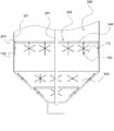
- Figure 1 is a schematic structural view of an embodiment of the present invention
- FIG. 1A is a schematic structural view of still another embodiment of the broken arch wheel of the present invention.
- FIG. 1B is a schematic structural view of a third embodiment of the broken arch of the present invention.
- FIG. 2 is a schematic structural view of another embodiment of the present invention.
- Figure 3 is a schematic structural view of still another embodiment of the present invention.
- Figure 4 is a schematic structural view of a fourth embodiment of the present invention.
- Figure 5 is a schematic view of another embodiment of the broken arch wheel set of the present invention.
- Figure 1 is a schematic view showing the structure of a first embodiment of the present invention.
- the wheeled arching mechanism of the present invention includes at least one rotating arching wheel 100.
- the rotating arching wheel 100 is radially provided with a dialing structure 110; the rotating arching wheel 100 Rotatingly supported on the silo wall 300, at least one of the toggle structure 110 of the rotating arching wheel 100 is in an interference state with the moving member 200 in the silo, and the moving component 200 is moved during the movement of the rotating arching wheel 100.
- the surrounding dial structure 110 causes it to rotate and break the material close to the wall surface 300 of the silo.
- the working principle of the present invention is that the broken arch 100 is rotatably supported along the wall surface 300 of the silo.
- the toggle structure 110 of the broken arch 100 in an interference state is toggled to break
- the arching wheel 100 then rotates to disturb the material on the wall 300 of the silo, thereby achieving the arching of the movement of the silo wall 300.
- the rotating broken arch wheel 100 is a roulette type arching wheel 120, and includes a wheel disc 120.
- the periphery of the wheel disc 121 radially protrudes from the extending lever 122 to form a rotation.
- the toggle structure 110 of the broken arch wheel 100 is a roulette type arching wheel 120, and includes a wheel disc 120.
- the rotary breaking arch 100 of the present invention is a lever type which is a combination of a coaxially disposed lever 131.
- the broken arch wheel 130, the intersecting dial 131 constitutes the toggle structure 110 of the rotary breaking arch 100.
- the moving member 200 in the silo is constituted by a discharging device 210 disposed at the bottom of the silo; the rotating broken arch 100 is disposed adjacent to the discharging device 210.
- the hopper cone surface 310 of the silo is mounted with the dialing structure 110 (120) in an interference state with the discharge device 210.
- the discharging device 210 is a discharging auger 220, and the sliding structure 110 of the rotating broken arch wheel 100 is interfered with the maximum diameter of the discharging auger 220, and the auger 220 is discharged.
- the spiral blade 221 is turned to break the arch 100 to rotate the arch.
- the breaking arch 100 is disposed in parallel along the discharge device 210, and the discharge device 210 constituted by the discharge auger 220 or the discharge conveyor 230 constitutes the moving member 200 of the present invention.
- the discharge device 210 is started to discharge, the broken arch 100 disposed in interference with the discharge device 210 is moved to rotate against the wall surface 300 of the silo.
- the movement of the broken arch wheel 100 itself does not need to be separately provided with a driving device, that is, the structure of the arching device is simplified, and the arching and discharging are conveniently performed simultaneously.
- the discharge device 210 is a discharge conveyor belt 230.
- the conveyor belt 230 is spaced apart from the top of the conveyor belt 230 with a paddle 231 or a lever 232.
- the rotary breaking arch wheel 100 The toggle structure 110 is mounted in interference with the paddles 231 or the levers 232 of the conveyor belt 230.
- the paddles 231 or the levers 232 of the conveyor belt 230 sway the arching wheel 100 to rotate the arch.
- the interference arrangement constitutes a manner in which the broken arch wheel sets 101 are linearly arranged.
- the broken arch 100 of the lower layer adjacent to the discharge conveyor 230 is interposed with the conveyor belt 230 (or the discharge auger 220) constituting the discharge device 210 to constitute the driving wheel 102 of the broken arch group 101.
- the discharge device 210 moves the drive wheel 102 of the broken arch wheel set 101 to rotate the arch.
- the driving wheel 102 toggles the upper arching wheel 100 with its interference setting to simultaneously rotate the arch.
- Still another embodiment of the present invention as shown in FIG. 3 is an embodiment of the present invention applied to the silo 320.
- the moving member 200 in the silo is formed by a rotating arching device 240 disposed in the silo 320.
- the rotating arching device 240 is provided with a breaking arm 242; the arching arm 242 is disposed on the silo wall 300
- the toggle structure 110 of the rotating broken arch wheel 100 is mounted in an interference state, and the broken arch arm 242 sways the broken arch wheel 100 to rotate the arch.
- the embodiment can realize the breaking of the wall of the tubular silo, and can be set for the material of the silo, corresponding to the rotary arching device 240 on the cylindrical silo wall, and the arcuate silo hopper 322 area is set.
- the multi-layer broken arch wheel 100 realizes the arching of the side wall of the silo wall 320.
- the drive wheels 250 constituting the moving member 200 of the present invention can be disposed at any position of the silo wall surface 300 without being restricted by the position. And by means of the interference design between the broken arches 100, the broken arch wheel set 101 can be arranged at any easy arching position of the silo wall 300.
- Figure 5 is an alternative to the broken arch wheel set of the present invention.
- the broken arch wheel 100 of the broken arch wheel set 101 can be rotatably supported on a connecting plate 102 to form a broken arch wheel set 101.
- any area connected to the wall surface 300 of the silo is fixedly connected by the connecting plate 102, that is, the broken arch group 101 is formed in this area.
Landscapes
- Engineering & Computer Science (AREA)
- Mechanical Engineering (AREA)
- Filling Or Emptying Of Bunkers, Hoppers, And Tanks (AREA)
- Mixers Of The Rotary Stirring Type (AREA)
Abstract
一种轮式破拱机构,至少包括有一个转动式破拱轮(100),转动式破拱轮(100)周边放射地设置有拨动结构(110);所述转动式破拱轮(100)转动支撑于料仓壁面,至少有一个转动式破拱轮(100)的拨动结构(110)与料仓内运动部件(200)呈干涉状态,所述运动部件(200)运动过程中拨动转动式破拱轮(100)的周边的拨动结构(110)使其随转动,对贴近料仓壁面的物料进行破拱。所述轮式破拱机构改善物料在料仓壁面上的流动性,避免料仓壁面上的结拱。
Description
本发明是关于一种用于存储松散状物料的料仓破拱机构。具体地讲是一种可实现料仓壁面运动破拱的轮式破拱机构。
在综上所述的料仓的共同特点是料仓的底部均设有锥形的仓斗结构,该锥形仓斗因其锥面会对物料提供一个垂直方向和支撑分力,因此,仓斗锥面上的物料的流动性很差,也非常容易堆积并形成结拱。通过对这种料仓物料的流动性的分析结果可以看出,在出料时在料仓的锥形仓斗及其与仓斗连接处是物料的流动性最差的D区,因此也是最容易结拱的区域。
另外,由于上述常用的料仓的仓斗结构以及位于仓斗底部的出料口远远小于其上部的料仓体的截面积。因此当物料自然下落至收缩状锥形仓斗位置时,物料因压力增大而被挤压拥堵,并因此而形成结拱。特别是在相对于比较大的料仓,或者存储纤维状物料的料仓而言,上述常规料仓完全自然状态的卸料几乎是不可能的。因此各种破拱装置成为料仓中必不可少的装置。
从运动式、振动式和气动式三种常用的破拱装置的应用范围来看,运动式破拱主要应用于存储如粮食、生物质松散状原料等颗粒或纤维粒状物料的料仓。通常情况下,运动破拱装置设置于料仓内,由驱动装置带动其在料仓内转动或移动,对其周边的物料进行扰动破拱,使得物料能流动起来,实现顺利出料。但是,现有的安装置于料仓内的运动式破拱装置,因其结构以及运动范围的限制,在运动状态下的破拱元件很难触及到料仓内物料流动性最差且最容易结拱的D区,因此物料沿在D区的仓壁结构的现象非常严重。特别是在料仓的锥形仓差距的锥面上的物料结拱,直接影响到物料的顺利出料。因此现有的运动破拱方式很难实现料仓壁面的破拱。最传统的壁面破拱通常是由人力从仓外锤击,这种壁面破拱只能适用于小
型料仓,人力所能触及的位置。大型料仓的壁面破拱通常采用振动破拱的方式,但是相对于一些纤维状的物料而言,这种振动破拱方式会往往使得物料相互间更为致密而加剧结拱。
另外,现有的运动式破拱装置中的运动部件通常是由专门的动力装置驱动,该动力装置通常设置于料仓内,不得不在仓内极端恶劣的环境下运行。运动破拱装置的运动方式比较复杂,其运动结构的设计也比较复杂。
发明内容
本发明的目的是提供一种可实现料仓壁面破拱的破拱装置,改善物料在料仓壁面上的流动性,避免料仓壁面结构上的结拱。
本发明的另一目的在于提供一种安装容易,利用料仓原动力系统实现料仓料壁破拱的功能。
上述本发明的目的,是由以下的技术方案所实现:
一种轮式破拱机构,至少包括有一个转动式破拱轮,转动式破拱轮周边放射地设置有拨动结构;所述转动式破拱轮转动支撑于料仓壁面,至少有一个转动式破拱轮的拨动结构与料仓内运动部件呈干涉状态,所述运动部件运动过程中拨动转动式破拱轮的周边的拨动结构使其随转动,对贴近料仓壁面的物料进行破拱。
本发明的可选择实施方案包括:
所述的转动式破拱轮为轮盘式破拱轮,包括轮盘以及其周边径向放射地伸出有拨杆或拨片构成转动式破拱轮的拨动结构;或为成同轴交叉设置的拨杆组合而成,构成转动式破拱轮的拨动结构;或为轮齿式破拱轮,其轮盘周边设有的轮齿,构成转动式破拱轮的拨动结构。
所述的转动式破拱轮相互间可间隔设置,分别与所述运动部件呈干涉状态安装。或由多个转动式破拱轮相互间可干涉状态安装,组成转动式破拱轮组;其中一个转动式破拱轮与所述运动部件呈干涉状态,构成该组破拱轮的主动轮。所述的由相互干涉的破拱轮组合而成的破拱轮组可呈线性或非线性排列。
所述的料仓内运动部件为设置于料仓侧底部的出料装置;所述转动式破拱轮设置于邻近于出料装置的料仓锥形仓斗的侧壁上,其拨动结构与出料装置呈干涉状态安装。其中,所述出料装置为绞龙,转动式破拱轮的拨动结构与绞龙最大直径干涉安装,出料绞龙转动出料时,其螺旋叶片拨动破拱轮转动破拱;或所述出料装置为传送带,该传送带间隔设置有拨片或拨杆,转动式破拱轮的拨动结构与传送带的拨片或拨杆干涉安装,传送带移动时,传送带的拨片或拨杆拨动破拱轮转动破拱。
在本发明一可选实施例,所述的料仓内运动部件为设置于料仓内的转动式破拱装置构成,所述转动式破拱装置设有破拱臂;该破拱臂与设置于料仓壁上的转动式破拱轮的拨动结构呈干涉状态安装,该破拱臂拨动破拱轮转动破拱。所述的转动式破拱装置可垂直设置于料仓内,该垂直式的转动式破拱装置可设有多层水平转动破拱臂;每层转动破拱臂对应于料仓侧臂上排列的破拱轮的高度,悬臂端与破拱轮干涉。
本发明一可选实施例,所述的料仓内运动部件由动力驱动的驱动轮构成,该驱动轮周边设有拨动结构与破拱轮干涉设置,驱动轮受控转动时,带动破拱轮转动破拱。所述的驱动轮的驱动装置可设置于仓外。
在本发明中,所述的破拱轮组中的破拱轮可分别转动支撑于一连接板上,通过该连接板固定连接于料仓壁。
本发明的工作原理及其效果是显著的。
本发明的工作原理是,在料仓壁面上转动地设有破拱轮,破拱轮周边设有拨动装置,该拨动装置与运动部件干涉设置,当运动部件运动过程中,拨动破拱轮转动,对贴近料仓壁面上的物料进行扰动,从而实现对料仓壁的运动破拱。
本发明中的破拱轮可以方便地安装置于料仓壁面的任何位置,特别是料仓内其它破拱装置很难触及到、且物料流动性最差且最容易结拱的位于料仓仓斗区域的壁面上。本发明中的破拱轮自身并不设有驱动元件,其运动状态可以由破拱轮与料仓内的常用的运动元件的干涉结构实现,例如输出绞龙、运动破拱机构的转动部件或简单的驱动轮等。因此,本发明的结构简单,安装容易的特点。
本发明中的破拱轮间可以相互呈干涉设置,其彼此可以相互驱动而转动破拱,形成沿壁面设置的破拱群,可以依料仓内的结构状态设置于料仓的任意易结拱区域的邻近壁面上。
为令本发明的目的、技术手段及技术效果有更完整及清楚的揭露,以下进行详细说明,并请一并参阅附图及部件标号。
图1 本发明的一种实施方式的结构示意图;
图1A 本发明破拱轮的再一种实施例的结构示意图;
图1B 本发明破拱轮的第三种实施例的结构示意图;
图2 本发明另一种实施方式的结构示意图;
图3 本发明再一种实施方式的结构示意图;
图4 本发明第四种实施方式的结构示意;
图5 本发明破拱轮组的另一种实施方式示意图。
图号说明:
100-破拱轮;110-拨动结构。101-破拱轮组;102-破拱轮组连接板。
120-轮盘式破拱轮;121-轮盘;122-拨杆。
130-拨杆式破拱轮;131-伸出拨杆。140-轮齿式破拱轮;141-轮齿。
200-运动部件。220-出料绞龙;221-螺旋叶片。
230-出料传送带;231-拨片;232-拨杆;
240-转动式破拱装置;241-转动轴;242-破拱臂;243-悬臂端。
250-驱动轮;251-拨动结构。
300-料仓壁面;310-仓斗锥面。320-筒仓;321-筒仓壁面;322-筒仓仓斗。
结合附图和本发明具体实施方式的描述,能够更加清楚地了解本发明的细节。但是,在此描述的本发明的具体实施方式,仅用于解释本发明的目的,而不能以任何方式理解成是对本发明的限制。在本发明的教导下,技术人员可以构想基于本发明的任意可能的变形,这些都应被视为属于本发明的范围。
图1为本发明的第一种实施方式的结构示意图。
如图1所示,本发明的轮式破拱机构,至少包括有一个转动式破拱轮100,转动式破拱轮100周边放射地设置有拨动结构110;所述转动式破拱轮100转动支撑于料仓壁面300,至少有一个转动式破拱轮100的拨动结构110与料仓内运动部件200呈干涉状态,所述运动部件200运动过程中拨动转动式破拱轮100的周边的拨动结构110使其随转动,对贴近料仓壁面300的物料进行扰动破拱。
本发明的工作原理是,破拱轮100沿料仓壁面300转动支撑设置,当运动部件200启动时而呈运动状态时,拨动与其呈干涉状态的破拱轮100的拨动结构110,使得破拱轮100随之转动,对贴近料仓壁面300上的物料实施扰动,从而实现对料仓壁面300的运动破拱。
本实施例中,所述的转动式破拱轮100为轮盘式破拱轮120,包括有轮盘120,所述轮盘121的周边径向放射地伸出有伸出拨杆122构成转动式破拱轮100的拨动结构110。
如图1A所示,本发明的转动式破拱轮100为同轴交叉设置的拨杆131组合而成的拨杆式
破拱轮130,所述的交叉设置的拨杆131构成转动式破拱轮100的拨动结构110。
如图1B所示,本发明的转动式破拱轮为轮齿式破拱轮140,所述轮齿式破拱轮140周边设有轮齿141,构成转动式破拱轮100的拨动结构110。
在本实施例中,所述的转动式破拱轮100相互间可间隔设置,分别与所述运动部件200呈干涉状态安装。
在如图1所示出的实施方式中,所述的料仓内运动部件200由设置于料仓底部的出料装置210构成;所述转动式破拱轮100设置于邻近于出料装置210的料仓的仓斗锥面310上,其拨动结构110(120)与出料装置210呈干涉状态安装。
具体在本实施例中,所述的所述出料装置210为出料绞龙220,转动式破拱轮100的拨动结构110与出料绞龙220最大直径干涉安装,出料绞龙220转动出料时,其螺旋叶片221拨动破拱轮100转动破拱。
在上述实施方式中,破拱轮100沿出料装置210平行设置,由出料绞龙220或出料传送带230构成的出料装置210构成本发明的运动部件200。启动出料装置210出料时,与出料装置210干涉设置的破拱轮100被拨动而贴近料仓壁面300转动。本实施方式中,所述的破拱轮100本身的运动无需单独设置驱动装置,即简化破拱装置的结构,又能方便地实现破拱与出料同步进行。
在图2所示出的本发明的另一种实施方式中,所述出料装置210为出料传送带230,该传送带230上方间隔设置有拨片231或拨杆232,转动式破拱轮100的拨动结构110与传送带230的拨片231或拨杆232干涉安装。传送带230移动时,传送带230的拨片231或拨杆232拨动破拱轮100转动破拱。
在图2所示的实施方式中,由两个或两个以上的转动式破拱轮100相互间干涉状态安装,组成转动式破拱轮组101;其中一个转动式破拱轮100与所述运动部件200呈干涉状态,构成该组破拱轮101的主动轮102。
例如,如图2所示,在锥形的仓斗锥面310上至少平行设置有两排破拱轮100,其中上层的破拱轮100与下层破拱轮邻100的拨动结构110之间干涉设置,构成破拱轮组101呈线性排列的方式。其中下层邻近出料传送带230的破拱轮100与构成出料装置210的传送带230(或出料绞龙220)干涉设置,构成破拱轮组101的主动轮102。启动出料装置210出料时,出料装置210拨动破拱轮组101的主动轮102转动破拱。同时,主动轮102拨动与其干涉设置的上层破拱轮100同时转动破拱。
如图3所示的本发明的再一实施方式,是本发明应用于筒仓320的一种本实施方式。所述
料仓内运动部件200为设置于筒仓320内的转动式破拱装置240构成,所述转动式破拱装置240设有破拱臂242;该破拱臂242与设置于料仓壁面300上的转动式破拱轮100的拨动结构110呈干涉状态安装,该破拱臂242拨动破拱轮100转动破拱。
具体在本实施方式中,破拱轮100沿料筒仓壁面321设置,所述的转动式破拱装置240可垂直设置于料仓内,该垂直式的转动式破拱装置240可设有多层水平转动破拱臂242;每层转动破拱臂242对应于筒仓壁321上排列的破拱轮100的高度,破拱臂242的悬臂端243与破拱轮的拨动结构110干涉设置。当转动式破拱装置240转动破拱时,破拱臂242随转轴241转动,同时拨动与破拱臂242干涉设置的破拱轮100转动破拱。本实施方式可以在对料仓内物料破拱的同时实现对筒仓壁320上的物料进行破拱。
本实施方式可以实现筒形料仓的仓壁破拱,可以针对料仓存储的物料特性,对应于转动式破拱装置240在筒形仓壁上,易结拱的筒仓仓斗322区域设置多层破拱轮100,实现筒仓壁320的侧壁破拱。
如图4所示的本发明的可选实施方式中,在料仓壁面300的易结拱处排列多个破拱轮100,该些破拱轮100非线性排列,构成有一组或数组破拱轮群101。所述的料仓内运动部件200由动力驱动的驱动轮250构成,该驱动轮250周边设有拨动结构251,并与破拱轮100干涉设置,驱动轮250受控转动时,带动破拱轮100转动破拱。所述的驱动轮250的驱动动力装置252可设置于仓外。该驱动轮250的驱动动力装置252可单独受控开启或关闭。
本实施方式中,构成本发明运动部件200的驱动轮250可以不受位置的限制设置于料仓壁面300的任意位置。并且通过破拱轮100间的干涉设计,可以在料仓壁面300的任意易结拱位置设置破拱轮组101。
图5是本发明破拱轮组的一种可选方案。如图5所示,所述的破拱轮组101中的破拱轮100可分别转动支撑于一连接板102上,构成一个破拱轮组101。再通过连接板102固定连接于料仓壁面300上的任意区域,即在该区域构成破拱轮组101。
以上所举仅为本发明示意性的部分实施例,并非用以限制本发明的范围,任何本领域的技术人员,在不脱离本发明的构思和原则的前提下所作出的等同变化与修改,均应包括在本专利保护范围之内。
Claims (15)
- 一种轮式破拱机构,其特征在于,至少包括有一个转动式破拱轮,转动式破拱轮周边放射地设置有拨动结构;所述转动式破拱轮转动支撑于料仓壁面,至少有一个转动式破拱轮的拨动结构与料仓内运动部件呈干涉状态,所述运动部件运动过程中拨动转动式破拱轮的周边的拨动结构使其随转动,对贴近料仓壁面的物料进行破拱。
- 依据权利要求1所述的轮式破拱机构,其特征在于所述的转动式破拱轮为轮盘式破拱轮,包括轮盘以及其周边径向放射地伸出有拨杆或拨片构成转动式破拱轮的拨动结构。
- 依据权利要求1所述的轮式破拱机构,其特征在于所述的转动式破拱轮为成同轴交叉设置的拨杆组合而成,构成转动式破拱轮的拨动结构。
- 依据权利要求1所述的轮式破拱机构,其特征在于所述的转动式破拱轮为轮齿式破拱轮,其周边设有轮齿构成转动式破拱轮的拨动结构。
- 依据权利要求1-4任一权利要求所述的轮式破拱机构,其特征在于所述的转动式破拱轮相互间可间隔设置,分别与所述运动部件呈干涉状态安装。
- 依据权利要求1-4任一权利要求所述的轮式破拱机构,其特征在于,由多个转动式破拱轮相互间可干涉状态安装,组成转动式破拱轮组;其中一个转动式破拱轮与所述运动部件呈干涉状态,构成该组破拱轮的主动轮。
- 依据权利要求6所述的轮式破拱机构,其特征在于,所述的由相互干涉的破拱轮组合而成的破拱轮组可呈线性或非线性排列。
- 依据权利要求1所述的轮式破拱机构,其特征在于所述的料仓内运动部件为设置于料仓侧底部的出料装置;所述转动式破拱轮设置于邻近于出料装置的料仓锥形仓斗的侧壁上,其拨动结构与出料装置呈干涉状态安装。
- 依据权利要求8所述的轮式破拱机构,其特征在于所述出料装置为绞龙,转动式破拱轮的拨动结构与绞龙最大直径干涉安装,出料绞龙转动出料时,其螺旋叶片拨动破拱轮转动破拱。
- 依据权利要求8所述的轮式破拱机构,其特征在于所述出料装置为传送带,该传送带间隔设置有拨片或拨杆,转动式破拱轮的拨动结构与传送带的拨片或拨杆干涉安装,传送带移动时,传送带的拨片或拨杆拨动破拱轮转动破拱。
- 依据权利要求1所述的轮式破拱机构,其特征在于所述的料仓内运动部件为设置于料仓内的转动式破拱装置构成,所述转动式破拱装置设有破拱臂;该破拱臂与设置于料仓壁上的转动式破拱轮的拨动结构呈干涉状态安装,该破拱臂拨动破拱轮转动破拱。
- 依据权利要求11所述的轮式破拱机构,其特征在于所述的转动式破拱装置可垂直设置于料仓内,该垂直式的转动式破拱装置可设有多层水平转动破拱臂;每层转动破拱臂对应于料仓侧臂上排列的破拱轮的高度,悬臂端与破拱轮干涉。
- 依据权利要求1所述的轮式破拱机构,其特征在于所述的料仓内运动部件由动力驱动的驱动轮构成,该驱动轮周边设有拨动结构与破拱轮干涉设置,驱动轮受控转动时,带动破拱轮转动破拱。
- 依据权利要求13所述的轮式破拱机构,其特征在于所述的驱动轮的驱动装置可设置于仓外。
- 依据权利要求6所述的轮式破拱机构,其特征在于所述的破拱轮组中的破拱轮可分别转动支撑于一连接板上,通过该连接板固定连接于料仓壁。
Applications Claiming Priority (2)
| Application Number | Priority Date | Filing Date | Title |
|---|---|---|---|
| CN201410046650.X | 2014-01-30 | ||
| CN201410046650.XA CN104816895A (zh) | 2014-01-30 | 2014-01-30 | 一种轮式破拱机构 |
Publications (1)
| Publication Number | Publication Date |
|---|---|
| WO2015113517A1 true WO2015113517A1 (zh) | 2015-08-06 |
Family
ID=53727418
Family Applications (1)
| Application Number | Title | Priority Date | Filing Date |
|---|---|---|---|
| PCT/CN2015/071925 Ceased WO2015113517A1 (zh) | 2014-01-30 | 2015-01-30 | 一种轮式破拱机构 |
Country Status (2)
| Country | Link |
|---|---|
| CN (1) | CN104816895A (zh) |
| WO (1) | WO2015113517A1 (zh) |
Cited By (14)
| Publication number | Priority date | Publication date | Assignee | Title |
|---|---|---|---|---|
| EP3081069A1 (de) * | 2015-04-14 | 2016-10-19 | Deere & Company | Fördereinrichtung zur vermeidung von brückenbildung beim entladen von erntegut aus einem korntank eines mähdreschers |
| CN107215579A (zh) * | 2017-07-14 | 2017-09-29 | 洛阳蓝斯利科技有限公司 | 一种适用于粉碎甘草存放的料仓 |
| CN107597273A (zh) * | 2017-10-17 | 2018-01-19 | 江苏秋林特能装备股份有限公司 | 双齿辊给料仓 |
| CN109051382A (zh) * | 2018-09-30 | 2018-12-21 | 郑州运达造纸设备有限公司 | 一种秸秆类制浆原料输送机 |
| CN109875080A (zh) * | 2019-04-02 | 2019-06-14 | 上海天一高德机电实业有限公司 | 一种经过高温灭菌熟化饲料的生产装置及工艺 |
| CN110203719A (zh) * | 2019-06-22 | 2019-09-06 | 李克明 | 料仓 |
| CN110510269A (zh) * | 2019-10-16 | 2019-11-29 | 江苏华泰重工装备有限公司 | 一种料仓破桥装置 |
| CN111345148A (zh) * | 2020-04-27 | 2020-06-30 | 岭南生态文旅股份有限公司 | 一种间歇式下料的施肥设备 |
| CN111824609A (zh) * | 2020-05-06 | 2020-10-27 | 河南众森电力设备有限公司 | 一种固体物料仓防堵装置 |
| CN113682665A (zh) * | 2021-08-26 | 2021-11-23 | 建龙阿城钢铁有限公司 | 一种辅助卸灰旋转破料装置 |
| CN114572714A (zh) * | 2022-03-17 | 2022-06-03 | 濮阳市伍钰泉面业集团有限公司 | 一种振动仓底卸料器 |
| CN115088632A (zh) * | 2022-06-24 | 2022-09-23 | 山东省农业机械科学研究院 | 一种破结拱精准分流智能饲喂器及使用方法 |
| CN116161345A (zh) * | 2023-04-14 | 2023-05-26 | 湖南润天智科机械制造有限公司 | 一种沥青站冷料仓破拱装置 |
| CN116639396A (zh) * | 2023-07-12 | 2023-08-25 | 河南沧净环保科技有限公司 | 一种用于料仓机械破拱输送的计量投加装置 |
Families Citing this family (1)
| Publication number | Priority date | Publication date | Assignee | Title |
|---|---|---|---|---|
| CN105501713A (zh) * | 2016-01-14 | 2016-04-20 | 江苏搏斯威化工设备工程有限公司 | 一种粘性物料的搅拌输送系统 |
Citations (4)
| Publication number | Priority date | Publication date | Assignee | Title |
|---|---|---|---|---|
| US1960778A (en) * | 1931-08-07 | 1934-05-29 | John C Goss | Fuel agitator |
| US4056215A (en) * | 1976-04-26 | 1977-11-01 | Elex A.G. | Anti-bridging device |
| US20030234261A1 (en) * | 2002-06-25 | 2003-12-25 | Gerhard Ufheil | Dispensing canister |
| CN201961725U (zh) * | 2010-12-22 | 2011-09-07 | 于红燕 | 料仓破拱装置 |
-
2014
- 2014-01-30 CN CN201410046650.XA patent/CN104816895A/zh active Pending
-
2015
- 2015-01-30 WO PCT/CN2015/071925 patent/WO2015113517A1/zh not_active Ceased
Patent Citations (4)
| Publication number | Priority date | Publication date | Assignee | Title |
|---|---|---|---|---|
| US1960778A (en) * | 1931-08-07 | 1934-05-29 | John C Goss | Fuel agitator |
| US4056215A (en) * | 1976-04-26 | 1977-11-01 | Elex A.G. | Anti-bridging device |
| US20030234261A1 (en) * | 2002-06-25 | 2003-12-25 | Gerhard Ufheil | Dispensing canister |
| CN201961725U (zh) * | 2010-12-22 | 2011-09-07 | 于红燕 | 料仓破拱装置 |
Cited By (17)
| Publication number | Priority date | Publication date | Assignee | Title |
|---|---|---|---|---|
| EP3081069A1 (de) * | 2015-04-14 | 2016-10-19 | Deere & Company | Fördereinrichtung zur vermeidung von brückenbildung beim entladen von erntegut aus einem korntank eines mähdreschers |
| CN107215579A (zh) * | 2017-07-14 | 2017-09-29 | 洛阳蓝斯利科技有限公司 | 一种适用于粉碎甘草存放的料仓 |
| CN107597273A (zh) * | 2017-10-17 | 2018-01-19 | 江苏秋林特能装备股份有限公司 | 双齿辊给料仓 |
| CN109051382A (zh) * | 2018-09-30 | 2018-12-21 | 郑州运达造纸设备有限公司 | 一种秸秆类制浆原料输送机 |
| CN109875080B (zh) * | 2019-04-02 | 2024-03-08 | 上海天一高德机电实业有限公司 | 一种经过高温灭菌熟化饲料的生产装置及工艺 |
| CN109875080A (zh) * | 2019-04-02 | 2019-06-14 | 上海天一高德机电实业有限公司 | 一种经过高温灭菌熟化饲料的生产装置及工艺 |
| CN110203719A (zh) * | 2019-06-22 | 2019-09-06 | 李克明 | 料仓 |
| CN110510269A (zh) * | 2019-10-16 | 2019-11-29 | 江苏华泰重工装备有限公司 | 一种料仓破桥装置 |
| CN111345148A (zh) * | 2020-04-27 | 2020-06-30 | 岭南生态文旅股份有限公司 | 一种间歇式下料的施肥设备 |
| CN111824609A (zh) * | 2020-05-06 | 2020-10-27 | 河南众森电力设备有限公司 | 一种固体物料仓防堵装置 |
| CN113682665A (zh) * | 2021-08-26 | 2021-11-23 | 建龙阿城钢铁有限公司 | 一种辅助卸灰旋转破料装置 |
| CN114572714A (zh) * | 2022-03-17 | 2022-06-03 | 濮阳市伍钰泉面业集团有限公司 | 一种振动仓底卸料器 |
| CN114572714B (zh) * | 2022-03-17 | 2024-04-09 | 濮阳市伍钰泉面业集团有限公司 | 一种振动仓底卸料器 |
| CN115088632A (zh) * | 2022-06-24 | 2022-09-23 | 山东省农业机械科学研究院 | 一种破结拱精准分流智能饲喂器及使用方法 |
| CN115088632B (zh) * | 2022-06-24 | 2023-06-09 | 山东省农业机械科学研究院 | 一种破结拱精准分流智能饲喂器及使用方法 |
| CN116161345A (zh) * | 2023-04-14 | 2023-05-26 | 湖南润天智科机械制造有限公司 | 一种沥青站冷料仓破拱装置 |
| CN116639396A (zh) * | 2023-07-12 | 2023-08-25 | 河南沧净环保科技有限公司 | 一种用于料仓机械破拱输送的计量投加装置 |
Also Published As
| Publication number | Publication date |
|---|---|
| CN104816895A (zh) | 2015-08-05 |
Similar Documents
| Publication | Publication Date | Title |
|---|---|---|
| WO2015113517A1 (zh) | 一种轮式破拱机构 | |
| CN203020821U (zh) | 一种破拱料斗 | |
| CN103129862B (zh) | 一种能防止堵料的生物质原料仓 | |
| CN207618533U (zh) | 一种落料传送装置 | |
| RU2550239C1 (ru) | Устройство для выгрузки кускового материала из бункера | |
| WO2015113514A1 (zh) | 一种破拱单元及料仓 | |
| CN102556539B (zh) | 带有中心出料斗的振动卸料筒仓及卸料方法 | |
| CN204310274U (zh) | 料仓出料防堵装置 | |
| CN204660889U (zh) | 一种给料装置 | |
| CN103407704A (zh) | 可多点出料的料仓出料装置 | |
| CN102756872A (zh) | 一种煤仓自动清堵机 | |
| CN212173881U (zh) | 一种库底下料装置 | |
| CN205312285U (zh) | 一种带有旋转式内锥体结构的中心给料机 | |
| CN203222261U (zh) | 钢板筒仓螺旋破拱装置 | |
| CN207861016U (zh) | 一种防堵塞型粉末料仓 | |
| CN105377725A (zh) | 破拱装置及具有该破拱装置的分料调峰池 | |
| CN202974696U (zh) | 一种缩分装置 | |
| CN202358672U (zh) | 新型物料给料装置 | |
| CN206720008U (zh) | 湿矿卸料斗 | |
| CN204254657U (zh) | 木片料仓平衡供料装置 | |
| CN203938045U (zh) | 抖料装置、料斗及猪用选种选料机 | |
| CN205708200U (zh) | 玻璃混合料振动下料仓 | |
| CN203364572U (zh) | 转筒干燥机中心出料装置 | |
| CN210259640U (zh) | 一种烟气脱硫用不易板结的石灰石粉仓 | |
| CN203079056U (zh) | 物料仓周向防堵装置 |
Legal Events
| Date | Code | Title | Description |
|---|---|---|---|
| 121 | Ep: the epo has been informed by wipo that ep was designated in this application |
Ref document number: 15742834 Country of ref document: EP Kind code of ref document: A1 |
|
| NENP | Non-entry into the national phase |
Ref country code: DE |
|
| 122 | Ep: pct application non-entry in european phase |
Ref document number: 15742834 Country of ref document: EP Kind code of ref document: A1 |