WO2015114730A1 - ターニング装置及び回転機械 - Google Patents
ターニング装置及び回転機械 Download PDFInfo
- Publication number
- WO2015114730A1 WO2015114730A1 PCT/JP2014/051756 JP2014051756W WO2015114730A1 WO 2015114730 A1 WO2015114730 A1 WO 2015114730A1 JP 2014051756 W JP2014051756 W JP 2014051756W WO 2015114730 A1 WO2015114730 A1 WO 2015114730A1
- Authority
- WO
- WIPO (PCT)
- Prior art keywords
- wheel
- gear
- casing
- drive
- lever
- Prior art date
- Legal status (The legal status is an assumption and is not a legal conclusion. Google has not performed a legal analysis and makes no representation as to the accuracy of the status listed.)
- Ceased
Links
Images
Classifications
-
- F—MECHANICAL ENGINEERING; LIGHTING; HEATING; WEAPONS; BLASTING
- F01—MACHINES OR ENGINES IN GENERAL; ENGINE PLANTS IN GENERAL; STEAM ENGINES
- F01D—NON-POSITIVE DISPLACEMENT MACHINES OR ENGINES, e.g. STEAM TURBINES
- F01D25/00—Component parts, details, or accessories, not provided for in, or of interest apart from, other groups
- F01D25/34—Turning or inching gear
-
- F—MECHANICAL ENGINEERING; LIGHTING; HEATING; WEAPONS; BLASTING
- F01—MACHINES OR ENGINES IN GENERAL; ENGINE PLANTS IN GENERAL; STEAM ENGINES
- F01D—NON-POSITIVE DISPLACEMENT MACHINES OR ENGINES, e.g. STEAM TURBINES
- F01D15/00—Adaptations of machines or engines for special use; Combinations of engines with devices driven thereby
- F01D15/08—Adaptations for driving, or combinations with, pumps
-
- F—MECHANICAL ENGINEERING; LIGHTING; HEATING; WEAPONS; BLASTING
- F01—MACHINES OR ENGINES IN GENERAL; ENGINE PLANTS IN GENERAL; STEAM ENGINES
- F01D—NON-POSITIVE DISPLACEMENT MACHINES OR ENGINES, e.g. STEAM TURBINES
- F01D21/00—Shutting-down of machines or engines, e.g. in emergency; Regulating, controlling, or safety means not otherwise provided for
-
- F—MECHANICAL ENGINEERING; LIGHTING; HEATING; WEAPONS; BLASTING
- F16—ENGINEERING ELEMENTS AND UNITS; GENERAL MEASURES FOR PRODUCING AND MAINTAINING EFFECTIVE FUNCTIONING OF MACHINES OR INSTALLATIONS; THERMAL INSULATION IN GENERAL
- F16H—GEARING
- F16H1/00—Toothed gearings for conveying rotary motion
- F16H1/02—Toothed gearings for conveying rotary motion without gears having orbital motion
- F16H1/20—Toothed gearings for conveying rotary motion without gears having orbital motion involving more than two intermeshing members
-
- F—MECHANICAL ENGINEERING; LIGHTING; HEATING; WEAPONS; BLASTING
- F16—ENGINEERING ELEMENTS AND UNITS; GENERAL MEASURES FOR PRODUCING AND MAINTAINING EFFECTIVE FUNCTIONING OF MACHINES OR INSTALLATIONS; THERMAL INSULATION IN GENERAL
- F16H—GEARING
- F16H35/00—Gearings or mechanisms with other special functional features
- F16H35/18—Turning devices for rotatable members, e.g. shafts
-
- F—MECHANICAL ENGINEERING; LIGHTING; HEATING; WEAPONS; BLASTING
- F16—ENGINEERING ELEMENTS AND UNITS; GENERAL MEASURES FOR PRODUCING AND MAINTAINING EFFECTIVE FUNCTIONING OF MACHINES OR INSTALLATIONS; THERMAL INSULATION IN GENERAL
- F16H—GEARING
- F16H59/00—Control inputs to control units of change-speed- or reversing-gearings for conveying rotary motion
- F16H59/02—Selector apparatus
-
- F—MECHANICAL ENGINEERING; LIGHTING; HEATING; WEAPONS; BLASTING
- F05—INDEXING SCHEMES RELATING TO ENGINES OR PUMPS IN VARIOUS SUBCLASSES OF CLASSES F01-F04
- F05D—INDEXING SCHEME FOR ASPECTS RELATING TO NON-POSITIVE-DISPLACEMENT MACHINES OR ENGINES, GAS-TURBINES OR JET-PROPULSION PLANTS
- F05D2220/00—Application
- F05D2220/30—Application in turbines
- F05D2220/31—Application in turbines in steam turbines
-
- F—MECHANICAL ENGINEERING; LIGHTING; HEATING; WEAPONS; BLASTING
- F16—ENGINEERING ELEMENTS AND UNITS; GENERAL MEASURES FOR PRODUCING AND MAINTAINING EFFECTIVE FUNCTIONING OF MACHINES OR INSTALLATIONS; THERMAL INSULATION IN GENERAL
- F16H—GEARING
- F16H3/00—Toothed gearings for conveying rotary motion with variable gear ratio or for reversing rotary motion
- F16H3/02—Toothed gearings for conveying rotary motion with variable gear ratio or for reversing rotary motion without gears having orbital motion
- F16H3/20—Toothed gearings for conveying rotary motion with variable gear ratio or for reversing rotary motion without gears having orbital motion exclusively or essentially using gears that can be moved out of gear
- F16H3/34—Toothed gearings for conveying rotary motion with variable gear ratio or for reversing rotary motion without gears having orbital motion exclusively or essentially using gears that can be moved out of gear with gears shiftable otherwise than only axially
Definitions
- the present invention relates to a turning device that rotates a rotor such as a turbine at a low speed, and a rotating machine including the turning device.
- the turning apparatus described in Patent Document 1 includes a drive motor.
- the shaft of the drive motor is connected to a speed reduction mechanism that reduces the rotation of the shaft.
- the reduction mechanism includes a drive pulley (drive wheel), and the rotation of the reduced drive motor is transmitted to the drive pulley.
- a driven pulley (driven wheel) having the same axial direction as that of the drive pulley is disposed below the speed reduction mechanism.
- a V-belt annular member
- a first spur gear that rotates about the same axis is integrally attached to the drive pulley.
- a second spur gear having the same axial direction as that of the first spur gear is disposed below the first spur gear. The first spur gear and the second spur gear are always meshed.
- a pair of arm members are supported on the rotation shaft of the second spur gear so as to be tiltable so as to sandwich the second spur gear from the axial direction.
- a pinion gear (second tooth ring) having the same axial direction as that of the second spur gear and the wheel gear is rotatably supported at one end of the arm member.
- the pinion gear can be displaced between a meshing position where the pinion gear approaches and meshes with the wheel gear and a retracting position spaced radially outward from the wheel gear by tilting of the arm member.
- the wheel gear is fixed coaxially to the rotor.
- one end of the rotor is connected to a compressor (compressor), and the other end of the rotor is connected to a turbine.
- the connection between the rotor and the compressor is covered with a coupling guard (shaft joint guard) to avoid oil and the like.
- the driving pulley and the driven pulley are covered with a chain cover (cover), and this chain cover is detachably attached to the compressor side portion of the turning device.
- the position of the pinion gear is set to the retracted position during the operation of the steam turbine.
- the arm member is tilted by the control unit of the turning device, and the pinion gear is displaced from the retracted position to the meshing position with the wheel gear.
- the drive motor is driven, the rotational power of the drive motor is transmitted to the wheel gear via the speed reduction mechanism, the drive / driven pulley, the V belt, the first spur gear, the second spur gear, and the pinion gear.
- a rotor rotates with a wheel gear. At this time, the rotor rotates at a lower speed than during operation of the steam turbine.
- the gear has a three-stage configuration because the coupling guard may interfere with the chain cover when the coupling guard is attached / detached. Rigidity decreases and the number of parts increases. When the coupling guard interferes with the chain cover, workability when the coupling guard is attached / detached is deteriorated.
- the present invention has been made in view of such problems, a turning device in which the number of gear stages is reduced after suppressing the coupling guard from interfering with the cover when the coupling guard is attached and detached, And it aims at providing a rotary machine provided with this turning apparatus.
- the aspect of the turning device according to the present invention includes a casing, a drive motor mounted above the casing, and above the casing, on the drive shaft of the drive motor and parallel to the vertical direction.
- a driven wheel that is rotatably supported and connected to the drive wheel via an annular member, a first tooth ring that is coaxially connected to the driven wheel and has a first spur tooth, and parallel to the reference line
- a wheel gear provided coaxially with the extending rotation shaft, a second tooth ring having a second spur tooth meshing with the first spur tooth of the first tooth ring, and the second tooth ring.
- Support for rotation A moving mechanism that moves the second tooth ring between a meshing position that meshes with the wheel gear and a retracting position that does not mesh with the wheel gear by moving the arm member and the arm member And a cover that is attachable to and detachable from the casing and covers the driving wheel, and a compressor is connected to the other side of the rotating shaft with respect to the reference surface.
- the turning device includes a rotation lever having one end connected coaxially to the drive wheel via a ratchet mechanism, and the ratchet mechanism has one end of the rotation lever with respect to the axis of the drive wheel. Restricting rotation to one side around the axis and allowing rotation to the other side around the axis, the moving mechanism having a moving lever whose one end is rotatably supported by the casing; A connecting member that is connected to each of the moving lever and the arm member, and is configured to move the arm member when the moving lever rotates, wherein the rotating lever and the moving lever are the reference More preferably, it rotates on the same side relative to the cover in the direction along the line. Moreover, the aspect of the rotating machine which concerns on this invention is provided with the turning apparatus in any one of said.
- the turning device and the rotating machine of the present invention by reducing the number of gear stages, the number of parts can be reduced, the rigidity can be increased, and the power transmission coefficient can be improved.
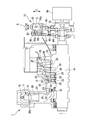
- the steam turbine 1 of the present embodiment includes an adjustment valve 11 that adjusts the amount and pressure of steam (working fluid) flowing into the steam turbine 1, a main body side casing 12 that holds the pressure, and power.
- a power generation unit 13 that generates the power
- a rotor (rotary shaft) 14 that transmits the generated power to a machine such as a compressor 69
- a bearing device (not illustrated) that rotatably supports the rotor 14 about an axis.
- the turning device 15 of the present invention for rotating the rotor 14 is provided.
- a plurality of regulating valves 11 are attached to the inside of the main body side casing 12 (only one regulating valve 11 is shown in FIG. 1), and a regulating valve chamber 18 into which steam flows from a boiler (not shown), and The valve body 19 and the valve seat 20 are provided.
- the valve seat 20 has a substantially cylindrical shape, and its axis is orthogonal to the axis of the rotor 14.
- the inner diameter of the valve seat 20 gradually increases in the direction toward the rotor 14, and the tip portion communicates with the steam chamber 21.
- the inner surface 20a of the end of the valve seat 20 opposite to the steam chamber 21 is formed in a curved surface that is convex toward the inside.
- the shape of the lower part of the valve body 19 forms a part of a sphere, and is provided so as to be able to contact and separate from the inner surface 20a of the valve seat 20.
- the regulating valve 11 controls the steam flow rate by opening and closing the valve body 19. Further, the output of the steam turbine is controlled by adjusting the opening / closing timings of the plurality of regulating valves 11.
- the steam chamber 21 guides the steam flowing from the regulating valve 11 to the power generation unit 13 and has a substantially donut shape. The steam flow path of the steam chamber 21 becomes narrower toward the inside and is deflected in a direction parallel to the axis of the rotor 14.
- the power generation unit 13 includes a nozzle 23 fixed to the main body side casing 12 and a moving blade 24 attached to the rotor 14.
- One set of the nozzle 23 and the moving blade 24 is referred to as a paragraph, and in this embodiment, the steam turbine 1 includes six paragraphs.
- the nozzle 23 expands the steam in the steam passage to generate velocity energy, and changes the flow direction to create a momentum in the rotational direction of the shaft.
- the moving blade 24 acts to convert the energy of the steam converted into velocity energy by the nozzle 23 into the rotational energy of the rotor 14.
- a large number of nozzles 23 are arranged radially and are held by a ring-shaped partition plate outer ring 25 and a ring-shaped partition plate inner ring 26 that are firmly fixed to the main body side casing 12. Between the rotor 14 side end of the inner ring 26 of the partition plate and the rotor 14 is a seal structure that prevents steam leakage. In the paragraph where the steam pressure is high, a labyrinth structure is adopted as a seal structure (not shown).
- a large number of moving blades 24 are arranged radially, and are firmly attached to the outer peripheral portion of a disk (reference numeral omitted) that protrudes from the rotor 14 and is provided in a cylindrical shape.
- a shroud 29 is attached to the tip of the rotor blade 24 at the final stage, and a fin (not shown) for preventing steam leakage is attached at a position facing the shroud 29 on the partition plate outer ring 25 side.
- the rotor 14 is formed in a rod shape and is rotatably supported by the bearing device described above.
- a wheel gear 30 is fixed to the outer peripheral surface of the rotor 14 so as to be coaxial with the rotor 14.
- the rotor 14 acts to transmit the power generated by the power generator 13 to a machine such as the compressor 69.
- a seal structure (not shown) for preventing leakage of steam or the like is provided between the rotor 14 and the main body side casing 12.
- the exhaust steam that has finished work by operating the steam turbine 1 is sent to a condenser (not shown) through an exhaust chamber 31.
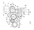
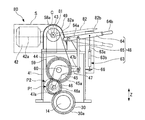
- the turning device 15 is for continuing the rotation of the rotor 14 at a much lower speed than when the steam turbine 1 is operating when the operation of the steam turbine 1 is stopped and started. 1 to 3, the turning device 15 is defined on a casing 41, a drive motor 42 attached to the casing 41, a drive shaft 42a of the drive motor 42, and a reference parallel to the vertical direction Z.
- a drive side sprocket (drive wheel) 43 rotatably supported on one side D1 with respect to the surface S, a driven side sprocket (driven wheel) 44 rotatably supported in the casing 41, and coaxial with the driven side sprocket 44.
- the connected spur gear (first gear wheel) 45, the wheel gear 30 provided on the rotor 14 and the pinion gear (second gear wheel) 46 that meshes with the spur gear 45, and the pinion gear 46 can rotate.
- the drive motor 42 does not appear on the cross section of FIG. 2, the drive motor 42 is indicated by a two-dot chain line for convenience of explanation.
- the casing 41 is formed by punching a steel plate into a predetermined shape, bending and welding it, and the like.
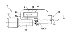
- the reference plane S is a plane that includes the drive shaft 42a of the drive motor 42 and is parallel to the vertical direction Z.
- the drive motor 42 is mounted at a position above the casing 41 so that the drive shaft 42a is parallel to the horizontal plane.
- the drive motor 42 can be attached to the casing 41 by known fastening means such as bolts, nuts and screws (not shown).
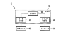
- the turning device 15 includes a control unit 52, and the drive motor 42 is driven by the control unit 52. More specifically, the control unit 52 includes a motor control unit 53 that controls energization of the drive motor 42, a cylinder control unit 54 that will be described later, and a main control unit that controls the motor control unit 53 and the cylinder control unit 54 in an integrated manner. 55.
- the control unit 52 includes a motor control unit 53 that controls energization of the drive motor 42, a cylinder control unit 54 that will be described later, and a main control unit that controls the motor control unit 53 and the cylinder control unit 54 in an integrated manner. 55.
- the drive-side sprocket 43 is attached to the casing 41 so as to be above the casing 41.
- the drive-side sprocket 43 is supported by the casing 41 so as to be rotatable around a reference line C orthogonal to the reference plane S.
- the rotor 14 described above extends parallel to the reference line C.
- a reduction mechanism 58 is provided between the drive motor 42 and the drive side sprocket 43.
- a rotor shaft (not shown) that rotates around the drive shaft 42a by driving the drive motor 42 is decelerated by the speed reduction mechanism 58, and the driving force is transmitted to the drive side sprocket 43 via the connecting shaft 58a. . That is, the drive side sprocket 43 is rotated by the drive motor 42 via the speed reduction mechanism 58.
- the driven-side sprocket 44 is on the same plane as the driving-side sprocket 43 and is disposed below the driving-side sprocket 43.
- the driven-side sprocket 44 is supported by the casing 41 so as to be rotatable around an axis parallel to the reference line C at a position separated from the driving-side sprocket 43.
- the drive side sprocket 43 and the driven side sprocket 44 are connected via a chain (annular member) 59.
- the spur ring 45 has first spur teeth 45a on the outer peripheral surface.
- the spur wheel 45 is attached integrally with the driven sprocket 44 via a connecting shaft 60 at a position separated from the wheel gear 30.
- the wheel gear 30 is disposed below the spur wheel 45.
- the pinion gear 46 has first spur teeth 45 a of the spur wheel 45 and second spur teeth 46 a that respectively mesh with the spur teeth 30 a of the wheel gear 30.
- the arm member 47 is formed by forming a steel plate into a V shape in a side view.
- the arm member 47 is supported so as to be rotatable around the connecting shaft 60 at an intermediate portion in its longitudinal direction.
- One end portion 47a of the arm member 47 extends downward from an intermediate portion of the arm member 47, and the other end portion 47b of the arm member 47 extends substantially parallel to the horizontal plane from the intermediate portion of the arm member 47.
- the pinion gear 46 is rotatably supported at one end 47 a of the arm member 47 so that the axis of the pinion gear 46 is parallel to the reference line C.
- the second spur teeth 46 a of the pinion gear 46 are always meshed with the first spur teeth 45 a of the spur ring 45.
- the gear that transmits the driving force to the wheel gear 30 on the downstream side of the driven sprocket 44 has a two-stage configuration of the spur gear 45 and the pinion gear 46.
- the moving mechanism 48 includes an air cylinder 63 as a power source, a fitting lever (moving lever) 64 whose one end 64 a is rotatably supported by the casing 41, and one end rotating to the other end 47 b of the arm member 47.
- the connecting member 65 is connected to the other end portion of the fitting lever 64 so as to be rotatable and rotatably connected to an intermediate portion in the longitudinal direction of the fitting / removing lever 64.
- the inner rod 63a of the air cylinder 63 extends to be slidable in the vertical direction Z with respect to the outer case 63b. A portion on the lower side of the inner rod 63a is accommodated in the outer case 63b.
- the outer case 63 b of the air cylinder 63 is supported by the casing 41 via a spring bush 66.
- the air cylinder 63 is configured such that the slide position of the inner rod 63a is displaced in accordance with a control command from the cylinder controller 54 (see FIG. 4).
- the cylinder controller 54 controls the position of the inner rod 63a in the vertical direction Z by controlling the opening and closing of a control valve (not shown) to supply and exhaust air in the outer case 63b.
- the upper portion of the inner rod 63a is rotatably connected to the other end portion 64b side of the portion of the fitting / removing lever 64 to which the other end portion of the connecting member 65 is connected.
- the fitting / removing lever 64 is formed in a rod shape and rotates on a plane parallel to the reference plane S.
- the moving mechanism 48 configured in this manner, when the inner rod 63a of the air cylinder 63 slides upward with respect to the outer case 63b, the inner rod 63a pushes up the other end 64b side of the fitting / removing lever 64, The fitting / removing lever 64 is disposed at the position shown in FIG. 2 rotated around the one end 64a. Then, the connecting member 65 connected to the fitting / removing lever 64 moves upward, the arm member 47 rotates around the connecting shaft 60, and the pinion gear 46 is disposed at the meshing position P ⁇ b> 1 that meshes with the wheel gear 30.
- the inner rod 63a slides downward (becomes submerged) from the state where the pinion gear 46 is disposed at the meshing position P1
- the inner rod 63a lowers the other end 64b side of the fitting / removing lever 64, and the fitting is performed.
- the release lever 64 rotates around the one end portion 64 a, and the pinion gear 46 is disposed at the retracted position P ⁇ b> 2 where it does not mesh with the wheel gear 30.
- the moving mechanism 48 can move the pinion gear 46 between the meshing position P1 and the retracted position P2 by the control command of the cylinder control unit 54.
- the chain cover 49 shown in FIGS. 1 to 3 can be attached to and detached from the casing 41 on one side D1 of the reference plane S by the above-described fastening means.
- the chain cover 49 covers the drive side sprocket 43.
- the chain cover 49 is for preventing an operator or the like from touching the drive side sprocket 43 or the chain 59.
- the aforementioned compressor 69 is connected to the other side D ⁇ b> 2 of the rotor 14 with respect to the reference plane S.
- a cylindrical coupling guard 70 is detachably attached so as to cover a connection portion between the rotor 14 and the compressor 69.
- the control unit 52 of the turning device 15 holds the inner rod 63a of the air cylinder 63 at a position where it is immersed in the outer case 63b when the steam turbine 1 is in operation.
- the drive motor 42 is in a stopped state, and the pinion gear 46 is disposed at the retracted position P2.
- the controller 52 first slides the inner rod 63a of the air cylinder 63 upward via the cylinder controller 54. Then, the arm member 47 rotates around the connecting shaft 60 via the fitting / removing lever 64 and the connecting member 65, and the pinion gear 46 moves from the retracted position P2 to the meshing position P1.
- the drive motor 42 starts to be driven.
- the rotational power of the drive motor 42 is transmitted to the wheel gear 30 via the speed reduction mechanism 58, the sprockets 43 and 44, the chain 59, the spur gear 45, and the pinion gear 46.
- the rotor 14 rotates together with the wheel gear 30.
- the rotor 14 rotates at a lower speed than during operation of the steam turbine 1.
- the coupling guard 70 may be removed during maintenance or inspection of the compressor 69. Even in this case, the coupling guard 70 is attached to the other side D2 of the reference surface S, while the chain cover 49 is attached to the one side D1 of the reference surface S. The chain cover 49 does not hinder. Further, when the control unit 52 is not in operation or the like, the operator moves the other end portion 64b of the fitting / removing lever 64 up and down to manually change the position of the pinion gear 46 between the meshing position P1 and the retreat position P2. Can be adjusted between.
- the compressor 69 is connected to the other side D2 of the reference surface S of the rotor 14, so that the connecting portion between the rotor 14 and the compressor 69 is connected.
- a coupling guard 70 is attached to the base. Even in this case, since the chain cover 49 is attached to the one side D1 of the reference surface S, it is possible to prevent the coupling guard 70 from interfering with the chain cover 49 during attachment / detachment. Since the gear for transmitting the driving force of the drive motor 42 has a two-stage configuration of the spur gear 45 and the pinion gear 46, the number of parts can be reduced and the rigidity can be reduced as compared with the conventional gear having a three-stage configuration. The length of the turning device 15 in the vertical direction Z can be suppressed and the size can be reduced. The transmission efficiency of the driving force of the driving motor 42 can be improved.
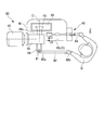
- the turning device 80 of the present embodiment has one end portion 82 a coaxial with the drive side sprocket 43 via a ratchet mechanism 81 in addition to the components of the turning device 15 of the first embodiment. And a rotation lever 82 coupled to each other.
- the ratchet mechanism 81 and the rotation lever 82 do not appear on the cross section of FIG. 5, the ratchet mechanism 81 and the rotation lever 82 are indicated by a two-dot chain line for convenience of explanation.
- the ratchet mechanism 81 is not shown in detail, it has a known configuration.
- the ratchet mechanism 81 is attached to the end of the connecting shaft 58a opposite to the drive side sprocket 43, that is, the end of the other side D2 of the reference surface S via a spacer 84.
- the ratchet mechanism 81 restricts the rotation of the one end portion 82a of the rotation lever 82 to one side around the reference line C with respect to the reference line C that is the axis of the drive side sprocket 43, that is, the spacer 84, and the reference line Allow rotation to the other side around C.
- the drive side sprocket 43 is moved to one side around the reference line C. Can only be rotated. Thereby, the rotation of the drive side sprocket 43 is transmitted, the rotor 14 rotates, and the phase of the rotor 14 can be matched.
- the rotation lever 82 is formed in a rod shape and rotates on a plane parallel to the reference plane S.
- the rotation lever 82 and the above-described fitting / removing lever 64 rotate on the same side with respect to the chain cover 49 in the direction along the reference line C.
- the operator Q operates the rotation lever 82 to rotate the rotor 14.
- the arrangement of the pinion gear 46 can be adjusted by operating the fitting / removing lever 64.
- the turning device 80 of the present embodiment it is possible to prevent the coupling guard 70 from interfering with the chain cover 49 when the coupling guard 70 is attached or detached. Since the rotation lever 82 and the fitting / removing lever 64 rotate on the same side with respect to the chain cover 49 in the direction along the reference line C, one operator Q can move both sides of the turning device 80 from one side without the chain cover 49 becoming an obstacle. The levers 64 and 82 can be easily operated.
- the concrete structure is not restricted to this embodiment, The structure of the range which does not deviate from the summary of this invention Changes, combinations, deletions, etc. are also included. Furthermore, it goes without saying that the configurations shown in the embodiments can be used in appropriate combinations.
- the driving wheel is the driving side sprocket 43
- the driven wheel is the driven side sprocket 44
- the annular member is the chain 59.
- the driving wheel may be a driving pulley
- the driven wheel may be a driven pulley
- the annular member may be a V-belt stretched over both pulleys.
- the present invention can be applied to a turning device for rotating a rotor at a low speed.
Landscapes
- Engineering & Computer Science (AREA)
- General Engineering & Computer Science (AREA)
- Mechanical Engineering (AREA)
- Gear Transmission (AREA)
- Transmission Devices (AREA)
- Pulleys (AREA)
Abstract
Description
そのため、タービンの運転停止時及び起動前には、ロータを所定時間、低速度で回転させる、いわゆるターニングを行うことで、上記ロータに曲がりが生じるのを防止している。
減速機構の下方には、上記駆動プーリと軸線方向を同じにする従動プーリ(従動輪)が配置されている。駆動プーリと従動プーリとの間には、Vベルト(環状部材)が掛け渡されている。
駆動プーリには、その同軸周りに回転する第一平歯車が一体的に取付けられている。第一平歯車の下方には、第一平歯車と軸線方向を同じにする第二平歯車が配置されている。第一平歯車と第二平歯車とは、常時噛合されている。
このように、特許文献1に記載されたターニング装置は、従動プーリよりも下流側でホイールギヤに駆動力を伝達する歯車が、第一平歯車、第二平歯車、及びピニオンギヤの3段構成となっている。
駆動プーリ及び従動プーリはチェーンカバー(カバー)で覆われ、このチェーンカバーはターニング装置のコンプレッサ側の部分に着脱可能に取付けられている。
蒸気タービンの運転が停止すると、ターニング装置の制御部によりアーム部材が傾動して、ピニオンギヤが退避位置からホイールギヤへの噛合い位置まで変位する。駆動モータが駆動すると、減速機構、駆動・従動プーリ、Vベルト、第一平歯車、第二平歯車、及びピニオンギヤを介して、駆動モータの回転動力がホイールギヤへ伝達される。そして、ホイールギヤとともにロータが回転する。この際、蒸気タービンの運転時よりも低速でロータが回転する。
本発明に係るターニング装置の態様は、ケーシングと、前記ケーシングよりも上方に取付けられた駆動モータと、前記ケーシングよりも上方であって、前記駆動モータの駆動軸上であって鉛直方向に平行な基準面に対する一方側に、前記基準面に交差する基準線周りに回転可能に支持され、前記駆動モータにより回転する駆動輪と、前記ケーシング内に配置されるとともに前記基準線に平行な軸線周りに回転可能に支持され、前記駆動輪と環状部材を介して接続された従動輪と、前記従動輪と同軸に接続され第一の平歯を有する第一の歯輪と、前記基準線に平行に延びる回転軸と同軸に設けられたホイールギヤ、及び前記第一の歯輪の前記第一の平歯にそれぞれ噛合う第二の平歯を有する第二の歯輪と、前記第二の歯輪を回転可能に支持するアーム部材と、前記アーム部材を移動させることで、前記第二の歯輪を、前記ホイールギヤに噛合う噛合い位置と、前記ホイールギヤに噛合わない退避位置との間で移動させる移動機構と、前記ケーシングに着脱可能とされ、前記駆動輪を覆うカバーと、を備え、前記回転軸の前記基準面に対する他方側に圧縮機が接続されることを特徴としている。
また、本発明に係る回転機械の態様は、上記のいずれかに記載のターニング装置を備えることを特徴としている。
以下、本発明に係る回転機械の第1実施形態を、回転機械が蒸気タービンである場合を例にとって図1から図4を参照しながら説明する。
図1に示すように、本実施形態の蒸気タービン1は、蒸気タービン1に流入する蒸気(作動流体)の量と圧力を調整する調整弁11と、圧力を保持する本体側ケーシング12と、動力を発生する動力発生部13と、発生した動力をコンプレッサ(圧縮機)69等の機械に伝達するロータ(回転軸)14と、ロータ14を軸線回りに回転可能に支持する不図示の軸受装置と、ロータ14を回転させるための本発明のターニング装置15とを備えている。
弁座20は、略円筒形状をし、その軸線はロータ14の軸線と直交している。弁座20の内径は、ロータ14に向かう方向に徐々に拡大し、先端部は蒸気室21に連通している。弁座20の蒸気室21とは反対側の端部の内面20aは、内側に向かって凸となる曲面状に形成されている。弁体19の下部の形状は、球体の一部分を形成しており、弁座20の内面20aに接離可能に設けられている。弁体19が、弁座20から離れると蒸気流路が開き、弁座20に接触すると蒸気流路が閉じられることになる。
蒸気室21は、調整弁11から流入する蒸気を動力発生部13に案内するものであり、略ドーナツ型形状をしている。蒸気室21の蒸気流路は内側に向かって行くに従って、狭くなるとともにロータ14の軸線と平行する向きに偏向している。
動翼24は、ノズル23で速度エネルギーに変換された蒸気のエネルギーをロータ14の回転エネルギーに変換する作用をする。
ロータ14は、動力発生部13で発生した動力をコンプレッサ69等の機械に伝達する作用をする。ロータ14と本体側ケーシング12との間には、蒸気等の漏れを防止する図示しないシール構造が設けられている。蒸気タービン1を作動させて仕事を終えた排気蒸気は、排気室31を通って図示しない復水器に送られる。
ターニング装置15は、図1から図3に示すように、ケーシング41と、ケーシング41に取付けられた駆動モータ42と、駆動モータ42の駆動軸42a上に規定されるとともに鉛直方向Zに平行な基準面Sに対する一方側D1に回転可能に支持された駆動側スプロケット(駆動輪)43と、ケーシング41内に回転可能に支持された従動側スプロケット(従動輪)44と、従動側スプロケット44と同軸に接続された平歯輪(第一の歯輪)45と、ロータ14に設けられたホイールギヤ30及び平歯輪45にそれぞれ噛合うピニオンギヤ(第二の歯輪)46と、ピニオンギヤ46を回転可能に支持するアーム部材47と、アーム部材47を移動させるための移動機構48と、ケーシング41に着脱可能とされたチェーンカバー(カバー)49とを備えている。
なお、図2の断面上に駆動モータ42は現れないが、説明の便宜上駆動モータ42を二点鎖線で示している。
基準面Sは、駆動モータ42の駆動軸42aを含み、鉛直方向Zに平行な平面である。
駆動モータ42は、ケーシング41よりも上方となる位置に、駆動軸42aが水平面に平行となるように取付けられている。ケーシング41に駆動モータ42は、図示しないボルト及びナットやビス等の公知の締結手段により取付けることができる。
駆動モータ42と駆動側スプロケット43との間には、減速機構58が設けられている。駆動モータ42を駆動することで駆動軸42a周りに回転する図示しないロータ軸は、その回転速度が減速機構58により減速されて、連結シャフト58aを介して駆動側スプロケット43に駆動力が伝達される。すなわち、駆動側スプロケット43は、減速機構58を介して駆動モータ42により回転する。
ピニオンギヤ46は、平歯輪45の第一の平歯45a、及びホイールギヤ30の平歯30aにそれぞれ噛合う第二の平歯46aを有している。
アーム部材47は、自身の長手方向の中間部において連結軸60周りに回転可能に支持されている。アーム部材47の一端部47aはアーム部材47の中間部から下方に延び、アーム部材47の他端部47bはアーム部材47の中間部から水平面にほぼ平行に延びている。
ピニオンギヤ46は、アーム部材47の一端部47aに、ピニオンギヤ46の軸線が基準線Cに平行となるように回転可能に支持されている。
ピニオンギヤ46の第二の平歯46aは、平歯輪45の第一の平歯45aに常時噛合している。
このように、本実施形態のターニング装置15は、従動側スプロケット44よりも下流側でホイールギヤ30に駆動力を伝達する歯車が、平歯輪45及びピニオンギヤ46の2段構成となっている。
エアシリンダ63のインナーロッド63aは、アウターケース63bに対して鉛直方向Zにスライド可能に延在されている。アウターケース63b内には、インナーロッド63aの下方側の部分が収容されている。エアシリンダ63のアウターケース63bは、スプリングブッシュ66を介してケーシング41に支持されている。
インナーロッド63aの上方側の部分は、嵌脱レバー64における連結部材65の他端部が連結された部分よりも他端部64b側に回転可能に連結されている。
この例では、嵌脱レバー64は棒状に形成され、基準面Sに平行な面上を回転する。
一方で、ピニオンギヤ46が噛合い位置P1に配置された状態からインナーロッド63aが下方にスライドした(没入した)場合には、インナーロッド63aが嵌脱レバー64の他端部64b側を引き下げ、嵌脱レバー64が一端部64a周りに回転して、ピニオンギヤ46がホイールギヤ30に噛合わない退避位置P2に配置される。
このように、移動機構48は、シリンダ制御部54の制御指令によりピニオンギヤ46を噛合い位置P1と退避位置P2との間で移動させることができる。
図1に示すように、ロータ14の基準面Sに対する他方側D2には、前述のコンプレッサ69が接続されている。ロータ14とコンプレッサ69との接続部分を覆うように、筒状のカップリングガード70が着脱可能に取付けられている。
まず、ターニング装置15の制御部52は、蒸気タービン1の運転時、エアシリンダ63のインナーロッド63aをアウターケース63bに没入された位置で保持させる。この際、駆動モータ42は停止状態となっており、ピニオンギヤ46は退避位置P2に配置されている。
また、制御部52が動作していないとき等には、嵌脱レバー64の他端部64b側を操作者が上下させることで、手動によりピニオンギヤ46の配置を噛合い位置P1と退避位置P2との間で調節することができる。
駆動モータ42の駆動力を伝達する歯車が、平歯輪45及びピニオンギヤ46の2段構成であることで、従来の歯車が3段構成である場合に比べて、部品点数を低減させるとともに剛性を高め、ターニング装置15の鉛直方向Zの長さを抑えて小型化することができる。駆動モータ42の駆動力の伝達効率を向上させることができる。
次に、本発明の第2実施形態について図5及び図6を参照しながら説明するが、前記実施形態と同一の部位には同一の符号を付してその説明は省略し、異なる点についてのみ説明する。
図5及び図6に示すように、本実施形態のターニング装置80は、第1実施形態のターニング装置15の各構成に加えて、一端部82aがラチェット機構81を介して駆動側スプロケット43と同軸に連結された回転レバー82を備えている。
なお、図5の断面上にラチェット機構81及び回転レバー82は現れないが、説明の便宜上ラチェット機構81及び回転レバー82を二点鎖線で示している。
ラチェット機構81は、駆動側スプロケット43の軸線である基準線C、すなわちスペーサ84に対して、回転レバー82の一端部82aが基準線C周りの一方側に回転するのを規制するとともに、基準線C周りの他方側に回転するのを許容する。つまり、回転レバー82の他端部82bを基準線C周りの一方側、他方側、一方側、と何度も往復するように回転させることで、駆動側スプロケット43を基準線C周りの一方側のみに回転させることができる。これにより、駆動側スプロケット43の回転が伝達されてロータ14が回転し、ロータ14の位相を合わせることができる。
回転レバー82、及び前述の嵌脱レバー64は、基準線Cに沿う方向において、チェーンカバー49に対する同じ側で回転する。
回転レバー82及び嵌脱レバー64が基準線Cに沿う方向においてチェーンカバー49に対する同じ側で回転するため、チェーンカバー49が障害となることなく、一人の操作者Qがターニング装置80の片側から両レバー64、82を容易に操作することができる。
例えば、前記第1実施形態および第2実施形態では、駆動輪が駆動側スプロケット43、従動輪が従動側スプロケット44、そして環状部材がチェーン59であるとした。しかし、駆動輪が駆動プーリ、従動輪が従動プーリ、そして環状部材が両プーリに掛け渡されたVベルトであるように構成してもよい。
回転機械が蒸気タービンであるとして説明したが、回転機械はこれに限られず、ガスタービン等でもよい。
14 ロータ(回転軸)
15、80 ターニング装置
30 ホイールギヤ
41 ケーシング
42 駆動モータ
42a 駆動軸
43 駆動側スプロケット(駆動輪)
44 従動側スプロケット(従動輪)
45 平歯輪(第一の歯輪)
45a 第一の平歯
46 ピニオンギヤ(第二の歯輪)
46a 第二の平歯
47 アーム部材
48 移動機構
49 チェーンカバー(カバー)
59 チェーン(環状部材)
64 嵌脱レバー(移動レバー)
65 連結部材
69 コンプレッサ(圧縮機)
81 ラチェット機構
82 回転レバー
82a 一端部
C 基準線
D1 一方側
D2 他方側
P1 噛合い位置
P2 退避位置
S 基準面
Z 鉛直方向
Claims (3)
- ケーシングと、
前記ケーシングよりも上方に取付けられた駆動モータと、
前記ケーシングよりも上方であって、前記駆動モータの駆動軸上であって鉛直方向に平行な基準面に対する一方側に、前記基準面に交差する基準線周りに回転可能に支持され、前記駆動モータにより回転する駆動輪と、
前記ケーシング内に配置されるとともに前記基準線に平行な軸線周りに回転可能に支持され、前記駆動輪と環状部材を介して接続された従動輪と、
前記従動輪と同軸に接続され第一の平歯を有する第一の歯輪と、
前記基準線に平行に延びる回転軸と同軸に設けられたホイールギヤ、及び前記第一の歯輪の前記第一の平歯にそれぞれ噛合う第二の平歯を有する第二の歯輪と、
前記第二の歯輪を回転可能に支持するアーム部材と、
前記アーム部材を移動させることで、前記第二の歯輪を、前記ホイールギヤに噛合う噛合い位置と、前記ホイールギヤに噛合わない退避位置との間で移動させる移動機構と、
前記ケーシングに着脱可能とされ、前記駆動輪を覆うカバーと、
を備え、
前記回転軸の前記基準面に対する他方側に圧縮機が接続されることを特徴とするターニング装置。 - 一端部がラチェット機構を介して前記駆動輪と同軸に連結された回転レバーを備え、
前記ラチェット機構は、前記駆動輪の軸線に対して前記回転レバーの一端部が前記軸線周りの一方側に回転するのを規制するとともに、前記軸線周りの他方側に回転するのを許容し、
前記移動機構は、
一端部が前記ケーシングに回転可能に支持された移動レバーと、
前記移動レバー及び前記アーム部材にそれぞれ連結され、前記移動レバーが回転したときに前記アーム部材が移動するように構成された連結部材と、
を有し、
前記回転レバー及び前記移動レバーは、前記基準線に沿う方向において、前記カバーに対する同じ側で回転することを特徴とする請求項1に記載のターニング装置。 - 請求項1又は2に記載のターニング装置を備えることを特徴とする回転機械。
Priority Applications (5)
| Application Number | Priority Date | Filing Date | Title |
|---|---|---|---|
| EP14881100.3A EP2987969B1 (en) | 2014-01-28 | 2014-01-28 | Turning device and rotary machine |
| US14/894,293 US10072529B2 (en) | 2014-01-28 | 2014-01-28 | Turning device and rotary machine |
| CN201480028846.4A CN105229267B (zh) | 2014-01-28 | 2014-01-28 | 转动装置及旋转机械 |
| JP2015559638A JP6058167B2 (ja) | 2014-01-28 | 2014-01-28 | ターニング装置及び回転機械 |
| PCT/JP2014/051756 WO2015114730A1 (ja) | 2014-01-28 | 2014-01-28 | ターニング装置及び回転機械 |
Applications Claiming Priority (1)
| Application Number | Priority Date | Filing Date | Title |
|---|---|---|---|
| PCT/JP2014/051756 WO2015114730A1 (ja) | 2014-01-28 | 2014-01-28 | ターニング装置及び回転機械 |
Publications (1)
| Publication Number | Publication Date |
|---|---|
| WO2015114730A1 true WO2015114730A1 (ja) | 2015-08-06 |
Family
ID=53756351
Family Applications (1)
| Application Number | Title | Priority Date | Filing Date |
|---|---|---|---|
| PCT/JP2014/051756 Ceased WO2015114730A1 (ja) | 2014-01-28 | 2014-01-28 | ターニング装置及び回転機械 |
Country Status (5)
| Country | Link |
|---|---|
| US (1) | US10072529B2 (ja) |
| EP (1) | EP2987969B1 (ja) |
| JP (1) | JP6058167B2 (ja) |
| CN (1) | CN105229267B (ja) |
| WO (1) | WO2015114730A1 (ja) |
Cited By (1)
| Publication number | Priority date | Publication date | Assignee | Title |
|---|---|---|---|---|
| JP2020133556A (ja) * | 2019-02-22 | 2020-08-31 | 三菱重工コンプレッサ株式会社 | ギアド圧縮機の位相調整システム、ギアド圧縮機の位相調整治具、及びギアド圧縮機の位相調整方法 |
Families Citing this family (4)
| Publication number | Priority date | Publication date | Assignee | Title |
|---|---|---|---|---|
| ES2803975T3 (es) * | 2017-02-08 | 2021-02-01 | Parker Hannificn Corp | Dispositivo exoesquelético de movilidad de piernas con un mecanismo accionador mejorado |
| KR101987311B1 (ko) * | 2017-12-14 | 2019-06-10 | 한국남부발전(주) | 가스 터빈 로터 보조 터닝장치 |
| CN108061138B (zh) * | 2017-12-19 | 2024-05-10 | 深圳市新嘉拓自动化技术有限公司 | 一种可伸缩式卷轴驱动装置 |
| CN112356049A (zh) * | 2020-12-18 | 2021-02-12 | 华南理工大学广州学院 | 一种传动结构 |
Citations (7)
| Publication number | Priority date | Publication date | Assignee | Title |
|---|---|---|---|---|
| JPH0370802A (ja) * | 1989-08-11 | 1991-03-26 | Hitachi Ltd | ターニング装置の制御方法 |
| JPH0454360A (ja) * | 1990-06-22 | 1992-02-21 | Masanori Tetsuyama | 差動歯車式増減速装置 |
| JP2000246082A (ja) * | 1999-03-03 | 2000-09-12 | Asahi Chem Res Lab Ltd | 混合攪拌装置 |
| JP2003293706A (ja) * | 2002-04-01 | 2003-10-15 | Mitsubishi Heavy Ind Ltd | ターニング装置及びターニング装置の運転制御方法 |
| JP2012177328A (ja) * | 2011-02-25 | 2012-09-13 | Mitsubishi Heavy Industries Compressor Corp | ターニング装置 |
| JP2012241536A (ja) * | 2011-05-16 | 2012-12-10 | Mitsubishi Heavy Ind Ltd | ロータ変形防止方法およびロータ変形防止装置 |
| WO2013124979A1 (ja) | 2012-02-22 | 2013-08-29 | 三菱重工コンプレッサ株式会社 | ターニング装置、および、回転機械 |
Family Cites Families (10)
| Publication number | Priority date | Publication date | Assignee | Title |
|---|---|---|---|---|
| US2747423A (en) * | 1954-06-04 | 1956-05-29 | Sanders Morris | Gear disengaging devices for worm gears |
| US2949730A (en) * | 1957-02-25 | 1960-08-23 | Allis Chalmers Mfg Co | Elastic fluid turbine two speed motor control system |
| US3919894A (en) * | 1974-09-30 | 1975-11-18 | Gen Electric | Pre-engagement turning gear |
| JPS5614809A (en) * | 1979-07-13 | 1981-02-13 | Hitachi Ltd | Oil turbine type turning apparatus |
| US4433589A (en) * | 1981-08-14 | 1984-02-28 | Black & Decker Inc. | Gear reduction arrangement for variable speed power driven tool |
| JP4158790B2 (ja) * | 2005-07-12 | 2008-10-01 | ブラザー工業株式会社 | 搬送装置及び画像形成装置 |
| DE102008046347A1 (de) * | 2008-09-09 | 2010-03-11 | Siemens Aktiengesellschaft | Rotordrehvorrichtung für eine Dampfturbine |
| CN101718227A (zh) | 2009-11-01 | 2010-06-02 | 韩凤琳 | 热流涡轮机 |
| US8683886B2 (en) * | 2011-06-08 | 2014-04-01 | First Dome Corporation | Sliding auxiliary device |
| JP5717668B2 (ja) | 2012-02-20 | 2015-05-13 | 株式会社東芝 | ターニング装置およびターニング方法 |
-
2014
- 2014-01-28 JP JP2015559638A patent/JP6058167B2/ja active Active
- 2014-01-28 CN CN201480028846.4A patent/CN105229267B/zh not_active Expired - Fee Related
- 2014-01-28 US US14/894,293 patent/US10072529B2/en active Active
- 2014-01-28 WO PCT/JP2014/051756 patent/WO2015114730A1/ja not_active Ceased
- 2014-01-28 EP EP14881100.3A patent/EP2987969B1/en active Active
Patent Citations (7)
| Publication number | Priority date | Publication date | Assignee | Title |
|---|---|---|---|---|
| JPH0370802A (ja) * | 1989-08-11 | 1991-03-26 | Hitachi Ltd | ターニング装置の制御方法 |
| JPH0454360A (ja) * | 1990-06-22 | 1992-02-21 | Masanori Tetsuyama | 差動歯車式増減速装置 |
| JP2000246082A (ja) * | 1999-03-03 | 2000-09-12 | Asahi Chem Res Lab Ltd | 混合攪拌装置 |
| JP2003293706A (ja) * | 2002-04-01 | 2003-10-15 | Mitsubishi Heavy Ind Ltd | ターニング装置及びターニング装置の運転制御方法 |
| JP2012177328A (ja) * | 2011-02-25 | 2012-09-13 | Mitsubishi Heavy Industries Compressor Corp | ターニング装置 |
| JP2012241536A (ja) * | 2011-05-16 | 2012-12-10 | Mitsubishi Heavy Ind Ltd | ロータ変形防止方法およびロータ変形防止装置 |
| WO2013124979A1 (ja) | 2012-02-22 | 2013-08-29 | 三菱重工コンプレッサ株式会社 | ターニング装置、および、回転機械 |
Cited By (2)
| Publication number | Priority date | Publication date | Assignee | Title |
|---|---|---|---|---|
| JP2020133556A (ja) * | 2019-02-22 | 2020-08-31 | 三菱重工コンプレッサ株式会社 | ギアド圧縮機の位相調整システム、ギアド圧縮機の位相調整治具、及びギアド圧縮機の位相調整方法 |
| JP7221727B2 (ja) | 2019-02-22 | 2023-02-14 | 三菱重工コンプレッサ株式会社 | ギアド圧縮機の位相調整システム、ギアド圧縮機の位相調整治具、及びギアド圧縮機の位相調整方法 |
Also Published As
| Publication number | Publication date |
|---|---|
| JP6058167B2 (ja) | 2017-01-11 |
| JPWO2015114730A1 (ja) | 2017-03-23 |
| CN105229267B (zh) | 2018-01-12 |
| EP2987969A4 (en) | 2016-04-27 |
| EP2987969A1 (en) | 2016-02-24 |
| CN105229267A (zh) | 2016-01-06 |
| US10072529B2 (en) | 2018-09-11 |
| EP2987969B1 (en) | 2018-03-07 |
| US20160108760A1 (en) | 2016-04-21 |
Similar Documents
| Publication | Publication Date | Title |
|---|---|---|
| JP6058167B2 (ja) | ターニング装置及び回転機械 | |
| JP5984910B2 (ja) | ターニング装置、および、回転機械 | |
| EP2557033B1 (en) | Modular counter rotating propeller system | |
| JP6058028B2 (ja) | 蒸気弁及び蒸気タービン | |
| JP5490880B2 (ja) | ターボプロップのファンブレードのピッチを制御する可動アクチュエータ装置 | |
| KR101872854B1 (ko) | 호버링 가능한 항공기용의 유성 기어 트레인 | |
| CA2688727A1 (en) | Bypass air scoop for gas turbine engine | |
| KR101931111B1 (ko) | 동력 전달을 위한 장치 | |
| US20180306121A1 (en) | Turbine engine with fan and reduction of speed on the shaft of the power turbine | |
| WO2003046346A1 (en) | Variable turbocharger | |
| US20160207609A1 (en) | Device for supplying hydraulic fluid to a ram and mechanism for controlling the pitch of the blades of a turbine engine propeller comprising the ram | |
| JP2017095082A (ja) | プロペラピッチを制御するためのシステム及び方法 | |
| JP2015102181A (ja) | 波動歯車減速機 | |
| JP2017100701A (ja) | プロペラピッチ制御システム及び方法 | |
| JP6298529B2 (ja) | 可変静翼装置のメンテナンス方法及び可変静翼装置 | |
| RU2569801C2 (ru) | Уплотнительное устройство, имеющее кожух для прохода соединительной тяги системы управления шагом для лопастей вентилятора турбовинтового двигателя сквозь перегородку | |
| JP6222615B2 (ja) | ターニング装置 | |
| EP3434882B1 (en) | Air turbine starter | |
| CN114991990A (zh) | 一种核心机排气喉道面积调节装置 | |
| EP3112609B1 (en) | Electric actuator for engine control | |
| CN217585306U (zh) | 一种高温推板炉用加热装置 | |
| CN214466204U (zh) | 一种曲轴式多回转气动大口径双闸板闸阀 | |
| EP3364019B1 (en) | Assembly of blade and rotor, and power generation device | |
| CN116608015A (zh) | 一种发电厂用汽轮机调门装置 | |
| CN103742253B (zh) | 废气流通量调控型涡轮增压器 |
Legal Events
| Date | Code | Title | Description |
|---|---|---|---|
| WWE | Wipo information: entry into national phase |
Ref document number: 201480028846.4 Country of ref document: CN |
|
| ENP | Entry into the national phase |
Ref document number: 2015559638 Country of ref document: JP Kind code of ref document: A |
|
| 121 | Ep: the epo has been informed by wipo that ep was designated in this application |
Ref document number: 14881100 Country of ref document: EP Kind code of ref document: A1 |
|
| WWE | Wipo information: entry into national phase |
Ref document number: 2014881100 Country of ref document: EP |
|
| WWE | Wipo information: entry into national phase |
Ref document number: 14894293 Country of ref document: US |
|
| NENP | Non-entry into the national phase |
Ref country code: DE |