WO2015114933A1 - カメラおよびアダプタ - Google Patents
カメラおよびアダプタ Download PDFInfo
- Publication number
- WO2015114933A1 WO2015114933A1 PCT/JP2014/081521 JP2014081521W WO2015114933A1 WO 2015114933 A1 WO2015114933 A1 WO 2015114933A1 JP 2014081521 W JP2014081521 W JP 2014081521W WO 2015114933 A1 WO2015114933 A1 WO 2015114933A1
- Authority
- WO
- WIPO (PCT)
- Prior art keywords
- adapter
- body mount
- contact
- lens
- reference surface
- Prior art date
- Legal status (The legal status is an assumption and is not a legal conclusion. Google has not performed a legal analysis and makes no representation as to the accuracy of the status listed.)
- Ceased
Links
Images








Classifications
-
- G—PHYSICS
- G03—PHOTOGRAPHY; CINEMATOGRAPHY; ANALOGOUS TECHNIQUES USING WAVES OTHER THAN OPTICAL WAVES; ELECTROGRAPHY; HOLOGRAPHY
- G03B—APPARATUS OR ARRANGEMENTS FOR TAKING PHOTOGRAPHS OR FOR PROJECTING OR VIEWING THEM; APPARATUS OR ARRANGEMENTS EMPLOYING ANALOGOUS TECHNIQUES USING WAVES OTHER THAN OPTICAL WAVES; ACCESSORIES THEREFOR
- G03B17/00—Details of cameras or camera bodies; Accessories therefor
- G03B17/02—Bodies
- G03B17/12—Bodies with means for supporting objectives, supplementary lenses, filters, masks, or turrets
- G03B17/14—Bodies with means for supporting objectives, supplementary lenses, filters, masks, or turrets interchangeably
-
- G—PHYSICS
- G03—PHOTOGRAPHY; CINEMATOGRAPHY; ANALOGOUS TECHNIQUES USING WAVES OTHER THAN OPTICAL WAVES; ELECTROGRAPHY; HOLOGRAPHY
- G03B—APPARATUS OR ARRANGEMENTS FOR TAKING PHOTOGRAPHS OR FOR PROJECTING OR VIEWING THEM; APPARATUS OR ARRANGEMENTS EMPLOYING ANALOGOUS TECHNIQUES USING WAVES OTHER THAN OPTICAL WAVES; ACCESSORIES THEREFOR
- G03B17/00—Details of cameras or camera bodies; Accessories therefor
- G03B17/56—Accessories
- G03B17/566—Accessory clips, holders, shoes to attach accessories to camera
-
- H—ELECTRICITY
- H04—ELECTRIC COMMUNICATION TECHNIQUE
- H04N—PICTORIAL COMMUNICATION, e.g. TELEVISION
- H04N23/00—Cameras or camera modules comprising electronic image sensors; Control thereof
- H04N23/50—Constructional details
- H04N23/51—Housings
-
- H—ELECTRICITY
- H04—ELECTRIC COMMUNICATION TECHNIQUE
- H04N—PICTORIAL COMMUNICATION, e.g. TELEVISION
- H04N23/00—Cameras or camera modules comprising electronic image sensors; Control thereof
- H04N23/60—Control of cameras or camera modules
- H04N23/66—Remote control of cameras or camera parts, e.g. by remote control devices
- H04N23/663—Remote control of cameras or camera parts, e.g. by remote control devices for controlling interchangeable camera parts based on electronic image sensor signals
Definitions
- the present disclosure relates to an interchangeable lens camera and an adapter used for the camera.
- the lens is attached to an opening called a body mount provided on the front of the body.
- One of the characteristics of body mount is the flange back.
- the flange back is a distance between the reference surface of the body mount, that is, the surface where the rear end of the lens contacts the body mount, and the imaging surface of the image sensor.
- Each body or body mount has a unique flange back.
- Interchangeable lenses are also designed for the body or body mount flange back on which they are mounted.
- the method of adjusting the flange back using the intermediate adapter in this way cannot be applied when it is desired to use a lens having a flange back shorter than the flange back inherent to the body. If the entire body mount is replaced, it will not be possible to cope with such a case, but replacement of the entire body mount is difficult and not practical.
- a camera includes a body mount having a first reference surface and having a first flange back between the first reference surface and the imaging surface, and the second reference surface is provided on the first reference surface. And an adapter having a second flange back shorter than the first flange back can be mounted between the second reference surface and the imaging surface.
- An adapter is attachable to a first reference surface of a body mount having a first reference surface and having a first flange back between the first reference surface and the imaging surface. It has two reference planes and has a second flange back shorter than the first flange back between the second reference plane and the imaging plane.
- the first reference surface of the body mount has the second reference surface, and the second reference surface is between the second reference surface and the imaging surface.
- the first reference surface of the body mount has the second reference surface and is between the second reference surface and the imaging surface. It is possible to mount an adapter having a second flange back shorter than the first flange back. Therefore, it is possible to use a lens having a second flange back shorter than the first flange back unique to the body without exchanging the entire body mount. Note that the effects described here are not necessarily limited, and may be any effects described in the present disclosure.
- FIG. 2 is a side view illustrating an appearance of a camera body according to a first embodiment of the present disclosure as viewed from the right side.
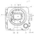
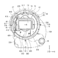
- FIG. 2 is a front view showing the external appearance which looked at the body shown in FIG. 4 from the front front. It is a front view showing the structure which took out the body mount and front part shown in FIG.
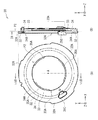
- FIG. 4 is a front view of the adapter according to the first embodiment of the present disclosure and a cross-sectional view taken along the line VIIB-VIIB of the front view.
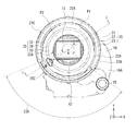
- FIG. It is a rear view of the adapter shown in FIG. It is a front view showing the state which mounted
- FIG. 10 is a cross-sectional view taken along line XX in FIG. 9. It is sectional drawing which expands and represents a part of FIG. 6 is a front view of an adapter according to a second embodiment of the present disclosure, and a cross-sectional view taken along the line XIIB-XIIB of the front view.
- FIG. 13 is a front view illustrating a state in which the attachment / detachment lever of the adapter is in an initial position in a state where the adapter illustrated in FIG. 12 is attached to the body mount illustrated in FIG. 6.
- FIG. 13 is a front view showing a state in which the attachment / detachment lever of the adapter is in the fastening position in a state where the adapter shown in FIG. 12 is attached to the body mount shown in FIG. 6.
- FIG. 16 is a cross-sectional view taken along line XVI-XVI in FIG. 15. It is sectional drawing which expands and represents a part of FIG.
- FIG. 19 is a side view illustrating a first application example of a camera according to an embodiment of the present disclosure, and is a side view illustrating a state where a cinema photographing lens is attached to the adapter illustrated in FIG. 18. It is a side view showing the 2nd example of application of the camera of one embodiment of this indication, and is attached to the body mount concerning a 1st embodiment of this indication.
- FIG. 11 is a side view showing the state which mounted
- 11 is a front view illustrating a configuration of a front portion of a body according to Modification Example 1.
- 10 is a front view illustrating a configuration of a front portion of a body according to Modification Example 2.
- FIG. 10 is a front view illustrating a configuration of a front portion of a body according to Modification 3.
- FIG. 10 is a front view illustrating a configuration of a front portion of a body according to Modification Example 4.
- Modification 1 (example in which the first contact is arranged upward and to the right and the second contact is arranged upward when the body mount is viewed from the front front) 7).
- Modification 2 (example in which the first contact is located on the upper and right sides and the second contact is located on the left side when the body mount is viewed from the front front) 8).
- Modification 3 (example in which the first contact is arranged upward and to the right, and the second contact is arranged obliquely to the left when the body mount is viewed from the front front) 9.
- Modification 4 (Example in which the first contact is on the left and the second contact is on the upper side when the body mount is viewed from the front in front)
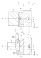
- FIG. 1 schematically shows a method of adjusting a flange back in a camera according to an embodiment of the present disclosure.
- the camera 1 has a body mount 20 on the front surface of the body 10, and the first lens 2 ⁇ / b> A is attached to the body mount 20.
- An imaging element 11 is built in the body 10.
- the body mount 20 is provided on the front surface portion 12 of the body 10.
- An optical component 13 is disposed on the front surface portion 12 so as to face the imaging element 11.
- the front surface portion 12 is a set of members (optical component 13, first contact point 41, second contact point 42, these supporting members, and chassis member 16) other than the body mount 20 provided on the front surface of the body 10. Refers to the body.
- Z represents the optical axis direction.
- the optical axis A is a line that passes through the center of the first lens 2 ⁇ / b> A, the optical component 13, and the image sensor 11.
- the first lens 2A side (lens side) is the front and the body 10 side is the rear.
- X represents the left-right direction when the body mount 20 is viewed from the front front
- Y represents the vertical direction when the body mount 20 is viewed from the front front.
- the body 10 has a first flange back FB1.
- the first flange back FB1 is a distance in the optical axis direction Z between the first reference plane P1 and the imaging plane P11 of the body mount 20, and is a value specific to each body 10.
- the first reference plane P1 is a surface where the body mount 20 and the rear end portion of the first lens 2A are in contact.
- the imaging surface P11 corresponds to, for example, a surface on which light enters the photodiode of the imaging element 11.
- the first lens 2A corresponding to the first flange back FB1 unique to the body 10 is attached to the body 10.
- FIG. 1B shows the case corresponding to the third lens 2C having the third flange back FB3 longer than the first flange back FB1.
- the adapter 30C is attached to the body mount 20, and the maximum thickness D30C in the optical axis direction Z of the adapter 30C is added to the first flange back FB1.
- the maximum thickness D30C of the adapter 30C is a distance in the optical axis direction Z between the mounting surface 31C and the third reference surface P3.
- the mounting surface 31 ⁇ / b> C is a surface in contact with the first reference surface P ⁇ b> 1 in a state of being mounted on the first reference surface P ⁇ b> 1 of the body mount 20.
- the third reference surface P3 is a surface on which the third lens 2C is mounted.
- the third reference surface P3 is located in front of the mounting surface 31C in the optical axis direction Z, that is, on the third lens 2C side. Therefore, when this adapter 30C is used, the distance between the third reference plane P3 and the imaging plane P11 in the optical axis direction Z is longer than that of the first flange back FB1. Therefore, this adapter 30C is difficult to cope with the second lens having the second flange back shorter than the first flange back FB1.
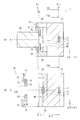
- FIG. 2 schematically illustrates a cross-sectional configuration of the adapter 30 according to an embodiment of the present disclosure.
- the adapter 30 has the first reference surface P1 described above, and the body mount 20 having the first flange back FB1 between the first reference surface P1 and the imaging surface P11.
- the first reference plane P1 can be mounted.
- the adapter 30 has a second flange back FB2 having a second reference surface P2 and shorter than the first flange back FB1 between the second reference surface P2 and the imaging surface P11.
- the second reference surface P2 is a surface on which the second lens 2B (see FIG. 2A) having the second flange back FB2 is mounted.
- the camera 1 can support the second lens 2B having the second flange back FB2 shorter than the first flange back FB1 unique to the body 10 without exchanging the entire body mount 20.
- the adapter 30 has a mounting surface 31 in contact with the first reference surface P1 in a state of being mounted on the first reference surface P1 of the body mount 20.
- the second reference plane P2 is preferably located on the imaging plane P11 side with respect to the mounting surface 31 in the optical axis direction Z. In this way, the second lens 2B having the second flange back FB2 shorter than the first flange back FB1 unique to the body 10 can be attached to the body mount 20 via the adapter 30. .
- Such an adapter 30 has an outer peripheral portion 32 and an inner peripheral portion 33 as shown in FIG.
- An opening 33 ⁇ / b> A is provided on the inner peripheral side of the adapter 30.
- the outer peripheral portion 32 is a portion that is attached to the first reference surface P1 of the body mount 20, and has the above-described attachment surface 31.
- the inner peripheral part 33 is provided concentrically inside the outer peripheral part 32 and has a second reference plane P2.
- the outer peripheral portion 32 and the inner peripheral portion 33 are connected in the optical axis direction Z by the intermediate portion 34.
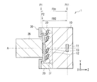
- the inner peripheral portion 33 is surrounded by the body mount 20 and the front surface portion 12 of the body 10 in a state where the outer peripheral portion 32 is mounted on the first reference plane P1 of the body mount 20, as shown in FIG. Enter the mount space MS.
- the front surface portion 12 of the body 10 is designed in correspondence with the mounting of the first lens 2A having the first flange back FB1, and it is normal that the adapter 30 is not assumed to enter deeply into the mount space MS. It is. Therefore, as shown in FIG. 3, there is a possibility that an interference IF between the adapter 30 and the front surface portion 12 of the body 10 occurs.
- the front surface portion 12 of the body 10 is configured to avoid interference with the adapter 30 attached to the first reference plane P1. It is preferable that Specifically, in the optical component 13 disposed on the front surface portion 12, the distance D13 in the optical axis direction Z between the optical component 13 and the imaging surface P11 is shortened in order to avoid interference between the optical component 13 and the adapter 30. It is preferable. Further, it is preferable that the front surface portion 12 is retracted rearward in the optical axis direction Z on the assumption that the adapter 30 is attached.
- the retraction amount R12 at this time avoids interference with the adapter 30 depending on the difference between the first flange back FB1 unique to the body 10 and the second flange back FB2 of the adapter 30 or the second lens 2B to be mounted. A possible value is preferable. By doing so, it is possible to provide a further margin in the mount space MS and more reliably avoid interference with the adapter 30. Details of such interference avoidance design of the front surface portion 12 will be described in a first embodiment described later. It should be noted that components other than the optical component 13 arranged on the front surface portion 12 may be located at the same position or substantially the same position as the optical component 13 in the optical axis direction Z, or as shown in FIG. Components other than the optical component 13 arranged at 12 may be further retracted rearward in the optical axis direction Z than the optical component 13.
- FIG. 4 illustrates an appearance of the body 10 of the camera 1 according to the first embodiment of the present disclosure as viewed from the right side.
- FIG. 5 shows an appearance of the body 10 shown in FIG. 4 as viewed from the front front.
- the camera 1 is a cinema shooting camera, for example, and has a body mount 20 at the forefront in the optical axis direction Z of the body 10.
- the body 10 has an exterior member 14, and an imaging element 11 (not shown in FIG. 4, see FIG. 2) is built in the exterior member 14.
- buttons and adjustment buttons On each surface of the exterior member 14, in addition to the recording start button 14A, the menu selection button 14B, and the side panel 14C, various operation buttons and adjustment buttons, an accessory mounting portion such as a viewfinder, an external memory storage portion, a USB connection portion, A battery connection portion and the like are provided as appropriate.
- the body mount 20 includes a first lens 2A (see FIG. 1A), an adapter 30C (see FIG. 1B) or an adapter 30 (see FIG. 2A) and the body 10. It becomes a connection part.
- the body mount 20 is provided at the upper center of the front surface of the exterior member 14 of the body 10.
- An optical component 13 is provided at the center inside the body mount 20.
- An imaging element 11 (not shown in FIG. 5, see FIG. 2A) is arranged behind the optical component 13 in the optical axis direction Z.
- a first contact 41 and a second contact 42 are provided in an area around the optical component 13 inside the body mount 20.
- an operation dial 15 is provided on the lower right front portion of the exterior member 14 of the body 10.
- the operation dial 15 is an operation unit for a user to switch an optical component such as an ND filter (a neutral density filter) disposed between the optical component 13 and the image sensor 11.
- the operation dial 15 is not limited to the rotary type (dial type) as in the present embodiment, and may be a push type such as an operation button.
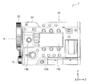
- FIG. 6 shows a configuration in which the body mount 20 and the front surface portion 12 shown in FIG. 5 are taken out from the exterior member 14 and viewed from the front front side.
- the front surface portion 12 has a chassis member 16.
- the body mount 20 occupies a region from the left side to the upper side of the chassis member 16.
- the chassis member 16 has a storage portion 16A below the body mount 20 and obliquely downward to the right.
- three to four turrets (not shown) that hold optical components such as the above-described ND filters are accommodated in the accommodating portion 16A.
- the above-described operation dial 15 is provided on the lower right side of the storage portion 16A. When the user turns the operation dial 15, the turret is rotated and optical components such as an ND filter are switched.
- the body mount 20 employs a spigot method as a mounting method of the first lens 2A, the adapter 30C, or the adapter 30, and has, for example, a mounting ring 21, a holding ring 22 and a fastening ring 23 in order from the inner peripheral side. .
- FIG. 6 only the mounting ring 21 and the holding ring 22 are shown, and the fastening ring 23 is not shown in FIG. 6 but shown in FIG.
- the mounting ring 21 is a portion on which the rear end portion of the first lens 2A, the adapter 30C or the adapter 30 is seated, and has the above-described first reference plane P1.
- the first reference surface P1 is a surface on which the rear end portion of the first lens 2A, the adapter 30C, or the adapter 30 is mounted.
- the distance in the optical axis direction Z between the first reference plane P1 and the imaging plane P11 is a first flange back FB1 (see FIG. 1A) unique to the body 10.
- the body 10 is basically mounted with a first lens 2A (see FIG. 1A) adapted to the first flange back FB1.
- the holding ring 22 is a portion that holds the rear end portion of the first lens 2A, the adapter 30C, or the adapter 30.
- the retaining ring 22 has claws 22A at three locations in the circumferential direction.
- the claw 22A protrudes above the first reference plane P1 of the mounting ring 21, and can be held by sandwiching the rear end portion of the first lens 2A or the adapter 30 between the first reference plane P1 and the claw 22A. It is possible.
- the fastening ring 23 fastens and fixes the first lens 2A, the adapter 30C or the adapter 30 and the body mount 20 by rotating around the optical axis A together with the holding ring 22. It is preferable that an uneven slip stopper 23 ⁇ / b> A is provided on the outer surface of the fastening ring 23 so that the user can easily grip and turn the fastening ring 23.
- the optical component 13 is, for example, a glass plate member having a protection function for the image sensor 11 and an appropriate optical function.
- the optical component 13 has, for example, a rectangular shape that is long in one direction, and is disposed horizontally in the center of a circular region surrounded by the body mount 20. Needless to say, the image pickup device 11 is also arranged in a horizontally long manner like the optical component 13.
- the optical component 13 is supported by the optical component support member 17.
- the optical component support member 17 is fixed to the chassis member 16 by screws 17A and 17B.
- the first contact 41 is connected to the body 10 and the first lens 2A, which is attached to the first reference plane P1 and has the first flange back FB1 unique to the body 10.
- the first contact 41 supplies, for example, a contact for supplying power from the body 10 to the first lens 2A attached to the body 10, and a drive signal for driving the first lens 2A from the body 10 to the first lens 2A.
- a set of contacts including at least a contact.
- the first contact 41 is arranged on the left side in the circumferential direction of the body mount 20 (circumferential direction with the optical axis A as the center) when the body mount 20 is viewed from the front front.
- the first contact point 41 is arranged in an arc shape along the short side on the left side of the optical component 13.
- the first contact 41 is supported by a first contact support member 41A.
- the first contact support member 41A is fixed to and supported by the chassis member 16 with screws 41B and 41C.
- the second contact 42 is connected to the body 10 and the second lens 2B having the second flange back FB2 mounted on the second reference plane P2.
- the second contact 42 supplies, for example, a contact for supplying power from the body 10 to the second lens 2B attached to the body 10 and a drive signal for driving the second lens 2B from the body 10 to the second lens 2B.
- a set of contacts including at least a contact.
- the second contact 42 is disposed below in the circumferential direction of the body mount 20 when the body mount 20 is viewed from the front front. In other words, the second contact 42 is arranged in an arc shape along the lower long side of the optical component 13.
- the second contact 42 is supported by a second contact support member 42A.
- the second contact support member 42A is fixed to and supported by the chassis member 16 by screws 42B and 42C.
- the second contact 42 is preferably located on the inner peripheral side of the first contact 41 in the radial direction of the body mount 20 (radial direction with respect to the optical axis A).
- the second contact 42 is exposed from the opening 33A on the inner peripheral side of the adapter 30 in a state where the adapter 30 is mounted on the first reference plane P1, and the second contact 42 and the second lens 2B are exposed.
- the first contact 41 hidden by the adapter 30 it is possible to easily recognize that the first lens 2 ⁇ / b> A is not in a state where the first lens 2 ⁇ / b> A can be attached, thereby making it difficult to make a mistake in attaching the lens. Is possible.
- the first contact 41 and the second contact 42 are preferably arranged at different positions in the circumferential direction of the body mount 20.
- the configurations of the first contact support member 41A and the second contact support member 42A can be simplified.
- the first contact 41 and the second contact 42 may be arranged at the same position or substantially the same position in the circumferential direction of the body mount 20. A modification of the arrangement of the first contact 41 and the second contact 42 will be described later.
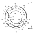
- FIG. 7A illustrates a configuration of the adapter 30 according to the first embodiment of the present disclosure as viewed from the front front.
- FIG. 7B illustrates a cross-sectional configuration taken along the line VIIB-VIIB in FIG.
- the adapter 30 has the first reference surface P1 described above, and the body mount 20 having the first flange back FB1 between the first reference surface P1 and the imaging surface P11.
- the first reference plane P1 can be mounted.
- the adapter 30 has a second flange back FB2 having a second reference surface P2 and shorter than the first flange back FB1 between the second reference surface P2 and the imaging surface P11.
- the second reference surface P2 is a surface on which the second lens 2B (see FIG. 2A) having the second flange back FB2 is mounted.
- the camera 1 can support the second lens 2B having the second flange back FB2 shorter than the first flange back FB1 unique to the body 10 without exchanging the entire body mount 20.
- the adapter 30 is for fixing the second lens 2B having the second flange back FB2 to the body mount 20, for example, as shown in FIGS. 7A and 7B.
- the outer peripheral portion 32, the inner peripheral portion 33, and the intermediate portion 34 are provided.
- a circular opening 33 ⁇ / b> A is provided on the inner peripheral side of the adapter 30.
- the diameter of the adapter 30 is smaller than the diameter of the body mount 20.
- the outer peripheral portion 32 is a portion that is attached to the first reference surface P ⁇ b> 1 of the body mount 20, and has a mounting surface 31.
- the mounting surface 31 is a surface in contact with the first reference surface P1 in a state where the mounting surface 31 is mounted on the first reference surface P1 of the body mount 20.
- the outer peripheral portion 32 has outer claws 32A for attachment to the body mount 20 at three locations in the circumferential direction.
- the inner peripheral portion 33 is provided concentrically inside the outer peripheral portion 32 and has a second reference plane P2.
- the second reference plane P2 is preferably located on the imaging plane P11 side with respect to the mounting surface 31 in the optical axis direction Z. In this way, the second lens 2B having the second flange back FB2 shorter than the first flange back FB1 unique to the body 10 can be attached to the body mount 20 via the adapter 30. .
- the intermediate part 34 is a step part that connects the outer peripheral part 32 and the inner peripheral part 33 in the optical axis direction Z.
- the intermediate portion 34 preferably has an inclined surface 34 ⁇ / b> A that connects the outer peripheral portion 32 and the inner peripheral portion 33.
- FIG. 8 shows a configuration of the adapter 30 shown in FIG. 7 viewed from the back side.
- the adapter 30 employs a bayonet system as a method of attaching the second lens 2B, and includes, for example, an inner claw 35A, a bayonet mechanism 35B, and a second lens release button 35C.
- the inner claw 35A is for mounting the second lens 2B on the second reference plane P2.
- the inner claws 35 ⁇ / b> A are provided at three locations in the circumferential direction of the opening 33 ⁇ / b> A of the inner peripheral portion 33.
- the bayonet mechanism 35B is a spring mechanism provided on the back side of the inner claw 35A.
- the bayonet mechanism 35B presses the second lens 2B against the second reference plane P2, and the displacement in the optical axis direction Z of the second lens 2B. And the position shift is suppressed.
- the second lens release button 35C is a push button for removing the second lens 2B from the adapter 30 as shown in FIG.
- the second lens release button 35 ⁇ / b> C is provided diagonally to the left of the outer peripheral portion 32 and the intermediate portion 34.
- the second lens release button 35C preferably protrudes from the front surface 32A of the outer peripheral portion 32 to the second lens 2B side in the optical axis direction Z. In this way, the user can easily press the second lens release button 35C with the belly of the finger instead of the tip of the fingernail, and the usability is improved.
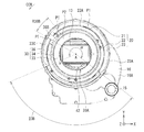
- FIG. 9 shows a configuration in which such an adapter 30 is mounted on the body mount 20 shown in FIG. 6 as viewed from the front front of the body mount 20.
- FIG. 9 also shows the fastening ring 23 omitted in FIG.
- the first contact 41 is hidden by the adapter 30 and the second contact 42 is exposed from the opening 33A on the inner peripheral side of the adapter 30.
- the second contact 42 is exposed from the opening 33A opened on the inner peripheral side of the adapter 30, and the second contact 42 and the second contact 42 are exposed. It is possible to easily connect the lens 2B.
- the adapter 30 by making the first contact 41 hidden by the adapter 30, it is possible to easily recognize that the first lens 2 ⁇ / b> A is not in a state where the first lens 2 ⁇ / b> A can be attached, thereby making it difficult to make a mistake in attaching the lens. Is possible.
- the fastening ring 23 has a notch portion 23 ⁇ / b> B at a part in the circumferential direction, for example, a lower side when the body mount 20 is viewed from the front front.
- the cutout portion 23B is obtained by reducing the height in the optical axis direction Z in a part of the fastening ring 23 in the circumferential direction. Thereby, a space is created below the fastening ring 23, and it becomes possible to avoid interference between the fastening ring 23 and components protruding downward from the lens barrel of the first lens 2A or the second lens 2B.
- the height in the optical axis direction Z of the cutout portion 23B is, for example, the same plane or substantially the same plane as the holding ring 22.
- the fastening ring 23 has a standing wall portion 23C other than the notch portion 23B.
- the standing wall portion 23C preferably has a central angle ⁇ about the optical axis A of 180 ° or more. Thereby, it becomes possible for the user to easily hold and turn the standing wall portion 23C.
- the uneven slip stopper 23A may be provided only on the standing wall portion 23C, or may be provided on both the standing wall portion 23C and the cutout portion 23B.
- the second lens release button 35C of the adapter 30 is preferably provided within the range of the notch portion 23B of the fastening ring 23. Accordingly, the user can easily press the second lens release button 35C, and convenience is improved.
- the second lens release button 35C of the adapter 30 is located obliquely downward in the circumferential direction of the body mount 20, for example, diagonally downward to the left or diagonally downward to the right, when the body mount 20 is viewed from the front front.
- the second lens release button 35C When the second lens release button 35C is disposed below in the circumferential direction of the body mount 20, the second lens release button 35C may be difficult to operate due to interference with components attached below the second lens 2B. .
- the second lens release button 35C is often operated by an assistant cameraman who assists the main cameraman standing beside the camera 1. Accordingly, by arranging the second lens release button 35C diagonally downward left or diagonally downward right, the assistant photographer can easily operate the second lens release button 35C. Thus, work efficiency is improved. FIG.
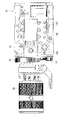
- FIG. 10 shows a cross-sectional configuration in which the front surface portion 12, the body mount 20, and the adapter 30 shown in FIG. 9 are cut in the radial direction through the second lens release button 35C.
- the body mount 20 includes the mounting ring 21, the holding ring 22, and the fastening ring 33 in order from the inner peripheral side.
- the mounting surface 31 of the outer peripheral portion 32 of the adapter 30 is in contact with the first reference plane P1 of the mounting ring 21 of the body mount 20.
- the outer peripheral portion 32 of the adapter 30 is sandwiched and held between the first reference plane P1 of the mounting ring 21 and the claw 22A of the holding ring 22.
- An inner peripheral portion 33 of the adapter 30 enters a mount space MS surrounded by the body mount 20 and the front surface portion 12 of the body 10.
- the optical component 13 is disposed on the front surface portion 12 so as to face the opening of the inner peripheral portion 33 of the adapter 30.
- the optical component 13 is supported by the optical component support member 17.
- the optical component support member 17 is fixed to the chassis member 16 by screws 17A and 17B (not shown in FIG. 10, see FIG. 6).
- the optical component 13 has a distance D13 (in FIG. 2 in FIG. 2) in the optical axis direction Z between the optical component 13 and the imaging surface P11 in order to avoid interference between the optical component 13 and the adapter 30 as the shortening design described above.
- A) is preferably shortened.
- the optical component support member 17 and the chassis member 16 are retracted toward the imaging surface P11 in the optical axis direction Z as the above-described interference avoidance design.
- the retraction amount R12 (see FIG. 3B) at that time is the difference between the first flange back FB1 unique to the body 10 and the second flange back FB of the adapter 30 or the second lens 2B to be mounted. Accordingly, it is preferable that the interference with the adapter 30 be avoided. By doing so, it is possible to secure an extra space on the body 10 side and avoid interference between the adapter 30 that has entered the mount space MS and the front surface portion 12 of the body 10. Specifically, as shown in FIG.
- a space S ⁇ b> 17 is created near the optical component support member 17, and a space S ⁇ b> 16 is created near the chassis member 16.
- the second contact support member 42 ⁇ / b> A is preferably retracted toward the imaging plane P ⁇ b> 11 in the optical axis direction Z as a similar interference avoidance design.
- a space S42 is created in the vicinity of the second contact support member 42A.
- FIG. 11 is an enlarged view of a cross-sectional configuration in the vicinity of the second lens release button 35C shown in FIG.
- the first contact support member 41A has a relief C41 at a position facing the second lens release button 35 in a state where the adapter 30 is mounted on the first reference plane P1.
- the relief C41 is obtained by retracting a portion (a portion in the vicinity of the screw 41C) of the first contact support member 41A that interferes with the second lens release button 35C toward the imaging surface P11 side in the optical axis direction Z.
- the first contact support member 41A can connect the first contact 41 to the first lens 2A in the optical axis direction Z while avoiding interference with the second lens release button 35C. It becomes possible to hold in position.
- the adapter 30 and the second lens 2B can be attached to the body 10 as follows.
- the outer claws 32A of the outer peripheral portion 32 of the adapter 30 are fitted between the claws 22A of the holding ring 22 of the body mount 20.
- the fastening ring 23 is rotated in the tightening direction so that the outer claw 32A of the adapter 30 is sandwiched between the claw 22A of the body mount 20 and the first reference plane P1, and the adapter 30 is moved to the first reference plane of the body mount 20. Attach to P1 and fix.
- the inner peripheral portion 33 is formed between the body mount 20 and the front surface of the body 10 with the outer peripheral portion 32 attached to the first reference plane P1 of the body mount 20. Enter the enclosed mount space MS.
- the front surface portion 12 of the body 10 specifically, the optical component support member 13, the second contact support member 42A, and the chassis member 16 are retracted backward in the optical axis direction Z by the above-described interference avoidance design, Interference with the adapter 30 attached to the first reference plane P1 is avoided.
- the first contact support member 41A has the relief C41, interference with the second lens release button 35C is avoided.
- a claw (not shown) at the rear end of the second lens 2B is fitted between the inner claw 35A of the inner peripheral portion 33 of the adapter 30, and the second lens 2B is rotated.
- the second lens 2B is attached and fixed to the second reference plane P2 of the adapter 30.
- the first reference plane P1 of the body mount 20 has the second reference plane P2, and is shorter than the first flange back FB1 between the second reference plane P2 and the imaging plane P11.
- An adapter 30 having a two-flange back FB2 can be attached. Therefore, it is possible to use the second lens 2 ⁇ / b> B having a second flange back shorter than the first flange back inherent to the body 10 without exchanging the entire body mount 20.
- the front surface portion 12 of the body 10 is configured to avoid interference with the adapter 30 attached to the first reference surface P1.
- the optical component support member 13, the second contact support member 42A, and the chassis member 16 are retracted backward in the optical axis direction Z. Therefore, it is possible to avoid interference with the adapter 30 attached to the first reference plane P1.
- the relief C41 is provided in the first contact support member 41A, it is possible to avoid interference with the second lens release button 35C.
- FIG. 12 represents the structure which looked at the adapter 30 in 2nd Embodiment of this indication from the front front.
- FIG. 12B illustrates a cross-sectional configuration along the line XIIB-XIIB in FIG.
- FIG. 13 illustrates a configuration of the adapter 30 illustrated in FIG. 12 as viewed from the back side.
- the adapter 30 of the present embodiment is different from the adapter 30 of the first embodiment in that a spigot method is adopted as a mounting method of the second lens 2B. Therefore, corresponding constituent elements will be described with the same reference numerals.
- the adapter 30 has the above-described first reference plane P1 between the first reference plane P1 and the imaging plane P11, as in the first embodiment. It can be mounted on the first reference plane P1 of the body mount 20 having the first flange back FB1.
- the adapter 30 has a second flange back FB2 having a second reference surface P2 and shorter than the first flange back FB1 between the second reference surface P2 and the imaging surface P11.
- the second reference surface P2 is a surface on which the second lens 2B (see FIG. 2A) having the second flange back FB2 is mounted.
- the camera 1 can support the second lens 2B having the second flange back FB2 shorter than the first flange back FB1 unique to the body 10 without exchanging the entire body mount 20.
- the adapter 30 fixes the second lens 2B having the second flange back FB2 to the body mount 20 by a spigot method.
- the adapter 30 includes an outer peripheral portion 32, an inner peripheral portion 33, an intermediate portion 34, a fastening portion 36, and a spigot mechanism 37.
- a circular opening 33 ⁇ / b> A is provided on the inner peripheral side of the adapter 30.
- the diameter of the adapter 30 is smaller than the diameter of the body mount 20.
- the outer peripheral portion 32 is a portion that is attached to the first reference surface P ⁇ b> 1 of the body mount 20, and has a mounting surface 31.
- the mounting surface 31 is a surface in contact with the first reference surface P1 in a state where the mounting surface 31 is mounted on the first reference surface P1 of the body mount 20.
- the outer peripheral portion 32 has outer claws 32A for attachment to the body mount 20 at three locations in the circumferential direction.
- the fastening part 36 fastens, fixes, or removes the second lens 2B and the adapter 30 by rotating around the optical axis A.
- the fastening portion 36 is fixed to the front side in the optical axis direction Z of the outer peripheral portion 32 by a screw 36A.
- the fastening portion 36 is provided with a detachable lever 36B.
- the attachment / detachment lever 36B is an operation lever for fastening the second lens 2B to the adapter 30 or removing the second lens 2B from the adapter 30 as shown in FIG.
- the detachable lever 36 ⁇ / b> B is provided obliquely to the upper left in the circumferential direction of the fastening portion 36.
- the fastening portion 36 preferably has an inclined surface 36 ⁇ / b> C at the boundary with the inner peripheral portion 33.
- the inclined surface 36C By having the inclined surface 36C, it is possible to deal with lenses having various shapes.
- the inclined surface 36C is provided, a marginal space is created around the detachable lever 36B, and the user can easily operate the detachable lever 36B.
- the inner peripheral portion 33 is provided concentrically inside the outer peripheral portion 32 and has a second reference plane P2.
- the second reference plane P2 is preferably located on the imaging plane P11 side with respect to the mounting surface 31 in the optical axis direction Z. In this way, the second lens 2B having the second flange back FB2 shorter than the first flange back FB1 unique to the body 10 can be attached to the body mount 20 via the adapter 30. .
- the spigot mechanism 37 is provided behind the inner peripheral portion 33 in the optical axis direction Z, and has inner claws 37A at three locations in the circumferential direction.
- the spigot mechanism 37 is fixed to the fastening portion 36 by a connecting portion 37B, and can be rotated around the optical axis A as the fastening portion 36 rotates.
- the connecting portion 37 ⁇ / b> B is provided in a guide groove 32 ⁇ / b> B cut in a part of the outer peripheral portion 32 in the circumferential direction. Accordingly, the movable range of the connecting portion 37B and the fastening portion 36 is defined by the guide groove 32B.
- the intermediate part 34 is a step part that connects the fastening part 36 and the outer peripheral part 32 and the inner peripheral part 33 in the optical axis direction Z.
- the intermediate part 34 preferably has a fastening part 36 and an inclined surface 34A that connects the outer peripheral part 32 and the inner peripheral part 33.
- FIG. 14 and FIG. 15 show a configuration in which the adapter 30 is mounted on the body mount 20 shown in FIG. 6 as viewed from the front front of the body mount 20.
- FIG. 14 shows a state where the detachable lever 36B is in the initial position PI
- FIG. 15 shows a case where the detachable lever 36B is in the fastening position PT. 14 and 15 also show the fastening ring 23 omitted in FIG.
- the first contact 41 is hidden by the adapter 30, and the second contact 42 is on the inner peripheral side of the adapter 30. It is preferable to be exposed from the opening 33A. Accordingly, the second contact 42 is exposed from the opening 33A opened on the inner peripheral side of the adapter 30 in a state where the adapter 30 is mounted on the first reference plane P1, and the second contact 42 and the second lens 2B can be easily formed. It becomes possible to connect to.
- the adapter 30 by making the first contact 41 hidden by the adapter 30, it is possible to easily recognize that the first lens 2 ⁇ / b> A is not in a state where the first lens 2 ⁇ / b> A can be attached, thereby making it difficult to make a mistake in attaching the lens. Is possible.
- the fastening ring 23 preferably has a notch portion 23B at a part in the circumferential direction, for example, below the body mount 20 when viewed from the front front. It is preferable that the height in the optical axis direction Z of the cutout portion 23B is, for example, the same plane or substantially the same plane as the holding ring 22.
- the fastening ring 23 has a standing wall portion 23C other than the notch portion 23B.
- the standing wall portion 23C preferably has a central angle ⁇ about the optical axis A of 180 ° or more.
- the movable range R36B of the detachable lever 36B of the adapter 30 is preferably provided within the range of the standing wall portion 23C other than the notch portion 23B of the fastening ring 23. As a result, the operation of the detachable lever 36B can be performed without interference with components protruding downward from the lens barrel of the second lens 2B.
- the movable range R36B of the attachment / detachment lever 36B of the adapter 30 is preferably obliquely upward in the circumferential direction of the body mount 20, for example, diagonally upward left or diagonally upward right, when the body mount 20 is viewed from the front front.
- the detachable lever 36 ⁇ / b> B is above in the circumferential direction of the body mount 20, the user is confused as to whether the detachable lever 36 is turned clockwise or counterclockwise.
- the detachable lever 36B is positioned obliquely upward, the user can easily visually and intuitively grasp that the detachable lever 36B is fastened by lowering the detachable lever 36B.
- the detachable lever 36 ⁇ / b> B is often operated by an assistant cameraman who assists the main cameraman standing beside the camera 1. Therefore, by arranging the detachable lever 36B obliquely upward, the assistant photographer can easily operate the detachable lever 36B. Thus, work efficiency is improved.
- the initial position PI of the detachable lever 36B shown in FIG. 14 is obliquely left upward in the circumferential direction of the body mount 20 when the body mount 20 is viewed from the front front, and the detachable lever 36B shown in FIG.
- the fastening position PT is preferably at a position rotated counterclockwise CCW from the initial position PI.
- the initial position PI of the detachable lever 36B is set to be obliquely upward to the right, and the fastening position PT of the detachable lever 36B is a position rotated clockwise from the initial position PI. It is also possible to do.
- FIG. 16 illustrates a cross-sectional configuration in which the front surface portion 12, the body mount 20, and the adapter 30 illustrated in FIG. 14 are cut in the radial direction through the detachable lever 36B.
- FIG. 17 shows an enlarged cross-sectional configuration in the vicinity of the detachable lever 36B shown in FIG.
- the body mount 20 includes the mounting ring 21, the holding ring 22, and the fastening ring 33 in order from the inner peripheral side.
- the mounting surface 31 of the outer peripheral portion 32 of the adapter 30 is in contact with the first reference plane P1 of the mounting ring 21 of the body mount 20.
- An inner peripheral portion 33 of the adapter 30 enters a mount space MS surrounded by the body mount 20 and the front surface portion 12 of the body 10.
- the optical component 13 is disposed on the front surface portion 12 so as to face the opening of the inner peripheral portion 33 of the adapter 30.
- the optical component 13 is supported by the optical component support member 17.
- the optical component support member 17 is fixed to the chassis member 16 by screws 17A and 17B (not shown in FIG. 14, see FIG. 6).
- the optical component 13 has a distance D13 (in FIG. 2 in FIG. 2) in the optical axis direction Z between the optical component 13 and the imaging surface P11 in order to avoid interference between the optical component 13 and the adapter 30 as the above-described shortening design.
- A) is preferably shortened.
- the optical component support member 17, the chassis member 16, and the second contact support member 42A recede toward the imaging plane P11 in the optical axis direction Z as the above-described interference avoidance design.
- the retraction amount R12 (see FIG. 3B) at that time is the difference between the first flange back FB1 unique to the body 10 and the second flange back FB of the adapter 30 or the second lens 2B to be mounted. Accordingly, it is preferable that the interference with the adapter 30 be avoided. By doing so, it is possible to secure an extra space on the body 10 side and avoid interference between the adapter 30 that has entered the mount space MS and the front surface portion 12 of the body 10.
- the adapter 30 and the second lens 2B can be attached to the body 10 as follows.
- the outer claws 32A of the outer peripheral portion 32 of the adapter 30 are fitted between the claws 22A of the holding ring 22 of the body mount 20.
- the fastening ring 23 is rotated in the tightening direction so that the outer claw 32A of the adapter 30 is sandwiched between the claw 22A of the body mount 20 and the first reference plane P1, and the adapter 30 is moved to the first reference plane of the body mount 20. Attach to P1 and fix.
- the inner peripheral portion 33 is formed between the body mount 20 and the front surface of the body 10 with the outer peripheral portion 32 attached to the first reference plane P1 of the body mount 20. Enter the enclosed mount space MS.
- the front surface portion 12 of the body 10, specifically, the optical component support member 13, the chassis member 16, the first contact support member 41A, and the second contact support member 42A are rearward in the optical axis direction Z by the interference avoidance design described above. Therefore, interference with the adapter 30 attached to the first reference plane P1 is avoided.
- a claw (not shown) at the rear end of the second lens 2B is fitted between the inner claw 37A of the spigot mechanism 37 of the adapter 30, and the detachable lever 36B is moved from the initial position PI shown in FIG. 14 to FIG. It is moved to the indicated fastening position PT.
- the second lens 2B is attached and fixed to the second reference plane P2 of the adapter 30.
- the rotation direction in which the fastening ring 23 is tightened in the body mount 20 and the rotation direction in which the fastening portion 36 is rotated in the adapter 30 to disengage the second lens 2B from the second reference plane P2 are the optical axis A. It is preferable that it is reverse rotation centering on. By doing so, when the user turns the fastening ring 23 of the body mount 20 in the direction of loosening, the turning direction is reversely strengthened for the second lens 2B. Therefore, if the user tries to remove the second lens 2B from the adapter 30 and mistakenly turns the fastening ring 23 of the body mount 20 in the clockwise direction CW instead of the detachable lever 36B, nothing will come off.
- the spigot method is adopted as the fastening method between the adapter 30 and the second lens 2B. It becomes possible to fasten to a more firmly. Further, since the body mount 20 also adopts the spigot system, it is possible to reduce the play that may occur when the adapter 30 is used.
- a cinema photographic lens adapter 30C is attached to the body mount 20, and as shown in FIG. 19, a third cinema photographic adapter is attached to the adapter 30C.
- the lens 2C can be attached and used.
- the body 10 may further be equipped with a viewfinder, a recorder, a battery, etc. (all not shown).
- the adapter 30 ⁇ / b> C converts the body mount 20 of the camera 1 into a PL mount that is a cinema industry standard, and has a third contact 43.
- the third contact 43 is disposed upward and to the right in the circumferential direction of the body mount 20 when the body mount 20 is viewed from the front front.
- the adapter 30C and the third lens 2C have a third flange back FB3 (see FIG. 1B) that is longer than the first flange back FB1 unique to the body 10. By using such an adapter 30C, the third lens 2C having the third flange back FB3 longer than the first flange back FB1 can be attached to the body mount 20.
- the camera 1 is mounted on the body mount 20 with the adapter 30 according to the first embodiment or the second embodiment, and further shown in FIG.
- the adapter 30 can be used with the second lens 2B attached thereto.
- the second lens 2B is a still image photographing lens for a mirrorless camera, for example, and has a second flange back FB2 (see FIG. 2A) shorter than the first flange back FB1 unique to the body 10. ing.
- the second lens 2B may be a single-lens reflex lens, or one that can capture both still images and moving images.
- the user of the third lens 2C used in the video industry can easily use the second lens 2B used in the photographic industry. Become. Therefore, it is possible to lower the barrier of classification according to applications such as cinema shooting, broadcasting, and consumer still image shooting, and users can easily obtain new experience opportunities and expand the possibility of video expression. It becomes.
- Modification 1 For example, as shown in FIG. 21, when the body mount 20 is viewed from the front front, the first contact 41 is upward and right in the circumferential direction of the body mount 20, and the second contact 42 is upward in the circumferential direction of the body mount 20. It is also possible to arrange them.
- Modification 2 For example, as shown in FIG. 22, when the body mount 20 is viewed from the front front, the first contact 41 is upward and rightward in the circumferential direction of the body mount 20, and the second contact 42 is in the circumferential direction of the body mount 20. It can also be arranged on the left.
- Modification 4 In addition, for example, as shown in FIG. 24, when the body mount 20 is viewed from the front front, the first contact 41 is leftward in the circumferential direction of the body mount 20, and the second contact 42 is upward in the circumferential direction of the body mount 20. It is also possible to arrange them.
- the configuration of the camera 1 and the adapter 30 has been specifically described. However, not all the components may be provided, and other components may be further provided. Also good.
- the present technology may be configured as follows. (1) A body mount having a first reference surface and having a first flange back between the first reference surface and the imaging surface, the second reference surface having a second reference surface on the first reference surface, A camera capable of mounting an adapter having a second flange back shorter than the first flange back between the imaging surface. (2) The camera according to (1), wherein the second reference surface is located closer to the imaging surface than the first reference surface in the optical axis direction.
- the body mount is provided, and further includes a body incorporating an image sensor,
- the body is A first contact that connects the body and a first lens that is mounted on the first reference surface and has the first flange back;
- a second contact mounted on the second reference surface and having the second flange back and connecting the body;
- the adapter has an opening on the inner peripheral side, The camera according to (3), wherein the second contact is exposed from the opening on an inner peripheral side of the adapter in a state where the adapter is mounted on the first reference surface.
- the body mount is provided on a front portion of the body, The camera according to (3) or (4), wherein the front portion is configured to avoid interference with the adapter attached to the first reference surface.
- the front part is An optical component provided to face the image sensor; An optical component support member for supporting the optical component; The first contact; A first contact support member for supporting the first contact; The second contact; A second contact support member for supporting the second contact;
- the camera according to (5) further comprising: a chassis member that supports the optical component support member, the first contact support member, and the second contact support member.
- the optical component support member, the second contact support member, and the chassis member are retracted to the imaging surface side in the optical axis direction with a retraction amount that can avoid interference with the adapter mounted on the first reference surface.
- the adapter includes a bayonet mechanism that holds the second lens on the second reference surface, and a second lens release button that releases the second lens from the second reference surface,
- the first contact support member has a relief at a position facing the second lens release button in a state where the adapter is mounted on the first reference surface, and the relief is in contact with the second lens release button.
- the body mount has a fastening ring for attaching and detaching the first lens or the adapter to the first reference surface by a spigot method.
- the fastening ring has a notch portion provided in a part of the circumferential direction, and a standing wall portion other than the notch portion,
- the adapter includes a fastening portion rotatable around an optical axis, a detachable lever provided in the fastening portion, and a spigot mechanism rotatable around the optical axis as the fastening portion rotates.
- the body mount has a fastening ring for attaching and detaching the first lens or the adapter to the first reference surface by a spigot method.
- the fastening ring has a notch portion provided in a part of the circumferential direction, and a standing wall portion other than the notch portion,
- the camera according to any one of (3) to (7), wherein a movable range of the detachable lever is within a range of the standing wall portion of the fastening ring.
- a rotation direction in which the fastening ring is loosened in the body mount and a rotation direction in which the second lens is detached from the second reference surface in the adapter are opposite to each other about the optical axis (11) Or the camera according to any one of (13).
- the first contact is disposed upward and rightward in the circumferential direction of the body mount, and the second contact is disposed upward in the circumferential direction of the body mount.
- the first contact point is arranged on the upper side and the right side in the circumferential direction of the body mount, and the second contact point is downward or diagonally left downward in the circumferential direction of the body mount.
- the camera according to any one of (3) to (15), wherein the camera is disposed.
- the first contact is disposed on the left in the circumferential direction of the body mount, and the second contact is disposed on the lower side in the circumferential direction of the body mount.
- the first contact is disposed on the left in the circumferential direction of the body mount, and the second contact is disposed on the upper side in the circumferential direction of the body mount.
- the camera according to any one of (15).
- the first reference surface of the body mount having a first reference surface and having a first flange back between the first reference surface and the imaging surface can be mounted on the first reference surface and has a second reference surface.
- the adapter is An outer peripheral portion mounted on the first reference surface of the body mount; A mount that is concentrically provided inside the outer peripheral portion, has the second reference surface, and is surrounded by the body mount and the front surface of the body with the outer peripheral portion being attached to the first reference surface
- the adapter according to (20) or (21) further including an inner peripheral portion that enters the space.
Landscapes
- Physics & Mathematics (AREA)
- General Physics & Mathematics (AREA)
- Engineering & Computer Science (AREA)
- Multimedia (AREA)
- Signal Processing (AREA)
- Structure And Mechanism Of Cameras (AREA)
- Studio Devices (AREA)
- Accessories Of Cameras (AREA)
- Lens Barrels (AREA)
Abstract
Description
1.概略説明
2.第1の実施の形態(アダプタがバヨネット方式を採用している例)
3.第2の実施の形態(アダプタがスピゴット方式を採用している例)
4.第1適用例(本開示の一実施の形態のボディに、シネマ撮影レンズ用のアダプタを介して、シネマ撮影レンズを装着する例)
5.第2適用例(本開示の一実施の形態のボディに、本開示の一実施の形態のアダプタを介して、第1フランジバックよりも短い第2フランジバックをもつレンズを装着する例)
6.変形例1(ボディマウントを前方正面から見て、第1接点が上方および右方、第2接点が上方に配置されている例)
7.変形例2(ボディマウントを前方正面から見て、第1接点が上方および右方、第2接点が左方に配置されている例)
8.変形例3(ボディマウントを前方正面から見て、第1接点が上方および右方、第2接点が左斜め下方に配置されている例)
9.変形例4(ボディマウントを前方正面から見て、第1接点が左方、第2接点が上方に配置されている例)
まず、個々の具体的な実施の形態の説明に先立ち、図1ないし図3を参照して、本開示の一実施の形態のカメラおよびアダプタの概略を説明する。
図4は、本開示の第1の実施の形態に係るカメラ1のボディ10を右側面側から見た外観を表したものである。図5は、図4に示したボディ10を前方正面から見た外観を表したものである。このカメラ1は、例えばシネマ撮影用カメラであり、ボディ10の光軸方向Zにおける最前部に、ボディマウント20を有している。ボディ10は、外装部材14を有し、この外装部材14に撮像素子11(図4には図示せず、図2参照。)が内蔵されている。外装部材14の各面には、録画スタート釦14A、メニュー選択釦14B、サイドパネル14Cのほか、各種の操作釦や調整釦、ビューファインダー等のアクセサリー装着部、外部メモリ収納部、USB接続部、バッテリー接続部などが適宜設けられている。
図12の(A)は、本開示の第2の実施の形態におけるアダプタ30を前方正面から見た構成を表したものである。図12の(B)は、図12の(A)のXIIB-XIIB線における断面構成を表したものである。図13は、図12に示したアダプタ30を背面側から見た構成を表したものである。本実施の形態のアダプタ30は、第2レンズ2Bの装着方法としてスピゴット方式を採用していることにおいて、上記第1の実施の形態のアダプタ30とは異なるものである。よって、対応する構成要素については同一の符号を付して説明する。
以下、このカメラ1の適用例について説明する。
このカメラ1は、例えば図18に示したように、ボディマウント20に、シネマ撮影レンズ用のアダプタ30Cを装着し、更に図19に示したように、このアダプタ30Cに、シネマ撮影用の第3レンズ2Cを装着して使用することが可能である。ボディ10には、ビューファインダ、レコーダー、バッテリー等(いずれも図示せず)を更に装着してもよい。
あるいは、このカメラ1は、図9または図15に示したように、ボディマウント20に、第1の実施の形態または第2の実施の形態に係るアダプタ30を装着し、更に図20に示したように、このアダプタ30に、第2レンズ2Bを装着して使用することが可能である。第2レンズ2Bは、例えばミラーレスカメラ用の静止画撮影レンズであり、ボディ10に固有の第1フランジバックFB1よりも短い第2フランジバックFB2(図2の(A)参照。)を有している。なお、第2レンズ2Bは、一眼レフ用のもの、静止画および動画の両方を撮影可能なものでもよい。このように本開示の一実施の形態のアダプタ30を用いることにより、映像業界で使用されてきた第3レンズ2Cのユーザが、写真業界で使用されてきた第2レンズ2Bを気軽に使用可能となる。従って、シネマ撮影用、放送用、コンシューマ向け静止画撮影用などの用途による分類の垣根を低くし、ユーザが容易に新しい体験機会を手に入れて、映像表現の可能性を拡大することが可能となる。
なお、上記実施の形態では、ボディマウント20を前方正面から見て、第1接点41はボディマウント20の周方向において左方、第2接点42はボディマウント20の周方向において下方に設けられている場合について説明した。しかしながら、第1接点41および第2接点42の配置は、上記実施の形態の例に限られず、以下の変形例1~4のように様々に変更可能である。なお、第1接点41および第2接点42の配置の変形例は、以下の変形例1~4に限られないことはいうまでもない。
例えば、図21に示したように、ボディマウント20を前方正面から見て、第1接点41がボディマウント20の周方向において上方および右方、第2接点42がボディマウント20の周方向において上方に配置されていることも可能である。
また、例えば図22に示したように、ボディマウント20を前方正面から見て、第1接点41がボディマウント20の周方向において上方および右方、第2接点42がボディマウント20の周方向において左方に配置されていることも可能である。
更に、例えば図23に示したように、ボディマウント20を前方正面から見て、第1接点41がボディマウント20の周方向において上方および右方、第2接点42がボディマウント20の周方向において左斜め下方に配置されていることも可能である。
加えて、例えば図24に示したように、ボディマウント20を前方正面から見て、第1接点41がボディマウント20の周方向において左方、第2接点42がボディマウント20の周方向において上方に配置されていることも可能である。
(1)
第1基準面を有し前記第1基準面と撮像面との間に第1フランジバックをもつボディマウントを備え、前記第1基準面に、第2基準面を有し前記第2基準面と前記撮像面との間に前記第1フランジバックよりも短い第2フランジバックをもつアダプタを装着可能である
カメラ。
(2)
前記第2基準面は、光軸方向において前記第1基準面よりも前記撮像面側に位置する
前記(1)記載のカメラ。
(3)
前記ボディマウントが設けられると共に撮像素子を内蔵するボディを更に備え、
前記ボディは、
前記第1基準面に装着され前記第1フランジバックをもつ第1レンズと前記ボディとを接続する第1接点と、
前記第2基準面に装着され前記第2フランジバックをもつ第2レンズと前記ボディとを接続する第2接点と
を有し、
前記第2接点は、前記ボディマウントの径方向において前記第1接点よりも内周側に位置する
前記(1)または(2)記載のカメラ。
(4)
前記アダプタは内周側に開口を有し、
前記第2接点は、前記第1基準面に前記アダプタが装着された状態で前記アダプタの内周側の前記開口から露出している
前記(3)記載のカメラ。
(5)
前記ボディマウントは、前記ボディの前面部に設けられ、
前記前面部は、前記第1基準面に装着される前記アダプタとの干渉を回避可能に構成されている
前記(3)または(4)記載のカメラ。
(6)
前記前面部は、
前記撮像素子に対向して設けられた光学部品と、
前記光学部品を支持する光学部品支持部材と、
前記第1接点と、
前記第1接点を支持する第1接点支持部材と、
前記第2接点と、
前記第2接点を支持する第2接点支持部材と、
前記光学部品支持部材、前記第1接点支持部材および前記第2接点支持部材を支持するシャーシ部材と
を有する前記(5)記載のカメラ。
(7)
前記光学部品支持部材、前記第2接点支持部材および前記シャーシ部材は、前記第1基準面に装着される前記アダプタとの干渉を回避可能な後退量で、光軸方向において前記撮像面側に後退している
前記(6)記載のカメラ。
(8)
前記アダプタは、前記第2基準面に前記第2レンズを保持するバヨネット機構と、前記第2基準面から前記第2レンズを離脱させる第2レンズ離脱釦とを有し、
前記第1接点支持部材は、前記第1基準面に前記アダプタが装着された状態で前記第2レンズ離脱釦に対向する位置に逃げを有し、前記逃げは、前記第2レンズ離脱釦との干渉を回避可能な後退量で、光軸方向において前記撮像面側に後退している
前記(6)または(7)記載のカメラ。
(9)
前記第2レンズ離脱釦は、光軸方向において前記外周部の前面よりも前記第2レンズ側へ突出している
前記(8)記載のカメラ。
(10)
前記ボディマウントは、スピゴット方式により前記第1基準面に前記第1レンズまたは前記アダプタを着脱させる締結環を有し、
前記締結環は、周方向の一部に設けられた切欠き部分と、前記切欠き部分以外の立ち壁部分とを有し、
前記第2レンズ離脱釦は、前記切欠き部分の範囲内に設けられている
前記(8)または(9)記載のカメラ。
(11)
前記アダプタは、光軸の周りに回動可能な締結部と、前記締結部に設けられた着脱レバーと、前記締結部の回動に伴って光軸の周りに回動可能なスピゴット機構とを有し、
前記ボディマウントは、スピゴット方式により前記第1基準面に前記第1レンズまたは前記アダプタを着脱させる締結環を有し、
前記締結環は、周方向の一部に設けられた切欠き部分と、前記切欠き部分以外の立ち壁部分とを有し、
前記着脱レバーの可動範囲は、前記締結環の前記立ち壁部分の範囲内にある
前記(3)ないし(7)のいずれかに記載のカメラ。
(12)
前記着脱レバーの可動範囲は、前記ボディマウントを前方正面から見て前記ボディマウントの周方向における左斜め上方または右斜め上方にある
前記(11)記載のカメラ。
(13)
前記着脱レバーの初期位置は、前記ボディマウントを前方正面から見て前記ボディマウントの周方向における左斜め上方にあり、
前記着脱レバーの締結位置は、前記初期位置から反時計回りに回動した位置にある
前記(12)記載のカメラ。
(14)
前記ボディマウントにおいて前記締結環を緩める回動方向と、前記アダプタにおいて前記第2基準面から前記第2レンズを離脱させる回動方向とが、光軸を中心にして逆回りである
前記(11)ないし(13)のいずれかに記載のカメラ。
(15)
前記第1接点および前記第2接点は、前記ボディマウントを前方正面から見て前記ボディマウントの周方向において異なる位置に配置されている
前記(3)ないし(14)のいずれかに記載のカメラ。
(16)
前記ボディマウントを前方正面から見て、前記第1接点は前記ボディマウントの周方向において上方および右方に配置されており、前記第2接点は前記ボディマウントの周方向において上方に配置されている
前記(3)ないし(15)のいずれかに記載のカメラ。
(17)
前記ボディマウントを前方正面から見て、前記第1接点は前記ボディマウントの周方向において上方および右方に配置されており、前記第2接点は前記ボディマウントの周方向において下方または左斜め下方に配置されている
前記(3)ないし(15)のいずれかに記載のカメラ。
(18)
前記ボディマウントを前方正面から見て、前記第1接点は前記ボディマウントの周方向において左方に配置されており、前記第2接点は前記ボディマウントの周方向において下方に配置されている
前記(3)ないし(15)のいずれかに記載のカメラ。
(19)
前記ボディマウントを前方正面から見て、前記第1接点は前記ボディマウントの周方向において左方に配置されており、前記第2接点は前記ボディマウントの周方向において上方に配置されている
前記(3)ないし(15)のいずれかに記載のカメラ。
(20)
第1基準面を有し前記第1基準面と撮像面との間に第1フランジバックをもつボディマウントの前記第1基準面に装着可能であると共に、第2基準面を有し前記第2基準面と前記撮像面との間に前記第1フランジバックよりも短い第2フランジバックを有する
アダプタ。
(21)
前記第2基準面は、光軸方向において前記第1基準面よりも前記撮像面側に位置する
前記(20)記載のアダプタ。
(22)
前記アダプタは、
前記ボディマウントの前記第1基準面に装着される外周部と、
前記外周部の内側に同心円状に設けられると共に前記第2基準面を有し、前記外周部が前記第1基準面に装着された状態で前記ボディマウントと前記ボディの前面とにより囲まれたマウント空間内に入り込む内周部と
を有する前記(20)または(21)記載のアダプタ。
(23)
前記外周部と前記内周部との間に中間部を有する
前記(22)記載のアダプタ。
(24)
前記中間部は、前記外周部と前記内周部とをつなぐ傾斜面を有する
前記(23)記載のアダプタ。
Claims (20)
- 第1基準面を有し前記第1基準面と撮像面との間に第1フランジバックをもつボディマウントを備え、前記第1基準面に、第2基準面を有し前記第2基準面と前記撮像面との間に前記第1フランジバックよりも短い第2フランジバックをもつアダプタを装着可能である
カメラ。 - 前記第2基準面は、光軸方向において前記第1基準面よりも前記撮像面側に位置する
請求項1記載のカメラ。 - 前記ボディマウントが設けられると共に撮像素子を内蔵するボディを更に備え、
前記ボディは、
前記第1基準面に装着され前記第1フランジバックをもつ第1レンズと前記ボディとを接続する第1接点と、
前記第2基準面に装着され前記第2フランジバックをもつ第2レンズと前記ボディとを接続する第2接点と
を有し、
前記第2接点は、前記ボディマウントの径方向において前記第1接点よりも内周側に位置する
請求項1記載のカメラ。 - 前記アダプタは内周側に開口を有し、
前記第2接点は、前記第1基準面に前記アダプタが装着された状態で前記アダプタの内周側の前記開口から露出している
請求項3記載のカメラ。 - 前記ボディマウントは、前記ボディの前面部に設けられ、
前記前面部は、前記第1基準面に装着される前記アダプタとの干渉を回避可能に構成されている
請求項3記載のカメラ。 - 前記前面部は、
前記撮像素子に対向して設けられた光学部品と、
前記光学部品を支持する光学部品支持部材と、
前記第1接点と、
前記第1接点を支持する第1接点支持部材と、
前記第2接点と、
前記第2接点を支持する第2接点支持部材と、
前記光学部品支持部材、前記第1接点支持部材および前記第2接点支持部材を支持するシャーシ部材と
を有する請求項5記載のカメラ。 - 前記光学部品支持部材、前記第2接点支持部材および前記シャーシ部材は、前記第1基準面に装着される前記アダプタとの干渉を回避可能な後退量で、光軸方向において前記撮像面側に後退している
請求項6記載のカメラ。 - 前記アダプタは、前記第2基準面に前記第2レンズを保持するバヨネット機構と、前記第2基準面から前記第2レンズを離脱させる第2レンズ離脱釦とを有し、
前記第1接点支持部材は、前記第1基準面に前記アダプタが装着された状態で前記第2レンズ離脱釦に対向する位置に逃げを有し、前記逃げは、前記第2レンズ離脱釦との干渉を回避可能な後退量で、光軸方向において前記撮像面側に後退している
請求項6記載のカメラ。 - 前記第2レンズ離脱釦は、光軸方向において前記外周部の前面よりも前記第2レンズ側へ突出している
請求項8記載のカメラ。 - 前記ボディマウントは、スピゴット方式により前記第1基準面に前記第1レンズまたは前記アダプタを着脱させる締結環を有し、
前記締結環は、周方向の一部に設けられた切欠き部分と、前記切欠き部分以外の立ち壁部分とを有し、
前記第2レンズ離脱釦は、前記切欠き部分の範囲内に設けられている
請求項8記載のカメラ。 - 前記アダプタは、光軸の周りに回動可能な締結部と、前記締結部に設けられた着脱レバーと、前記締結部の回動に伴って光軸の周りに回動可能なスピゴット機構とを有し、
前記ボディマウントは、スピゴット方式により前記第1基準面に前記第1レンズまたは前記アダプタを着脱させる締結環を有し、
前記締結環は、周方向の一部に設けられた切欠き部分と、前記切欠き部分以外の立ち壁部分とを有し、
前記着脱レバーの可動範囲は、前記締結環の前記立ち壁部分の範囲内にある
請求項3記載のカメラ。 - 前記着脱レバーの可動範囲は、前記ボディマウントを前方正面から見て前記ボディマウントの周方向における左斜め上方または右斜め上方にある
請求項11記載のカメラ。 - 前記着脱レバーの初期位置は、前記ボディマウントを前方正面から見て前記ボディマウントの周方向における左斜め上方にあり、
前記着脱レバーの締結位置は、前記初期位置から反時計回りに回動した位置にある
請求項12記載のカメラ。 - 前記ボディマウントにおいて前記締結環を緩める回動方向と、前記アダプタにおいて前記第2基準面から前記第2レンズを離脱させる回動方向とが、光軸を中心にして逆回りである
請求項11記載のカメラ。 - 前記第1接点および前記第2接点は、前記ボディマウントを前方正面から見て前記ボディマウントの周方向において異なる位置に配置されている
請求項3記載のカメラ。 - 前記ボディマウントを前方正面から見て、前記第1接点は前記ボディマウントの周方向において上方および右方に配置されており、前記第2接点は前記ボディマウントの周方向において上方に配置されている
請求項3記載のカメラ。 - 前記ボディマウントを前方正面から見て、前記第1接点は前記ボディマウントの周方向において上方および右方に配置されており、前記第2接点は前記ボディマウントの周方向において下方または左斜め下方に配置されている
請求項3記載のカメラ。 - 前記ボディマウントを前方正面から見て、前記第1接点は前記ボディマウントの周方向において左方に配置されており、前記第2接点は前記ボディマウントの周方向において下方に配置されている
請求項3記載のカメラ。 - 前記ボディマウントを前方正面から見て、前記第1接点は前記ボディマウントの周方向において左方に配置されており、前記第2接点は前記ボディマウントの周方向において上方に配置されている
請求項3記載のカメラ。 - 第1基準面を有し前記第1基準面と撮像面との間に第1フランジバックをもつボディマウントの前記第1基準面に装着可能であると共に、第2基準面を有し前記第2基準面と前記撮像面との間に前記第1フランジバックよりも短い第2フランジバックを有する
アダプタ。
Priority Applications (4)
| Application Number | Priority Date | Filing Date | Title |
|---|---|---|---|
| EP14881087.2A EP3101473B1 (en) | 2014-01-30 | 2014-11-28 | Camera and adapter |
| US15/108,341 US10051164B2 (en) | 2014-01-30 | 2014-11-28 | Camera and adapter |
| JP2015559747A JP6575359B2 (ja) | 2014-01-30 | 2014-11-28 | カメラおよびアダプタ |
| CN201480072635.0A CN105900009B (zh) | 2014-01-30 | 2014-11-28 | 相机和适配器 |
Applications Claiming Priority (2)
| Application Number | Priority Date | Filing Date | Title |
|---|---|---|---|
| JP2014015452 | 2014-01-30 | ||
| JP2014-015452 | 2014-01-30 |
Publications (1)
| Publication Number | Publication Date |
|---|---|
| WO2015114933A1 true WO2015114933A1 (ja) | 2015-08-06 |
Family
ID=53756527
Family Applications (1)
| Application Number | Title | Priority Date | Filing Date |
|---|---|---|---|
| PCT/JP2014/081521 Ceased WO2015114933A1 (ja) | 2014-01-30 | 2014-11-28 | カメラおよびアダプタ |
Country Status (5)
| Country | Link |
|---|---|
| US (1) | US10051164B2 (ja) |
| EP (1) | EP3101473B1 (ja) |
| JP (1) | JP6575359B2 (ja) |
| CN (1) | CN105900009B (ja) |
| WO (1) | WO2015114933A1 (ja) |
Families Citing this family (4)
| Publication number | Priority date | Publication date | Assignee | Title |
|---|---|---|---|---|
| DE102016121646B3 (de) * | 2016-11-11 | 2018-04-26 | Jos. Schneider Optische Werke Gmbh | Adapter zum Verschwenken eines Objektivs |
| CN116418899A (zh) * | 2021-12-29 | 2023-07-11 | 北京小米移动软件有限公司 | 转接件及移动设备 |
| US12228986B1 (en) | 2024-01-31 | 2025-02-18 | Core SWX, LLC | Device, system, and method for providing power from a USB-C PD connection |
| US12228985B1 (en) * | 2024-01-31 | 2025-02-18 | Core SWX, LLC | Device, system, and method for providing power from a USB-C PD connection |
Citations (6)
| Publication number | Priority date | Publication date | Assignee | Title |
|---|---|---|---|---|
| JPH07295053A (ja) * | 1994-04-26 | 1995-11-10 | Canon Inc | ねじ込みマウントレンズ |
| JP2007058123A (ja) | 2005-08-26 | 2007-03-08 | Olympus Imaging Corp | デジタルカメラシステムおよび中間アダプタ |
| JP2008118199A (ja) * | 2006-10-31 | 2008-05-22 | Nikon Corp | カメラボディ、アダプタ、レンズ鏡筒、カメラシステム、rfid、カメラシステムの動作方法 |
| JP2010160176A (ja) * | 2009-01-06 | 2010-07-22 | Panasonic Corp | カメラシステムのマウントアダプター |
| JP2010286733A (ja) * | 2009-06-12 | 2010-12-24 | Nippon Seimitsu Sokki Kk | 露光条件切替ユニットおよびカメラユニット |
| JP2014015452A (ja) | 2012-06-15 | 2014-01-30 | Taisho Pharmaceutical Co Ltd | ピラゾール誘導体を含有する医薬 |
Family Cites Families (9)
| Publication number | Priority date | Publication date | Assignee | Title |
|---|---|---|---|---|
| US5734935A (en) * | 1995-10-13 | 1998-03-31 | Nikon Corporation | Camera system and intermediate adapter |
| JP3210586B2 (ja) * | 1996-01-08 | 2001-09-17 | 株式会社ニコン | カメラシステム及び中間アダプタ |
| WO2008099605A1 (ja) * | 2007-02-15 | 2008-08-21 | Panasonic Corporation | 撮像装置およびカメラ本体 |
| JP4829380B2 (ja) * | 2008-09-11 | 2011-12-07 | パナソニック株式会社 | 撮像装置 |
| GB2458781B (en) * | 2009-03-26 | 2012-12-12 | Mark Bell | Camera body |
| JP5100722B2 (ja) * | 2009-09-02 | 2012-12-19 | キヤノン株式会社 | 変換アダプタ装置及び交換レンズシステム |
| US8714844B2 (en) * | 2011-09-20 | 2014-05-06 | Nikon Corporation | Intermediate adapter, camera accessory, and exchangeable lens |
| JP3177509U (ja) * | 2012-03-16 | 2012-08-09 | 学校法人西沢学園 | マウントアダプタ |
| US9307128B2 (en) * | 2012-06-26 | 2016-04-05 | Alex Ning | Lens mount |
-
2014
- 2014-11-28 JP JP2015559747A patent/JP6575359B2/ja active Active
- 2014-11-28 WO PCT/JP2014/081521 patent/WO2015114933A1/ja not_active Ceased
- 2014-11-28 US US15/108,341 patent/US10051164B2/en active Active
- 2014-11-28 CN CN201480072635.0A patent/CN105900009B/zh active Active
- 2014-11-28 EP EP14881087.2A patent/EP3101473B1/en not_active Not-in-force
Patent Citations (6)
| Publication number | Priority date | Publication date | Assignee | Title |
|---|---|---|---|---|
| JPH07295053A (ja) * | 1994-04-26 | 1995-11-10 | Canon Inc | ねじ込みマウントレンズ |
| JP2007058123A (ja) | 2005-08-26 | 2007-03-08 | Olympus Imaging Corp | デジタルカメラシステムおよび中間アダプタ |
| JP2008118199A (ja) * | 2006-10-31 | 2008-05-22 | Nikon Corp | カメラボディ、アダプタ、レンズ鏡筒、カメラシステム、rfid、カメラシステムの動作方法 |
| JP2010160176A (ja) * | 2009-01-06 | 2010-07-22 | Panasonic Corp | カメラシステムのマウントアダプター |
| JP2010286733A (ja) * | 2009-06-12 | 2010-12-24 | Nippon Seimitsu Sokki Kk | 露光条件切替ユニットおよびカメラユニット |
| JP2014015452A (ja) | 2012-06-15 | 2014-01-30 | Taisho Pharmaceutical Co Ltd | ピラゾール誘導体を含有する医薬 |
Non-Patent Citations (1)
| Title |
|---|
| See also references of EP3101473A4 |
Also Published As
| Publication number | Publication date |
|---|---|
| US10051164B2 (en) | 2018-08-14 |
| US20160330353A1 (en) | 2016-11-10 |
| CN105900009A (zh) | 2016-08-24 |
| CN105900009B (zh) | 2019-01-01 |
| EP3101473B1 (en) | 2019-11-20 |
| JP6575359B2 (ja) | 2019-09-18 |
| EP3101473A1 (en) | 2016-12-07 |
| EP3101473A4 (en) | 2017-08-30 |
| JPWO2015114933A1 (ja) | 2017-03-23 |
Similar Documents
| Publication | Publication Date | Title |
|---|---|---|
| JP6459984B2 (ja) | カメラおよびアダプタ | |
| JP2015141382A (ja) | 撮像装置および撮像システム | |
| JP6760292B2 (ja) | 撮像装置とカメラグリップおよび撮像システム | |
| US20120008043A1 (en) | Imaging apparatus | |
| JP6575359B2 (ja) | カメラおよびアダプタ | |
| JP2010117571A (ja) | カメラ、カメラ用アクセサリ | |
| JP4798178B2 (ja) | レンズ鏡筒及び撮像装置 | |
| US9823550B2 (en) | Camera apparatus and mount adapter | |
| US9429819B2 (en) | Camera and optical unit | |
| JP2008175897A (ja) | 光学レンズ検出構造、着脱構造及びこれらを備えた撮影装置 | |
| JP2013083691A (ja) | 撮像装置 | |
| JP2009300926A (ja) | カメラアクセサリ及びカメラシステム | |
| JP2014098822A (ja) | レンズ鏡筒およびこれを備えた光学機器 | |
| JP5448990B2 (ja) | レンズ装置のアクセサリ着脱機構 | |
| JP5948975B2 (ja) | レンズキャップ | |
| JP5453811B2 (ja) | カメラシステムのマウントアダプター | |
| JP2025007719A (ja) | レンズフード及びカメラ及びレンズフードの製造方法 | |
| JP2009300927A (ja) | カメラアクセサリ及びカメラシステム | |
| JP2009145580A (ja) | 撮像装置 | |
| JP2023102950A (ja) | レンズカバー | |
| JP2008281767A (ja) | 撮像装置 | |
| JP2007133237A (ja) | 撮像装置 | |
| JP2005156765A (ja) | レンズアダプタ | |
| KR20100096498A (ko) | 디지털 영상 촬영 장치 | |
| JP2006243385A (ja) | カメラ |
Legal Events
| Date | Code | Title | Description |
|---|---|---|---|
| 121 | Ep: the epo has been informed by wipo that ep was designated in this application |
Ref document number: 14881087 Country of ref document: EP Kind code of ref document: A1 |
|
| ENP | Entry into the national phase |
Ref document number: 2015559747 Country of ref document: JP Kind code of ref document: A |
|
| REEP | Request for entry into the european phase |
Ref document number: 2014881087 Country of ref document: EP |
|
| WWE | Wipo information: entry into national phase |
Ref document number: 2014881087 Country of ref document: EP |
|
| WWE | Wipo information: entry into national phase |
Ref document number: 15108341 Country of ref document: US |
|
| NENP | Non-entry into the national phase |
Ref country code: DE |