WO2015114988A1 - ワイパブレード - Google Patents
ワイパブレード Download PDFInfo
- Publication number
- WO2015114988A1 WO2015114988A1 PCT/JP2014/083621 JP2014083621W WO2015114988A1 WO 2015114988 A1 WO2015114988 A1 WO 2015114988A1 JP 2014083621 W JP2014083621 W JP 2014083621W WO 2015114988 A1 WO2015114988 A1 WO 2015114988A1
- Authority
- WO
- WIPO (PCT)
- Prior art keywords
- blade
- blade rubber
- washer
- wiper blade
- longitudinal direction
- Prior art date
- Legal status (The legal status is an assumption and is not a legal conclusion. Google has not performed a legal analysis and makes no representation as to the accuracy of the status listed.)
- Ceased
Links
Images





Classifications
-
- B—PERFORMING OPERATIONS; TRANSPORTING
- B60—VEHICLES IN GENERAL
- B60S—SERVICING, CLEANING, REPAIRING, SUPPORTING, LIFTING, OR MANOEUVRING OF VEHICLES, NOT OTHERWISE PROVIDED FOR
- B60S1/00—Cleaning of vehicles
- B60S1/02—Cleaning windscreens, windows or optical devices
- B60S1/46—Cleaning windscreens, windows or optical devices using liquid; Windscreen washers
- B60S1/48—Liquid supply therefor
- B60S1/52—Arrangement of nozzles; Liquid spreading means
- B60S1/522—Arrangement of nozzles; Liquid spreading means moving liquid spreading means, e.g. arranged in wiper arms
- B60S1/524—Arrangement of nozzles; Liquid spreading means moving liquid spreading means, e.g. arranged in wiper arms arranged in wiper blades
-
- B—PERFORMING OPERATIONS; TRANSPORTING
- B60—VEHICLES IN GENERAL
- B60S—SERVICING, CLEANING, REPAIRING, SUPPORTING, LIFTING, OR MANOEUVRING OF VEHICLES, NOT OTHERWISE PROVIDED FOR
- B60S1/00—Cleaning of vehicles
- B60S1/02—Cleaning windscreens, windows or optical devices
- B60S1/04—Wipers or the like, e.g. scrapers
- B60S1/32—Wipers or the like, e.g. scrapers characterised by constructional features of wiper blade arms or blades
- B60S1/38—Wiper blades
- B60S1/3848—Flat-type wiper blade, i.e. without harness
- B60S1/3849—Connectors therefor; Connection to wiper arm; Attached to blade
- B60S1/3851—Mounting of connector to blade assembly
- B60S1/3856—Gripping the blade
-
- B—PERFORMING OPERATIONS; TRANSPORTING
- B60—VEHICLES IN GENERAL
- B60S—SERVICING, CLEANING, REPAIRING, SUPPORTING, LIFTING, OR MANOEUVRING OF VEHICLES, NOT OTHERWISE PROVIDED FOR
- B60S1/00—Cleaning of vehicles
- B60S1/02—Cleaning windscreens, windows or optical devices
- B60S1/04—Wipers or the like, e.g. scrapers
- B60S1/32—Wipers or the like, e.g. scrapers characterised by constructional features of wiper blade arms or blades
- B60S1/38—Wiper blades
- B60S1/3848—Flat-type wiper blade, i.e. without harness
- B60S1/3849—Connectors therefor; Connection to wiper arm; Attached to blade
- B60S1/3862—Transport of liquid there through
-
- B—PERFORMING OPERATIONS; TRANSPORTING
- B60—VEHICLES IN GENERAL
- B60S—SERVICING, CLEANING, REPAIRING, SUPPORTING, LIFTING, OR MANOEUVRING OF VEHICLES, NOT OTHERWISE PROVIDED FOR
- B60S1/00—Cleaning of vehicles
- B60S1/02—Cleaning windscreens, windows or optical devices
- B60S1/04—Wipers or the like, e.g. scrapers
- B60S1/32—Wipers or the like, e.g. scrapers characterised by constructional features of wiper blade arms or blades
- B60S1/38—Wiper blades
- B60S1/3848—Flat-type wiper blade, i.e. without harness
- B60S1/3874—Flat-type wiper blade, i.e. without harness with a reinforcing vertebra
- B60S1/3875—Flat-type wiper blade, i.e. without harness with a reinforcing vertebra rectangular section
- B60S1/3881—Flat-type wiper blade, i.e. without harness with a reinforcing vertebra rectangular section in additional element, e.g. spoiler
-
- B—PERFORMING OPERATIONS; TRANSPORTING
- B60—VEHICLES IN GENERAL
- B60S—SERVICING, CLEANING, REPAIRING, SUPPORTING, LIFTING, OR MANOEUVRING OF VEHICLES, NOT OTHERWISE PROVIDED FOR
- B60S1/00—Cleaning of vehicles
- B60S1/02—Cleaning windscreens, windows or optical devices
- B60S1/04—Wipers or the like, e.g. scrapers
- B60S1/32—Wipers or the like, e.g. scrapers characterised by constructional features of wiper blade arms or blades
- B60S1/38—Wiper blades
- B60S1/3848—Flat-type wiper blade, i.e. without harness
- B60S1/3886—End caps
-
- B—PERFORMING OPERATIONS; TRANSPORTING
- B60—VEHICLES IN GENERAL
- B60S—SERVICING, CLEANING, REPAIRING, SUPPORTING, LIFTING, OR MANOEUVRING OF VEHICLES, NOT OTHERWISE PROVIDED FOR
- B60S1/00—Cleaning of vehicles
- B60S1/02—Cleaning windscreens, windows or optical devices
- B60S1/04—Wipers or the like, e.g. scrapers
- B60S1/32—Wipers or the like, e.g. scrapers characterised by constructional features of wiper blade arms or blades
- B60S1/40—Connections between blades and arms
- B60S1/4006—Connections between blades and arms for arms provided with a hook-shaped end
Definitions
- the present invention relates to a wiper blade that is mounted on a wiper arm provided in a vehicle and performs a reciprocating wiping operation on a windshield.
- a vehicle such as an automobile is equipped with a wiper device that secures a driver's view.
- the wiper device includes a wiper arm that is swingably driven by an electric motor, and a wiper blade that is attached to the wiper arm.
- the wiper blade includes a holder member attached to the tip portion of the wiper arm and a blade rubber held by the holder member.
- the wiper blade is reciprocally wiped while spraying the washer liquid onto the windshield.
- the washer liquid is sprayed onto the windshield from a nozzle installed in a vehicle bonnet or the like.
- the spray position of the washer fluid is obstructed by the driver's eyes, and the distance between the nozzle and the windshield is long. Since a relatively large amount of washer liquid is used, there are disadvantages such as the frequency of replenishment of the washer liquid to the washer tank is increased.
- a wiper blade as shown in Patent Document 1 has been developed.
- the wiper blade described in Patent Document 1 includes a flow path (long path) through which the washer liquid flows along the longitudinal direction of the wiper blade, and is directed toward the windshield from a plurality of holes formed in the flow path.
- the washer liquid is sprayed to wet the vicinity of the blade rubber.
- the washer liquid flowing through the flow path is supplied from a central connecting portion attached to the wiper blade.
- the flow path having a plurality of holes is similarly provided on the forward path side and the return path side of the wiper blade and over the entire longitudinal direction of the wiper blade. Is provided. Accordingly, since approximately the same amount of washer liquid is ejected on the forward path side and the return path side of the wiper blade, the amount of the washer liquid still tends to be excessive. Therefore, there is a problem that it is difficult to apply a small washer pump with reduced power consumption because the amount of the washer liquid to be injected is large.
- An object of the present invention is to provide a wiper blade that can wet the windshield evenly while reducing power consumption by reducing the amount of washer liquid to be sprayed.
- a wiper blade mounted on a wiper arm provided in a vehicle and reciprocatingly wiping on a windshield, the blade rubber provided on the wiper blade and in contact with the windshield, and the wiper arm And a washer device for injecting washer fluid, and the washer device is provided with an outward jet nozzle directed toward the forward side of the blade rubber, and a return path of the blade rubber.
- a return-side injection nozzle directed to the side, and an injection position of the washer liquid injected from the forward-side injection nozzle, and an injection position of the washer liquid injected from the return-path injection nozzle, The blade rubber was shifted in the longitudinal direction.
- a plurality of the forward-side injection nozzles and the backward-side injection nozzles are provided, and the injection position of the forward-side injection nozzle and the injection position of the backward-side injection nozzle are set to the longitudinal direction of the blade rubber. Alternating in the direction.
- At least one of the forward-side injection nozzles and the backward-side injection nozzles on both sides in the longitudinal direction of the blade rubber is connected to one side in the longitudinal direction of the blade rubber and the other side in the longitudinal direction.
- the number of the forward path injection nozzles is larger than the number of the return path injection nozzles.
- the blade of the plurality of forward-side injection nozzles is more than the one of the plurality of backward-side injection nozzles located on the longitudinal direction side of the blade rubber.
- the forward-side injection nozzle on one side in the longitudinal direction of the rubber is disposed further on one side in the longitudinal direction of the blade rubber, and is located on the other side in the longitudinal direction of the blade rubber among the plurality of backward-side injection nozzles.
- the forward-side injection nozzle located on the other side in the longitudinal direction of the blade rubber is disposed more on the other side in the longitudinal direction of the blade rubber than the return-side injection nozzle. It was done.
- a wiper blade mounted on a wiper arm provided in a vehicle and reciprocatingly wiping on a windshield, the blade rubber being in contact with the windshield, and holding the blade rubber, elastic
- a holder member that is provided on the holder member has a higher rigidity than the holder member, and is connected to the wiper arm, and a direction that is provided on the connection member and intersects the longitudinal direction of the blade rubber.
- a washer device having a fixing claw inserted into and fixed to the mounting hole and fixed to the connecting member.
- the fixed claw includes a positioning claw for positioning the washer device with respect to the connecting member, and a retaining claw for preventing the washer device from being detached from the connecting member.
- a cover member that covers the connecting member is provided between the connecting member and the washer device.
- the washer device is provided within a projected area of the cover member in a plan view from a direction intersecting the longitudinal direction of the blade rubber.
- a wiper blade mounted on a wiper arm provided in a vehicle and reciprocatingly wiping on a windshield, the blade rubber having a contact portion in contact with the windshield, and the blade rubber Holding member, and a washer device fixed in the vicinity of a connecting portion between the holder member and the wiper arm, and the washer device is more than the boundary between the holder member and the blade rubber. In a plane perpendicular to the longitudinal direction of the blade rubber, it is located away from the windshield.
- the washer device in a plane perpendicular to the longitudinal direction of the blade rubber, the first reference line passing through the contact portion and parallel to the surface of the windshield, the contact portion, The washer device is disposed outside the region between the second reference line and the holder member.
- the connecting portion is provided with a cover member that covers the connecting portion
- the washer device is provided in the range of the projected area of the cover member in a plan view from a direction intersecting the longitudinal direction of the blade rubber.
- the washer device is provided on the blade rubber side, extends substantially parallel to the windshield, has a lower surface having an injection nozzle for injecting washer liquid, and a side away from the blade rubber. And an inclined surface inclined upward from the lower surface.
- the blade rubber It is possible to evenly wet the windshield in the wiping operation for one reciprocation of the blade rubber by changing the injection position on the windshield on the forward path side and the return path side. Therefore, the total number of injection nozzles can be reduced as compared with the prior art, and the consumption of the washer liquid during the reciprocating wiping operation of the blade rubber can be suppressed. Therefore, it is possible to reduce the power consumption of the washer pump and to reduce the size of the washer pump.
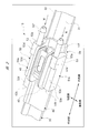
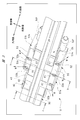
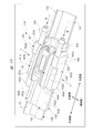
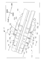
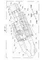
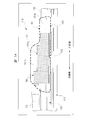
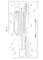
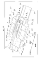
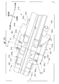
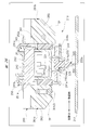
- FIG. 1 is a perspective view illustrating an entire wiper blade according to a first embodiment. It is the expansion perspective view which looked at the connection member periphery of the wiper blade of FIG. 1 from the front side. It is the expansion perspective view which looked at the connection member periphery of the wiper blade of FIG. 1 from the back side.
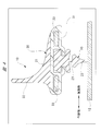
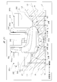
- FIG. 4 is a cross-sectional view taken along the line aa in FIG. 3.
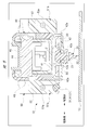
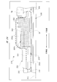
- FIG. 4 is a cross-sectional view taken along the line bb in FIG. 3.
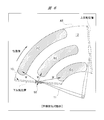
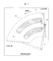
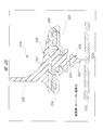
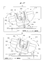
- FIG. 6 is an explanatory diagram for explaining the washer liquid injection positions (A2 to C2) in the outward path wiping operation. It is explanatory drawing explaining the spraying position (D2, E2) of the washer liquid in a return path side wiping operation.
- FIG. 4 is a cross-sectional view taken along the line aa in FIG. 3.
- FIG. 4 is a cross-sectional view taken along the line bb in FIG. 3.
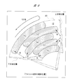
- FIG. 6 is an explanatory diagram for explaining
- FIG. 6 is an explanatory diagram for explaining a washer liquid ejection position (A2 to E2).
- FIG. 6 is a perspective view showing an entire wiper blade according to a second embodiment.
- FIG. 10 is an enlarged perspective view of the periphery of the connecting member of the wiper blade of FIG. 9 as viewed from the front side.
- FIG. 10 is an enlarged perspective view of the periphery of the connecting member of the wiper blade of FIG. 9 as viewed from the back side.
- It is an expansion perspective view explaining the fixation structure of a connection member and a washer apparatus. It is an enlarged view of the broken-line circle
- FIG. 12 is a cross-sectional view taken along the line dd in FIG. 11.
- FIG. 12 is a cross-sectional view taken along line ee in FIG. 11.
- FIG. 6 is a perspective view showing an entire wiper blade of a third embodiment. It is the expansion perspective view which looked at the connection member periphery of the wiper blade of FIG. 18 from the front side. It is the expansion perspective view which looked at the connection member periphery of the wiper blade of FIG. 18 from the back side.
- FIG. 19 is a view on arrow a in FIG. 18. It is an expansion perspective view explaining the fixation structure of a connection member and a washer apparatus. It is a b arrow line view of FIG. It is a c arrow line view of FIG. FIG.
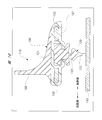
- FIG. 21 is a cross-sectional view taken along the line dd in FIG. 20.
- FIG. 21 is a cross-sectional view taken along the line ee of FIG. 20.
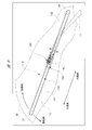
- (A), (b) is explanatory drawing explaining the inclination state to the wiping direction of a wiper blade.
- FIG. 1 is a perspective view showing the entire wiper blade of the first embodiment
- FIG. 2 is an enlarged perspective view of the periphery of the connecting member of the wiper blade of FIG. 1 from the front side
- FIG. 3 is a connecting member of the wiper blade of FIG.
- FIG. 4 is a cross-sectional view taken along the line aa in FIG. 3
- FIG. 5 is a cross-sectional view taken along the line bb in FIG. 3
- FIG. FIG. 7 is an explanatory diagram for explaining the washer liquid ejection positions (A2 to C2) in FIG. 7
- FIG. 7 is an explanatory diagram for explaining the washer liquid ejection positions (D2, E2) in the return-side wiping operation
- FIG. Explanatory diagrams for explaining the positions (A2 to E2) are respectively shown.
- the wiper blade 10 is rotatably attached to a tip end portion of a wiper arm 11 provided on the front side (not shown) of a vehicle such as an automobile.
- the wiper arm 11 is driven to swing as the wiper motor (not shown) is rotated by turning on a wiper switch (not shown) provided in the vehicle interior.
- the wiper blade 10 performs a reciprocating wiping operation toward a forward path side and a return path side as indicated by arrows in the figure, on a predetermined wiping range AR formed on the windshield (wind shield) 12.
- the wiper blade 10 is provided at a blade rubber 20 that is in contact with the windshield 12, a holder member 30 that holds the blade rubber 20, and an intermediate portion in the longitudinal direction of the holder member 30.
- a connecting member 40 and a washer device 50 provided on the connecting member 40 are provided.
- a pair of end caps CP are attached to both end portions of the holder member 30 in the longitudinal direction. Thereby, the blade rubber 20 held by the holder member 30 is prevented from coming off.
- the blade rubber 20 connects the main body portion 21 held by the holder member 30, the lip portion 22 in contact with the windshield 12, and the main body portion 21 and the lip portion 22. And a neck portion 23.
- the blade rubber 20 is formed in an elongated shape by extruding an elastic material such as rubber, and the cross-sectional shape thereof is uniform throughout the entire length.
- the thickness dimension of the neck portion 23 along the operation direction (the left-right direction in the drawing) of the blade rubber 20 is set to be thinner than the thickness dimensions of the main body portion 21 and the lip portion 22 and is easily elastically deformed.
- the holder member 30 includes a holder main body 31 and fin portions 32 as shown in FIGS.
- the holder main body 31 and the fin part 32 are integrated by two-color molding of different materials having different hardnesses, and are formed in a long shape like the blade rubber 20.
- the holder main body 31 is made of a flexible plastic or the like so as to be able to follow the curved shape (not shown) of the windshield 12 while ensuring sufficient strength to hold the main body portion 21 of the blade rubber 20. It is made of a resin material.
- the fin portion 32 is formed of an elastic material such as rubber having a hardness lower than that of the holder body 31. When the traveling wind hits the fin portion 32, down force is generated in the wiper blade 10, and thus the wiping performance of the blade rubber 20 is kept good.
- a pair of vertebras 33 are provided in the holder main body 31 at a predetermined interval.
- Each of the vertebras 33 is formed of a steel plate having a spring property, and is disposed so as to be a mirror image object so as to sandwich the main body 21 of the blade rubber 20 from the forward path side and the return path side.
- Each natural bra 33 is curved with a curvature larger than the curvature of the windshield 12 in a natural state where no external force is applied, and the holder member 30 and the blade rubber 20 are elastically deformed in accordance with the curvature of the windshield 12. It is like that. Thereby, the whole area along the longitudinal direction of the lip portion 22 is in close contact with the windshield 12.
- a connecting member 40 is provided in the longitudinal intermediate portion of the holder member 30.
- the connecting member 40 includes a connecting main body 41, a base plate 42, and a cover member 43.
- the connection main body 41 is formed into a substantially U-shaped cross section by pressing a steel plate or the like, and is fixed to each vertical bra 33 by a fixed leg portion (not shown) provided integrally.
- a cylindrical pin 44 made of a steel material is caulked and fixed to the connecting body 41, and a hook mounting member 45 formed of a resin material such as plastic is rotatably mounted on the cylindrical pin 44.
- a U-shaped hook (not shown) formed at the distal end portion of the wiper arm 11 is connected to the hook mounting member 45 by one touch. That is, the wiper arm 11 is connected to the connecting member 40.
- the base plate 42 is formed in a plate shape by a resin material such as plastic, and the base plate 42 is attached to each vertebra 33 by a fixed leg portion 42a provided integrally.
- the connection main body 41 is disposed on the fin portion 32 side (front side) of the holder member 30, and the base plate 42 is disposed on the holder main body 31 side (back side) of the holder member 30.
- the cover member 43 is formed in a substantially box shape from a resin material such as plastic, and is attached to the outside of the connection main body 41 by a plurality of integrally provided engaging claws (not shown).
- the cover member 43 covers the side surface portion of the connection main body 41 and the like, thereby improving the appearance of the wiper blade 10.
- a washer device 50 is provided at an intermediate portion in the longitudinal direction of the holder member 30.
- the washer device 50 is provided in the vicinity (see FIGS. 2 and 3) of the connecting portion CN between the wiper arm 11 and the wiper blade 10. More specifically, the washer device 50 is attached to the connecting member 40 that forms the connecting portion CN so as not to rattle through an engaging claw or the like (not shown).
- the washer device 50 includes an outward pass washer mechanism 51 a and a return pass washer mechanism 51 b so as to sandwich the blade rubber 20.
- the washer mechanisms 51 a and 51 b are respectively fixed to the connecting member 40, and the blade rubber 20 is centered. As a mirror image object.
- the length dimension along the longitudinal direction of the blade rubber 20 of the washer device 50 is set to be slightly shorter than the length dimension of the connecting member 40 along the longitudinal direction of the blade rubber 20.
- the forward pass washer mechanism 51a and the return pass washer mechanism 51b include an outward pass block 52 and a return pass block 53 having different shapes.
- Each of the forward path side flow path block 52 and the return path side flow path block 53 is formed in a stepped substantially box shape by a resin material such as plastic.
- the forward channel block 52 is provided on the forward side of the blade rubber 20 and includes an inner peripheral side wall 52a, an outer peripheral side wall 52b, a back side wall 52c, a front side wall 52d, and an outward path side wall 52e.
- the inner peripheral side wall 52a and the outer peripheral side wall 52b, and the back side wall 52c and the front side wall 52d are arranged to face each other, and the front side wall 52d is formed in a step shape as shown in FIG. .
- a plurality of forward-side injection nozzles A1, B1, and C1 are provided on the back side wall 52c that faces the windshield 12.
- three forward-side injection nozzles A 1, B 1, and C 1 are provided, and these forward-side injection nozzles A 1, B 1, and C 1 are arranged at substantially equal intervals along the longitudinal direction of the blade rubber 20. Is arranged in.
- each of the forward-side injection nozzles A1, B1, C1 is formed in a substantially spherical shape so that the injection direction of the washer liquid W (see FIGS. 3 and 6) can be adjusted.
- Each forward path injection nozzle A1, B1, C1 is directed to the forward path side of the blade rubber 20. More specifically, as shown in FIG. 3, the outward injection nozzle A1 on the outer peripheral side of the back side wall 52c is directed to the outer peripheral side of the blade rubber 20 on the outward path side. As a result, the outward injection nozzle A1 injects the washer fluid W to the injection position A2 in FIG. 6 when the wiper blade 10 performs the outward wiping operation. That is, the forward-side injection nozzle A ⁇ b> 1 is provided at a position that wets the outer peripheral side end on the one side (outer peripheral side) in the longitudinal direction of the blade rubber 20.
- the forward-side injection nozzle B1 in the middle portion in the longitudinal direction of the back side wall 52c is directed in the forward direction of the blade rubber 20 and in a direction orthogonal to the longitudinal direction of the blade rubber 20.
- the outward spray nozzle B1 injects the washer fluid W to the injection position B2 in FIG. 6 when the wiper blade 10 performs the outward wiping operation.
- the outward injection nozzle C1 on the inner peripheral side of the back side wall 52c is directed to the outer peripheral side of the blade rubber 20 and to the inner peripheral side.
- the outward spray nozzle C1 injects the washer fluid W to the injection position C2 in FIG. 6 when the wiper blade 10 performs the outward wiping operation. That is, the forward-side injection nozzle C ⁇ b> 1 is provided at a position that wets the inner peripheral side end on the other side (inner peripheral side) in the longitudinal direction of the blade rubber 20.
- injection positions A2 to C2 in FIG. 6 indicate positions where the wiper blade 10 is wetted by the washer liquid W as the wiper blade 10 moves to the forward path side, and as the wiper blade 10 moves toward the forward path side.
- a substantially arc-shaped injection range is formed.
- the forward-side injection nozzles A1 and C1 on both sides in the longitudinal direction of the blade rubber 20 are connected to one side in the longitudinal direction (outer peripheral side) of the blade rubber 20 and It is directed to the other side in the longitudinal direction (inner circumferential side). Therefore, as shown in FIG. 6, a relatively wide area inside the wiping range AR is wetted with the washer liquid W. If a diffusion type nozzle that sprays the washer liquid W in the form of a spray is used, a wider area inside the wiping range AR is wetted.
- the blade of the forward-side washer mechanism 51a The length dimension along the longitudinal direction of the rubber 20 can be shortened. Therefore, the flow path through which the washer liquid W passes before being jetted can be made shorter than before. Therefore, it is possible to suppress power consumption of a washer pump (not shown) while suppressing freezing of the washer liquid W.
- the return-side flow path block 53 is provided on the return path side of the blade rubber 20 and includes an inner peripheral side wall 53a, an outer peripheral side wall 53b, a back side wall 53c, a front side wall 53d, and a return side wall 53e.
- the inner peripheral side wall 53a and the outer peripheral side wall 53b, and the back side wall 53c and the front side wall 53d are arranged to face each other, and the front side wall 53d is formed in a stepped shape as shown in FIG. .
- the back side wall 53c facing the windshield 12 is provided with a plurality of return side injection nozzles D1, E1.
- the first embodiment two return-side injection nozzles D1 and E1 are provided, and each of the return-side injection nozzles D1 and E1 extends along the longitudinal direction of the blade rubber 20.
- C1 are arranged side by side at substantially the same interval.
- one return-side injection nozzle D1 is disposed between the forward-side injection nozzles A1 and B1 along the longitudinal direction of the blade rubber 20, and the other return-side injection nozzle E1 is along the longitudinal direction of the blade rubber 20. It arrange
- Each return side injection nozzle D1, E1 is directed to the return side of the blade rubber 20. More specifically, as shown in FIG. 3, the return side injection nozzle D1 on the outer peripheral side of the back side wall 53c is directed to the return side of the blade rubber 20 and to the outer peripheral side. As a result, the return-side injection nozzle D1 injects the washer fluid W to the injection position D2 in FIG. 7 when the wiper blade 10 performs the return-side wiping operation.
- the return side injection nozzle E1 on the inner peripheral side of the back side wall 53c is directed to the return side of the blade rubber 20 and to the inner peripheral side.
- the inward-side injection nozzle E1 injects the washer fluid W to the injection position E2 in FIG. 7 when the wiper blade 10 performs the inward-side wiping operation.
- injection positions D2 and E2 in FIG. 7 indicate positions where the wiper blade 10 is wetted by the washer fluid W as the wiper blade 10 moves toward the return path, and as the wiper blade 10 moves toward the return path.
- a substantially arc-shaped injection range is formed.
- the return-side injection nozzles D1 and E1 on both sides in the longitudinal direction of the blade rubber 20 are directed to one side (outer peripheral side) in the longitudinal direction and the other side (inner peripheral side) in the longitudinal direction of the blade rubber 20, respectively. Therefore, as shown in FIG. 8, the space between the spray positions A2 and B2 and the position between the spray positions B2 and C2 inside the wiping range AR is wetted with the washer liquid W.
- the injection positions A2, B2, and C2 of the washer liquid W injected from the forward path injection nozzles A1, B1, and C1, and the injection positions D2 of the washer liquid W that are injected from the backward path injection nozzles D1 and E1. , E2 are shifted in the longitudinal direction of the blade rubber 20.
- the injection positions are alternately arranged as A2, D2, B2, E2, and C2, and the injection positions A2 to E2 on the windshield 12 on the forward path side and the return path side of the blade rubber 20 are illustrated in FIG. As shown in FIG.
- Outward-side injection nozzle A1 that is closest to the outer peripheral side of blade rubber 20 in C1 is arranged closer to the outer peripheral side of blade rubber 20.
- Outward-side injection nozzles C1 that are closest to the inner peripheral side of the blade rubber 20 out of C1 are arranged closer to the inner peripheral side of the blade rubber 20.
- the windshield 12 can be evenly wetted in the wiping operation for one reciprocation of the blade rubber 20.
- the length dimension along the longitudinal direction of the blade rubber 20 of the return pass washer mechanism 51b can be shortened similarly to the forward pass washer mechanism 51a, so that the flow path through which the washer fluid W passes before being jetted. Can be made shorter than before. Therefore, the power consumption of the washer pump can be suppressed while the freezing of the washer liquid W is suppressed.
- the forward side tube insertion part 52 f and the backward side tube insertion part 53 f are provided on the inner peripheral side wall 52 a of the forward path side flow path block 52 and the inner peripheral side wall 53 a of the return path side flow path block 53. Each is provided integrally. One end side of a rubber tube (not shown) is inserted into each of the forward side tube insertion part 52f and the return side tube insertion part 53f.
- the washer pump installed in the engine room of the vehicle is connected to the other end of the rubber tube.
- the rubber tube is disposed on the inner peripheral side along the longitudinal direction of the blade rubber 20, thereby facilitating introduction of the other end side of the rubber tube into the engine room.
- the washer pump is driven by operating the washer switch, so that the washer liquid W is passed through the rubber tube and the forward path side block 52 and the return path side as shown by the two-dot chain line arrows in FIGS. It is supplied into the flow path block 53.
- the drive of the washer pump is switched, so that the washer liquid W is supplied only to the forward flow path block 52 during the forward wiping operation of the wiper blade 10, and the backward flow path block 53 during the backward wiping operation of the wiper blade 10. Only the washer liquid W is supplied.
- the outward wiping operation refers to an operation in which the wiper blade 10 moves the wiping range AR on the windshield 12 upward from the lower inversion position and then moves to the upper inversion position.
- the return-side wiping operation means that the wiper blade 10 moves in the wiping range AR on the windshield 12 from the upper reverse position shown in FIG. 7 to the lower position, and then moves to the lower reverse position. Say what you do.
- the washer liquid W is discharged from the return path injection nozzles D1 and E1. Be injected.
- the injection positions D2 and E2 are between the injection positions A2 and B2 and between the injection positions B2 and C2, which correspond to portions that are insufficiently wet during the outward wiping operation. Therefore, as shown in the injection positions A2 to E2 in FIG. 8, in the wiping operation for one reciprocation of the blade rubber 20 (wiper blade 10), the windshield 12 is uniformly wetted and can be wiped. Thereby, the deposits such as dust on the windshield 12 can be wiped cleanly.
- the portions other than the injection positions D2 and E2 shown in FIG. 7 are wet during the outward wiping operation, and a little washer fluid W is supplied by the traveling wind of the vehicle and the like. Therefore, the occurrence of problems due to dry contact of the wiper blade 10 with the windshield 12 is suppressed even during the return-side wiping operation.
- the number (three) of the forward-side injection nozzles A1, B1, and C1 is made larger than the number (two) of the backward-side injection nozzles D1 and E1.
- the amount of the washer liquid W during the outward wiping operation is made larger than the amount of the washer liquid W during the backward wiping operation. This is because the stop position of the wiper blade 10 is the lower inversion position, and at the beginning of the operation of the wiper blade 10, it is desirable to wet the surface of the dry windshield 12 as widely as possible.
- the injection positions A2, B2, C2 of the washer liquid W injected from the forward injection nozzles A1, B1, C1, and the return paths are shifted in the longitudinal direction of the blade rubber 20 and arranged alternately.
- the injection positions A2 to E2 on the windshield 12 are made different on the forward path side and the return path side of the blade rubber 20 to alternate, and as a result, in the wiping operation for one reciprocation of the blade rubber 20, the windshield 12 is evenly wetted. be able to. Accordingly, the total number of injection nozzles can be reduced as compared with the conventional case (five in the first embodiment), and the consumption of the washer liquid W during the reciprocating wiping operation of the blade rubber 20 can be suppressed. Therefore, it is possible to reduce the power consumption of the washer pump and to reduce the size of the washer pump.
- the wiper blade 10 wipes the windshield 12 as the windshield.
- the present invention is not limited to this, and the wiper blade 10 also wipes the rear glass as the windshield. Can be applied.
- the spray position of the washer liquid W sprayed from the forward path side injection nozzle and the spray position of the washer liquid W sprayed from the backward path side spray nozzle can be shifted in the longitudinal direction of the blade rubber 20 or alternately. Can be provided one by one on the forward path side and the return path side, or a total of six or more may be provided on the forward path side and the return path side.
- the forward side injection nozzles A1, B1, C1 are provided on the back side wall 52c, and the return side injection nozzles D1, E1 are provided on the back side wall 53c.
- the forward side injection nozzles A1, B1, and C1 may be provided on the forward side wall 52e, and the backward side injection nozzles D1 and E1 may be provided on the return side wall 53e.
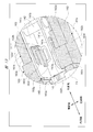
- FIG. 9 is a perspective view showing the entire wiper blade of the second embodiment
- FIG. 10 is an enlarged perspective view of the periphery of the connecting member of the wiper blade of FIG. 9 from the front side
- FIG. 11 is a connecting member of the wiper blade of FIG.
- FIG. 12 is an enlarged perspective view of the periphery seen from the back side
- FIG. 12 is an enlarged perspective view for explaining a fixing structure between the connecting member and the washer device
- FIG. 13 is an enlarged view of a broken line circle a part of FIG.
- FIG. 15 is a cross-sectional view taken along the line dd in FIG. 11, and
- FIG. 17 is a cross-sectional view taken along the line ee in FIG. Respectively.
- the wiper blade 110 is rotatably attached to a tip end portion of a wiper arm 111 provided on the front side (not shown) of a vehicle such as an automobile.
- the wiper arm 111 is driven to swing as the wiper motor (not shown) is rotated by turning on a wiper switch (not shown) provided in the vehicle interior.
- the wiper blade 110 performs a reciprocating wiping operation on a predetermined wiping range AR formed on the windshield (wind shield) 112 toward the forward path and the backward path as indicated by arrows in the figure.
- the wiper blade 110 is provided at a blade rubber 120 that is in contact with the windshield 112, a holder member 130 that holds the blade rubber 120, and an intermediate portion in the longitudinal direction of the holder member 130.
- the connecting member 140 includes a cover member 150 that covers the connecting member 140, and a washer device 160 fixed to the connecting member 140.
- a pair of end caps CP are attached to both ends of the holder member 130 in the longitudinal direction. Thereby, the blade rubber 120 held by the holder member 130 is prevented from coming off.
- the blade rubber 120 connects the main body 121 held by the holder member 130, the lip 122 that contacts the windshield 112, and the main body 121 and the lip 122. And a neck portion 123.
- the blade rubber 120 is formed in an elongated shape by extruding an elastic material such as rubber, and the cross-sectional shape thereof is uniform throughout the entire length direction.
- the thickness dimension of the neck portion 123 along the operation direction (the left-right direction in the drawing) of the blade rubber 120 is set to a thickness dimension thinner than the thickness dimension of the main body 121 and the lip portion 122 and is easily elastically deformed.
- the holder member 130 includes a holder main body 131 and a fin portion 132 as shown in FIGS. 9, 10, and 16.
- the holder main body 131 and the fin portion 132 are integrated by two-color molding of different materials having different hardnesses, and are formed to be long like the blade rubber 120.
- the holder main body 131 is made of a flexible plastic or the like so as to be able to follow the curved shape (not shown) of the windshield 112 while ensuring sufficient strength to hold the main body 121 of the blade rubber 120. It is made of a resin material.
- the fin portion 132 is formed of an elastic material such as rubber having a hardness lower than that of the holder main body 131. That is, the holder member 130 provided with the holder main body 131 and the fin part 132 has elasticity. When the traveling wind hits the fin portion 132, down force is generated in the wiper blade 110, so that the wiping performance of the blade rubber 120 is kept good.
- Each vertical bra 133 is formed of a steel plate having a spring property, and is disposed so as to be a mirror image target so that the main body 121 of the blade rubber 120 is sandwiched from the forward path side and the backward path side.
- Each natural bra 133 is curved with a curvature larger than the curvature of the windshield 112 in a natural state where no external force is applied, and the holder member 130 and the blade rubber 120 are elastically deformed in accordance with the curvature of the windshield 112. It is like that. Thereby, the whole area along the longitudinal direction of the lip portion 122 is in close contact with the windshield 112.
- a connecting member 140 is provided at an intermediate portion in the longitudinal direction of the holder member 130.
- the connecting member 140 includes a connecting main body 141, a cylindrical pin 142, a hook mounting member 143, and a base plate 144 that are higher in rigidity than the holder member 130.
- the cross section of the connecting body 141 is formed in a substantially U shape by pressing a steel plate.
- the connection main body 141 includes a bottom wall portion 141a, and a forward side wall portion 141b and a return side wall portion 141c that are integrally provided on the bottom wall portion 141a and are opposed to each other.
- a plurality of fixed leg portions 141d are integrally provided on the bottom wall portion 141a. By fixing these fixed leg portions 141d to the respective vertical bars 133, the connection main body 141 It is firmly fixed to the vertical bra 133.
- the connection main body 141 has a function of holding the vertebras 133 at predetermined intervals.
- a cylindrical pin 142 made of a steel material is caulked and fixed between the outward side wall 141b and the return side wall 141c.
- a hook mounting member 143 formed in a predetermined shape by a resin material such as plastic is rotatably mounted on the cylindrical pin 142.
- a U-shaped hook (not shown) formed at the tip of the wiper arm 111 is connected to the hook mounting member 143 with one touch. That is, the wiper arm 111 is connected to the connecting member 140.
- the forward path side wall 141b and the return path side wall 141c are provided with an outward path side mounting hole 141e and a return path side mounting hole 141f as mounting holes that are opened in a direction intersecting (orthogonal) with the longitudinal direction of the blade rubber 120, respectively. Yes.
- each of the outward path side mounting hole 141 e and the return path side mounting hole 141 f is formed in a substantially rectangular shape, and is opposed to each other from the direction intersecting the longitudinal direction of the blade rubber 120.
- the positioning claws 162g and 163g and the retaining claws 162h and 163h of the forward path side flow path block 162 and the backward path side flow path block 163 are inserted and fixed in the forward path side mounting hole 141e and the backward path side mounting hole 141f, respectively. It is like that.
- the base plate 144 is formed in a plate shape from a resin material such as plastic, and the base plate 144 is integrally provided with a plurality of fixed leg portions 144a.
- Each fixed leg portion 144 a of the base plate 144 is attached to each vertebra 133, so that the base plate 144 is fixed to each vertebra 133.
- the connection main body 141 is disposed on the fin portion 132 side (front side) of the holder member 130, and the base plate 144 is disposed on the holder main body 131 side (back side) of the holder member 130.
- the cover member 150 is formed in a substantially box shape from a resin material such as plastic, and is connected by a plurality of integrally provided engaging claws (not shown). It is attached to the main body 141.
- the cover member 150 is provided between the connecting member 140 and the washer device 160 in a direction crossing the longitudinal direction of the blade rubber 120, and covers the periphery of the connecting body 141 constituting the connecting member 140. A gap between the connecting member 140 and the washer device 160 is filled. Thereby, the appearance of the wiper blade 110 is improved.
- the cover member 150 includes an outward path side cover portion 151 and an inward path side cover portion 152, and the forward path side cover portion 151 and the backward path side cover portion 152 are integrated with an imaginary line L shown in FIG. ing.
- the forward path side cover portion 151 is provided so as to be sandwiched between the forward path side wall portion 141b and the forward path side flow path block 162 (see FIG. 13), and the return path side cover portion 152 includes the return path side wall portion 141c and the return path side wall portion 162c. It is provided so as to be sandwiched between the flow path block 163 (see FIG. 13).
- the forward path side cover portion 151 extends in the longitudinal direction of the blade rubber 120 from the forward path side covering portion 151a that covers the outer surface of the outward path side wall portion 141b, and is similar to the fin portion 132 of the holder member 130. And fin-shaped portion 151b formed in the shape.
- the return-side cover 152 is a return-side covering 152a that covers the outer surface of the return-side wall 141c, and extends from the return-side covering 152a in the longitudinal direction of the blade rubber 120. And a holder main body-like part 152b formed in the same shape.
- the aerodynamic resistance of the portion where the cover member 150 is provided and the holder member 130 where the cover member 150 is not provided is made to be substantially the same value.
- a washer device 160 is provided at an intermediate portion in the longitudinal direction of the holder member 130.
- the washer device 160 is shaded.
- the washer device 160 includes an outward pass washer mechanism 161a and a return pass washer mechanism 161b so as to sandwich the connecting body 141 therebetween. These washer mechanisms 161 a and 161 b are respectively fixed to the connection main body 141, and are disposed so as to face each other as a mirror image object around the blade rubber 120.
- each of the washer mechanisms 161 a and 161 b constituting the washer device 160 includes a forward cover portion 151 and a cover portion 151 in the cover member 150 in a plan view from a direction intersecting the longitudinal direction of the blade rubber 120. It is provided within the range of the projected area of the return side cover 152, that is, inside the broken lines (1) and (2) shown in FIGS.
- the washer device 160 within the range of the projected area of the cover member 150, it is possible to suppress disturbance of traveling wind (not shown) flowing from the return path side of the wiper blade 110, for example, the front side of the vehicle.
- traveling wind not shown
- the wiping performance of the blade rubber 120 is prevented from being deteriorated.
- the forward pass washer mechanism 161a and the return pass washer mechanism 161b are provided with an outward pass channel block 162 and a return pass channel block 163 having different shapes.
- the forward path side flow path block 162 and the return path side flow path block 163 are each formed in a stepped substantially box shape by a resin material such as plastic.
- the length of the outgoing path side flow path block 162 along the longitudinal direction of the blade rubber 120 is longer than that of the return path side flow path block 163. This is because the projected area of the forward path side cover portion 151 (see the broken line (1) in FIG. 14) is larger than the projected area of the backward path side cover portion 152 (see the broken line (2) in FIG. 15).
- the forward path side flow path block 162 is provided on the forward path side of the blade rubber 120 and includes an inner peripheral side wall 162a, an outer peripheral side wall 162b, a back side wall 162c, a front side wall 162d, an outward path side wall 162e, and a connecting main body side wall 162f.
- the inner peripheral side wall 162a and the outer peripheral side wall 162b, the back side wall 162c and the front side wall 162d, the forward path side wall 162e, and the connection main body side wall 162f are arranged to face each other, and the front side wall 162d is as shown in FIG. Are formed in three steps.
- a positioning claw 162g and a retaining claw 162h are integrally provided on the connection main body side wall 162f of the forward path side flow path block 162 so as to protrude toward the connection main body 141.
- the positioning claws 162g and the retaining claws 162h constitute a fixing claw in the present invention, and both are fixed by being inserted into the forward path side mounting hole 141e and being hooked on the forward path side wall 141b. ing.
- the positioning claw 162g and the retaining claw 162h are not shown in detail, they are formed in the same shape as the positioning claw 163g and the retaining claw 163h of the return path passage block 163 described later.
- the return side flow path block 163 is provided on the return side of the blade rubber 120 and includes an inner peripheral side wall 163a, an outer peripheral side wall 163b, a back side wall 163c, a front side wall 163d, a return side wall 163e, and a connecting main body side wall 163f.
- the inner peripheral side wall 163a and the outer peripheral side wall 163b, the back side wall 163c and the front side wall 163d, the return side wall 163e, and the connecting main body side wall 163f are arranged to face each other, and the front side wall 163d is as shown in FIG. Are formed in two steps.
- a positioning claw 163g and a retaining claw 163h are integrally provided on the connection main body side wall 163f of the return-side flow path block 163 so as to protrude toward the connection main body 141.
- the positioning claw 163g and the retaining claw 163h constitute a fixing claw according to the present invention, both of which are fixed by being inserted into the return side mounting hole 141f and hooked on the return side wall portion 141c. ing.
- the positioning claws 162g and 163g are connected to the forward path mounting hole 141e and the return path mounting hole. 141f is inserted and hooked from an oblique direction.
- the forward path side flow path block 162 and the return path side flow path block 163 are positioned with respect to the forward path side wall portion 141b and the return path side wall portion 141c. That is, the positioning claws 162g and 163g perform positioning with respect to the connecting member 140 of the washer device 160.
- the retaining claws 162h and 163h are inserted and hooked into the forward path side mounting hole 141e and the backward path side mounting hole 141f from the direction intersecting the longitudinal direction of the blade rubber 120.
- the forward-side flow path block 162 and the backward-side flow path block 163 are prevented from being detached from the forward-path side wall portion 141b and the backward-path side wall portion 141c. Fixing to is completed. That is, the retaining claws 162h and 163h prevent the washer device 160 from being detached from the connecting member 140.
- the fixing holes 141e and 141f, the positioning claws 162g and 163g, and the retaining claws 162h and 163h can be firmly fixed with substantially one touch without using a fixing means such as an adhesive.
- a fixing means such as an adhesive
- the forward-side flow path block 162 and the return-path side flow path block 163 are each fixed to the connection main body 141 after the cover member 150 is attached to the connection main body 141. That is, the washer device 160 is fixed to the connecting member 140 via the cover member 150. In this way, the cover member 150 is firmly fixed to the connecting member 140 together with the washer device 160 without rattling. Accordingly, the cover member 150 that conceals the connecting member 140 and improves the appearance is firmly fixed to the connecting member 140 together with the washer device 160, thereby improving the assembly of the wiper blade 110 and the wiper blade 110. It is possible to realize both suppression of rattling of the constituent parts.
- a plurality of forward-side injection nozzles A, B, and C are provided on the back side wall 162c of the forward-side flow path block 162 so as to face the windshield 112.
- three forward injection nozzles A, B, and C are provided, and these forward injection nozzles A, B, and C are arranged at substantially equal intervals along the longitudinal direction of the blade rubber 120. Is arranged in.
- each of the forward-side injection nozzles A, B, and C is formed in a substantially spherical shape so that the injection direction of the washer liquid W (see FIG. 11) can be adjusted.
- Each forward path injection nozzle A, B, C is directed to the forward path side of the blade rubber 120. More specifically, as shown in FIG. 11, the outward injection nozzle A on the outer peripheral side of the back side wall 162c is directed to the outer peripheral side of the blade rubber 120 on the outward path side.
- the forward injection nozzle B in the middle portion in the longitudinal direction of the back side wall 162c is directed in the forward direction of the blade rubber 120 and in a direction (straight side) perpendicular to the longitudinal direction of the blade rubber 120.
- the outward injection nozzle C located on the inner peripheral side of the back side wall 162c is directed to the outer peripheral side of the blade rubber 120 and to the inner peripheral side.
- the wide range inside the wiping range AR is wetted by the washer liquid W by each of the forward spray nozzles A, B, and C, and the length dimension along the longitudinal direction of the blade rubber 120 of the forward pass washer mechanism 161a is set. It is shortened. Therefore, the flow path through which the washer liquid W is passed can be shortened, and as a result, the power consumption of the washer pump (not shown) can be suppressed while the freezing of the washer liquid W is suppressed. .
- a plurality of return-side injection nozzles D and E are provided on the back side wall 163 c of the return-side flow path block 163 so as to face the windshield 112.
- two return-side injection nozzles D and E are provided, and each of the return-side injection nozzles D and E extends along the longitudinal direction of the blade rubber 120. , C are arranged side by side at substantially the same interval.
- one return-side injection nozzle D is disposed between the forward-side injection nozzles A and B along the longitudinal direction of the blade rubber 120, and the other return-side injection nozzle E is along the longitudinal direction of the blade rubber 120. It arrange
- each of the backward injection nozzles D and E is formed in a substantially spherical shape like each of the outward injection nozzles A, B, and C, so that the injection direction of the washer liquid W (see FIG. 11) can be adjusted. ing.
- Each return side injection nozzle D, E is directed to the return side of the blade rubber 120. More specifically, as shown in FIG. 11, the return-side injection nozzle D on the outer peripheral side of the back side wall 163 c is directed to the return side of the blade rubber 120 and to the outer peripheral side. On the other hand, the return side injection nozzle E on the inner peripheral side of the back side wall 163c is directed to the return side of the blade rubber 120 and to the inner peripheral side.
- the return-side injection nozzles D and E are directed in the two directions of the return side of the blade rubber 120 and the outer peripheral side and the inner peripheral side, so that the vicinity of the return side of the blade rubber 120 is substantially evenly wetted. I am doing so.
- the return side injection nozzles D and E it is possible to wet a wider range inside the wiping range AR by adopting a diffusion type nozzle.
- the length dimension along the longitudinal direction of the blade rubber 120 of the return pass washer mechanism 161b is shortened in the same manner as the forward pass washer mechanism 161a. Therefore, also in the return-side washer mechanism 161b, the flow path through which the washer liquid W passes can be shortened, so that the power consumption of the washer pump can be suppressed while the freezing of the washer liquid W is suppressed. It has become.
- the respective injection positions are staggered along the longitudinal direction of the blade rubber 120. Accordingly, the windshield 112 is wetted evenly in the wiping operation accompanied by the washer liquid injection for one reciprocation of the blade rubber 120. As a result, a wide range on the windshield 112 can be cleaned cleanly in a wiping operation involving the injection of the washer liquid W during one reciprocation of the blade rubber 120.
- FIG. 10 and FIG. 11 As shown in FIG. 10 and FIG. 11, as shown in FIG. 10 and FIG. 11, as shown in FIG. 10 and FIG. Each is provided integrally.
- One end side of the rubber tube TB shown in FIG. 12 is inserted into each of the forward tube insertion portion 162i and the backward tube insertion portion 163i.
- the washer pump installed in the engine room of the vehicle is connected to the other end of the rubber tube TB.
- the rubber tube TB is disposed on the inner peripheral side along the longitudinal direction of the blade rubber 120, thereby facilitating introduction of the other end side of the rubber tube TB into the engine room.
- the washer pump is driven by operating the washer switch, so that the washer liquid W is passed through the rubber tube TB and the outward path block 162 and the return path as shown by the two-dot chain arrows in FIGS. It is supplied to the inside of the side flow path block 163.
- the washer liquid W is supplied only to the forward-side flow path block 162 during the forward-wiping operation of the wiper blade 110, and the backward-side flow path block 163 during the backward-wiping operation of the wiper blade 110. Only the washer liquid W is supplied.
- the mounting holes 141e and 141f are positioned in the connecting member 140 that is higher in rigidity than the holder member 130 and to which the wiper arm 111 is connected.
- the washer device 160 is fixed by the claws 162g and 163g and the retaining claws 162h and 163h.
- the rigidity of the connecting member 140 is high because the wiper arm 111 is connected (made of a steel plate), and thus the washer device 160 can be firmly fixed to the connecting member 140. Therefore, it is possible to stabilize the spray position of the washer liquid W.
- the present invention is not limited to the second embodiment and can be variously modified without departing from the gist thereof.
- the wiper blade 110 wipes the windshield 112 as the windshield.
- the present invention is not limited to this, and the wiper blade 110 wipes the rear glass as the windshield. Can be applied.
- the present invention is not limited to this.
- the number of the forward-side injection nozzles and the number of the backward-side injection nozzles may be the same. This number may be larger than the number of forward-side injection nozzles.
- the forward side injection nozzles A, B, C are provided on the back side wall 162c, and the return side injection nozzles D, E are provided on the back side wall 163c.
- the forward-side injection nozzles A, B, and C may be provided on the forward-side wall 162e, and the backward-side injection nozzles D and E may be provided on the backward-side wall 163e.
- FIG. 18 is a perspective view showing the entire wiper blade of the third embodiment
- FIG. 19 is an enlarged perspective view of the periphery of the connection member of the wiper blade of FIG. 18 from the front side
- FIG. 20 is the connection member of the wiper blade of FIG.
- FIG. 21 is an enlarged perspective view of the periphery as seen from the back side
- FIG. 21 is a perspective view of FIG. 18,
- FIG. 22 is an enlarged perspective view illustrating a fixing structure between the connecting member and the washer device
- FIG. 24 is a cross-sectional view taken along the line dd in FIG. 20
- FIG. 26 is a cross-sectional view taken along the line ee in FIG. 27 (a) and 27 (b) are explanatory views for explaining the state of the wiper blade inclined in the wiping direction, respectively.
- the wiper blade 210 is rotatably mounted on the tip of a wiper arm 211 provided on the front side (not shown) of a vehicle such as an automobile.
- the wiper arm 211 is driven to swing as the wiper motor (not shown) rotates by turning on a wiper switch (not shown) provided in the vehicle interior. Accordingly, the wiper blade 210 performs a reciprocating wiping operation toward a forward path side and a return path side as indicated by arrows in the figure, on a predetermined wiping range AR formed on the windshield (wind shield) 212.
- the wiper blade 210 is provided in a blade rubber 220 that is in contact with the windshield 212, a holder member 230 that holds the blade rubber 220, and an intermediate portion in the longitudinal direction of the holder member 230.
- the connecting member 240 includes a cover member 250 that covers the connecting member 240, and a washer device 260 fixed to the connecting member 240.
- the blade rubber 220 connects the main body part 221 held by the holder member 230, the lip part 222 in contact with the windshield 212, and the main body part 221 and the lip part 222. And a neck portion 223.
- the blade rubber 220 is formed in an elongated shape by extruding an elastic material such as rubber, and the cross-sectional shape thereof is uniform throughout the entire length.
- a flat contact portion 222 a that is in contact with the windshield 212 is provided on the tip portion of the lip portion 222, that is, on the windshield 212 side of the lip portion 222.
- the contact portion 222a is in contact with the entire surface as shown in FIGS. It is like that.
- the thickness dimension of the neck portion 223 along the operation direction (left and right direction in the drawing) of the blade rubber 220 is set to a thickness dimension thinner than the thickness dimension of the main body portion 221 and the lip portion 222 and is easily elastically deformed.
- the lip portion 222 is allowed to be inclined so that the lip portion 222 can smoothly follow the moving direction of the wiper blade 210. (See FIG. 27). Therefore, it is possible to reliably wipe off deposits (not shown) such as rainwater and dust attached to the windshield 212.
- the holder member 230 includes a holder main body 231 and a fin portion 232.
- the holder main body 231 and the fin portion 232 are integrated by two-color molding of dissimilar materials having different hardnesses, and are formed long like the blade rubber 220.
- the holder main body 231 is made of a flexible plastic or the like so as to be able to follow the curved shape (not shown) of the windshield 212 while ensuring sufficient strength to hold the main body 221 of the blade rubber 220. It is made of a resin material.
- the fin portion 232 is formed of an elastic material such as rubber having a hardness lower than that of the holder body 231. When the traveling wind hits the fin portion 232, down force is generated in the wiper blade 210, whereby the wiping performance of the blade rubber 220 is maintained well.
- a pair of vertebras 233 are provided in the holder main body 231 at a predetermined interval.
- Each of the vertebras 233 is formed of a steel plate having a spring property, and is disposed so as to be a mirror image object so as to sandwich the main body portion 221 of the blade rubber 220 from the forward path side and the return path side.
- Each natural bra 233 is curved with a curvature larger than the curvature of the windshield 212 in a natural state where no external force is applied, and the holder member 230 and the blade rubber 220 are elastically deformed in accordance with the curvature of the windshield 212. It is like that. Thereby, the whole area along the longitudinal direction of the lip part 222 is brought into close contact with the windshield 212.
- a pair of end caps 234 are attached to both ends of the holder member 230 in the longitudinal direction. Thereby, the blade rubber 220 held by the holder member 230 is prevented from coming off.
- a spacer member 235 (only one of them is shown in the figure) is attached to each end cap 234 on the blade rubber 220 side.
- the side surface (front side in the figure) of the spacer member 235 is formed in a gentle arc shape, and the traveling wind flowing from the front side (right side in the figure) of the blade rubber 220 is moved behind the blade rubber 220 (in the figure). (Left side) can escape smoothly.
- the holder member 230 includes a holder main body 231, fin portions 232, each vertical bra 233, an end cap 234, and a spacer member 235.
- the spacer member 235 constituting the holder member 230 is disposed closest to the windshield 212 of the holder member 230 and forms a boundary portion in the present invention. More specifically, as shown in FIG. 21, when the wiper blade 210 is viewed in a plane perpendicular to the longitudinal direction of the blade rubber 220, a boundary portion is formed between the spacer member 235 and the blade rubber 220.
- BL is formed.
- the position of the boundary portion BL from the windshield 212 is set to a height dimension H.
- the height dimension H of the boundary portion BL is a height dimension lower than the height dimensions h1 and h2 of a washer device 260 (outward flow path block 262, return path flow path block 263) to be described later (H ⁇ H2 ⁇ h1).
- a connecting member 240 is provided in the vicinity of the connecting portion between the holder member 230 and the wiper arm 211 in the middle portion in the longitudinal direction of the holder member 230.
- the connecting member 240 includes a connecting body 241, a cylindrical pin 242, a hook mounting member 243, and a base plate 244.
- the cross section of the connecting body 241 is formed in a substantially U shape by pressing a steel plate.
- the connection main body 241 includes a bottom wall portion 241a and a forward side wall portion 241b and a return side wall portion 241c that are integrally provided on the bottom wall portion 241a and are disposed to face each other.
- a plurality of fixed leg portions 241d are integrally provided on the bottom wall portion 241a, and by fixing these fixed leg portions 241d to the vertical bars 233, the connection main body 241 It is firmly fixed to the vertebra 233.
- the connection main body 241 has a function of holding the vertebras 233 at a predetermined interval.
- a cylindrical pin 242 made of steel is caulked and fixed between the outward side wall 241b and the backward side wall 241c. Further, a hook mounting member 243 formed in a predetermined shape by a resin material such as plastic is rotatably mounted on the cylindrical pin 242.
- a U-shaped hook (not shown) formed at the distal end portion of the wiper arm 211 is connected to the hook mounting member 243 with one touch. That is, the wiper arm 211 is connected to the connecting member 240.
- the forward side wall part 241b and the backward side wall part 241c are respectively provided with an outward path side mounting hole 241e and a backward path side mounting hole 241f that are opened in a direction intersecting (orthogonal) with the longitudinal direction of the blade rubber 220.
- the forward path side mounting hole 241e and the return path side mounting hole 241f are each formed in a substantially rectangular shape, and are opposed to each other from the direction intersecting the longitudinal direction of the blade rubber 220.
- the positioning claws 262g, 263g and the retaining claws 262h, 263h of the forward path flow path block 262 and the backward path flow path block 263 are inserted and fixed in the forward path side mounting hole 241e and the backward path side mounting hole 241f, respectively. It is like that.
- the base plate 244 is formed in a plate shape from a resin material such as plastic, and the base plate 244 is integrally provided with a plurality of fixed leg portions 244a.
- Each fixed leg portion 244 a of the base plate 244 is attached to each vertebra 233, whereby the base plate 244 is fixed to each vertebra 233.
- the connection main body 241 is disposed on the fin portion 232 side (front side) of the holder member 230, and the base plate 244 is disposed on the holder main body 231 side (back side) of the holder member 230.
- the cover member 250 is formed in a substantially box shape from a resin material such as plastic, and is connected by a plurality of integrally provided engaging claws (not shown). It is mounted on the main body 241.
- the cover member 250 covers the periphery of the connection main body 241 constituting the connection member 240, thereby improving the appearance of the wiper blade 210.
- the cover member 250 includes an outward path side cover part 251 and a return path side cover part 252, and these forward path side cover part 251 and return path side cover part 252 are integrated with an imaginary line L shown in FIG. 19 as a boundary. ing.
- the forward side cover 251 is provided so as to be sandwiched between the forward side wall 241b and the forward side flow path block 262 (see FIG. 22), and the return side cover 252 is provided between the return side wall 241c and the return side. It is provided so as to be sandwiched between the flow path block 263 (see FIG. 22).
- the outward path side cover portion 251 extends in the longitudinal direction of the blade rubber 220 from the outward path side covering portion 251a that covers the outer surface of the outward path side wall portion 241b, and is similar to the fin portion 232 of the holder member 230. And a fin-shaped portion 251b formed in the shape.
- the return path side cover portion 252 extends in the longitudinal direction of the blade rubber 220 from the return path side covering portion 252a that covers the outer surface of the return side wall portion 241c, and the holder body 231 of the holder member 230. And a holder main body portion 252b formed in the same shape.
- the aerodynamic resistance of the portion where the cover member 250 is provided and the holder member 230 where the cover member 250 is not provided is made to be substantially the same value.
- a washer device 260 is fixed near the connecting portion between the holder member 230 and the wiper arm 211 in the longitudinal intermediate portion of the holder member 230.
- the washer device 260 is shaded in order to make it easy to understand the arrangement state of the washer device 260.
- the washer device 260 includes an outward pass washer mechanism 261a and a return pass washer mechanism 261b with the connecting body 241 interposed therebetween. These washer mechanisms 261 a and 261 b are respectively fixed to the connection main body 241 of the connection member 240, and are opposed to each other so as to be a mirror image centering on the blade rubber 220.
- each of the washer mechanisms 261a and 261b constituting the washer device 260 has a forward cover portion 251 in the cover member 250 and a plan view from a direction intersecting with the longitudinal direction of the blade rubber 220. It is provided within the range of the projected area of the return path side cover 252, that is, inside the broken lines (I) and (II) shown in FIGS. 23 and 24.
- the washer device 260 within the range of the projected area of the cover member 250, the turbulence of traveling wind (not shown) flowing from the return path side of the wiper blade 210, for example, the front side of the vehicle is suppressed.
- the wiping performance of the blade rubber 220 is prevented from deteriorating.
- the forward-side washer mechanism 261a and the backward-side washer mechanism 261b include an outward-side channel block 262 and a return-side channel block 263 having different shapes.
- the forward path side flow path block 262 and the return path side flow path block 263 are each formed in a stepped substantially box shape by a resin material such as plastic.
- the length of the outgoing path side flow path block 262 along the longitudinal direction of the blade rubber 220 is longer than that of the return path side flow path block 263. This is because the projected area of the forward path side cover portion 251 (see the broken line (I) in FIG. 23) is larger than the projected area of the backward path side cover portion 252 (see the broken line (II) in FIG. 24).
- the forward path side flow path block 262 is provided on the forward path side of the blade rubber 220, and includes an inner peripheral side wall 262a, an outer peripheral side wall 262b, a back side wall 262c, a front side wall 262d, an outer path side wall 262e, and a connecting main body side wall 262f.
- the inner peripheral side wall 262a and the outer peripheral side wall 262b, the back side wall 262c and the front side wall 262d, the forward path side wall 262e, and the connecting main body side wall 262f are arranged to face each other, and the front side wall 262d is as shown in FIG. Are formed in three steps.
- a tapered surface TP inclined at approximately 45 ° is formed between the back side wall 262c and the forward path side wall 262e.
- the back side wall 262c of the forward-side flow path block 262 constitutes the lower surface in the present invention.
- the back side wall 262c is provided on the blade rubber 220 side and extends substantially parallel to the windshield 212.
- the tapered surface TP of the forward path side flow path block 262 constitutes an inclined surface in the present invention.
- the tapered surface TP is provided so as to incline upward from the back side wall 262c toward the side away from the blade rubber 220 (upper side in FIG. 21).
- a positioning claw 262g and a retaining claw 262h are integrally provided on the connection main body side wall 262f of the forward path side flow path block 262 so as to protrude to the connection main body 241 side.
- the positioning claws 262g and the retaining claws 262h are both inserted into the forward path side mounting hole 241e and fixed by being hooked on the forward path side wall portion 241b.
- the positioning claw 262g and the retaining claw 262h are not shown in detail, they are formed in the same shape as a positioning claw 263g and a retaining claw 263h of a return-side flow path block 263 described later.
- the return side flow path block 263 is provided on the return side of the blade rubber 220 and includes an inner peripheral side wall 263a, an outer peripheral side wall 263b, a back side wall 263c, a front side wall 263d, a return side wall 263e, and a connecting main body side wall 263f.
- the inner peripheral side wall 263a and the outer peripheral side wall 263b, the back side wall 263c and the front side wall 263d, the return side wall 263e and the connection main body side wall 263f are arranged to face each other, and the front side wall 263d is as shown in FIG. Are formed in two steps. Further, a tapered surface TP inclined at approximately 45 ° is formed between the back side wall 263c and the return side wall 263e.
- the back side wall 263c of the return side flow path block 263 constitutes the lower surface in the present invention.
- the rear side wall 263c is provided on the blade rubber 220 side, and the windshield 2 12 extends substantially in parallel with each other.
- the taper surface TP of the return-side flow path block 263 constitutes an inclined surface in the present invention.
- the tapered surface TP is provided so as to incline upward from the back side wall 263c toward the side away from the blade rubber 220 (upper side in FIG. 21).
- a positioning claw 263g and a retaining claw 263h are integrally provided on the connection main body side wall 263f of the return-side flow path block 263 so as to protrude to the connection main body 241 side. These positioning claws 263g and retaining claws 263h are both fixed by being inserted into the return-side mounting hole 241f and hooked on the return-side wall portion 241c.
- the positioning claws 262g and 263g are moved to the forward path mounting hole 241e and the return path mounting hole. 241f is inserted and hooked from an oblique direction.
- the forward-side channel block 262 and the return-side channel block 263 are positioned with respect to the outward-side wall portion 241b and the backward-side wall portion 241c. That is, the positioning claws 262g and 263g are configured to position the washer device 260 with respect to the connecting member 240.
- the retaining claws 262h and 263h are inserted and hooked into the forward path side mounting hole 241e and the backward path side mounting hole 241f from the direction intersecting the longitudinal direction of the blade rubber 220.
- the forward-side flow path block 262 and the backward-side flow path block 263 are prevented from being detached from the forward-passage side wall part 241b and the backward-path side wall part 241c. Fixing to is completed. That is, the retaining claws 262h and 263h prevent the washer device 260 from being detached from the connecting member 240.
- the fixing holes 241e and 241f, the positioning claws 262g and 263g, and the retaining claws 262h and 263h can be firmly fixed with substantially one touch without using fixing means such as an adhesive.
- fixing means such as an adhesive
- the forward-side flow path block 262 and the return-path side flow path block 263 are each fixed to the connection body 241 after the cover member 250 is attached to the connection body 241. That is, the washer device 260 is fixed to the connecting member 240 via the cover member 250. In this way, the cover member 250 is firmly fixed to the connecting member 240 together with the washer device 260 without rattling.
- a plurality of forward-side injection nozzles A, B, and C are provided on the back side wall 262c of the forward-side flow path block 262 so as to face the windshield 212.
- three forward injection nozzles A, B, and C are provided, and these forward injection nozzles A, B, and C are arranged at substantially equal intervals along the longitudinal direction of the blade rubber 220. Is arranged in.
- each of the forward-side injection nozzles A, B, and C is formed in a substantially spherical shape so that the injection direction of the washer liquid W (see FIG. 20) can be adjusted.
- Each forward path injection nozzle A, B, C is directed to the forward path side of the blade rubber 220. More specifically, as shown in FIG. 20, the forward injection nozzle A on the outer peripheral side of the back side wall 262c is directed to the outer peripheral side on the forward side of the blade rubber 220. Further, the forward-side injection nozzle B in the middle portion in the longitudinal direction of the back side wall 262c is directed in the direction (right side) perpendicular to the longitudinal direction of the blade rubber 220 on the forward side of the blade rubber 220. Further, the outward injection nozzle C located on the inner peripheral side of the back side wall 262c is directed to the outer peripheral side of the blade rubber 220 and to the inner peripheral side.
- the forward-side injection nozzles A, B, and C are provided on the back side wall 262c, and are directed to the forward side of the blade rubber 220 in the three directions of the outer peripheral side, the right side, and the inner peripheral side.
- the washer liquid W can be easily ejected in the direction along 220 and in the direction (straight side) perpendicular to the blade rubber 220. Therefore, the vicinity of the blade rubber 220 on the forward path side can be wetted almost uniformly.
- a diffusion type nozzle that injects the washer liquid W in a sprayed manner is used, a wider area inside the wiping area AR (see FIG. 18) can be wetted.
- the forward-side spray nozzles A, B, and C allow the wide area inside the wiping range AR to be wetted with the washer liquid W, and the length dimension along the longitudinal direction of the blade rubber 220 of the forward-side washer mechanism 261a is set. It is shortened. Therefore, the flow path through which the washer liquid W is passed can be shortened, and as a result, the power consumption of the washer pump (not shown) can be suppressed while the freezing of the washer liquid W is suppressed. .
- the back side wall 263c of the return side flow path block 263 is provided with a plurality of return side injection nozzles D and E so as to face the windshield 212.
- the third embodiment two return-side injection nozzles D and E are provided, and each of the return-side injection nozzles D and E extends along the longitudinal direction of the blade rubber 220. , C are arranged side by side at substantially the same interval.
- one return-side injection nozzle D is disposed between the forward-side injection nozzles A and B along the longitudinal direction of the blade rubber 220, and the other return-side injection nozzle E is along the longitudinal direction of the blade rubber 220. It arrange
- each of the backward injection nozzles D and E is formed in a substantially spherical shape like each of the outward injection nozzles A, B, and C, and the injection direction of the washer liquid W (see FIG. 20) can be adjusted. ing.
- Each return side injection nozzle D, E is directed to the return side of the blade rubber 220. More specifically, as shown in FIG. 20, the return-side injection nozzle D on the outer peripheral side of the back side wall 263 c is directed to the return side of the blade rubber 220 and to the outer peripheral side. On the other hand, the return side injection nozzle E on the inner peripheral side of the back side wall 263c is directed to the return side of the blade rubber 220 and to the inner peripheral side.
- the return-side injection nozzles D and E are provided on the back side wall 263c, and are directed in the two directions of the return side of the blade rubber 220, the outer peripheral side, and the inner peripheral side, thereby extending along the blade rubber 220.
- the washer liquid W can be easily injected. Therefore, the vicinity of the blade rubber 220 on the return path side can be wetted almost uniformly.
- the return side injection nozzles D and E it is possible to wet a wider range inside the wiping range AR by adopting a diffusion type nozzle.
- the length dimension along the longitudinal direction of the blade rubber 220 of the return pass washer mechanism 261b is shortened in the same manner as the forward pass washer mechanism 261a. Therefore, also in the return-side washer mechanism 261b, the flow path through which the washer liquid W passes can be shortened, so that the power consumption of the washer pump can be suppressed while the freezing of the washer liquid W is suppressed. It has become.
- the respective injection positions are staggered along the longitudinal direction of the blade rubber 220. Therefore, the windshield 212 is wetted evenly in the wiping operation accompanied by the washer liquid injection for one reciprocation of the blade rubber 220. As a result, a wide range on the windshield 212 can be cleaned cleanly in the wiping operation accompanied by the washer liquid injection for one reciprocation of the blade rubber 220.
- FIG. 21 shows a case where the wiper blade 210 is viewed in a plane perpendicular to the longitudinal direction of the blade rubber 220. Further, the wiper blade 210 is perpendicular to the surface of the windshield 212 without being inclined. Shows the case.
- a line segment passing through the contact portion 222a and parallel to the surface of the windshield 212 is defined as a first reference line L1.
- a line segment that passes through the contact portion 222a and contacts the spacer member 235 constituting the holder member 230 is defined as a second reference line L2.
- the washer device 260 is disposed within the area FI (shaded area in the drawing) formed between the first reference line L1 and the second reference line L2. I try not to. As described above, in the third embodiment, the washer device 260 is arranged outside the area FI (outside the area) formed between the first reference line L1 and the second reference line L2.
- the angle ⁇ degrees formed by the first reference line L1 and the second reference line L2 is set to “approximately 30 degrees”. Accordingly, even if the center line CE of the blade rubber 220 is inclined with respect to the normal line n of the windshield 212 in the directions of the broken arrows (1) and (4) in FIG. 27, the washer device 260 and the windshield 212 Between the two, sufficient clearances CL1 and CL2 with a margin can be formed.
- the position where the washer device 260 is provided in the plane shown in FIG. 21, that is, in the plane perpendicular to the longitudinal direction of the blade rubber 220, the spacer member 235 and the blade A range of a region FI formed between the first reference line L1 and the second reference line L2 at a position farther from the windshield 212 than the boundary portion BL between the rubber 220 (in FIG. 21). It is desirable to set the position as close as possible to the hatched portion. That is, the positional relationship with reference to the second reference line L2 in FIG. 21 in the third embodiment is substantially ideal for satisfying both the “sliding contact avoidance” and the “injection position stabilization” as described above. It is a positional relationship.
- a line segment that passes through the contact portion 222a and has an inclination angle of ⁇ degrees (less than 20 degrees) with respect to the surface of the windshield 212 is the third reference
- the washer device 260 may be disposed outside the area (outside the area) formed between the first reference line L1 and the third reference line L3. This is because the center line CE of the blade rubber 220 is inclined at a maximum of about 15 degrees with respect to the normal line n of the windshield 212 in the directions of the dashed arrows (1) and (4) in FIG.
- a clearance that is narrower than the positional relationship with respect to the second reference line L2 described above can be formed between the washer device 260 and the windshield 212 under a state in which the blade 210 is tilted to the maximum (approximately 15 degrees). Based on.
- “injection position stabilization” can be improved, but the risk of the washer device 260 and the windshield 212 being in sliding contact is slightly increased. become.
- the forward-side flow path block 262 and the return-side flow path block 263 constituting the washer device 260 are respectively formed with tapered surfaces TP.
- the blade rubber 220 is temporarily deteriorated, and the clearances CL1 and CL2 are narrowed. Even in such a case, the sliding contact between the washer device 260 and the windshield 212 can be reliably avoided.
- the tapered surface TP in each of the forward path flow path block 262 and the return path flow path block 263 the thickness dimension of the washer device 260 in the direction perpendicular to the longitudinal direction of the blade rubber 220 is gained. . As a result, the rigidity of the washer device 260 can be increased to support a high-output washer pump.
- the wiper blade 210 is inclined in the direction of the broken line arrow (1). Then, the pressing force from the wiper arm 211 is applied in the direction of the broken line arrow (2). As a result, the blade rubber 220 is moved in the direction of the dashed arrow (3) under a state where the blade rubber 220 is inclined at an optimum rubber contact angle (not shown). Thereby, the deposits such as rainwater and dust adhered to the windshield 212 are wiped cleanly.
- the wiping operation toward the forward path means that the wiper blade 210 moves upward in the wiping range AR (see FIG. 18) on the windshield 212 from the lower inversion position (not shown), and then the upper inversion This refers to the movement to a position (not shown).
- the wiper blade 210 is first inclined in the direction of the broken line arrow (4). Then, the pressing force from the wiper arm 211 is applied in the direction of the broken line arrow (5). As a result, the blade rubber 220 is moved in the direction of the dashed arrow (6) under a state where the blade rubber 220 is inclined at an optimum rubber contact angle (not shown). Thereby, the deposits such as rainwater and dust adhered to the windshield 212 are wiped cleanly.
- the wiping operation toward the return path refers to an operation in which the wiper blade 210 moves from the upper inversion position to the lower inversion area AR on the windshield 212 and then moves to the lower inversion position. .
- an inner tube 262 i and an outer tube insertion portion 263 i are arranged on the inner peripheral wall 262 a of the forward channel block 262 and the inner peripheral wall 263 a of the return channel block 263. Each is provided integrally.
- One end side of the rubber tube TB shown in FIG. 22 is inserted into each of the outward tube insertion portion 262i and the backward tube insertion portion 263i.
- the washer pump installed in the engine room of the vehicle is connected to the other end of the rubber tube TB.
- the rubber tube TB is arranged on the inner peripheral side along the longitudinal direction of the blade rubber 220, thereby making it easy to introduce the other end side of the rubber tube TB into the engine room.
- the washer pump is driven by operating the washer switch, so that the washer liquid W passes through the rubber tube TB and the forward path block 262 and the return path as shown by the two-dot chain arrows in FIGS. It is supplied to the inside of the side flow path block 263.
- the washer liquid W is supplied only to the forward-side flow path block 262 during the forward-wiping operation of the wiper blade 210, and the backward-side flow path block 263 during the backward-wiping operation of the wiper blade 210. Only the washer liquid W is supplied.
- the washer device 260 is fixed to the connecting member 240 that connects the holder member 230 and the wiper arm 211, and the washer device 260 is fixed to the holder member 230. And in the plane perpendicular to the longitudinal direction of the blade rubber 220 rather than the boundary portion BL between the blade rubber 220 and the blade rubber 220.
- the rigidity of the connecting member 240 is high rigidity (made of a steel plate) because the wiper arm 211 is connected, and the wash position of the washer liquid W can be stabilized by preventing the washer device 260 from rattling. .
- the washer device 260 is prevented from sliding on the windshield 212, and the wiping performance can be prevented from deteriorating.
- the wiper blade 210 wipes the windshield 212 as the windshield.
- the present invention is not limited to this, and the wiper blade 210 also wipes the rear glass as the windshield. Can be applied.
- the third embodiment three forward-side injection nozzles and two backward-side injection nozzles are provided, and a minimum amount of washer fluid W is injected by a total of five injection nozzles.
- the consumption of the liquid W is shown, the present invention is not limited to this.
- the number of the forward-side injection nozzles and the number of the backward-side injection nozzles may be the same. This number may be larger than the number of forward-side injection nozzles.
- the forward-side injection nozzles A, B, and C are provided on the back side wall 262c, and the return-side injection nozzles D and E are provided on the back side wall 263c.
- the forward side injection nozzles A, B, and C may be provided on the forward side wall 262e, and the backward side injection nozzles D and E may be provided on the return side wall 263e.
- Wiper blades are used to improve visibility of drivers and the like by wiping windshields provided on vehicles such as automobiles.
Landscapes
- Engineering & Computer Science (AREA)
- Mechanical Engineering (AREA)
- Water Supply & Treatment (AREA)
- Ink Jet (AREA)
- Cleaning In General (AREA)
Abstract
各往路側噴射ノズルから噴射されるウォッシャ液Wの各噴射位置A2,B2,C2と、各復路側噴射ノズルから噴射されるウォッシャ液Wの各噴射位置D2,E2とを、ブレードラバーの長手方向にずらして交互に並ぶようにした。これにより、ブレードラバーの往路側および復路側で、フロントガラス12上の噴射位置A2~E2を異ならせて互い違いにし、ブレードラバーの1往復分の払拭動作において、フロントガラス12上を満遍なく濡らすことができる。よって、従前に比して噴射ノズルの合計数を少なくして、ひいてはブレードラバーの往復払拭動作時におけるウォッシャ液Wの消費量を抑制できる。したがって、ウォッシャポンプの消費電力を低く抑えて小型化することができる。
Description
本発明は、車両に設けられるワイパアームに装着され、ウィンドシールド上を往復払拭動作するワイパブレードに関する。
自動車等の車両には、運転者等の視界を確保するワイパ装置が搭載されている。ワイパ装置は、電動モータにより揺動駆動されるワイパアームと、ワイパアームに装着されるワイパブレードとを備えている。ワイパブレードは、ワイパアームの先端部分に取り付けられるホルダ部材と、ホルダ部材によって保持されるブレードラバーとを備えている。そして、車室内のワイパスイッチをオン操作することでワイパアームが揺動駆動され、これによりブレードラバーがウィンドシールド上を往復動作して、ウィンドシールド上に付着した雨水等が払拭される。
ところで、ウィンドシールド上に埃等の付着物が付着した場合には、ウィンドシールド上にウォッシャ液を噴射させつつ、ワイパブレードを往復払拭動作させることが行われる。これにより埃等の付着物を湿らせて、ウィンドシールドの表面を傷付けること無く綺麗に払拭することができる。通常、ウォッシャ液は、車両のボンネット等に設置されたノズルからウィンドシールド上に噴射される。この場合には、ウォッシャ液の噴射位置が運転者の目の前となって視界を阻害したり、ノズルとウィンドシールドとの距離が長いため、走行風等によりウォッシャ液の噴射位置が大きくずれたり、比較的多くのウォッシャ液を使用するため、ウォッシャタンクへのウォッシャ液の補給頻度が多くなったりする等の欠点が挙げられる。
そこで、上述のような欠点を解消するために、例えば特許文献1に示すようなワイパブレードの開発が進んでいる。特許文献1に記載されたワイパブレードは、当該ワイパブレードの長手方向に沿うようウォッシャ液が流通する流通路(長寸路)を備え、当該流通路に形成された複数の孔からウィンドシールドに向けてウォッシャ液を噴射させ、これによりブレードラバーの近傍を濡らすようにしている。なお、流通路を流れるウォッシャ液は、ワイパブレードに取り付けられた中央連結部から供給されるようになっている。
しかしながら、上述の特許文献1に記載されたワイパブレードによれば、当該ワイパブレードの往路側および復路側で、かつワイパブレードの長手方向全域に亘り、それぞれ同様に複数の孔を備えた流通路が設けられている。したがって、ワイパブレードの往路側および復路側において、略同じ量のウォッシャ液が噴射されるため、当該ウォッシャ液の量が未だ過剰傾向にあった。よって、噴射されるウォッシャ液の量が多いため、消費電力を抑えた小型のウォッシャポンプを適用するのが困難という問題があった。
本発明の目的は、噴射されるウォッシャ液の量を少なくして消費電力を抑えつつ、ウィンドシールド上を満遍なく濡らすことが可能なワイパブレードを提供することにある。
本発明の一態様では、車両に設けられるワイパアームに装着され、ウィンドシールド上を往復払拭動作するワイパブレードであって、前記ワイパブレードに設けられ、前記ウィンドシールドに接触されるブレードラバーと、前記ワイパアームと前記ワイパブレードとの連結部に設けられ、ウォッシャ液を噴射するウォッシャ装置と、を備え、前記ウォッシャ装置は、前記ブレードラバーの往路側に向けられた往路側噴射ノズルと、前記ブレードラバーの復路側に向けられた復路側噴射ノズルと、を有し、前記往路側噴射ノズルから噴射される前記ウォッシャ液の噴射位置と、前記復路側噴射ノズルから噴射される前記ウォッシャ液の噴射位置とを、前記ブレードラバーの長手方向にずらした。
本発明の他の態様では、前記往路側噴射ノズルおよび前記復路側噴射ノズルをそれぞれ複数設け、前記往路側噴射ノズルの噴射位置と、前記復路側噴射ノズルの噴射位置とを、前記ブレードラバーの長手方向に交互に並べた。
本発明の他の態様では、複数の前記往路側噴射ノズルおよび前記復路側噴射ノズルのうち、少なくとも前記ブレードラバーの長手方向両側にあるノズルを、前記ブレードラバーの長手方向一側および長手方向他側に向けた。
本発明の他の態様では、前記往路側噴射ノズルの数を、前記復路側噴射ノズルの数よりも多くした。
本発明の他の態様では、複数の前記復路側噴射ノズルのうちの最も前記ブレードラバーの長手方向一側にある前記復路側噴射ノズルよりも、複数の前記往路側噴射ノズルのうちの最も前記ブレードラバーの長手方向一側にある前記往路側噴射ノズルの方が、より前記ブレードラバーの長手方向一側に配置され、複数の前記復路側噴射ノズルのうちの最も前記ブレードラバーの長手方向他側にある前記復路側噴射ノズルよりも、複数の前記往路側噴射ノズルのうちの最も前記ブレードラバーの長手方向他側にある前記往路側噴射ノズルの方が、より前記ブレードラバーの長手方向他側に配置された。
本発明の他の態様では、車両に設けられるワイパアームに装着され、ウィンドシールド上を往復払拭動作するワイパブレードであって、前記ウィンドシールドに接触されるブレードラバーと、前記ブレードラバーを保持し、弾性を有するホルダ部材と、前記ホルダ部材に設けられ、当該ホルダ部材よりも高剛性で、かつ前記ワイパアームが連結される連結部材と、前記連結部材に設けられ、前記ブレードラバーの長手方向と交差する方向に開口された取付孔と、前記取付孔に差し込み固定される固定爪を有し、前記連結部材に固定されるウォッシャ装置と、を備える。
本発明の他の態様では、前記固定爪は、前記ウォッシャ装置の前記連結部材に対する位置決めを行う位置決め爪と、前記ウォッシャ装置が前記連結部材から外れるのを防止する抜け止め爪と、を備える。
本発明の他の態様では、前記連結部材と前記ウォッシャ装置との間に、前記連結部材を覆うカバー部材が設けられる。
本発明の他の態様では、前記ウォッシャ装置は、前記ブレードラバーの長手方向と交差する方向からの平面視で、前記カバー部材の投影面積の範囲内に設けられる。
本発明の他の態様では、車両に設けられるワイパアームに装着され、ウィンドシールド上を往復払拭動作するワイパブレードであって、前記ウィンドシールドに接触される接触部を備えたブレードラバーと、前記ブレードラバーを保持するホルダ部材と、前記ホルダ部材と前記ワイパアームとの連結部の近傍に固定されるウォッシャ装置と、を備え、前記ウォッシャ装置が、前記ホルダ部材と前記ブレードラバーとの境界部よりも、前記ブレードラバーの長手方向に対して垂直な平面内において、前記ウィンドシールドから離れた位置にある。
本発明の他の態様では、前記ブレードラバーの長手方向に対して垂直な平面内において、前記接触部を通り、前記ウィンドシールドの表面に平行な第1基準線と、前記接触部を通り、前記ホルダ部材と接する第2基準線との間の領域外に、前記ウォッシャ装置が配置される。
本発明の他の態様では、前記連結部には、当該連結部を覆うカバー部材が設けられ、
前記ウォッシャ装置は、前記ブレードラバーの長手方向と交差する方向からの平面視で、前記カバー部材の投影面積の範囲内に設けられる。
前記ウォッシャ装置は、前記ブレードラバーの長手方向と交差する方向からの平面視で、前記カバー部材の投影面積の範囲内に設けられる。
本発明の他の態様では、前記ウォッシャ装置は、前記ブレードラバー側に設けられ、前記ウィンドシールドに対して略平行に延び、ウォッシャ液を噴射する噴射ノズルを有する下面と、前記ブレードラバーから離れる側に向かうにつれて、前記下面から上方に傾斜する傾斜面と、を備える。
本発明によれば、往路側噴射ノズルから噴射されるウォッシャ液の噴射位置と、復路側噴射ノズルから噴射されるウォッシャ液の噴射位置とを、ブレードラバーの長手方向にずらしたので、ブレードラバーの往路側および復路側で、ウィンドシールド上の噴射位置を異ならせて、ひいてはブレードラバーの1往復分の払拭動作において、ウィンドシールド上を満遍なく濡らすことができる。したがって、従前に比して噴射ノズルの合計数を少なくすることができ、ひいてはブレードラバーの往復払拭動作時におけるウォッシャ液の消費量を抑制できる。よって、ウォッシャポンプの消費電力を低く抑えて、ウォッシャポンプを小型化することが可能となる。
以下、本発明の実施の形態1について、図面を用いて詳細に説明する。
図1は実施の形態1のワイパブレード全体を示す斜視図を、図2は図1のワイパブレードの連結部材周辺を表側から見た拡大斜視図を、図3は図1のワイパブレードの連結部材周辺を裏側から見た拡大斜視図を、図4は図3のa-a線に沿う断面図を、図5は図3のb-b線に沿う断面図を、図6は往路側払拭動作におけるウォッシャ液の噴射位置(A2~C2)を説明する説明図を、図7は復路側払拭動作におけるウォッシャ液の噴射位置(D2,E2)を説明する説明図を、図8はウォッシャ液の噴射位置(A2~E2)を説明する説明図をそれぞれ示している。
図1に示すように、ワイパブレード10は、自動車等の車両のフロント側(図示せず)に設けられるワイパアーム11の先端部分に回動自在に装着される。ワイパアーム11は、車室内に設けられるワイパスイッチ(図示せず)をオン操作することにより、ワイパモータ(図示せず)の回転駆動に伴って揺動駆動される。これにより、ワイパブレード10は、フロントガラス(ウィンドシールド)12上に形成される所定の払拭範囲ARを、図中矢印に示すように往路側および復路側に向けて往復払拭動作する。
図1ないし図5に示すように、ワイパブレード10は、フロントガラス12に接触されるブレードラバー20と、ブレードラバー20を保持するホルダ部材30と、ホルダ部材30の長手方向中間部分に設けられた連結部材40と、連結部材40に設けられたウォッシャ装置50とを備えている。ここで、ホルダ部材30の長手方向両端部分には一対のエンドキャップCPが装着されている。これにより、ホルダ部材30に保持されたブレードラバー20が抜け止めされている。
ブレードラバー20は、図4および図5に示すように、ホルダ部材30に保持される本体部21と、フロントガラス12に接触されるリップ部22と、本体部21とリップ部22とを連結するネック部23とを備えている。なお、ブレードラバー20は、ゴム等の弾性材料を押出成形することにより長尺に形成され、その断面形状は長手方向に沿う全域で一様の形状となっている。
ネック部23のブレードラバー20の動作方向(図中左右方向)に沿う厚み寸法は、本体部21およびリップ部22の厚み寸法よりも薄い厚み寸法に設定されて弾性変形し易くなっている。これにより、ワイパブレード10がフロントガラス12上を往路側および復路側に移動する際に、リップ部22の傾斜が許容され、ひいてはリップ部22の先端部分がワイパブレード10の移動方向にスムーズに追従できるようになっている。したがって、フロントガラス12に付着した雨水や埃等の付着物(図示せず)を確実に払拭することができる。
ホルダ部材30は、図1,図2および図4に示すように、ホルダ本体31とフィン部32とを備えている。ホルダ本体31およびフィン部32は、互いに硬度が異なる異種材料を二色成形することにより一体化され、ブレードラバー20と同様に長尺に形成されている。
ホルダ本体31は、ブレードラバー20の本体部21を保持し得る充分な強度を確保しつつ、フロントガラス12の曲面形状(図示せず)に追従可能とするために、柔軟性を有するプラスチック等の樹脂材料により形成されている。一方、フィン部32は、ホルダ本体31の硬度よりも低い硬度のゴム等の弾性材料により形成されている。そして、走行風がフィン部32に当たることにより、ワイパブレード10にはダウンフォースが発生して、これによりブレードラバー20の払拭性能が良好に保持される。
図4に示すように、ホルダ本体31の内部には、一対のバーティブラ33が所定間隔で設けられている。各バーティブラ33は、バネ性を有する鋼板によって形成され、ブレードラバー20の本体部21を、往路側および復路側からそれぞれ挟むようにして鏡像対象となるよう配置されている。各バーティブラ33は、外力を負荷していない自然状態においては、フロントガラス12の曲率よりも大きい曲率で湾曲されており、ホルダ部材30およびブレードラバー20をフロントガラス12の曲率に合わせて弾性変形させるようになっている。これにより、リップ部22の長手方向に沿う全域がフロントガラス12に密着される。
図1,図2,図3および図5に示すように、ホルダ部材30の長手方向中間部分には、連結部材40が設けられている。連結部材40は、連結本体41と、ベース板42と、カバー部材43とを備えている。連結本体41は、鋼板をプレス加工等することにより断面が略U字形状に形成され、一体に設けられた固定脚部(図示せず)によって各バーティブラ33にカシメ固定されている。
連結本体41には、鋼材よりなる円柱ピン44がカシメ固定されており、この円柱ピン44には、プラスチック等の樹脂材料よって形成されたフック装着部材45が回動自在に装着されている。ここで、フック装着部材45には、ワイパアーム11の先端部分に形成されたU字状フック(図示せず)が、ワンタッチで連結されるようになっている。つまり、連結部材40にはワイパアーム11が連結されるようになっている。
ベース板42は、プラスチック等の樹脂材料により板状に形成されており、このベース板42は、一体に設けられた固定脚部42aによって各バーティブラ33に装着されている。ここで、連結本体41はホルダ部材30のフィン部32側(表側)に配置され、ベース板42はホルダ部材30のホルダ本体31側(裏側)に配置されている。
カバー部材43は、プラスチック等の樹脂材料により略箱形状に形成されており、一体に設けられた複数の係合爪(図示せず)によって連結本体41の外側に装着されている。このカバー部材43は、連結本体41の側面部分等を覆い隠すようになっており、これによりワイパブレード10の見栄えを良くしている。
図1,図2,図3および図5に示すように、ホルダ部材30の長手方向中間部分には、ウォッシャ装置50が設けられている。ウォッシャ装置50は、ワイパアーム11とワイパブレード10との連結部CNの近傍(図2および図3参照)に設けられている。より具体的には、ウォッシャ装置50は、連結部CNを形成する連結部材40に対して係合爪等(図示せず)を介してガタつかないように装着されている。
ウォッシャ装置50は、ブレードラバー20を挟むようにして、往路側ウォッシャ機構51aと復路側ウォッシャ機構51bとを備えており、各ウォッシャ機構51a,51bは、連結部材40にそれぞれ固定され、ブレードラバー20を中心として鏡像対象となるよう配置されている。
ここで、ウォッシャ装置50のブレードラバー20の長手方向に沿う長さ寸法は、連結部材40のブレードラバー20の長手方向に沿う長さ寸法よりも若干短い長さ寸法に設定されている。
往路側ウォッシャ機構51aおよび復路側ウォッシャ機構51bは、それぞれ形状が異なる往路側流路ブロック52および復路側流路ブロック53を備えている。往路側流路ブロック52および復路側流路ブロック53は、それぞれプラスチック等の樹脂材料によって段付きの略箱形状に形成されている。
往路側流路ブロック52は、ブレードラバー20の往路側に設けられ、内周側壁52a,外周側壁52b,裏側壁52c,表側壁52dおよび往路側壁52eを備えている。ここで、内周側壁52aと外周側壁52b、および裏側壁52cと表側壁52dは、それぞれ互いに対向配置されており、そのうちの表側壁52dは、図2に示すように階段状に形成されている。
フロントガラス12と対向する裏側壁52cには、図3に示すように、複数の往路側噴射ノズルA1,B1,C1が設けられている。実施の形態1においては、3つの往路側噴射ノズルA1,B1,C1を備えており、これらの往路側噴射ノズルA1,B1,C1は、ブレードラバー20の長手方向に沿って略等間隔で並んで配置されている。各往路側噴射ノズルA1,B1,C1は、図5に示すように、略球状に形成されており、ウォッシャ液Wの噴射方向(図3および図6参照)を調整できるようになっている。
各往路側噴射ノズルA1,B1,C1は、ブレードラバー20の往路側に向けられている。より具体的には、図3に示すように、裏側壁52cの外周側にある往路側噴射ノズルA1は、ブレードラバー20の往路側で、かつ外周側に向けられている。これにより、往路側噴射ノズルA1は、ワイパブレード10の往路側払拭動作の際に、図6の噴射位置A2にウォッシャ液Wを噴射するようになっている。つまり、往路側噴射ノズルA1は、ブレードラバー20の長手方向一側(外周側)の外周側端を濡らせる位置に設けられている。
また、裏側壁52cの長手方向中間部分にある往路側噴射ノズルB1は、ブレードラバー20の往路側で、かつブレードラバー20の長手方向と直交する方向に向けられている。これにより、往路側噴射ノズルB1は、ワイパブレード10の往路側払拭動作の際に、図6の噴射位置B2にウォッシャ液Wを噴射するようになっている。
さらに、裏側壁52cの内周側にある往路側噴射ノズルC1は、ブレードラバー20の往路側で、かつ内周側に向けられている。これにより、往路側噴射ノズルC1は、ワイパブレード10の往路側払拭動作の際に、図6の噴射位置C2にウォッシャ液Wを噴射するようになっている。つまり、往路側噴射ノズルC1は、ブレードラバー20の長手方向他側(内周側)の内周側端を濡らせる位置に設けられている。
ここで、図6の各噴射位置A2~C2は、ワイパブレード10の往路側への移動に伴ってウォッシャ液Wで濡らされる位置を示しており、ワイパブレード10の往路側への移動に伴って略円弧形状の噴射範囲を形成するようになっている。
このように、3つの往路側噴射ノズルA1,B1,C1のうちの、ブレードラバー20の長手方向両側にある往路側噴射ノズルA1,C1を、ブレードラバー20の長手方向一側(外周側)および長手方向他側(内周側)にそれぞれ向けている。したがって、図6に示すように、払拭範囲ARの内側の比較的広範囲を、ウォッシャ液Wで濡らせるようにしている。なお、霧吹き状にウォッシャ液Wを噴射する拡散タイプのノズルを用いれば、払拭範囲ARの内側のより広範囲を濡らせるようになる。
また、3つの往路側噴射ノズルA1,B1,C1の向きを調整することにより、払拭範囲ARの内側の比較的広範囲を、ウォッシャ液Wで濡らせるようにしたので、往路側ウォッシャ機構51aのブレードラバー20の長手方向に沿う長さ寸法を短くすることができる。したがって、ウォッシャ液Wが噴射される前に通過する流路を、従前に比して短くすることができる。よって、ウォッシャ液Wの凍結を抑制しつつ、ウォッシャポンプ(図示せず)の消費電力を抑えることができる。
復路側流路ブロック53は、ブレードラバー20の復路側に設けられ、内周側壁53a,外周側壁53b,裏側壁53c,表側壁53dおよび復路側壁53eを備えている。ここで、内周側壁53aと外周側壁53b、および裏側壁53cと表側壁53dは、それぞれ互いに対向配置されており、そのうちの表側壁53dは、図2に示すように階段状に形成されている。
フロントガラス12と対向する裏側壁53cには、図3に示すように、複数の復路側噴射ノズルD1,E1が設けられている。実施の形態1においては、2つの復路側噴射ノズルD1,E1を備えており、これらの復路側噴射ノズルD1,E1は、ブレードラバー20の長手方向に沿うよう、各往路側噴射ノズルA1,B1,C1と略同じ間隔で並んで配置されている。
ここで、一方の復路側噴射ノズルD1は、ブレードラバー20の長手方向に沿う各往路側噴射ノズルA1,B1間に配置され、他方の復路側噴射ノズルE1は、ブレードラバー20の長手方向に沿う各往路側噴射ノズルB1,C1間に配置されている。また、各復路側噴射ノズルD1,E1は、各往路側噴射ノズルA1,B1,C1と同様に略球状に形成されており、ウォッシャ液Wの噴射方向(図3および図7参照)を調整できるようになっている。
各復路側噴射ノズルD1,E1は、ブレードラバー20の復路側に向けられている。より具体的には、図3に示すように、裏側壁53cの外周側にある復路側噴射ノズルD1は、ブレードラバー20の復路側で、かつ外周側に向けられている。これにより、復路側噴射ノズルD1は、ワイパブレード10の復路側払拭動作の際に、図7の噴射位置D2にウォッシャ液Wを噴射するようになっている。
一方、裏側壁53cの内周側にある復路側噴射ノズルE1は、ブレードラバー20の復路側で、かつ内周側に向けられている。これにより、復路側噴射ノズルE1は、ワイパブレード10の復路側払拭動作の際に、図7の噴射位置E2にウォッシャ液Wを噴射するようになっている。
ここで、図7の各噴射位置D2,E2は、ワイパブレード10の復路側への移動に伴ってウォッシャ液Wで濡らされる位置を示しており、ワイパブレード10の復路側への移動に伴って略円弧形状の噴射範囲を形成するようになっている。
このように、ブレードラバー20の長手方向両側にある復路側噴射ノズルD1,E1を、ブレードラバー20の長手方向一側(外周側)および長手方向他側(内周側)にそれぞれ向けている。したがって、図8に示すように、払拭範囲ARの内側における噴射位置A2,B2間および噴射位置B2,C2間を、ウォッシャ液Wで濡らせるようになっている。
つまり、各往路側噴射ノズルA1,B1,C1から噴射されるウォッシャ液Wの各噴射位置A2,B2,C2と、各復路側噴射ノズルD1,E1から噴射されるウォッシャ液Wの各噴射位置D2,E2とが、ブレードラバー20の長手方向にずらされている。これにより、各噴射位置がA2,D2,B2,E2,C2のように交互に並べられて、ブレードラバー20の往路側および復路側で、フロントガラス12上の各噴射位置A2~E2が、図8に示すように互い違いとなる。
したがって、ワイパブレード10の往路側払拭動作時には、図6に示すように、噴射位置A2,B2間および噴射位置B2,C2間に、それぞれウォッシャ液Wで濡らされない範囲が形成される。一方、ワイパブレード10の復路側払拭動作時には、図7に示すように、噴射位置D2,E2のみの、往路側払拭動作時に比して狭い範囲がウォッシャ液Wで濡らされる。これにより、ワイパブレード10の往路側および復路側払拭動作の双方において、運転者の視界を良好に保持できるようになっている。
ここで、複数(2つ)の復路側噴射ノズルD1,E1のうちの最もブレードラバー20の外周側にある復路側噴射ノズルD1よりも、複数(3つ)の往路側噴射ノズルA1,B1,C1のうちの最もブレードラバー20の外周側にある往路側噴射ノズルA1の方が、よりブレードラバー20の外周側に配置されている。また、複数(2つ)の復路側噴射ノズルD1,E1のうちの最もブレードラバー20の内周側にある復路側噴射ノズルE1よりも、複数(3つ)の往路側噴射ノズルA1,B1,C1のうちの最もブレードラバー20の内周側にある往路側噴射ノズルC1の方が、よりブレードラバー20の内周側に配置されている。
これにより、ワイパブレード10が壁となって車両の走行風等の影響を受け難い往路側払拭動作時では、往路側噴射ノズルA1,C1によりブレードラバー20の両端部分を効果的に濡らせるようになっている。一方、車両の走行風等の影響を受け易い復路側払拭動作時では、できる限り復路側噴射ノズルD1,E1の近傍を濡らせるようになっている。したがって、ウォッシャ液Wの噴射量を必要最小限としつつ、ウォッシャポンプの吐出圧力を小さくすることができ、ひいてはウォッシャポンプの簡素化(コストダウン)が可能となっている。
なお、復路側噴射ノズルD1,E1においても拡散タイプのノズルを採用することで、払拭範囲ARの内側のより広範囲を濡らせるようになる。
ここで、2つの復路側噴射ノズルD1,E1の向きを調整することにより、往路側払拭動作の際に濡らし足りなかった部分(噴射位置A2,B2間および噴射位置B2,C2間)を、ウォッシャ液Wで濡らせるようにしているので、ブレードラバー20の1往復分の払拭動作において、フロントガラス12上を満遍なく濡らすことができる。
さらには、往路側ウォッシャ機構51aと同様に、復路側ウォッシャ機構51bのブレードラバー20の長手方向に沿う長さ寸法を短くすることができるので、ウォッシャ液Wが噴射される前に通過する流路を、従前に比して短くすることができる。よって、ウォッシャ液Wの凍結を抑制しつつ、ウォッシャポンプの消費電力を抑えることができる。
往路側流路ブロック52の内周側壁52aおよび復路側流路ブロック53の内周側壁53aには、図2および図3に示すように、往路側チューブ差し込み部52fおよび復路側チューブ差し込み部53fがそれぞれ一体に設けられている。これらの往路側チューブ差し込み部52fおよび復路側チューブ差し込み部53fには、ゴムチューブ(図示せず)の一端側が、それぞれ差し込まれるようになっている。
ここで、ゴムチューブの他端側には、車両のエンジンルーム内に設置されたウォッシャポンプが接続されている。また、ゴムチューブは、ブレードラバー20の長手方向に沿う内周側に配置され、これによりゴムチューブの他端側を、エンジンルーム内に導入し易くしている。
そして、ウォッシャスイッチを操作することでウォッシャポンプが駆動されて、図1および図2の二点鎖線矢印に示すように、ウォッシャ液Wがゴムチューブを介して、往路側流路ブロック52および復路側流路ブロック53の内部に供給される。ここで、ウォッシャポンプの駆動が切り換えられることで、ワイパブレード10の往路払拭動作時には往路側流路ブロック52のみにウォッシャ液Wが供給され、ワイパブレード10の復路払拭動作時には復路側流路ブロック53のみにウォッシャ液Wが供給されるようになっている。
次に、以上のように形成したワイパブレード10の動作について、図面を用いて詳細に説明する。
[往路側払拭動作]
往路側払拭動作とは、図6に示すように、ワイパブレード10がフロントガラス12上の払拭範囲ARを、下反転位置から上方に向かって移動し、その後、上反転位置まで移動する動作のことを言う。
往路側払拭動作とは、図6に示すように、ワイパブレード10がフロントガラス12上の払拭範囲ARを、下反転位置から上方に向かって移動し、その後、上反転位置まで移動する動作のことを言う。
図6の実線矢印(往路側)に示すように、ワイパブレード10が往路側に移動している状態のもとで、ウォッシャスイッチをオン操作すると、往路側噴射ノズルA1,B1,C1(図3参照)からウォッシャ液Wが噴射される。これにより、図6に示す噴射位置A2,B2,C2がウォッシャ液Wで濡らされる。ここで、噴射位置A2,B2間および噴射位置B2,C2間には、車両の走行風等によって若干のウォッシャ液Wが供給される。したがって、ワイパブレード10のフロントガラス12への乾き接触による不具合(フロントガラス12の傷付きやブレードラバー20の偏摩耗)の発生が抑制される。このようにして、フロントガラス12上がウォッシャ液Wで濡らされて、フロントガラス12上の埃等の付着物を綺麗に払拭することができる。
[復路側払拭動作]
復路側払拭動作とは、図7に示すように、ワイパブレード10がフロントガラス12上の払拭範囲ARを、図7に示す上反転位置から下方に向かって移動し、その後、下反転位置まで移動する動作のことを言う。
復路側払拭動作とは、図7に示すように、ワイパブレード10がフロントガラス12上の払拭範囲ARを、図7に示す上反転位置から下方に向かって移動し、その後、下反転位置まで移動する動作のことを言う。
図7の実線矢印(復路側)に示すように、ワイパブレード10が復路側に移動している状態のもとで、ウォッシャスイッチをオン操作すると、復路側噴射ノズルD1,E1からウォッシャ液Wが噴射される。これにより、図7に示す噴射位置D2,E2がウォッシャ液Wで濡らされる。ここで、噴射位置D2,E2は、往路側払拭動作の際に濡らし足りない部分に相当する、噴射位置A2,B2間および噴射位置B2,C2間となっている。したがって、図8の噴射位置A2~E2に示すように、ブレードラバー20(ワイパブレード10)の1往復分の払拭動作において、フロントガラス12上を満遍なく濡らして払拭できるようにしている。これにより、フロントガラス12上の埃等の付着物を綺麗に払拭することができる。
ここで、図7に示す噴射位置D2,E2以外部分は、往路側払拭動作の際に湿っており、さらには車両の走行風等によって若干のウォッシャ液Wが供給されるようになっている。したがって、復路側払拭動作時においても、ワイパブレード10のフロントガラス12に対する乾き接触による不具合の発生が抑制される。
また、往路側噴射ノズルA1,B1,C1の数(3つ)を、復路側噴射ノズルD1,E1の数(2つ)よりも多くしている。これにより、図6および図7に示すように、往路側払拭動作時のウォッシャ液Wの量を、復路払拭動作時のウォッシャ液Wの量よりも多くしている。これは、ワイパブレード10の停止位置が下反転位置であって、ワイパブレード10の動作始めにおいては、乾いたフロントガラス12の表面をできる限り広範囲で濡らすのが望ましいためである。
以上詳述したように、実施の形態1に係るワイパブレード10によれば、各往路側噴射ノズルA1,B1,C1から噴射されるウォッシャ液Wの各噴射位置A2,B2,C2と、各復路側噴射ノズルD1,E1から噴射されるウォッシャ液Wの各噴射位置D2,E2とを、ブレードラバー20の長手方向にずらして交互に並ぶようにした。
したがって、ブレードラバー20の往路側および復路側で、フロントガラス12上の噴射位置A2~E2を異ならせて互い違いにし、ひいてはブレードラバー20の1往復分の払拭動作において、フロントガラス12上を満遍なく濡らすことができる。よって、従前に比して噴射ノズルの合計数を少なくする(実施の形態1では5つ)ことができ、ひいてはブレードラバー20の往復払拭動作時におけるウォッシャ液Wの消費量を抑制できる。よって、ウォッシャポンプの消費電力を低く抑えて、ウォッシャポンプを小型化することが可能となる。
本発明は上記実施の形態1に限定されるものではなく、その要旨を逸脱しない範囲で種々変更可能であることは言うまでもない。例えば、上記実施の形態1においては、ワイパブレード10を、ウィンドシールドとしてのフロントガラス12を払拭するものを示したが、本発明はこれに限らず、ウィンドシールドとしてのリヤガラスを払拭するものにも適用することができる。
また、上記実施の形態1においては、往路側噴射ノズルを3つ設け、復路側噴射ノズルを2つ設け、これら合計5つの噴射ノズルで必要最小限のウォッシャ液Wを噴射させるようにしたものを示したが、本発明はこれに限らない。要は、往路側噴射ノズルから噴射されるウォッシャ液Wの噴射位置と、復路側噴射ノズルから噴射されるウォッシャ液Wの噴射位置とを、ブレードラバー20の長手方向にずらすことができ、あるいは交互に並ぶようにできるのであれば、往路側と復路側とで1つずつ設けても良いし、往路側と復路側とで合計6つ以上設けても構わない。
さらに、上記実施の形態1においては、各往路側噴射ノズルA1,B1,C1を裏側壁52cに設け、各復路側噴射ノズルD1,E1を裏側壁53cに設けたものを示したが、本発明はこれに限らず、例えば、各往路側噴射ノズルA1,B1,C1を往路側壁52eに設け、各復路側噴射ノズルD1,E1を復路側壁53eに設けても良い。
以下、本発明の実施の形態2について、図面を用いて詳細に説明する。
図9は実施の形態2のワイパブレード全体を示す斜視図を、図10は図9のワイパブレードの連結部材周辺を表側から見た拡大斜視図を、図11は図9のワイパブレードの連結部材周辺を裏側から見た拡大斜視図を、図12は連結部材とウォッシャ装置との固定構造を説明する拡大斜視図を、図13は図12の破線円a部の拡大図を、図14は図10のb矢視図を、図15は図10のc矢視図を、図16は図11のd-d線に沿う断面図を、図17は図11のe-e線に沿う断面図をそれぞれ示している。
図9に示すように、ワイパブレード110は、自動車等の車両のフロント側(図示せず)に設けられるワイパアーム111の先端部分に回動自在に装着される。ワイパアーム111は、車室内に設けられるワイパスイッチ(図示せず)をオン操作することにより、ワイパモータ(図示せず)の回転駆動に伴って揺動駆動される。これにより、ワイパブレード110は、フロントガラス(ウィンドシールド)112上に形成される所定の払拭範囲ARを、図中矢印に示すように往路側および復路側に向けて往復払拭動作する。
図9ないし図17に示すように、ワイパブレード110は、フロントガラス112に接触されるブレードラバー120と、ブレードラバー120を保持するホルダ部材130と、ホルダ部材130の長手方向中間部分に設けられた連結部材140と、連結部材140を覆い隠すカバー部材150と、連結部材140に固定されたウォッシャ装置160とを備えている。
ここで、ホルダ部材130の長手方向両端部分には一対のエンドキャップCPが装着されている。これにより、ホルダ部材130に保持されたブレードラバー120が抜け止めされている。
ブレードラバー120は、図16および図17に示すように、ホルダ部材130に保持される本体部121と、フロントガラス112に接触されるリップ部122と、本体部121とリップ部122とを連結するネック部123とを備えている。なお、ブレードラバー120は、ゴム等の弾性材料を押出成形することにより長尺に形成され、その断面形状は長手方向に沿う全域で一様の形状となっている。
ネック部123のブレードラバー120の動作方向(図中左右方向)に沿う厚み寸法は、本体部121およびリップ部122の厚み寸法よりも薄い厚み寸法に設定されて弾性変形し易くなっている。これにより、ワイパブレード110がフロントガラス112上を往路側および復路側に移動する際に、リップ部122の傾斜が許容され、ひいてはリップ部122の先端部分がワイパブレード110の移動方向にスムーズに追従できるようになっている。したがって、フロントガラス112に付着した雨水や埃等の付着物(図示せず)を確実に払拭することができる。
ホルダ部材130は、図9,図10および図16に示すように、ホルダ本体131とフィン部132とを備えている。ホルダ本体131およびフィン部132は、互いに硬度が異なる異種材料を二色成形することにより一体化され、ブレードラバー120と同様に長尺に形成されている。
ホルダ本体131は、ブレードラバー120の本体部121を保持し得る充分な強度を確保しつつ、フロントガラス112の曲面形状(図示せず)に追従可能とするために、柔軟性を有するプラスチック等の樹脂材料により形成されている。一方、フィン部132は、ホルダ本体131の硬度よりも低い硬度のゴム等の弾性材料により形成されている。つまり、ホルダ本体131およびフィン部132を備えるホルダ部材130は、弾性を有している。そして、走行風がフィン部132に当たることにより、ワイパブレード110にはダウンフォースが発生して、これによりブレードラバー120の払拭性能が良好に保持される。
図16に示すように、ホルダ本体131の内部には、一対のバーティブラ133が所定間隔で設けられている。各バーティブラ133は、バネ性を有する鋼板によって形成され、ブレードラバー120の本体部121を、往路側および復路側からそれぞれ挟むようにして鏡像対象となるよう配置されている。各バーティブラ133は、外力を負荷していない自然状態においては、フロントガラス112の曲率よりも大きい曲率で湾曲されており、ホルダ部材130およびブレードラバー120をフロントガラス112の曲率に合わせて弾性変形させるようになっている。これにより、リップ部122の長手方向に沿う全域がフロントガラス112に密着される。
図9ないし図13,および図17に示すように、ホルダ部材130の長手方向中間部分には、連結部材140が設けられている。この連結部材140は、ホルダ部材130よりも高剛性である、連結本体141,円柱ピン142,フック装着部材143およびベース板144から構成されている。
連結本体141は、鋼板をプレス加工等することにより断面が略U字形状に形成されている。連結本体141は、底壁部141aと、当該底壁部141aにそれぞれ一体に設けられ、互いに対向配置された往路側壁部141bおよび復路側壁部141cとを備えている。底壁部141aには、複数の固定脚部141d(図12では1つのみ示す)が一体に設けられ、これらの固定脚部141dを各バーティブラ133にカシメ固定することで、連結本体141は各バーティブラ133に強固に固定されている。ここで、連結本体141は、各バーティブラ133を所定間隔となるよう保持する機能を備えている。
往路側壁部141bと復路側壁部141cとの間には、鋼材よりなる円柱ピン142がカシメ固定されている。また、円柱ピン142には、プラスチック等の樹脂材料により所定形状に形成されたフック装着部材143が回動自在に装着されている。ここで、フック装着部材143には、ワイパアーム111の先端部分に形成されたU字状フック(図示せず)がワンタッチで連結されるようになっている。つまり、連結部材140にはワイパアーム111が連結されるようになっている。
往路側壁部141bおよび復路側壁部141cには、ブレードラバー120の長手方向と交差(直交)する方向に開口された、取付孔としての往路側取付孔141eおよび復路側取付孔141fがそれぞれ設けられている。往路側取付孔141e,復路側取付孔141fは、図12および図13に示すように、それぞれ略長方形形状に形成され、ブレードラバー120の長手方向と交差する方向から互いに対向している。そして、往路側取付孔141e,復路側取付孔141fには、往路側流路ブロック162および復路側流路ブロック163の位置決め爪162g,163gと抜け止め爪162h,163hとが、それぞれ差し込み固定されるようになっている。
ベース板144は、図17に示すように、プラスチック等の樹脂材料により板状に形成されており、このベース板144には、複数の固定脚部144aが一体に設けられている。ベース板144の各固定脚部144aは、各バーティブラ133に装着されるようになっており、これによりベース板144は各バーティブラ133に固定されている。ここで、連結本体141はホルダ部材130のフィン部132側(表側)に配置され、ベース板144はホルダ部材130のホルダ本体131側(裏側)に配置されている。
図10,図14および図15に示すように、カバー部材150は、プラスチック等の樹脂材料により略箱形状に形成されており、一体に設けられた複数の係合爪(図示せず)によって連結本体141に装着されている。このカバー部材150は、ブレードラバー120の長手方向と交差する方向に対して、連結部材140とウォッシャ装置160との間に設けられ、連結部材140を構成する連結本体141の周囲を覆い隠すとともに、連結部材140とウォッシャ装置160との間の隙間を埋めている。これにより、ワイパブレード110の見栄えを良くしている。
カバー部材150は、往路側カバー部151と復路側カバー部152とを備えており、これらの往路側カバー部151および復路側カバー部152は、図10に示す想像線Lを境に一体化されている。往路側カバー部151は、往路側壁部141bと往路側流路ブロック162との間(図13参照)に挟持されるようにして設けられ、復路側カバー部152は、復路側壁部141cと復路側流路ブロック163との間(図13参照)に挟持されるようにして設けられている。
往路側カバー部151は、往路側壁部141bの外面を覆う往路側被覆部151aと、当該往路側被覆部151aからブレードラバー120の長手方向に延ばされて、ホルダ部材130のフィン部132と同様の形状に形成されたフィン状部151bとを備えている。
また、復路側カバー部152は、復路側壁部141cの外面を覆う復路側被覆部152aと、当該復路側被覆部152aからブレードラバー120の長手方向に延ばされて、ホルダ部材130のホルダ本体131と同様の形状に形成されたホルダ本体状部152bとを備えている。
このように、カバー部材150の形状を、ホルダ部材130の形状と同様の形状に形成することで、カバー部材150が設けられた部分の空力抵抗と、カバー部材150が設けられていないホルダ部材130の部分の空力抵抗とを、略同じ値となるようにしている。これにより、ワイパブレード110の見栄えを良くしつつ、ブレードラバー120の払拭性能を良好なものにしている。
図9ないし図15,および図17に示すように、ホルダ部材130の長手方向中間部分には、ウォッシャ装置160が設けられている。ここで、図12ないし図15においては、ウォッシャ装置160の構造を分かり易くするために、当該ウォッシャ装置160に網掛けを施している。
ウォッシャ装置160は、連結本体141を挟むようにして、往路側ウォッシャ機構161aと復路側ウォッシャ機構161bとを備えている。これらのウォッシャ機構161a,161bは、連結本体141にそれぞれ固定されており、ブレードラバー120を中心に鏡像対象となるように対向配置されている。
ウォッシャ装置160を構成する各ウォッシャ機構161a,161bは、図14および図15に示すように、ブレードラバー120の長手方向と交差する方向からの平面視で、カバー部材150における往路側カバー部151および復路側カバー部152の投影面積の範囲内、つまり図14および図15に示す破線(1),(2)の内側に設けられている。
このように、ウォッシャ装置160をカバー部材150の投影面積の範囲内に設けることにより、ワイパブレード110の復路側、例えば、車両の正面側から流れてくる走行風(図示せず)の乱れを抑制して、ブレードラバー120の払拭性能が低下するのを防止している。
往路側ウォッシャ機構161aおよび復路側ウォッシャ機構161bは、それぞれ形状が異なる往路側流路ブロック162および復路側流路ブロック163を備えている。往路側流路ブロック162および復路側流路ブロック163は、それぞれプラスチック等の樹脂材料によって段付きの略箱形状に形成されている。
ここで、往路側流路ブロック162の方が、復路側流路ブロック163よりも、ブレードラバー120の長手方向に沿う長さ寸法が長くなっている。これは、往路側カバー部151の投影面積(図14の破線(1)参照)の方が、復路側カバー部152の投影面積(図15の破線(2)参照)よりも大きいためである。
往路側流路ブロック162は、ブレードラバー120の往路側に設けられ、内周側壁162a,外周側壁162b,裏側壁162c,表側壁162d,往路側壁162eおよび連結本体側壁162fを備えている。ここで、内周側壁162aと外周側壁162b,裏側壁162cと表側壁162d,往路側壁162eと連結本体側壁162fは、それぞれ互いに対向配置されており、そのうちの表側壁162dは、図10に示すように3段の階段状に形成されている。
往路側流路ブロック162の連結本体側壁162fには、連結本体141側に突出するようにして、位置決め爪162gと抜け止め爪162hとが一体に設けられている。これらの位置決め爪162gおよび抜け止め爪162hは、本発明における固定爪を構成しており、何れも往路側取付孔141eに差し込まれて、往路側壁部141bに引っ掛けられることで固定されるようになっている。なお、位置決め爪162gおよび抜け止め爪162hは、詳細には図示されていないが、後述する復路側流路ブロック163の位置決め爪163gおよび抜け止め爪163hと同様の形状に形成されている。
復路側流路ブロック163は、ブレードラバー120の復路側に設けられ、内周側壁163a,外周側壁163b,裏側壁163c,表側壁163d,復路側壁163eおよび連結本体側壁163fを備えている。ここで、内周側壁163aと外周側壁163b,裏側壁163cと表側壁163d,復路側壁163eと連結本体側壁163fは、それぞれ互いに対向配置されており、そのうちの表側壁163dは、図10に示すように2段の階段状に形成されている。
復路側流路ブロック163の連結本体側壁163fには、連結本体141側に突出するようにして、位置決め爪163gと抜け止め爪163hとが一体に設けられている。これらの位置決め爪163gおよび抜け止め爪163hは、本発明における固定爪を構成しており、何れも復路側取付孔141fに差し込まれて、復路側壁部141cに引っ掛けられることで固定されるようになっている。
往路側流路ブロック162,復路側流路ブロック163を、連結本体141に固定するには、まず、図13に示すように、位置決め爪162g,163gを、往路側取付孔141e,復路側取付孔141fに対して、斜め方向から差し込んで引っ掛ける。これにより、往路側壁部141b,復路側壁部141cに対する往路側流路ブロック162,復路側流路ブロック163の位置決めが行われる。つまり、位置決め爪162g,163gは、ウォッシャ装置160の連結部材140に対する位置決めを行うようになっている。
その後、抜け止め爪162h,163hを、往路側取付孔141e,復路側取付孔141fに対して、ブレードラバー120の長手方向と交差する方向から差し込んで引っ掛ける。これにより、往路側壁部141b,復路側壁部141cに対する往路側流路ブロック162,復路側流路ブロック163の抜け止めがなされて、往路側流路ブロック162,復路側流路ブロック163の連結本体141への固定が完了する。つまり、抜け止め爪162h,163hは、ウォッシャ装置160が連結部材140から外れるのを防止するようになっている。
このように、接着剤等の固定手段を用いること無く、各取付孔141e,141fと、位置決め爪162g,163gおよび抜け止め爪162h,163hとによって、略ワンタッチで強固に固定できるようにしている。これにより、生産性の向上および製造コストの低減が図れるようになっている。
ここで、図12および図13においては、往路側流路ブロック162,復路側流路ブロック163の連結本体141への固定構造を分かり易くするために、フック装着部材143およびカバー部材150(図10参照)の図示を省略している。
なお、往路側流路ブロック162,復路側流路ブロック163は、連結本体141にカバー部材150を装着した後に、連結本体141にそれぞれ固定されるようになっている。つまり、ウォッシャ装置160は、カバー部材150を介して連結部材140に固定されている。このようにしてカバー部材150は、ウォッシャ装置160と一緒に、がたつくこと無く連結部材140に強固に固定される。したがって、連結部材140を隠して見栄えを良くするカバー部材150は、ウォッシャ装置160と一緒に連結部材140に強固に固定されて、これにより、ワイパブレード110の組立性の向上、およびワイパブレード110を構成する部品のガタつき抑制の双方を実現することができる。
図11に示すように、往路側流路ブロック162の裏側壁162cには、フロントガラス112と対向するようにして、複数の往路側噴射ノズルA,B,Cが設けられている。実施の形態2においては、3つの往路側噴射ノズルA,B,Cを備えており、これらの往路側噴射ノズルA,B,Cは、ブレードラバー120の長手方向に沿って略等間隔で並んで配置されている。各往路側噴射ノズルA,B,Cは、図17に示すように、略球状に形成されており、ウォッシャ液Wの噴射方向(図11参照)を調整できるようになっている。
各往路側噴射ノズルA,B,Cは、ブレードラバー120の往路側に向けられている。より具体的には、図11に示すように、裏側壁162cの外周側にある往路側噴射ノズルAは、ブレードラバー120の往路側で、かつ外周側に向けられている。また、裏側壁162cの長手方向中間部分にある往路側噴射ノズルBは、ブレードラバー120の往路側で、かつブレードラバー120の長手方向と直交する方向(真横)に向けられている。さらに、裏側壁162cの内周側にある往路側噴射ノズルCは、ブレードラバー120の往路側で、かつ内周側に向けられている。
このように、各往路側噴射ノズルA,B,Cを、ブレードラバー120の往路側で、かつ外周側,真横,内周側の3方向に向けることにより、ブレードラバー120の往路側における近傍を略満遍なく濡らせるようにしている。ここで、霧吹き状にウォッシャ液Wを噴射する拡散タイプのノズルを用いれば、払拭範囲AR(図9参照)の内側のより広い範囲を濡らすことが可能となる。
また、各往路側噴射ノズルA,B,Cによって、払拭範囲ARの内側の広い範囲をウォッシャ液Wで濡らせるようにし、往路側ウォッシャ機構161aのブレードラバー120の長手方向に沿う長さ寸法を短くしている。したがって、ウォッシャ液Wが噴射される前に通過する流路を短くすることができ、ひいてはウォッシャ液Wの凍結を抑制しつつ、ウォッシャポンプ(図示せず)の消費電力を抑えることが可能となる。
図11に示すように、復路側流路ブロック163の裏側壁163cには、フロントガラス112と対向するようにして、複数の復路側噴射ノズルD,Eが設けられている。実施の形態2においては、2つの復路側噴射ノズルD,Eを備えており、これらの復路側噴射ノズルD,Eは、ブレードラバー120の長手方向に沿うよう、各往路側噴射ノズルA,B,Cと略同じ間隔で並んで配置されている。
ここで、一方の復路側噴射ノズルDは、ブレードラバー120の長手方向に沿う各往路側噴射ノズルA,B間に配置され、他方の復路側噴射ノズルEは、ブレードラバー120の長手方向に沿う各往路側噴射ノズルB,C間に配置されている。また、各復路側噴射ノズルD,Eは、各往路側噴射ノズルA,B,Cと同様に略球状に形成されており、ウォッシャ液Wの噴射方向(図11参照)を調整できるようになっている。
各復路側噴射ノズルD,Eは、ブレードラバー120の復路側に向けられている。より具体的には、図11に示すように、裏側壁163cの外周側にある復路側噴射ノズルDは、ブレードラバー120の復路側で、かつ外周側に向けられている。一方、裏側壁163cの内周側にある復路側噴射ノズルEは、ブレードラバー120の復路側で、かつ内周側に向けられている。
このように、各復路側噴射ノズルD,Eを、ブレードラバー120の復路側で、かつ外周側,内周側の2方向に向けることにより、ブレードラバー120の復路側における近傍を略満遍なく濡らせるようにしている。ここで、復路側噴射ノズルD,Eにおいても、拡散タイプのノズルを採用することで、払拭範囲ARの内側のより広い範囲を濡らすことが可能となる。
また、往路側ウォッシャ機構161aと同様に、復路側ウォッシャ機構161bのブレードラバー120の長手方向に沿う長さ寸法を短くしている。したがって、復路側ウォッシャ機構161bにおいても、ウォッシャ液Wが噴射される前に通過する流路を短くすることができ、ひいてはウォッシャ液Wの凍結を抑制しつつ、ウォッシャポンプの消費電力を抑えられるようになっている。
ここで、詳細には図示しないが、各往路側噴射ノズルA,B,Cから噴射されるウォッシャ液Wのそれぞれの噴射位置、および各復路側噴射ノズルD,Eから噴射されるウォッシャ液Wのそれぞれの噴射位置は、ブレードラバー120の長手方向に沿って互い違いとなっている。したがって、ブレードラバー120の1往復分におけるウォッシャ液の噴射を伴う払拭動作において、フロントガラス112上を満遍なく濡らせるようになっている。これにより、ブレードラバー120の1往復分におけるウォッシャ液Wの噴射を伴う払拭動作において、フロントガラス112上の広い範囲を綺麗に洗浄できるようになっている。
往路側流路ブロック162の内周側壁162aおよび復路側流路ブロック163の内周側壁163aには、図10および図11に示すように、往路側チューブ差し込み部162iおよび復路側チューブ差し込み部163iがそれぞれ一体に設けられている。これらの往路側チューブ差し込み部162iおよび復路側チューブ差し込み部163iには、図12に示すゴムチューブTBの一端側が、それぞれ差し込まれるようになっている。
ここで、ゴムチューブTBの他端側には、車両のエンジンルーム内に設置されたウォッシャポンプが接続されている。また、ゴムチューブTBは、ブレードラバー120の長手方向に沿う内周側に配置され、これによりゴムチューブTBの他端側を、エンジンルーム内に導入し易くしている。
そして、ウォッシャスイッチを操作することでウォッシャポンプが駆動されて、図9および図10の二点鎖線矢印に示すように、ウォッシャ液WがゴムチューブTBを介して、往路側流路ブロック162および復路側流路ブロック163の内部に供給される。ここで、ウォッシャポンプの駆動が切り換えられることで、ワイパブレード110の往路払拭動作時には往路側流路ブロック162のみにウォッシャ液Wが供給され、ワイパブレード110の復路払拭動作時には復路側流路ブロック163のみにウォッシャ液Wが供給されるようになっている。
以上詳述したように、実施の形態2に係るワイパブレード110によれば、ホルダ部材130よりも高剛性で、かつワイパアーム111が連結される連結部材140に、各取付孔141e,141fと、位置決め爪162g,163gおよび抜け止め爪162h,163hとによってウォッシャ装置160を固定するようにした。連結部材140の剛性は、ワイパアーム111が連結されるために高剛性(鋼板製)であり、したがって、ウォッシャ装置160を連結部材140に強固に固定することができる。よって、ウォッシャ液Wの噴射位置を安定させることが可能となる。
本発明は上記実施の形態2に限定されるものではなく、その要旨を逸脱しない範囲で種々変更可能であることは言うまでもない。例えば、上記実施の形態2においては、ワイパブレード110を、ウィンドシールドとしてのフロントガラス112を払拭するものを示したが、本発明はこれに限らず、ウィンドシールドとしてのリヤガラスを払拭するものにも適用することができる。
また、上記実施の形態2においては、往路側噴射ノズルを3つ設け、復路側噴射ノズルを2つ設け、これら合計5つの噴射ノズルで必要最小限のウォッシャ液Wを噴射させるようにし、当該ウォッシャ液Wの消費量が抑えられるものを示したが、本発明はこれに限らず、例えば、往路側噴射ノズルの数と復路側噴射ノズルの数とをそれぞれ同数としても良いし、復路側噴射ノズルの数を往路側噴射ノズルの数よりも多くしても良い。
さらに、上記実施の形態2においては、各往路側噴射ノズルA,B,Cを裏側壁162cに設け、各復路側噴射ノズルD,Eを裏側壁163cに設けたものを示したが、本発明はこれに限らず、例えば、各往路側噴射ノズルA,B,Cを往路側壁162eに設け、各復路側噴射ノズルD,Eを復路側壁163eに設けても良い。
以下、本発明の実施の形態3について、図面を用いて詳細に説明する。
図18は実施の形態3のワイパブレード全体を示す斜視図を、図19は図18のワイパブレードの連結部材周辺を表側から見た拡大斜視図を、図20は図18のワイパブレードの連結部材周辺を裏側から見た拡大斜視図を、図21は図18のa矢視図を、図22は連結部材とウォッシャ装置との固定構造を説明する拡大斜視図を、図23は図19のb矢視図を、図24は図19のc矢視図を、図25は図20のd-d線に沿う断面図を、図26は図20のe-e線に沿う断面図を、図27(a),(b)はワイパブレードの払拭方向への傾斜状態を説明する説明図をそれぞれ示している。
図18に示すように、ワイパブレード210は、自動車等の車両のフロント側(図示せず)に設けられるワイパアーム211の先端部分に回動自在に装着される。ワイパアーム211は、車室内に設けられるワイパスイッチ(図示せず)をオン操作することにより、ワイパモータ(図示せず)の回転駆動に伴って揺動駆動される。これにより、ワイパブレード210は、フロントガラス(ウィンドシールド)212上に形成される所定の払拭範囲ARを、図中矢印に示すように往路側および復路側に向けて往復払拭動作する。
図18ないし図27に示すように、ワイパブレード210は、フロントガラス212に接触されるブレードラバー220と、ブレードラバー220を保持するホルダ部材230と、ホルダ部材230の長手方向中間部分に設けられた連結部材240と、連結部材240を覆い隠すカバー部材250と、連結部材240に固定されたウォッシャ装置260とを備えている。
ブレードラバー220は、図25および図26に示すように、ホルダ部材230に保持される本体部221と、フロントガラス212に接触されるリップ部222と、本体部221とリップ部222とを連結するネック部223とを備えている。なお、ブレードラバー220は、ゴム等の弾性材料を押出成形することにより長尺に形成され、その断面形状は長手方向に沿う全域で一様の形状となっている。
リップ部222の先端部分、つまりリップ部222のフロントガラス212側には、フロントガラス212に接触される平面状の接触部222aが設けられている。この接触部222aは、ワイパブレード210がフロントガラス212の表面(払拭面)に対して傾斜すること無く垂直な状態のときに、図21,図25および図26に示すように全面で接触されるようになっている。
ネック部223のブレードラバー220の動作方向(図中左右方向)に沿う厚み寸法は、本体部221およびリップ部222の厚み寸法よりも薄い厚み寸法に設定されて弾性変形し易くなっている。これにより、ワイパブレード210がフロントガラス212上を往路側および復路側に移動する際に、リップ部222の傾斜が許容され、ひいてはリップ部222がワイパブレード210の移動方向にスムーズに追従できるようになっている(図27参照)。したがって、フロントガラス212に付着した雨水や埃等の付着物(図示せず)を確実に払拭することができる。
図18,図19および図25に示すように、ホルダ部材230は、ホルダ本体231とフィン部232とを備えている。ホルダ本体231およびフィン部232は、互いに硬度が異なる異種材料を二色成形することにより一体化され、ブレードラバー220と同様に長尺に形成されている。
ホルダ本体231は、ブレードラバー220の本体部221を保持し得る充分な強度を確保しつつ、フロントガラス212の曲面形状(図示せず)に追従可能とするために、柔軟性を有するプラスチック等の樹脂材料により形成されている。一方、フィン部232は、ホルダ本体231の硬度よりも低い硬度のゴム等の弾性材料により形成されている。そして、走行風がフィン部232に当たることにより、ワイパブレード210にはダウンフォースが発生して、これによりブレードラバー220の払拭性能が良好に保持される。
図25に示すように、ホルダ本体231の内部には、一対のバーティブラ233が所定間隔で設けられている。各バーティブラ233は、バネ性を有する鋼板によって形成され、ブレードラバー220の本体部221を、往路側および復路側からそれぞれ挟むようにして鏡像対象となるよう配置されている。各バーティブラ233は、外力を負荷していない自然状態においては、フロントガラス212の曲率よりも大きい曲率で湾曲されており、ホルダ部材230およびブレードラバー220をフロントガラス212の曲率に合わせて弾性変形させるようになっている。これにより、リップ部222の長手方向に沿う全域がフロントガラス212に密着される。
図18および図21に示すように、ホルダ部材230の長手方向両端には、一対のエンドキャップ234が装着されている。これにより、ホルダ部材230に保持されたブレードラバー220の抜け止めがなされている。各エンドキャップ234のブレードラバー220側には、図21に示すように、スペーサ部材235(図示では片方のみ示す)が装着されている。このスペーサ部材235の側面(図中手前側)は、緩やかな円弧形状に形成され、ブレードラバー220の前方側(図中右側)から流れてくる走行風を、ブレードラバー220の後方側(図中左側)にスムーズに逃がせるようになっている。よって、ブレードラバー220の長手方向両端の後方側にウォッシャ液W(図20参照)が巻き込まれる所謂「水引現象」の発生が抑えられて、拭き残し(拭きムラ)を無くすことができる。
ここで、ホルダ部材230は、ホルダ本体231,フィン部232,各バーティブラ233,エンドキャップ234およびスペーサ部材235から構成されている。ホルダ部材230を構成するスペーサ部材235は、ホルダ部材230の最もフロントガラス212寄りに配置され、本発明における境界部を形成するようになっている。より具体的には、図21に示すように、ワイパブレード210を、ブレードラバー220の長手方向に対して垂直な平面で見た場合において、スペーサ部材235とブレードラバー220との間に、境界部BLが形成されるようになっている。この境界部BLのフロントガラス212からの位置は、高さ寸法Hに設定されている。この境界部BLの高さ寸法Hは、後述するウォッシャ装置260(往路側流路ブロック262,復路側流路ブロック263)の高さ寸法h1,h2よりも低い高さ寸法となっている(H<h2<h1)。
図18ないし図22,図26および図27に示すように、ホルダ部材230の長手方向中間部分で、当該ホルダ部材230とワイパアーム211との連結部の近傍には、連結部材240が設けられている。この連結部材240は、連結本体241,円柱ピン242,フック装着部材243およびベース板244から構成されている。
連結本体241は、鋼板をプレス加工等することにより断面が略U字形状に形成されている。連結本体241は、底壁部241aと、当該底壁部241aにそれぞれ一体に設けられ、互いに対向配置された往路側壁部241bおよび復路側壁部241cとを備えている。底壁部241aには、複数の固定脚部241d(図22では1つのみ示す)が一体に設けられ、これらの固定脚部241dを各バーティブラ233にカシメ固定することで、連結本体241は各バーティブラ233に強固に固定されている。ここで、連結本体241は、各バーティブラ233を所定間隔となるよう保持する機能を備えている。
往路側壁部241bと復路側壁部241cとの間には、鋼材よりなる円柱ピン242がカシメ固定されている。また、円柱ピン242には、プラスチック等の樹脂材料により所定形状に形成されたフック装着部材243が回動自在に装着されている。ここで、フック装着部材243には、ワイパアーム211の先端部分に形成されたU字状フック(図示せず)がワンタッチで連結されるようになっている。つまり、連結部材240にはワイパアーム211が連結されるようになっている。
往路側壁部241bおよび復路側壁部241cには、ブレードラバー220の長手方向と交差(直交)する方向に開口された、往路側取付孔241eおよび復路側取付孔241fがそれぞれ設けられている。往路側取付孔241e,復路側取付孔241fは、それぞれ略長方形形状に形成され、ブレードラバー220の長手方向と交差する方向から互いに対向している。そして、往路側取付孔241e,復路側取付孔241fには、往路側流路ブロック262および復路側流路ブロック263の位置決め爪262g,263gと抜け止め爪262h,263hとが、それぞれ差し込み固定されるようになっている。
ベース板244は、図26に示すように、プラスチック等の樹脂材料により板状に形成されており、このベース板244には、複数の固定脚部244aが一体に設けられている。ベース板244の各固定脚部244aは、各バーティブラ233に装着されるようになっており、これによりベース板244は各バーティブラ233に固定されている。ここで、連結本体241はホルダ部材230のフィン部232側(表側)に配置され、ベース板244はホルダ部材230のホルダ本体231側(裏側)に配置されている。
図19,図23および図24に示すように、カバー部材250は、プラスチック等の樹脂材料により略箱形状に形成されており、一体に設けられた複数の係合爪(図示せず)によって連結本体241に装着されている。このカバー部材250は、連結部材240を構成する連結本体241の周囲を覆い隠すようにしており、これによりワイパブレード210の見栄えを良くしている。
カバー部材250は、往路側カバー部251と復路側カバー部252とを備えており、これらの往路側カバー部251および復路側カバー部252は、図19に示す想像線Lを境に一体化されている。往路側カバー部251は、往路側壁部241bと往路側流路ブロック262との間(図22参照)に挟持されるようにして設けられ、復路側カバー部252は、復路側壁部241cと復路側流路ブロック263との間(図22参照)に挟持されるようにして設けられている。
往路側カバー部251は、往路側壁部241bの外面を覆う往路側被覆部251aと、当該往路側被覆部251aからブレードラバー220の長手方向に延ばされて、ホルダ部材230のフィン部232と同様の形状に形成されたフィン状部251bとを備えている。
また、復路側カバー部252は、復路側壁部241cの外面を覆う復路側被覆部252aと、当該復路側被覆部252aからブレードラバー220の長手方向に延ばされて、ホルダ部材230のホルダ本体231と同様の形状に形成されたホルダ本体状部252bとを備えている。
このように、カバー部材250の形状を、ホルダ部材230の形状と同様の形状に形成することで、カバー部材250が設けられた部分の空力抵抗と、カバー部材250が設けられていないホルダ部材230の部分の空力抵抗とを、略同じ値となるようにしている。これにより、ワイパブレード210の見栄えを良くしつつ、ブレードラバー220の払拭性能を良好なものにしている。
図18ないし図24,図26および図27に示すように、ホルダ部材230の長手方向中間部分で、当該ホルダ部材230とワイパアーム211との連結部の近傍には、ウォッシャ装置260が固定されている。ここで、図23および図24においては、ウォッシャ装置260の配置状態を分かり易くするために、当該ウォッシャ装置260に網掛けを施している。
ウォッシャ装置260は、連結本体241を挟むようにして、往路側ウォッシャ機構261aと復路側ウォッシャ機構261bとを備えている。これらのウォッシャ機構261a,261bは、連結部材240の連結本体241にそれぞれ固定されており、ブレードラバー220を中心に鏡像対象となるように対向配置されている。
ウォッシャ装置260を構成する各ウォッシャ機構261a,261bは、図23および図24に示すように、ブレードラバー220の長手方向と交差する方向からの平面視で、カバー部材250における往路側カバー部251および復路側カバー部252の投影面積の範囲内、つまり図23および図24に示す破線(I),(II)の内側に設けられている。
このように、ウォッシャ装置260をカバー部材250の投影面積の範囲内に設けることにより、ワイパブレード210の復路側、例えば、車両の正面側から流れてくる走行風(図示せず)の乱れを抑制して、ブレードラバー220の払拭性能が低下するのを防止している。
往路側ウォッシャ機構261aおよび復路側ウォッシャ機構261bは、それぞれ形状が異なる往路側流路ブロック262および復路側流路ブロック263を備えている。往路側流路ブロック262および復路側流路ブロック263は、それぞれプラスチック等の樹脂材料によって段付きの略箱形状に形成されている。
ここで、往路側流路ブロック262の方が、復路側流路ブロック263よりも、ブレードラバー220の長手方向に沿う長さ寸法が長くなっている。これは、往路側カバー部251の投影面積(図23の破線(I)参照)の方が、復路側カバー部252の投影面積(図24の破線(II)参照)よりも大きいためである。
往路側流路ブロック262は、ブレードラバー220の往路側に設けられ、内周側壁262a,外周側壁262b,裏側壁262c,表側壁262d,往路側壁262eおよび連結本体側壁262fを備えている。ここで、内周側壁262aと外周側壁262b,裏側壁262cと表側壁262d,往路側壁262eと連結本体側壁262fは、それぞれ互いに対向配置されており、そのうちの表側壁262dは、図19に示すように3段の階段状に形成されている。また、裏側壁262cと往路側壁262eとの間には、略45°に傾斜されたテーパ面TPが形成されている。
ここで、往路側流路ブロック262の裏側壁262cは、本発明における下面を構成している。この裏側壁262cは、ブレードラバー220側に設けられ、フロントガラス212に対して略平行に延在されている。また、往路側流路ブロック262のテーパ面TPは、本発明における傾斜面を構成している。このテーパ面TPは、ブレードラバー220から離れる側(図21中上側)に向かうにつれて、裏側壁262cから上方に傾斜するよう設けられている。
往路側流路ブロック262の連結本体側壁262fには、連結本体241側に突出するようにして、位置決め爪262gと抜け止め爪262hとが一体に設けられている。これらの位置決め爪262gおよび抜け止め爪262hは、何れも往路側取付孔241eに差し込まれて、往路側壁部241bに引っ掛けられることで固定されるようになっている。なお、位置決め爪262gおよび抜け止め爪262hは、詳細には図示されていないが、後述する復路側流路ブロック263の位置決め爪263gおよび抜け止め爪263hと同様の形状に形成されている。
復路側流路ブロック263は、ブレードラバー220の復路側に設けられ、内周側壁263a,外周側壁263b,裏側壁263c,表側壁263d,復路側壁263eおよび連結本体側壁263fを備えている。ここで、内周側壁263aと外周側壁263b,裏側壁263cと表側壁263d,復路側壁263eと連結本体側壁263fは、それぞれ互いに対向配置されており、そのうちの表側壁263dは、図19に示すように2段の階段状に形成されている。また、裏側壁263cと復路側壁263eとの間には、略45°に傾斜されたテーパ面TPが形成されている。
ここで、復路側流路ブロック263の裏側壁263cは、本発明における下面を構成している。この裏側壁263cは、ブレードラバー220側に設けられ、フロントガラス2
12に対して略平行に延在されている。また、復路側流路ブロック263のテーパ面TPは、本発明における傾斜面を構成している。このテーパ面TPは、ブレードラバー220から離れる側(図21中上側)に向かうにつれて、裏側壁263cから上方に傾斜するよう設けられている。
12に対して略平行に延在されている。また、復路側流路ブロック263のテーパ面TPは、本発明における傾斜面を構成している。このテーパ面TPは、ブレードラバー220から離れる側(図21中上側)に向かうにつれて、裏側壁263cから上方に傾斜するよう設けられている。
復路側流路ブロック263の連結本体側壁263fには、連結本体241側に突出するようにして、位置決め爪263gと抜け止め爪263hとが一体に設けられている。これらの位置決め爪263gおよび抜け止め爪263hは、何れも復路側取付孔241fに差し込まれて、復路側壁部241cに引っ掛けられることで固定されるようになっている。
往路側流路ブロック262,復路側流路ブロック263を、連結本体241に固定するには、まず、図22に示すように、位置決め爪262g,263gを、往路側取付孔241e,復路側取付孔241fに対して、斜め方向から差し込んで引っ掛ける。これにより、往路側壁部241b,復路側壁部241cに対する往路側流路ブロック262,復路側流路ブロック263の位置決めが行われる。つまり、位置決め爪262g,263gは、ウォッシャ装置260の連結部材240に対する位置決めを行うようになっている。
その後、抜け止め爪262h,263hを、往路側取付孔241e,復路側取付孔241fに対して、ブレードラバー220の長手方向と交差する方向から差し込んで引っ掛ける。これにより、往路側壁部241b,復路側壁部241cに対する往路側流路ブロック262,復路側流路ブロック263の抜け止めがなされて、往路側流路ブロック262,復路側流路ブロック263の連結本体241への固定が完了する。つまり、抜け止め爪262h,263hは、ウォッシャ装置260が連結部材240から外れるのを防止するようになっている。
このように、接着剤等の固定手段を用いること無く、各取付孔241e,241fと、位置決め爪262g,263gおよび抜け止め爪262h,263hとによって、略ワンタッチで強固に固定できるようにしている。これにより、生産性の向上および製造コストの低減が図れるようになっている。
ここで、図22においては、往路側流路ブロック262,復路側流路ブロック263の連結本体241への固定構造を分かり易くするために、フック装着部材243およびカバー部材250(図19参照)の図示を省略している。
なお、往路側流路ブロック262,復路側流路ブロック263は、連結本体241にカバー部材250を装着した後に、連結本体241にそれぞれ固定されるようになっている。つまり、ウォッシャ装置260は、カバー部材250を介して連結部材240に固定されている。このようにしてカバー部材250は、ウォッシャ装置260と一緒に、がたつくこと無く連結部材240に強固に固定される。
図20に示すように、往路側流路ブロック262の裏側壁262cには、フロントガラス212と対向するようにして、複数の往路側噴射ノズルA,B,Cが設けられている。実施の形態3においては、3つの往路側噴射ノズルA,B,Cを備えており、これらの往路側噴射ノズルA,B,Cは、ブレードラバー220の長手方向に沿って略等間隔で並んで配置されている。各往路側噴射ノズルA,B,Cは、図26に示すように、略球状に形成されており、ウォッシャ液Wの噴射方向(図20参照)を調整できるようになっている。
各往路側噴射ノズルA,B,Cは、ブレードラバー220の往路側に向けられている。より具体的には、図20に示すように、裏側壁262cの外周側にある往路側噴射ノズルAは、ブレードラバー220の往路側で、かつ外周側に向けられている。また、裏側壁262cの長手方向中間部分にある往路側噴射ノズルBは、ブレードラバー220の往路側で、かつブレードラバー220の長手方向と直交する方向(真横)に向けられている。さらに、裏側壁262cの内周側にある往路側噴射ノズルCは、ブレードラバー220の往路側で、かつ内周側に向けられている。
このように、各往路側噴射ノズルA,B,Cを、裏側壁262cに設けるとともに、ブレードラバー220の往路側で、かつ外周側,真横,内周側の3方向に向けることで、ブレードラバー220に沿う方向およびブレードラバー220に垂直な方向(真横)に、ウォッシャ液Wを容易に噴射できるようになっている。よって、ブレードラバー220の往路側における近傍を略満遍なく濡らすことができる。ここで、霧吹き状にウォッシャ液Wを噴射する拡散タイプのノズルを用いれば、払拭範囲AR(図18参照)の内側のより広い範囲を濡らすことが可能となる。
また、各往路側噴射ノズルA,B,Cによって、払拭範囲ARの内側の広い範囲をウォッシャ液Wで濡らせるようにし、往路側ウォッシャ機構261aのブレードラバー220の長手方向に沿う長さ寸法を短くしている。したがって、ウォッシャ液Wが噴射される前に通過する流路を短くすることができ、ひいてはウォッシャ液Wの凍結を抑制しつつ、ウォッシャポンプ(図示せず)の消費電力を抑えることが可能となる。
図20に示すように、復路側流路ブロック263の裏側壁263cには、フロントガラス212と対向するようにして、複数の復路側噴射ノズルD,Eが設けられている。実施の形態3においては、2つの復路側噴射ノズルD,Eを備えており、これらの復路側噴射ノズルD,Eは、ブレードラバー220の長手方向に沿うよう、各往路側噴射ノズルA,B,Cと略同じ間隔で並んで配置されている。
ここで、一方の復路側噴射ノズルDは、ブレードラバー220の長手方向に沿う各往路側噴射ノズルA,B間に配置され、他方の復路側噴射ノズルEは、ブレードラバー220の長手方向に沿う各往路側噴射ノズルB,C間に配置されている。また、各復路側噴射ノズルD,Eは、各往路側噴射ノズルA,B,Cと同様に略球状に形成されており、ウォッシャ液Wの噴射方向(図20参照)を調整できるようになっている。
各復路側噴射ノズルD,Eは、ブレードラバー220の復路側に向けられている。より具体的には、図20に示すように、裏側壁263cの外周側にある復路側噴射ノズルDは、ブレードラバー220の復路側で、かつ外周側に向けられている。一方、裏側壁263cの内周側にある復路側噴射ノズルEは、ブレードラバー220の復路側で、かつ内周側に向けられている。
このように、各復路側噴射ノズルD,Eを、裏側壁263cに設けるとともに、ブレードラバー220の復路側で、かつ外周側,内周側の2方向に向けることで、ブレードラバー220に沿う方向にウォッシャ液Wを容易に噴射できるようになっている。よって、ブレードラバー220の復路側における近傍を略満遍なく濡らすことができる。ここで、復路側噴射ノズルD,Eにおいても、拡散タイプのノズルを採用することで、払拭範囲ARの内側のより広い範囲を濡らすことが可能となる。
また、往路側ウォッシャ機構261aと同様に、復路側ウォッシャ機構261bのブレードラバー220の長手方向に沿う長さ寸法を短くしている。したがって、復路側ウォッシャ機構261bにおいても、ウォッシャ液Wが噴射される前に通過する流路を短くすることができ、ひいてはウォッシャ液Wの凍結を抑制しつつ、ウォッシャポンプの消費電力を抑えられるようになっている。
ここで、詳細には図示しないが、各往路側噴射ノズルA,B,Cから噴射されるウォッシャ液Wのそれぞれの噴射位置、および各復路側噴射ノズルD,Eから噴射されるウォッシャ液Wのそれぞれの噴射位置は、ブレードラバー220の長手方向に沿って互い違いとなっている。したがって、ブレードラバー220の1往復分におけるウォッシャ液の噴射を伴う払拭動作において、フロントガラス212上を満遍なく濡らせるようになっている。これにより、ブレードラバー220の1往復分におけるウォッシャ液の噴射を伴う払拭動作において、フロントガラス212上の広い範囲を綺麗に洗浄できるようになっている。
図21は、ワイパブレード210を、ブレードラバー220の長手方向に対して垂直な平面で見た場合を示し、さらにはワイパブレード210がフロントガラス212の表面に対して、傾斜すること無く垂直な状態にある場合を示している。
図21に示す平面内、つまりブレードラバー220の長手方向に対して垂直な平面内において、接触部222aを通り、フロントガラス212の表面に平行な線分を第1基準線L1とする。また、図21に示す平面内において、接触部222aを通り、ホルダ部材230を構成するスペーサ部材235と接する線分を第2基準線L2とする。
そして、実施の形態3に係るワイパブレード210においては、第1基準線L1と第2基準線L2との間に形成される領域FIの範囲内(図中斜線部分)に、ウォッシャ装置260を配置しないようにしている。このように、実施の形態3では、ウォッシャ装置260は、第1基準線L1と第2基準線L2との間に形成される領域FIの範囲外(領域外)に配置されている。
ここで、第1基準線L1と第2基準線L2とのなす角度α度は、「略30度」に設定されている。これにより、図27の破線矢印(1),(4)の方向に、ブレードラバー220の中心線CEが、フロントガラス212の法線nに対して傾斜したとしても、ウォッシャ装置260とフロントガラス212との間に、余裕を持った十分なクリアランスCL1,CL2を形成できるようになっている。
ここで、ウォッシャ装置260とフロントガラス212との間のクリアランスCL1,CL2を単純に大きくすることで、ウォッシャ装置260とフロントガラス212との摺接(接触)を容易に回避することができる。しかしながら、各噴射ノズルA~Eからフロントガラス212までの距離、つまりウォッシャ液W(図20参照)の噴射距離が長くなり、ひいては噴射位置が不安定になるといったデメリットを生じる。
そこで、これらの相反する事象を満足するためには、ウォッシャ装置260を設ける位置を、図21に示す平面内、つまりブレードラバー220の長手方向に対して垂直な平面内において、スペーサ部材235とブレードラバー220との間の境界部BLよりも、フロントガラス212から離れた位置であって、かつ第1基準線L1と第2基準線L2との間に形成される領域FIの範囲(図21中斜線部分)になるべく近付けた位置とするのが望ましい。すなわち、実施の形態3における図21の第2基準線L2を基準とした位置関係が、上述のような「摺接回避」および「噴射位置安定化」の双方を満足する上で、略理想の位置関係となっている。
ただし、「噴射位置安定化」を優先して、図21に示すように、接触部222aを通り、フロントガラス212の表面に対する傾斜角度がβ度(20度未満)である線分を第3基準線L3とし、ウォッシャ装置260を、第1基準線L1と第3基準線L3との間に形成される領域の範囲外(領域外)に配置することもできる。これは、図27の破線矢印(1),(4)の方向に、ブレードラバー220の中心線CEが、フロントガラス212の法線nに対して最大で15度程度傾斜すること、および、ワイパブレード210が最大傾斜(15度程度傾斜)した状態のもとで、ウォッシャ装置260とフロントガラス212との間に、上述の第2基準線L2を基準とした位置関係よりも狭いクリアランスを形成できることに基づいている。このように、第3基準線L3を基準とした位置関係を採用することで、「噴射位置安定化」を良好にできる一方で、ウォッシャ装置260とフロントガラス212とが摺接するリスクが少し高まることになる。
また、ウォッシャ装置260を構成する往路側流路ブロック262および復路側流路ブロック263には、それぞれテーパ面TPが形成されており、仮に、ブレードラバー220が劣化して、クリアランスCL1,CL2が狭まるようなことがあっても、ウォッシャ装置260とフロントガラス212との摺接を確実に回避できるようになっている。さらに、往路側流路ブロック262および復路側流路ブロック263のそれぞれにテーパ面TPを形成することで、ブレードラバー220の長手方向に対して垂直な方向のウォッシャ装置260の厚み寸法を稼いでいる。これにより、ウォッシャ装置260の剛性を高めて、高出力のウォッシャポンプに対応可能となっている。
ここで、図27(a)に示す往路側への払拭動作時においては、まず、破線矢印(1)の方向にワイパブレード210が傾斜される。そして、破線矢印(2)の方向にワイパアーム211からの押圧力が負荷される。これにより、ブレードラバー220が、最適なラバー接触角(図示せず)で傾斜された状態のもとで、破線矢印(3)の方向に移動される。これにより、フロントガラス212に付着した雨水や埃等の付着物が綺麗に払拭される。
なお、往路側への払拭動作とは、ワイパブレード210がフロントガラス212上の払拭範囲AR(図18参照)を、下反転位置(図示せず)から上方に向かって移動し、その後、上反転位置(図示せず)まで移動する動作のことを言う。
また、図27(b)に示す復路側への払拭動作時においては、まず、破線矢印(4)の方向にワイパブレード210が傾斜される。そして、破線矢印(5)の方向にワイパアーム211からの押圧力が負荷される。これにより、ブレードラバー220が、最適なラバー接触角(図示せず)で傾斜された状態のもとで、破線矢印(6)の方向に移動される。これにより、フロントガラス212に付着した雨水や埃等の付着物が綺麗に払拭される。
ここで、復路側への払拭動作とは、ワイパブレード210がフロントガラス212上の払拭範囲ARを、上反転位置から下方に向かって移動し、その後、下反転位置まで移動する動作のことを言う。
往路側流路ブロック262の内周側壁262aおよび復路側流路ブロック263の内周側壁263aには、図19および図20に示すように、往路側チューブ差し込み部262iおよび復路側チューブ差し込み部263iがそれぞれ一体に設けられている。これらの往路側チューブ差し込み部262iおよび復路側チューブ差し込み部263iには、図22に示すゴムチューブTBの一端側が、それぞれ差し込まれるようになっている。
ここで、ゴムチューブTBの他端側には、車両のエンジンルーム内に設置されたウォッシャポンプが接続されている。また、ゴムチューブTBは、ブレードラバー220の長手方向に沿う内周側に配置され、これによりゴムチューブTBの他端側を、エンジンルーム内に導入し易くしている。
そして、ウォッシャスイッチを操作することでウォッシャポンプが駆動されて、図18および図19の二点鎖線矢印に示すように、ウォッシャ液WがゴムチューブTBを介して、往路側流路ブロック262および復路側流路ブロック263の内部に供給される。ここで、ウォッシャポンプの駆動が切り換えられることで、ワイパブレード210の往路払拭動作時には往路側流路ブロック262のみにウォッシャ液Wが供給され、ワイパブレード210の復路払拭動作時には復路側流路ブロック263のみにウォッシャ液Wが供給されるようになっている。
以上詳述したように、実施の形態3に係るワイパブレード210によれば、ホルダ部材230とワイパアーム211とを連結する連結部材240にウォッシャ装置260を固定し、当該ウォッシャ装置260を、ホルダ部材230とブレードラバー220との境界部BLよりも、ブレードラバー220の長手方向に対して垂直な平面内において、フロントガラス212から離れた位置に設けている。
したがって、連結部材240の剛性は、ワイパアーム211が連結されるために高剛性(鋼板製)であり、ウォッシャ装置260のがたつきを防止して、ウォッシャ液Wの噴射位置を安定させることができる。
また、ワイパブレード210の往復払拭動作時において、当該ワイパブレード210が払拭方向に傾斜した際に、ウォッシャ装置260がフロントガラス212に摺接せず、払拭性能が低下するのを防止できる。
本発明は上記実施の形態3に限定されるものではなく、その要旨を逸脱しない範囲で種々変更可能であることは言うまでもない。例えば、上記実施の形態3においては、ワイパブレード210を、ウィンドシールドとしてのフロントガラス212を払拭するものを示したが、本発明はこれに限らず、ウィンドシールドとしてのリヤガラスを払拭するものにも適用することができる。
また、上記実施の形態3においては、往路側噴射ノズルを3つ設け、復路側噴射ノズルを2つ設け、これら合計5つの噴射ノズルで必要最小限のウォッシャ液Wを噴射させるようにし、当該ウォッシャ液Wの消費量が抑えられるものを示したが、本発明はこれに限らず、例えば、往路側噴射ノズルの数と復路側噴射ノズルの数とをそれぞれ同数としても良いし、復路側噴射ノズルの数を往路側噴射ノズルの数よりも多くしても良い。
さらに、上記実施の形態3においては、各往路側噴射ノズルA,B,Cを裏側壁262cに設け、各復路側噴射ノズルD,Eを裏側壁263cに設けたものを示したが、本発明はこれに限らず、例えば、各往路側噴射ノズルA,B,Cを往路側壁262eに設け、各復路側噴射ノズルD,Eを復路側壁263eに設けても良い。
ワイパブレードは、自動車等の車両に設けられるウィンドシールドを払拭して運転者等の視界を良好にするのに用いられる。
Claims (13)
- 車両に設けられるワイパアームに装着され、ウィンドシールド上を往復払拭動作するワイパブレードであって、
前記ワイパブレードに設けられ、前記ウィンドシールドに接触されるブレードラバーと、
前記ワイパアームと前記ワイパブレードとの連結部に設けられ、ウォッシャ液を噴射するウォッシャ装置と、
を備え、
前記ウォッシャ装置は、
前記ブレードラバーの往路側に向けられた往路側噴射ノズルと、
前記ブレードラバーの復路側に向けられた復路側噴射ノズルと、
を有し、
前記往路側噴射ノズルから噴射される前記ウォッシャ液の噴射位置と、前記復路側噴射ノズルから噴射される前記ウォッシャ液の噴射位置とを、前記ブレードラバーの長手方向にずらした、ワイパブレード。 - 請求項1記載のワイパブレードにおいて、
前記往路側噴射ノズルおよび前記復路側噴射ノズルをそれぞれ複数設け、前記往路側噴射ノズルの噴射位置と、前記復路側噴射ノズルの噴射位置とを、前記ブレードラバーの長手方向に交互に並べた、ワイパブレード。 - 請求項2記載のワイパブレードにおいて、
複数の前記往路側噴射ノズルおよび前記復路側噴射ノズルのうち、少なくとも前記ブレードラバーの長手方向両側にあるノズルを、前記ブレードラバーの長手方向一側および長手方向他側に向けた、ワイパブレード。 - 請求項2記載のワイパブレードにおいて、
前記往路側噴射ノズルの数を、前記復路側噴射ノズルの数よりも多くした、ワイパブレード。 - 請求項2記載のワイパブレードにおいて、
複数の前記復路側噴射ノズルのうちの最も前記ブレードラバーの長手方向一側にある前記復路側噴射ノズルよりも、複数の前記往路側噴射ノズルのうちの最も前記ブレードラバーの長手方向一側にある前記往路側噴射ノズルの方が、より前記ブレードラバーの長手方向一側に配置され、
複数の前記復路側噴射ノズルのうちの最も前記ブレードラバーの長手方向他側にある前記復路側噴射ノズルよりも、複数の前記往路側噴射ノズルのうちの最も前記ブレードラバーの長手方向他側にある前記往路側噴射ノズルの方が、より前記ブレードラバーの長手方向他側に配置された、ワイパブレード。 - 車両に設けられるワイパアームに装着され、ウィンドシールド上を往復払拭動作するワイパブレードであって、
前記ウィンドシールドに接触されるブレードラバーと、
前記ブレードラバーを保持し、弾性を有するホルダ部材と、
前記ホルダ部材に設けられ、当該ホルダ部材よりも高剛性で、かつ前記ワイパアームが連結される連結部材と、
前記連結部材に設けられ、前記ブレードラバーの長手方向と交差する方向に開口された取付孔と、
前記取付孔に差し込み固定される固定爪を有し、前記連結部材に固定されるウォッシャ装置と、
を備える、ワイパブレード。 - 請求項6記載のワイパブレードにおいて、
前記固定爪は、
前記ウォッシャ装置の前記連結部材に対する位置決めを行う位置決め爪と、
前記ウォッシャ装置が前記連結部材から外れるのを防止する抜け止め爪と、
を備える、ワイパブレード。 - 請求項6記載のワイパブレードにおいて、
前記連結部材と前記ウォッシャ装置との間に、前記連結部材を覆うカバー部材が設けられる、ワイパブレード。 - 請求項8記載のワイパブレードにおいて、
前記ウォッシャ装置は、前記ブレードラバーの長手方向と交差する方向からの平面視で、前記カバー部材の投影面積の範囲内に設けられる、ワイパブレード。 - 車両に設けられるワイパアームに装着され、ウィンドシールド上を往復払拭動作するワイパブレードであって、
前記ウィンドシールドに接触される接触部を備えたブレードラバーと、
前記ブレードラバーを保持するホルダ部材と、
前記ホルダ部材と前記ワイパアームとの連結部の近傍に固定されるウォッシャ装置と、
を備え、
前記ウォッシャ装置が、前記ホルダ部材と前記ブレードラバーとの境界部よりも、前記ブレードラバーの長手方向に対して垂直な平面内において、前記ウィンドシールドから離れた位置にある、ワイパブレード。 - 請求項10記載のワイパブレードにおいて、
前記ブレードラバーの長手方向に対して垂直な平面内において、前記接触部を通り、前記ウィンドシールドの表面に平行な第1基準線と、前記接触部を通り、前記ホルダ部材と接する第2基準線との間の領域外に、前記ウォッシャ装置が配置される、ワイパブレード。 - 請求項10記載のワイパブレードにおいて、
前記連結部には、当該連結部を覆うカバー部材が設けられ、
前記ウォッシャ装置は、前記ブレードラバーの長手方向と交差する方向からの平面視で、前記カバー部材の投影面積の範囲内に設けられる、ワイパブレード。 - 請求項10記載のワイパブレードにおいて、
前記ウォッシャ装置は、
前記ブレードラバー側に設けられ、前記ウィンドシールドに対して略平行に延び、ウォッシャ液を噴射する噴射ノズルを有する下面と、
前記ブレードラバーから離れる側に向かうにつれて、前記下面から上方に傾斜する傾斜面と、
を備える、ワイパブレード。
Priority Applications (3)
| Application Number | Priority Date | Filing Date | Title |
|---|---|---|---|
| US15/113,458 US10625715B2 (en) | 2014-01-30 | 2014-12-18 | Wiper blade |
| EP14880724.1A EP3100920B1 (en) | 2014-01-30 | 2014-12-18 | Wiper blade |
| CN201480074418.5A CN105939903B (zh) | 2014-01-30 | 2014-12-18 | 雨刮片 |
Applications Claiming Priority (6)
| Application Number | Priority Date | Filing Date | Title |
|---|---|---|---|
| JP2014-015323 | 2014-01-30 | ||
| JP2014-015321 | 2014-01-30 | ||
| JP2014015321A JP6230432B2 (ja) | 2014-01-30 | 2014-01-30 | ワイパブレード |
| JP2014-015322 | 2014-01-30 | ||
| JP2014015322A JP2015140136A (ja) | 2014-01-30 | 2014-01-30 | ワイパブレード |
| JP2014015323A JP2015140137A (ja) | 2014-01-30 | 2014-01-30 | ワイパブレード |
Publications (1)
| Publication Number | Publication Date |
|---|---|
| WO2015114988A1 true WO2015114988A1 (ja) | 2015-08-06 |
Family
ID=53756582
Family Applications (1)
| Application Number | Title | Priority Date | Filing Date |
|---|---|---|---|
| PCT/JP2014/083621 Ceased WO2015114988A1 (ja) | 2014-01-30 | 2014-12-18 | ワイパブレード |
Country Status (4)
| Country | Link |
|---|---|
| US (1) | US10625715B2 (ja) |
| EP (1) | EP3100920B1 (ja) |
| CN (1) | CN105939903B (ja) |
| WO (1) | WO2015114988A1 (ja) |
Families Citing this family (1)
| Publication number | Priority date | Publication date | Assignee | Title |
|---|---|---|---|---|
| DE102017223518A1 (de) * | 2017-12-21 | 2019-06-27 | Robert Bosch Gmbh | Wischblattvorrichtung |
Citations (6)
| Publication number | Priority date | Publication date | Assignee | Title |
|---|---|---|---|---|
| GB1493597A (en) * | 1975-05-02 | 1977-11-30 | Lesanko Ltd | Wiping and washing installations for vehicles |
| DE2839298A1 (de) * | 1978-09-09 | 1980-03-20 | Daimler Benz Ag | Scheibenwischer |
| JPH06500061A (ja) * | 1991-05-17 | 1994-01-06 | エスベーエフ・アウト―エレクトリック・ゲーエムベーハー | 特に、自動車の窓ガラス用のワイパーおよび洗浄装置 |
| JP2009040086A (ja) * | 2007-08-06 | 2009-02-26 | Honda Motor Co Ltd | ウォッシャノズルの取付構造 |
| JP2011502876A (ja) | 2007-11-19 | 2011-01-27 | ヴァレオ システム デシュヤージュ | 自動車窓用のワイパーブレードアセンブリ、その付属体、およびワイパー装置 |
| JP2012224231A (ja) * | 2011-04-20 | 2012-11-15 | Asmo Co Ltd | 車両用ワイパ装置 |
Family Cites Families (5)
| Publication number | Priority date | Publication date | Assignee | Title |
|---|---|---|---|---|
| DE9200762U1 (de) | 1992-01-23 | 1992-04-30 | Liou, Ming-Chong, Shang San, Hsinchu | Scheibenwischer |
| DE102005030201A1 (de) * | 2005-06-29 | 2007-01-11 | Valeo Systèmes d`Essuyage | Wischvorrichtung |
| FR2916715B1 (fr) * | 2007-05-31 | 2010-02-12 | Valeo Systemes Dessuyage | Socle de connexion destine a cooperer avec un adaptateur pour former avec celui-ci un connecteur mecanique pour un balai d'essuie-glace pour vehicule automobile |
| FR2929907B1 (fr) * | 2008-04-15 | 2016-01-01 | Valeo Systemes Dessuyage | Dispositif de projection de liquide de lavage sur une vitre de vehicule. |
| JP5840443B2 (ja) | 2011-10-05 | 2016-01-06 | 株式会社ミツバ | ワイパ装置 |
-
2014
- 2014-12-18 WO PCT/JP2014/083621 patent/WO2015114988A1/ja not_active Ceased
- 2014-12-18 EP EP14880724.1A patent/EP3100920B1/en not_active Not-in-force
- 2014-12-18 CN CN201480074418.5A patent/CN105939903B/zh not_active Expired - Fee Related
- 2014-12-18 US US15/113,458 patent/US10625715B2/en active Active
Patent Citations (6)
| Publication number | Priority date | Publication date | Assignee | Title |
|---|---|---|---|---|
| GB1493597A (en) * | 1975-05-02 | 1977-11-30 | Lesanko Ltd | Wiping and washing installations for vehicles |
| DE2839298A1 (de) * | 1978-09-09 | 1980-03-20 | Daimler Benz Ag | Scheibenwischer |
| JPH06500061A (ja) * | 1991-05-17 | 1994-01-06 | エスベーエフ・アウト―エレクトリック・ゲーエムベーハー | 特に、自動車の窓ガラス用のワイパーおよび洗浄装置 |
| JP2009040086A (ja) * | 2007-08-06 | 2009-02-26 | Honda Motor Co Ltd | ウォッシャノズルの取付構造 |
| JP2011502876A (ja) | 2007-11-19 | 2011-01-27 | ヴァレオ システム デシュヤージュ | 自動車窓用のワイパーブレードアセンブリ、その付属体、およびワイパー装置 |
| JP2012224231A (ja) * | 2011-04-20 | 2012-11-15 | Asmo Co Ltd | 車両用ワイパ装置 |
Also Published As
| Publication number | Publication date |
|---|---|
| CN105939903B (zh) | 2017-11-21 |
| CN105939903A (zh) | 2016-09-14 |
| US20170008495A1 (en) | 2017-01-12 |
| EP3100920B1 (en) | 2019-03-06 |
| US10625715B2 (en) | 2020-04-21 |
| EP3100920A1 (en) | 2016-12-07 |
| EP3100920A4 (en) | 2018-01-10 |
Similar Documents
| Publication | Publication Date | Title |
|---|---|---|
| JP5122666B2 (ja) | 車両用ワイパ装置 | |
| US10507803B2 (en) | Wiper apparatus and nozzle unit | |
| CN107531215B (zh) | 雨刮器装置 | |
| JP6318165B2 (ja) | ワイパブレード | |
| US8028367B2 (en) | Vehicle wiper apparatus | |
| JP6313651B2 (ja) | ノズル付ワイパアーム及び車両用ワイパ装置 | |
| JP6230432B2 (ja) | ワイパブレード | |
| CN105939903B (zh) | 雨刮片 | |
| JP6441155B2 (ja) | ワイパ装置 | |
| JP2019151222A (ja) | ワイパアーム | |
| JP6441156B2 (ja) | ワイパ装置 | |
| JP6437235B2 (ja) | ワイパ装置 | |
| JP6437236B2 (ja) | ワイパ装置 | |
| JP2015140137A (ja) | ワイパブレード | |
| JP6437237B2 (ja) | ワイパ装置 | |
| JP2015140136A (ja) | ワイパブレード | |
| JP2007277860A (ja) | 建物用窓ガラス清掃装置 |
Legal Events
| Date | Code | Title | Description |
|---|---|---|---|
| 121 | Ep: the epo has been informed by wipo that ep was designated in this application |
Ref document number: 14880724 Country of ref document: EP Kind code of ref document: A1 |
|
| DPE1 | Request for preliminary examination filed after expiration of 19th month from priority date (pct application filed from 20040101) | ||
| WWE | Wipo information: entry into national phase |
Ref document number: 15113458 Country of ref document: US |
|
| REEP | Request for entry into the european phase |
Ref document number: 2014880724 Country of ref document: EP |
|
| WWE | Wipo information: entry into national phase |
Ref document number: 2014880724 Country of ref document: EP |
|
| NENP | Non-entry into the national phase |
Ref country code: DE |