WO2015115079A1 - 送信装置、送信方法、受信装置、受信方法 - Google Patents
送信装置、送信方法、受信装置、受信方法 Download PDFInfo
- Publication number
- WO2015115079A1 WO2015115079A1 PCT/JP2015/000317 JP2015000317W WO2015115079A1 WO 2015115079 A1 WO2015115079 A1 WO 2015115079A1 JP 2015000317 W JP2015000317 W JP 2015000317W WO 2015115079 A1 WO2015115079 A1 WO 2015115079A1
- Authority
- WO
- WIPO (PCT)
- Prior art keywords
- error correction
- mapping
- transmission
- unit
- signaling information
- Prior art date
- Legal status (The legal status is an assumption and is not a legal conclusion. Google has not performed a legal analysis and makes no representation as to the accuracy of the status listed.)
- Ceased
Links
Images


Classifications
-
- H—ELECTRICITY
- H04—ELECTRIC COMMUNICATION TECHNIQUE
- H04L—TRANSMISSION OF DIGITAL INFORMATION, e.g. TELEGRAPHIC COMMUNICATION
- H04L1/00—Arrangements for detecting or preventing errors in the information received
- H04L1/004—Arrangements for detecting or preventing errors in the information received by using forward error control
- H04L1/0041—Arrangements at the transmitter end
-
- H—ELECTRICITY
- H04—ELECTRIC COMMUNICATION TECHNIQUE
- H04L—TRANSMISSION OF DIGITAL INFORMATION, e.g. TELEGRAPHIC COMMUNICATION
- H04L1/00—Arrangements for detecting or preventing errors in the information received
- H04L1/0001—Systems modifying transmission characteristics according to link quality, e.g. power backoff
- H04L1/0009—Systems modifying transmission characteristics according to link quality, e.g. power backoff by adapting the channel coding
-
- H—ELECTRICITY
- H03—ELECTRONIC CIRCUITRY
- H03M—CODING; DECODING; CODE CONVERSION IN GENERAL
- H03M13/00—Coding, decoding or code conversion, for error detection or error correction; Coding theory basic assumptions; Coding bounds; Error probability evaluation methods; Channel models; Simulation or testing of codes
- H03M13/25—Error detection or forward error correction by signal space coding, i.e. adding redundancy in the signal constellation, e.g. Trellis Coded Modulation [TCM]
- H03M13/255—Error detection or forward error correction by signal space coding, i.e. adding redundancy in the signal constellation, e.g. Trellis Coded Modulation [TCM] with Low Density Parity Check [LDPC] codes
-
- H—ELECTRICITY
- H04—ELECTRIC COMMUNICATION TECHNIQUE
- H04L—TRANSMISSION OF DIGITAL INFORMATION, e.g. TELEGRAPHIC COMMUNICATION
- H04L1/00—Arrangements for detecting or preventing errors in the information received
- H04L1/004—Arrangements for detecting or preventing errors in the information received by using forward error control
- H04L1/0045—Arrangements at the receiver end
-
- H—ELECTRICITY
- H04—ELECTRIC COMMUNICATION TECHNIQUE
- H04L—TRANSMISSION OF DIGITAL INFORMATION, e.g. TELEGRAPHIC COMMUNICATION
- H04L1/00—Arrangements for detecting or preventing errors in the information received
- H04L1/004—Arrangements for detecting or preventing errors in the information received by using forward error control
- H04L1/0056—Systems characterized by the type of code used
- H04L1/0057—Block codes
-
- H—ELECTRICITY
- H04—ELECTRIC COMMUNICATION TECHNIQUE
- H04L—TRANSMISSION OF DIGITAL INFORMATION, e.g. TELEGRAPHIC COMMUNICATION
- H04L27/00—Modulated-carrier systems
- H04L27/26—Systems using multi-frequency codes
- H04L27/2601—Multicarrier modulation systems
- H04L27/2602—Signal structure
-
- H—ELECTRICITY
- H04—ELECTRIC COMMUNICATION TECHNIQUE
- H04L—TRANSMISSION OF DIGITAL INFORMATION, e.g. TELEGRAPHIC COMMUNICATION
- H04L27/00—Modulated-carrier systems
- H04L27/26—Systems using multi-frequency codes
- H04L27/2601—Multicarrier modulation systems
- H04L27/2626—Arrangements specific to the transmitter only
- H04L27/2627—Modulators
-
- H—ELECTRICITY
- H04—ELECTRIC COMMUNICATION TECHNIQUE
- H04L—TRANSMISSION OF DIGITAL INFORMATION, e.g. TELEGRAPHIC COMMUNICATION
- H04L27/00—Modulated-carrier systems
- H04L27/32—Carrier systems characterised by combinations of two or more of the types covered by groups H04L27/02, H04L27/10, H04L27/18 or H04L27/26
- H04L27/34—Amplitude- and phase-modulated carrier systems, e.g. quadrature-amplitude modulated carrier systems
- H04L27/3405—Modifications of the signal space to increase the efficiency of transmission, e.g. reduction of the bit error rate, bandwidth, or average power
- H04L27/3411—Modifications of the signal space to increase the efficiency of transmission, e.g. reduction of the bit error rate, bandwidth, or average power reducing the peak to average power ratio or the mean power of the constellation; Arrangements for increasing the shape gain of a signal set
-
- H—ELECTRICITY
- H04—ELECTRIC COMMUNICATION TECHNIQUE
- H04L—TRANSMISSION OF DIGITAL INFORMATION, e.g. TELEGRAPHIC COMMUNICATION
- H04L27/00—Modulated-carrier systems
- H04L27/32—Carrier systems characterised by combinations of two or more of the types covered by groups H04L27/02, H04L27/10, H04L27/18 or H04L27/26
- H04L27/34—Amplitude- and phase-modulated carrier systems, e.g. quadrature-amplitude modulated carrier systems
- H04L27/3488—Multiresolution systems
-
- H—ELECTRICITY
- H04—ELECTRIC COMMUNICATION TECHNIQUE
- H04L—TRANSMISSION OF DIGITAL INFORMATION, e.g. TELEGRAPHIC COMMUNICATION
- H04L27/00—Modulated-carrier systems
- H04L27/32—Carrier systems characterised by combinations of two or more of the types covered by groups H04L27/02, H04L27/10, H04L27/18 or H04L27/26
- H04L27/34—Amplitude- and phase-modulated carrier systems, e.g. quadrature-amplitude modulated carrier systems
- H04L27/36—Modulator circuits; Transmitter circuits
-
- H—ELECTRICITY
- H03—ELECTRONIC CIRCUITRY
- H03M—CODING; DECODING; CODE CONVERSION IN GENERAL
- H03M13/00—Coding, decoding or code conversion, for error detection or error correction; Coding theory basic assumptions; Coding bounds; Error probability evaluation methods; Channel models; Simulation or testing of codes
- H03M13/03—Error detection or forward error correction by redundancy in data representation, i.e. code words containing more digits than the source words
- H03M13/05—Error detection or forward error correction by redundancy in data representation, i.e. code words containing more digits than the source words using block codes, i.e. a predetermined number of check bits joined to a predetermined number of information bits
- H03M13/11—Error detection or forward error correction by redundancy in data representation, i.e. code words containing more digits than the source words using block codes, i.e. a predetermined number of check bits joined to a predetermined number of information bits using multiple parity bits
- H03M13/1102—Codes on graphs and decoding on graphs, e.g. low-density parity check [LDPC] codes
-
- H—ELECTRICITY
- H03—ELECTRONIC CIRCUITRY
- H03M—CODING; DECODING; CODE CONVERSION IN GENERAL
- H03M13/00—Coding, decoding or code conversion, for error detection or error correction; Coding theory basic assumptions; Coding bounds; Error probability evaluation methods; Channel models; Simulation or testing of codes
- H03M13/03—Error detection or forward error correction by redundancy in data representation, i.e. code words containing more digits than the source words
- H03M13/05—Error detection or forward error correction by redundancy in data representation, i.e. code words containing more digits than the source words using block codes, i.e. a predetermined number of check bits joined to a predetermined number of information bits
- H03M13/13—Linear codes
- H03M13/15—Cyclic codes, i.e. cyclic shifts of codewords produce other codewords, e.g. codes defined by a generator polynomial, Bose-Chaudhuri-Hocquenghem [BCH] codes
- H03M13/151—Cyclic codes, i.e. cyclic shifts of codewords produce other codewords, e.g. codes defined by a generator polynomial, Bose-Chaudhuri-Hocquenghem [BCH] codes using error location or error correction polynomials
- H03M13/152—Bose-Chaudhuri-Hocquenghem [BCH] codes
-
- H—ELECTRICITY
- H03—ELECTRONIC CIRCUITRY
- H03M—CODING; DECODING; CODE CONVERSION IN GENERAL
- H03M13/00—Coding, decoding or code conversion, for error detection or error correction; Coding theory basic assumptions; Coding bounds; Error probability evaluation methods; Channel models; Simulation or testing of codes
- H03M13/29—Coding, decoding or code conversion, for error detection or error correction; Coding theory basic assumptions; Coding bounds; Error probability evaluation methods; Channel models; Simulation or testing of codes combining two or more codes or code structures, e.g. product codes, generalised product codes, concatenated codes, inner and outer codes
- H03M13/2906—Coding, decoding or code conversion, for error detection or error correction; Coding theory basic assumptions; Coding bounds; Error probability evaluation methods; Channel models; Simulation or testing of codes combining two or more codes or code structures, e.g. product codes, generalised product codes, concatenated codes, inner and outer codes using block codes
-
- H—ELECTRICITY
- H03—ELECTRONIC CIRCUITRY
- H03M—CODING; DECODING; CODE CONVERSION IN GENERAL
- H03M13/00—Coding, decoding or code conversion, for error detection or error correction; Coding theory basic assumptions; Coding bounds; Error probability evaluation methods; Channel models; Simulation or testing of codes
- H03M13/65—Purpose and implementation aspects
- H03M13/6522—Intended application, e.g. transmission or communication standard
- H03M13/6552—DVB-T2
-
- H—ELECTRICITY
- H04—ELECTRIC COMMUNICATION TECHNIQUE
- H04L—TRANSMISSION OF DIGITAL INFORMATION, e.g. TELEGRAPHIC COMMUNICATION
- H04L27/00—Modulated-carrier systems
- H04L27/26—Systems using multi-frequency codes
- H04L27/2601—Multicarrier modulation systems
- H04L27/2647—Arrangements specific to the receiver only
- H04L27/2649—Demodulators
-
- H—ELECTRICITY
- H04—ELECTRIC COMMUNICATION TECHNIQUE
- H04L—TRANSMISSION OF DIGITAL INFORMATION, e.g. TELEGRAPHIC COMMUNICATION
- H04L27/00—Modulated-carrier systems
- H04L27/32—Carrier systems characterised by combinations of two or more of the types covered by groups H04L27/02, H04L27/10, H04L27/18 or H04L27/26
- H04L27/34—Amplitude- and phase-modulated carrier systems, e.g. quadrature-amplitude modulated carrier systems
- H04L27/36—Modulator circuits; Transmitter circuits
- H04L27/362—Modulation using more than one carrier, e.g. with quadrature carriers, separately amplitude modulated
-
- H—ELECTRICITY
- H04—ELECTRIC COMMUNICATION TECHNIQUE
- H04N—PICTORIAL COMMUNICATION, e.g. TELEVISION
- H04N21/00—Selective content distribution, e.g. interactive television or video on demand [VOD]
- H04N21/60—Network structure or processes for video distribution between server and client or between remote clients; Control signalling between clients, server and network components; Transmission of management data between server and client, e.g. sending from server to client commands for recording incoming content stream; Communication details between server and client
- H04N21/61—Network physical structure; Signal processing
- H04N21/6106—Network physical structure; Signal processing specially adapted to the downstream path of the transmission network
- H04N21/6112—Network physical structure; Signal processing specially adapted to the downstream path of the transmission network involving terrestrial transmission, e.g. DVB-T
Definitions
- This disclosure relates to a transmission technique using non-uniform mapping shape modulation.
- DVB-T DVD-Terrestrial
- standardization of the DVB-T2 system which is a second generation digital terrestrial television broadcast, was started in 2006, and in 2009, an HDTV service based on this broadcast was started in the UK.
- the DVB-T2 system employs an OFDM (Orthogonal-Frequency-Division-Multiplexing) system as in DVB-T (Non-Patent Documents 1 and 2).
- a transmission device includes an error correction encoding unit that generates an error correction encoded frame by performing error correction encoding for each data block having a predetermined length, and a predetermined number of bits of the error correction encoded frame.
- a mapping unit that maps each symbol to generate an error correction coding block, and two or more types of lengths of the error correction coding frame can be selected, and the mapping unit includes the error correction Even if the coding rate is the same in the coding unit, the first and second lengths of the error correction coded frame are mapped to different non-uniform shapes.
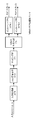
- FIG. 1 is a diagram showing a configuration of transmitting apparatus 100 in the first embodiment.
- FIG. 2 is a diagram showing a configuration of the PLP processing unit 111 in the first embodiment.
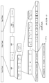
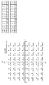
- FIG. 3 is a diagram showing a non-uniform mapping shape 64QAM (coding rate 2/5) constellation arrangement when the code length of LDPC coding is 64k mode in the first embodiment.
- FIG. 4 is a diagram illustrating a 64QAM (all coding rate) constellation arrangement with a non-uniform mapping shape when the code length of LDPC coding is 64k mode in the first embodiment.
- FIG. 5 is a diagram illustrating a configuration of the L1 information processing unit 141 according to the first embodiment.
- FIG. 6 is a diagram showing L1 information included in the PLP loop in L1-post (configurable) in the first embodiment.
- FIG. 7 is a diagram showing a configuration of receiving apparatus 200 in the first embodiment.
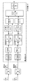
- FIG. 8 is a diagram showing a configuration of transmitting apparatus 300 in the second embodiment.
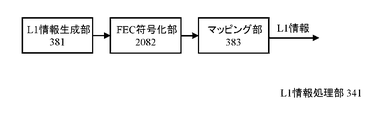
- FIG. 9 is a diagram illustrating a configuration of the L1 information processing unit 341 according to the second embodiment.
- FIG. 10 is a diagram showing L1 information related to L1-post included in L1-pre in the second embodiment.
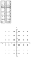
- FIG. 11 is a diagram illustrating a 64QAM (coding rate 7/15) constellation arrangement of a non-uniform mapping shape in L1-post in the second embodiment.
- FIG. 12 is a diagram showing a configuration of receiving apparatus 400 in the second embodiment.
- FIG. 12 is a diagram showing a configuration of receiving apparatus 400 in the second embodiment.
- FIG. 13 is a diagram illustrating a configuration of the L1 information processing unit 345 in a modification of the second embodiment.
- FIG. 14 is a diagram showing L1 information related to L1-post included in L1-pre in the modification of the second embodiment.
- FIG. 15 shows a non-uniform mapping shape 64QAM (coding rate 7/15) constellation arrangement in L1-post in the modification of the second embodiment.
- FIG. 16 is a diagram illustrating a configuration of receiving apparatus 450 in a modification of the second embodiment.
- FIG. 17 is a diagram illustrating a configuration of transmitting apparatus 500 in the third embodiment.
- FIG. 18 is a diagram showing a configuration of the MIMO-PLP processing unit 531 in the third embodiment.
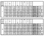
- FIG. 19 is a diagram illustrating a 64QAM (coding rate 2/5) constellation arrangement with a non-uniform mapping shape in the MIMO profile in the third embodiment.
- FIG. 20 is a diagram showing a 64QAM (all coding rate) constellation arrangement with a non-uniform mapping shape in the MIMO profile in the first embodiment.
- FIG. 21 is a diagram illustrating a configuration of the L1 information processing unit 541 according to the third embodiment.
- FIG. 22 is a diagram illustrating L1 information included in a PLP loop in L1-post (configurable) in the third embodiment.
- FIG. 23 is a diagram illustrating a configuration of receiving apparatus 600 in the third embodiment.
- FIG. 24 is a diagram showing a DVB-NGH transmission frame configuration.
- FIG. 25 is a diagram illustrating a configuration of the transmission apparatus 2000 in a conventional DVB-NGH Base profile (SISO frame).
- FIG. 26 is a diagram illustrating a configuration of the PLP processing unit 2011 in the conventional DVB-NGH system.
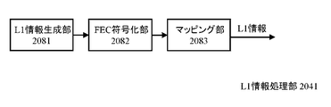
- FIG. 27 is a diagram illustrating a configuration of the L1 information processing unit 2041 in the conventional DVB-NGH system.
- FIG. 28 is a diagram showing a 64QAM constellation arrangement having a uniform mapping shape in the conventional DVB-NGH system.
- FIG. 29 is a diagram showing a 64QAM (coding rate 2/5) constellation arrangement of a non-uniform mapping shape in the conventional DVB-NGH system.
- FIG. 30 is a diagram showing a 64QAM (all coding rate) constellation arrangement of a non-uniform mapping shape in the conventional DVB-NGH system.
- FIG. 24 is a diagram showing a DVB-NGH transmission frame configuration.
- the DVB-NGH system has a concept called PLP (Physical Layer Pipe), and is characterized in that transmission parameters such as a modulation system and a coding rate can be set independently for each PLP.
- the number of PLPs is a minimum of 1 and a maximum of 255, and FIG. 24 shows a case where the number of PLPs is 10 as an example.
- the transmission frame configuration is shown below.
- the P1 symbol has 4 bits of S2 and the frame format is NGH_SISO or NGH_MISO
- information such as FFT size in the subsequent P2 symbol and data symbol is transmitted.
- the P1 symbol is ESC indicating the other frame by 4 bits of S2
- the frame format (such as NGH_MIMO) is transmitted.
- the aP1 symbol transmits information such as the FFT size in the subsequent P2 symbol and data symbol by 3 bits of S3.
- the P2 symbol includes L1 signaling information in the first half and main signal data in the remaining second half.
- the data symbol includes a continuation of the main signal data.
- the L1 signaling information transmitted by the P2 symbol is mainly configured by L1-pre information for transmitting information common to all PLPs and L1-post information for mainly transmitting information for each PLP.
- FIG. 24 shows a configuration of LC (Logical Channel) type A in which L1-post information is transmitted following L1-pre information.
- LC type B the transmission order of L1-post information is not limited to the order after L1-pre information.
- FIG. 25 is a diagram illustrating a configuration of the transmission device 2000 in the DVB-NGH Base profile (see Non-Patent Document 3).
- SISO Single Input Single Output
- the transmission apparatus 2000 includes an L1 (Layer-1) information processing unit 2041, a frame configuration unit 2021, an OFDM signal generation unit 2061, a D / A conversion unit 2091, and a frequency conversion unit 2096.
- the PLP processing unit 2011 for each PLP associates each input stream with the PLP, performs processing related to the PLP, and outputs mapping data (cell) of each PLP.
- input streams include TS (Transport Stream), service components such as audio and video included in a program with TS, and service sub-layers such as Base layer and Enhancement layer for video using SVC (Scalable Video Coding).
- service sub-layers such as Base layer and Enhancement layer for video using SVC (Scalable Video Coding).
- Examples of information source coding include H.component. H.264 and HEVC (H.265).
- the L1 information processing unit 2041 performs processing related to the L1 information and outputs mapping data of the L1 information.
- the frame configuration unit 2021 uses the mapping data of each PLP output from the PLP processing unit 2011 and the mapping data of L1 information output from the L1 information processing unit 2041 to transmit a DVB-NGH transmission frame shown in FIG. Is generated and output.
- the OFDM signal generation unit 2061 performs pilot signal addition, IFFT (Inverse Fast Fourier Transform), GI insertion, and P1 symbol insertion on the DVB-NGH transmission frame configuration output from the frame configuration unit 2021. , DVB-NGH digital baseband transmission signals are output.
- the D / A converter 2091 performs D / A conversion on the DVB-NGH digital baseband transmission signal output from the OFDM signal generator 2061 and outputs a DVB-NGH analog baseband transmission signal.
- the frequency conversion unit 2096 performs frequency conversion on the DVB-NGH analog baseband transmission signal output from the D / A conversion unit 2091 and outputs a DVB-NGH analog RF transmission signal from a transmission antenna (not shown). To do.
- the PLP processing unit 2011 includes an input processing unit 2071, an FEC (Forward Error Correction) encoding unit 2072, a mapping unit 2073, and an interleaving unit 2074.
- FEC Forward Error Correction
- the input processing unit 2071 converts the input stream into a baseband frame.
- the FEC encoder 2072 performs BCH encoding and LDPC encoding for each baseband frame, adds parity bits, and generates an FEC frame.
- the mapping unit 2073 performs mapping to the I / Q coordinates, converts it into an FEC block, and outputs each mapping data (cell).
- the interleaving unit 2074 rearranges mapping data (cell) within a TI (Time Interleaving) block including an integer number of FEC blocks.
- the L1 information processing unit 2041 includes an L1 information generation unit 2081, an FEC encoding unit 2082, and a mapping unit 2083.
- the L1 information generation unit 2081 In the L1 information processing unit 2041, the L1 information generation unit 2081 generates transmission parameters and converts them into L1-pre information and L1-post information.
- the FEC encoding unit 2082 performs BCH encoding and LDPC encoding for each L1-pre information and L1-post information, and adds a parity bit.
- the mapping unit 2083 performs mapping to the I / Q coordinates and outputs mapping data (cell).
- the DVB-T2 method adopts only QAM (Quadrature Amplitude Modulation) with a uniform mapping shape.
- the DVB-NGH system adopts not only uniform but also non-uniform mapping shape QAM.
- FIG. 28 and FIG. 29 show a 64QAM constellation arrangement with a uniform mapping shape and a 64QAM (coding rate 2/5) constellation arrangement with a non-uniform mapping shape in the DVB-NGH system, respectively.
- (a) shows a constellation layout
- (b) shows IQ coordinates.
- AWGN additive white Gaussian noise
- FIG. 30 shows IQ coordinates of a 64QAM (all coding rate) constellation arrangement with a non-uniform mapping shape in the DVB-NGH system.
- the shape of non-uniform mapping is defined for each coding rate.
- the DVB-NGH system employs only 16,200 bits (hereinafter referred to as 16k mode) for data PLP (Physical Layer Pipe) as the code length of LDPC encoding.
- the DVB-T2 system adopts not only the 16k mode but also 64,800 bits (hereinafter referred to as the 64k mode).
- the 64k mode with a long code length has higher error correction capability than the 16k mode with a short code length, and when the nonuniform mapping shape of the DVB-NGH method is applied to the 64k mode as it is, the shaping gain is increased around the required C / N ratio. It may not be possible to obtain the maximum.
- the L1 signaling information In the DVB-NGH system, only 4,320 bits (hereinafter referred to as 4k mode) are used for the L1 signaling information.
- 4k mode 4,320 bits
- the L1 signaling information not only uniform but also non-uniform mapping is adopted for the L1-post information, but the shape of the non-uniform mapping is the same as the data PLP using the 16k mode, and the required C / N There is a possibility that the shaping gain cannot be obtained to the maximum near the ratio.
- the 16k mode is used for the L1 signaling information
- the coding rate 4/9 is used for the L1-post information, which is used in the data PLP. It is one of the coding rates.
- the L1-post information is shortened or punctured when the number of information bits is small, but the error correction capability is reduced due to the small number of information bits. Therefore, when the non-uniform mapping shape of the data PLP is directly applied to the L1-post information, there is a possibility that the shaping gain cannot be obtained to the maximum in the vicinity of the required C / N ratio.
- MIMO Multiple Input Multiple Multiple Output
- MIMO is parallel transmission using a plurality of transmission / reception antennas, and it is difficult to completely eliminate the influence of inter-antenna interference. Therefore, when the same modulation scheme, coding rate, and code length as SISO are used, the required C / N The ratio becomes high. Therefore, if the shape of non-uniform mapping of SISO is applied to MIMO as it is, there is a possibility that the shaping gain cannot be obtained to the maximum near the required C / N ratio.
- the present disclosure has been made to solve the above-described problem, and provides a transmission device, a transmission method, a reception device, and a reception method that efficiently obtain a shaping gain using modulation of a non-uniform mapping shape.
- a transmission apparatus includes an error correction encoding unit that generates an error correction encoded frame by performing error correction encoding for each data block having a predetermined length, and transmits the error correction encoded frame by a predetermined number of bits.
- a mapping unit that maps to a symbol and generates an error correction coding block, and two or more types of lengths of the error correction coding frame can be selected, and the mapping unit includes the error correction code Even if the coding rate in the coding unit is the same, the first length and the second length of the error correction coding frame are mapped to different non-uniform shapes.
- the transmitting apparatus generates L1 (Layer-1) signaling information for storing transmission parameters in the transmitting apparatus according to the first disclosure, performs error correction coding on the L1 signaling information,
- a transmission frame including an L1 signaling information processing unit that maps bits by symbol, an error correction coding block output from the mapping unit, and mapping data of L1 signaling information output from the L1 signaling information processing unit
- the L1 signaling information includes the length of the error correction coded frame and the coding rate.
- the receiving apparatus is different in non-uniformity with respect to the first length and the second length of the error correction coding frame even if the coding rate of the error correction coding is the same.
- a receiving device that receives a signal mapped to a shape and transmits the signal, a demodulation unit that demodulates the transmission signal, and a length and a coding rate of an error correction coding frame from the data demodulated by the demodulation unit And a demapping unit that performs demapping by detecting the mapping of the non-uniform shape.
- a transmission apparatus includes an error correction encoding unit that generates an error correction encoded frame by performing error correction encoding for each data block having a predetermined length, and the error correction encoded frame is transmitted by a predetermined number of bits.
- a mapping unit for mapping to a symbol to generate an error correction coding block, and L1 (Layer-1) signaling information for storing transmission parameters are generated, and the L1 signaling information is error correction coded to perform L1 error correction coding.
- An L1 signaling information processing unit that generates a frame and maps the L1 error correction coding frame to a symbol by a predetermined number of bits; an error correction coding block output from the mapping unit; and the L1 signaling information processing unit Including the mapping data of the output L1 signaling information and the frame constituting the transmission frame.
- the L1 signaling information processing unit even if the coding rate in the error correction coding of the L1 signaling information is the same as the coding rate in the error correction coding unit, the mapping The mapping is performed differently from the mapping of the non-uniform shape in the part.
- the transmission device is the transmission device according to the fourth disclosure, wherein the length of the L1 error correction encoded frame and the length of the error correction encoded frame are different from each other.
- a transmission device is the transmission device according to the fourth disclosure, wherein the L1 signaling information processing unit performs a shortening process at least before performing error correction coding on the L1 signaling information, or Puncture processing is performed after error correction coding of the L1 signaling information.
- a transmission device is the transmission device according to the sixth disclosure, wherein the length of the L1 error correction encoded frame and the length of the error correction encoded frame are the same.
- the receiving apparatus maps to L1 (Layer-1) signaling information storing transmission parameters and non-uniform shapes different from each other even if the coding rate of error correction coding of the transmission stream is the same
- a receiver that receives the transmitted signal, a demodulator that demodulates the transmission signal, and an extractor that extracts the L1 signaling information and the transmission stream from the data demodulated by the demodulator
- a demapping unit that performs demapping on the extracted L1 signaling information and the extracted transmission stream based on mapping of different non-uniform shapes.
- the transmission device has a function of executing communication in at least two transmission methods among SISO (Single Input Single Output), MISO (Multiple Input Single Output), and MIMO (Multiple Input Input Multiple Output).
- An error correction encoding unit that generates an error correction encoded frame by performing error correction encoding for each data block having a predetermined length, and mapping the error correction encoded frame to a symbol by a predetermined number of bits
- a mapping unit that generates an error correction coding block, and the mapping unit is different from the transmission method even if the coding rate in the error correction coding unit is the same. Map to a uniform shape.
- the receiving apparatus has a function of executing communication in at least two transmission methods of SISO (Single Input Single Output), MISO (Multiple Input Single Output), and MIMO (Multiple Input Multiple Output).
- SISO Single Input Single Output
- MISO Multiple Input Single Output
- MIMO Multiple Input Multiple Output
- a reception device that receives signals transmitted by being mapped to different non-uniform shapes with respect to the transmission method, even if the coding rate of error correction coding is the same, and the transmission signal
- a demodulator that demodulates the transmission signal, and a demapper that performs demapping on the detected transmission method based on non-uniform shape mapping that differs for each transmission method. It has a mapping part.
- a transmission method includes: an error correction encoding step for generating an error correction encoded frame by performing error correction encoding for each data block having a predetermined length; and the error correction encoded frame for each predetermined number of bits.
- a mapping step for mapping to a symbol to generate an error correction coding block, and two or more types of lengths of the error correction coding frame can be selected, and the mapping step includes the error correction code Even if the coding rate in the coding unit is the same, the first length and the second length of the error correction coding frame are mapped to different non-uniform shapes.
- reception method for receiving a signal mapped and transmitted in a shape, wherein a demodulation step for demodulating the transmission signal, and a length and a coding rate of an error correction coding frame from data demodulated by the demodulation unit And a demapping step of performing demapping by detecting the non-uniform shape mapping.
- a transmission method includes: an error correction encoding step for generating an error correction encoded frame by performing error correction encoding for each data block having a predetermined length; and the error correction encoded frame for each predetermined number of bits.
- Mapping step for mapping to symbols to generate error correction coding blocks; L1 (Layer-1) signaling information for storing transmission parameters; generating L1 error correction coding by error correction coding of the L1 signaling information
- the L1 signaling information processing step wherein the coding rate in the error correction coding of the L1 signaling information is the same as the coding rate in the error correction coding unit.
- the mapping is performed differently from the non-uniform shape mapping in the mapping unit.
- the reception method according to the fourteenth disclosure is such that L1 (Layer-1) signaling information for storing transmission parameters and the error correction coding rate of a transmission stream are mapped to different non-uniform shapes even when the coding rate of error correction coding of the transmission stream is the same.
- the transmission method has a function of executing communication in at least two transmission methods of SISO (Single Input Single Output), MISO (Multiple Input Single Output), and MIMO (Multiple Input Multiple Output).
- An error correction encoding step for generating an error correction encoded frame by performing error correction encoding for each data block of a predetermined length, and mapping the error correction encoded frame into symbols by a predetermined number of bits
- the reception method according to the sixteenth disclosure has a function of executing communication in at least two transmission methods among SISO (Single Input Single Output), MISO (Multiple Input Single Output), and MIMO (Multiple Input Input Multiple Output). And a reception method for receiving signals transmitted by being mapped to different non-uniform shapes with respect to the transmission scheme, even if the coding rate of error correction coding is the same. And a demodulating step for demodulating the transmission signal, and a demapper for performing the demapping on the detected transmission method based on a non-uniform shape mapping different for each transmission method. Includes a mapping step.
- the transmission apparatus even if the coding rate in the error correction coding unit is the same, the first length and the second length of the error correction coded frame are different from each other. By mapping to a non-uniform shape, a shaping gain can be obtained efficiently.
- the L1 signaling information includes the length of the error correction coding frame and the coding rate, so that the coding rate in the error correction coding unit is the same. Also, different non-uniform mapping shapes can be defined for the first length and the second length of the error correction coding frame and notified to the receiver.
- the demodulation unit demodulates the transmission signal
- the demapping unit refers to the length and coding rate of the error correction coding frame
- the mapping of the non-uniform shape is performed. Is detected and demapping is performed, so that even if the coding rate of error correction coding is the same, the first length and the second length of the error correction coding frame are different from each other.
- a signal transmitted after being mapped into a uniform shape can be received.
- the shaping gain is efficiently obtained by mapping to different non-uniform shapes. be able to.
- the transmission device even when the coding rates of the L1 signaling information and the transmission stream are the same, when the lengths of the error correction coding frames are different, the non-uniform shapes that are different from each other By mapping to, a shaping gain can be obtained efficiently.
- the transmission device even if the coding rate of the L1 signaling information and the transmission stream is the same, at least the L1 signaling information is subjected to a shortening process before error correction coding, Alternatively, when puncturing is performed after error correction coding of the L1 signaling information, a shaping gain can be efficiently obtained by mapping to different non-uniform shapes.
- At least L1 signaling information is error correction encoded even if the coding rate of the transmission stream and the length of the error correction encoded frame are the same.
- the shaping gain can be efficiently obtained by mapping to different non-uniform shapes. .
- the demodulation unit demodulates the transmission signal
- the extraction unit extracts the L1 signaling information and the transmission stream
- the demapping unit extracts the L1 signaling information and the transmission stream.
- the shaping is performed by mapping to different non-uniform shapes. Gain can be obtained efficiently.
- the demodulation unit detects the transmission method from the transmission signal, demodulates the transmission signal, and at least two transmissions with respect to the transmission method in which the demapping unit is detected.
- the first length and the second length of the error correction coded frame are: By mapping to different non-uniform shapes, a shaping gain can be obtained efficiently.
- the demodulation step demodulates the transmission signal
- the demapping step refers to the length and coding rate of the error correction coding frame
- the mapping of the non-uniform shape is performed. Is detected and demapping is performed, so that even if the coding rate of the error correction code step is the same, the first length and the second length of the error correction coded frame are different from each other.
- a signal transmitted after being mapped into a uniform shape can be received.
- the shaping gain is efficiently obtained by mapping to different non-uniform shapes. be able to.
- the demodulation step demodulates the transmission signal
- the extraction step extracts the L1 signaling information and the transmission stream, and the L1 signaling information and the transmission stream from which the demapping step is extracted.
- demapping based on different non-uniform shape mapping even if the coding rate of the L1 signaling information and the transmission stream is the same, they are mapped to different non-uniform shapes and transmitted. Received signals can be received.
- the shaping is performed by mapping to different non-uniform shapes. Gain can be obtained efficiently.
- the demodulation step detects the transmission scheme from the transmission signal, demodulates the transmission signal, and at least two transmissions are performed with respect to the transmission scheme in which the demapping step is detected.
- demapping based on mapping of non-uniform shapes that are different from each other in the method, even if the coding rate of any two transmission methods of SISO, MISO, and MIMO is the same, different non-uniform shapes are obtained.
- a mapped and transmitted signal can be received.
- FIG. 1 is a diagram illustrating a configuration of the transmission device 100 according to the first embodiment of the present disclosure.
- the same components as those of the conventional transmission apparatus are denoted by the same reference numerals, and description thereof is omitted.
- a case will be described in which not only the 16k mode but also the 64k mode is used as the code length of LDPC encoding for data PLP.
- 1 has a configuration in which the PLP processing unit 2011 and the L1 information processing unit 2041 are replaced with a PLP processing unit 111 and an L1 information processing unit 141, respectively, as compared with the conventional transmission device 2000 shown in FIG. .
- the PLP processing unit 111 for each PLP associates each input stream with the PLP, performs processing related to the PLP, and outputs mapping data (cell) of each PLP.
- FIG. 2 is a diagram illustrating a configuration of the PLP processing unit 111.
- the input processing unit 2071, the FEC encoding unit 2072, and the mapping unit 2073 are replaced with the input processing unit 171, the FEC encoding unit 172, and the mapping unit 173, respectively. is there.
- the input processing unit 171 converts the input stream into a baseband frame depending on whether the code length of LDPC encoding is 16k mode or 64k mode.
- the FEC encoding unit 172 adds parity bits by performing BCH encoding and LDPC encoding for each baseband frame depending on whether the code length of LDPC encoding is 16k mode or 64k mode, and adds an FEC frame. Is generated.
- the mapping unit 173 performs mapping to the I / Q coordinates, converts it to an FEC block, and outputs each mapping data (cell).
- FIG. 3 shows a 64QAM (coding rate 2/5) constellation layout of a non-uniform mapping shape when the code length of LDPC encoding is 64k mode.
- the non-uniform mapping shape of FIG. 29 is used as in the DVB-NGH method.
- non-uniform mapping in the case of 16k mode is not used as it is, but non-uniform mapping with a coding rate 1/3 lower is used. This is because the 64k mode with a long code length has higher error correction capability and a lower required C / N ratio than the 16k mode with a short code length.
- FIG. 4 shows the I / Q coordinates of a 64QAM (all coding rate) constellation arrangement with a non-uniform mapping shape when the code length of LDPC coding in this embodiment is the 64k mode.
- the non-uniform mapping shape of FIG. 30 is used as in the DVB-NGH method.
- nonuniform mapping in the case of 16k mode is not used as it is, but nonuniform mapping with a coding rate one step lower is used.
- a non-uniform mapping is newly defined for the coding rate 1/3.
- FIG. 5 is a diagram illustrating a configuration of the L1 information processing unit 141. Compared with the conventional L1 information processing unit 2041 shown in FIG. 27, the L1 information generation unit 2081 is replaced with an L1 information generation unit 181.
- the L1 information generation unit 181 generates transmission parameters and converts them into L1-pre information and L1-post information.
- FIG. 6 shows L1 information included in the PLP loop in L1-post (configurable).
- PLP_FEC_TYPE indicates whether the code length of LDPC encoding is 16k mode or 64k mode.
- PLP_COD indicating the coding rate
- PLP_NON_UNIFFORM_CONST indicating whether the mapping is uniform or non-uniform
- PLP_MOD indicating the modulation scheme
- a shaping gain can be efficiently obtained by defining different non-uniform mapping shapes for different LDPC code lengths at the same coding rate.
- FIG. 7 is a diagram illustrating a configuration of the reception device 200 according to the first embodiment of the present disclosure.
- the receiving apparatus 200 in FIG. 7 corresponds to the transmitting apparatus 100 in FIG. 1 and reflects the function of the transmitting apparatus 100.
- the receiving apparatus 200 includes a tuner unit 205, an A / D conversion unit 208, a demodulation unit 211, a frequency deinterleave / L1 information deinterleave unit 215, a PLP deinterleave unit 221, a selection unit 231, and a demapping unit.
- Unit 232 and FEC decoding unit 233 are included in The receiving apparatus 200.
- the tuner unit 205 When an analog RF reception signal is input from the reception antenna, the tuner unit 205 selectively receives the signal of the selected frequency channel and down-converts it to a predetermined band.
- the A / D conversion unit 208 performs A / D conversion and outputs a digital reception signal.
- the demodulator 211 performs OFDM demodulation, and outputs I / Q coordinate cell data and a transmission path estimation value.
- the frequency deinterleaving / L1 information deinterleaving unit 215 performs frequency deinterleaving between the PLP cell data including the selected program data and the channel estimation value, and deinterleaves the cell data and the channel estimation value of the L1 information. Do.
- the deinterleaved cell data of L1 information and the transmission path estimation value are selected by the selection unit 231.
- the demapping unit 232 performs demapping processing
- the FEC decoding unit 233 performs LDPC decoding processing and BCH decoding processing. Thereby, the L1 information is decoded.
- the PLP deinterleaving unit 221 uses the scheduling data included in the decoded L1 information to obtain cell data and a transmission path estimation value of PLP (for example, PLP-1 shown in FIG. 1) including the program selected by the user. Extraction is performed, and rearrangement is performed in reverse to the interleaving process on the transmission side.
- the deinterleaved PLP-1 cell data and transmission path estimation value are selected by the selector 231.
- the demapping unit 232 performs demapping processing on the PLP cell data and the transmission path estimation value output from the selection unit 231, and the FEC decoding unit 233 performs LDPC decoding processing and BCH decoding processing. As a result, the PLP data is decoded.
- the demapping unit 232 When performing the demapping process, the demapping unit 232 performs PLP_FEC_TYPE and PLP_COD shown in FIG. 6 with respect to a PLP (for example, PLP-1 shown in FIG. 1) selected by the user from the decoded L1 information. , PLP_NON_UNIFORM_CONST, PLP_MOD. Accordingly, even when the transmission apparatus 100 of FIG. 1 defines different non-uniform mapping shapes for different LDPC code lengths at the same coding rate, the demapping unit 232 can detect the mapping shape, and the detected mapping Demapping processing based on the shape is possible.
- PLP for example, PLP-1 shown in FIG. 1
- the integrated circuit 240 may be configured to include components other than the tuner unit 205 in the receiving apparatus 200 of FIG.
- a receiving device that receives transmission signals in which different non-uniform mapping shapes are defined for different LDPC code lengths at the same coding rate, and reception Methods, integrated circuits, and programs can be provided.
- FIG. 8 is a diagram illustrating a configuration of the transmission device 300 according to the second embodiment of the present disclosure.
- the same components as those of the conventional transmission device and the transmission device of Embodiment 1 are denoted by the same reference numerals, and description thereof is omitted.
- the code length of LDPC encoding for L1 information is the 4k mode as in the DVB-NGH system.
- FIG. 9 is a diagram illustrating a configuration of the L1 information processing unit 341. Compared with the conventional L1 information processing unit 2041 shown in FIG. 27, the L1 information generation unit 2081 and the mapping unit 2083 are replaced with an L1 information generation unit 381 and a mapping unit 383, respectively.
- the L1 information generation unit 381 generates transmission parameters and converts them into L1-pre information and L1-post information.
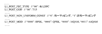
- FIG. 10 shows L1 information related to L1-post included in L1-pre.
- L1_POST_FEC_TYPE indicates that the code length of LDPC encoding is 4k mode.
- L1_POST_COD indicating the coding rate
- L1_POST_NON_UNIFFORM_CONST indicating whether the mapping is uniform or non-uniform
- L1_POST_MOD indicating the modulation scheme are included.
- mapping unit 383 performs mapping to the I / Q coordinates, converts them into FEC blocks, and outputs each mapping data (cell).
- FIG. 11 shows a 64QAM (coding rate 7/15) constellation layout diagram of non-uniform mapping shape in L1-post.
- the non-uniform mapping of the data PLP (16k mode) is not used as it is, but the non-uniform mapping with a high coding rate of 3/5 is used. Yes.
- L1-post takes into account that a reduction in error correction capability due to the small number of information bits occurs, so that the coding rate is not one step higher than 8/15 but two steps higher coding rate 3/5.
- Non-uniform mapping is used.
- FIG. 12 is a diagram illustrating a configuration of the reception device 400 according to the second embodiment of the present disclosure.
- a receiving apparatus 400 in FIG. 12 corresponds to the transmitting apparatus 300 in FIG. 8 and reflects the function of the transmitting apparatus 300.
- the same components as those of receiving apparatus 200 of Embodiment 1 are denoted by the same reference numerals, and description thereof is omitted.
- the frequency deinterleave / L1 information deinterleave unit 215 deinterleaves the L1 information cell data and the transmission path estimation value, which are selected by the selection unit 231.
- the demapping unit 432 performs L1-pre demapping processing
- the FEC decoding unit 233 performs LDPC decoding processing and BCH decoding processing. As a result, the L1-pre information is decoded.
- the demapping unit 432 refers to L1_POST_FEC_TYPE, L1_POST_COD, L1_POST_NON_UNIFORM_CONST, and L1_POST_MOD shown in FIG. 10 from the decoded L1-pre information when performing the demapping process of L1-post.
- demapping section 432 can perform L1- Mapping shapes can be detected for both post and data PLP, and demapping processing based on the detected mapping shapes can be performed.
- the FEC decoding unit 233 performs LDPC decoding processing and BCH decoding processing of L1-post subjected to demapping processing. As a result, the L1-post information is decoded.
- the operation for the data PLP after the PLP deinterleave unit 221 is the same as that of the first embodiment.
- the integrated circuit 440 may be configured to include components other than the tuner unit 205 in the receiving apparatus 400 of FIG.
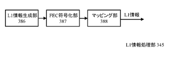
- L1 information processing unit 341 illustrated in FIG. 9 may be replaced with the L1 information processing unit 345 illustrated in FIG.
- this modification a case will be described in which the same 16k mode as that of data PLP is used as the code length of LDPC encoding for L1 information.
- L1 information processing unit 341 shown in FIG. 9 in that the L1 information generation unit 381, the FEC encoding unit 2087, and the mapping unit 383 are replaced with the L1 information generation unit 386 and the FEC encoding unit. 387 and the mapping unit 388, respectively.
- the L1 information generation unit 386 generates transmission parameters and converts them into L1-pre information and L1-post information.
- FIG. 14 shows L1 information related to L1-post included in L1-pre.
- L1_POST_FEC_TYPE indicates that the code length of LDPC encoding is 16k mode. Other than that, it is the same as FIG.
- the FEC encoding unit 387 adds a parity bit by performing BCH encoding and LDPC encoding for each of L1-pre information and L1-post information using the 16k mode. .
- the mapping unit 388 performs mapping to the I / Q coordinates, converts it to an FEC block, and outputs each mapping data (cell).
- FIG. 15 shows a 64QAM (coding rate 7/15) constellation layout diagram of non-uniform mapping shape in L1-post.
- L1-post (16k mode) non-uniform mapping of data PLP (16k mode) is not used as it is, but non-uniform mapping with a higher coding rate of 8/15 is used. ing. This is because even if the code length is the same, L1-post takes into consideration that the error correction capability is reduced due to the small number of information bits.
- FIG. 16 shows the configuration of receiving apparatus 450 when the above-described L1 information processing unit 345 shown in FIG. 13 is applied.
- the receiving device 450 illustrated in FIG. 16 has a configuration in which the demapping unit 432 and the FEC decoding unit 233 are replaced with a demapping unit 482 and an FEC decoding unit 483, respectively, as compared with the receiving device 400 illustrated in FIG.
- the FEC decoding unit 483 performs demapping L1-pre LDPC decoding processing and BCH decoding processing using the 16k mode. As a result, the L1-pre information is decoded.
- the demapping unit 482 refers to the L1_POST_FEC_TYPE, L1_POST_COD, L1_POST_NON_UNIFORM_CONST, and L1_POST_MOD shown in FIG. 14 from the decoded L1-pre information when performing the L1-post demapping process.
- the demapping unit 482 can perform the same operation on the L1-post and the data PLP.
- the mapping shape can be detected for both of them, and the demapping process based on the detected mapping shape can be performed.
- the FEC decoding unit 483 performs L1-post LDPC decoding processing and BCH decoding processing on which demapping processing has been performed. As a result, the L1-post information is decoded.
- the operation for the data PLP after the PLP deinterleaver 221 is the same as that of the receiving apparatus 400 in FIG.
- the integrated circuit 441 may be configured to include components other than the tuner unit 205 in the receiving device 450 of FIG.
- FIG. 17 is a diagram illustrating a configuration of the transmission device 500 according to the third embodiment of the present disclosure.
- the same components as those of the conventional transmitter and the transmitters of Embodiments 1 and 2 are denoted by the same reference numerals, and the description thereof is omitted.
- this embodiment a case of a MIMO profile in the DVB-NGH system will be described.
- the transmission apparatus 500 includes an OFDM signal generation unit 2061, a D / A conversion unit 2091, and a frequency conversion unit 2096 for each transmission antenna (Tx-1, Tx-2).
- FIG. 18 is a diagram illustrating a configuration of the MIMO-PLP processing unit 531.
- the mapping unit 2073 is replaced with a mapping unit 573, a MIMO encoding unit 576 is added, and an interleaving unit 2074 for each of two transmission antennas is provided.
- mapping unit 573 performs mapping to the I / Q coordinates, converts it to an FEC block, and outputs each mapping data (cell).
- FIG. 19 shows a 64QAM (coding rate 2/5) constellation layout of a non-uniform mapping shape in the MIMO profile.
- 64QAM coding rate 2/5) constellation layout of a non-uniform mapping shape in the MIMO profile.
- FIG. 19 shows a 64QAM (coding rate 2/5) constellation layout of a non-uniform mapping shape in the MIMO profile.
- non-uniform mapping in the case of the SISO frame of the Base profile is not used as it is, but non-uniform mapping with a higher coding rate of 7/15 is used. This is because MIMO is parallel transmission using a plurality of transmission / reception antennas, and it is difficult to completely eliminate the influence of inter-antenna interference, so that the required C / N ratio increases.
- FIG. 20 shows the I / Q coordinates of a 64QAM (all coding rate) constellation arrangement with a non-uniform mapping shape in the MIMO profile in the present embodiment.
- non-uniform mapping in the case of the SISO frame of the Base profile is not used as it is, but non-uniform mapping with a higher coding rate is used for each. Note that non-uniform mapping is newly defined for the coding rate 11/15.
- the MIMO encoding unit 576 performs MIMO encoding on the mapping data (cell) output from the mapping unit 573.
- the interleave unit 2074 for each of the two transmission antennas rearranges the mapping data (cell) in the TI block including an integer number of FEC blocks.
- FIG. 21 is a diagram showing a configuration of the L1 information processing unit 541.
- the L1 information generation unit 2081, the FEC encoding unit 2082, and the mapping unit 2083 are replaced with an L1 information generation unit 581, an FEC encoding unit 387, and a mapping unit 583, respectively.
- a MIMO encoding unit 576 is added.
- the L1 information generation unit 581 generates transmission parameters and converts them into L1-pre information and L1-post information.
- FIG. 22 shows L1 information included in the PLP loop in L1-post (configurable).
- PLP_FEC_TYPE indicates that the code length of LDPC encoding is 16k mode.
- PLP_COD indicating the coding rate
- PLP_NON_UNIFFORM_CONST indicating whether the mapping is uniform or non-uniform
- PLP_MOD indicating the modulation scheme are included.
- the P1 symbol indicates that the format of this frame is NGH_MIMO.
- L1 information related to L1-post included in L1-pre is the same as that in FIG. 14 in the modification of the second embodiment.
- L1 information related to L1-post included in L1-pre is the same as that in FIG. 14 in the modification of the second embodiment.
- the operation of the FEC encoding unit 387 is the same as the operation of the L1 information processing unit 345 in FIG. 13 in the modification of the second embodiment.
- the mapping unit 583 performs mapping to the I / Q coordinates, converts it to an FEC block, and outputs each mapping data (cell).
- the non-uniform mapping shape 64QAM (coding rate 7/15) constellation arrangement in L1-post is the same as FIG. 11 in the second embodiment.
- L1-post MIMO
- non-uniform mapping of data PLP SISO
- L1-post takes into account that a reduction in error correction capability due to the small number of information bits occurs, so that the coding rate is not one step higher than 8/15 but two steps higher coding rate 3/5.
- Non-uniform mapping is used.
- the MIMO encoding unit 576 performs MIMO encoding on the mapping data (cell) output from the mapping unit 583.
- the frame configuration unit 521 includes mapping data of each PLP for the two transmission antennas (Tx ⁇ 1, Tx ⁇ 2) output from the MIMO-PLP processing unit 531 and the L1 information processing unit 541. 24 is used to generate and output a DVB-NGH transmission frame shown in FIG. 24 using the mapping data of the L1 information for the two transmission antennas (Tx-1, Tx-2) output from.
- the OFDM signal generation unit 2061 for each of the two transmission antennas adds a pilot signal, inserts IFFT, GI, P1 symbol and aP1 symbol to the DVB-NGH transmission frame configuration output from the frame configuration unit 521, respectively. Is inserted and a digital baseband transmission signal is output.
- the D / A conversion unit 2091 for each of the two transmission antennas performs D / A conversion on the digital baseband transmission signal output from the OFDM signal generation unit 2061 and outputs an analog baseband transmission signal.
- the frequency conversion unit 2096 for each of the two transmission antennas performs frequency conversion on the analog baseband transmission signal output from the D / A conversion unit 2091, and outputs an analog RF transmission signal from a transmission antenna (not shown).
- FIG. 23 is a diagram illustrating a configuration of the reception device 600 according to the third embodiment of the present disclosure.
- a receiving device 600 in FIG. 23 corresponds to the transmitting device 500 in FIG. 17 and reflects the function of the transmitting device 500.
- the same components as those of the receiving apparatuses of Embodiments 1 and 2 are denoted by the same reference numerals, and description thereof is omitted.
- the receiving apparatus 200 includes a tuner unit 205, an A / D conversion unit 208, a demodulation unit 211, a frequency deinterleave / L1 information deinterleave unit 215, and a PLP deinterleave unit for each reception antenna (Rx-1, Rx-2). 221 and a selection unit 231.
- the operation of the receiving apparatus 600 will be described.
- an analog RF reception signal is input from one reception antenna Rx-1, a tuner unit 205-1, an A / D conversion unit 208-1, a demodulation unit 211-1, a frequency deinterleave / L1 information deinterleave unit 215- 1.
- the PLP deinterleaving unit 221-1 and the selection unit 231-1 perform the same operation as the receiving apparatus 450 in the modification of the second embodiment.
- the PLP deinterleaving unit 221-2 and the selection unit 231-2 perform the same operation as the receiving apparatus 450 in the modification of the second embodiment.
- the MIMO demapping unit 632 performs L1-pre demapping processing, and the FEC decoding unit 483 performs LDPC decoding processing and BCH decoding processing. As a result, the L1-pre information is decoded.
- the MIMO demapping unit 632 refers to the L1_POST_FEC_TYPE, L1_POST_COD, L1_POST_NON_UNIFORM_CONST, and L1_POST_MOD shown in FIG. 14 from the decoded L1-pre information when performing the L1-post demapping process. It recognizes that the format of this frame is NGH_MIMO. Accordingly, even when L1-Post (MIMO) has the same coding rate and the same LDPC code length as SISO, even when transmitting apparatus 500 of FIG.
- mapping shape can be detected for L1-post (MIMO), and a MIMO demapping process based on the detected mapping shape can be performed.
- the FEC decoding unit 483 performs L1-post LDPC decoding processing and BCH decoding processing subjected to the MIMO demapping processing. As a result, the L1-post information is decoded.
- the MIMO demapping unit 632 performs a MIMO demapping process on the PLP cell data and transmission path estimation values output from the two selection units (231-1, 231-2), and the FEC decoding unit 483 performs LDPC decoding. Processing and BCH decoding processing. As a result, the PLP data is decoded.
- the MIMO demapping unit 632 When the MIMO demapping unit 632 performs the demapping process, the PLP (for example, PLP-1 shown in FIG. 1) including the program selected by the user from the decoded L1-Post information is shown in FIG. Reference is made to PLP_FEC_TYPE, PLP_COD, PLP_NON_UNIFORM_CONST, and PLP_MOD, and it is recognized from the received P1 symbol that the format of this frame is NGH_MIMO. Accordingly, when data PLP (MIMO) has the same coding rate and the same LDPC code length as data PLP (SISO), transmission apparatus 500 in FIG. 17 differs for different LDPC code lengths at the same coding rate. Even when the non-uniform mapping shape is defined, the MIMO demapping unit 632 can detect the mapping shape for the data PLP (MIMO), and can perform the MIMO demapping process based on the detected mapping shape.
- PLP for example, PLP-1 shown in FIG. 1
- the integrated circuit 640 may be configured to include components other than the tuner unit 205 in the receiving apparatus 600 of FIG.
- the present disclosure is not limited to the contents described in the above embodiment, and can be implemented in any form for achieving the purpose of the present disclosure and related or incidental purposes. .
- Embodiments 1 to 3 may be implemented in any combination.
- Embodiments 1 to 3 the description has been made based on the DVB-NGH system.
- the present invention is not limited to this, and can be applied to transmission systems other than the DVB-NGH system.
- Embodiments 1 to 3 the number of input streams and the number of PLPs are two, but this is not restrictive.
- the modulation scheme to which the non-uniform mapping shape is applied is 64QAM, but the present invention is not limited to this and can be applied to other modulation schemes.
- the FEC encoding method is a combination of BCH encoding and LDPC encoding, but is not limited thereto.
- the I coordinate and the Q coordinate of the constellation arrangement are set to the same pattern. Different patterns may be used.
- non-uniform mapping of a code rate that is one step lower for one code length is applied to different code rates for the other code length for different LDPC code lengths at the same code rate.
- the present invention is not limited to this, and non-uniform mapping shapes may be made different for different LDPC code lengths at the same coding rate by other methods.
- Embodiment 2 when L1 information has the same coding rate as data PLP and a different LDPC code length, non-uniform mapping of the data PLP at a two-step higher coding rate is performed, and the coding rate of L1 information Applied to.
- the present invention is not limited to this, and the non-uniform mapping shapes may be different from each other for the L1 information and the data PLP by other methods.
- Embodiment 3 when data PLP (MIMO) has the same coding rate and the same LDPC code length as data PLP (SISO), non-uniform coding rate of data PLP (SISO) is one step higher Mapping was applied to the coding rate of data PLP (MIMO).
- the present invention is not limited to this, and the non-uniform mapping shapes may be different from each other for the data PLP (MIMO) and the data PLP (SISO) by other methods.
- Embodiment 3 when the L1 information (MIMO) has the same coding rate and the same LDPC code length as the L1 information (SISO), the coding rate non-uniformity of the L1 information (SISO) is two steps higher. Mapping was applied to the coding rate of L1 information (MIMO). However, the present invention is not limited to this, and the non-uniform mapping shapes may be made different for the L1 information (MIMO) and the L1 information (SISO) by other methods.
- the above embodiment may relate to mounting using hardware and software.
- the above-described embodiments may be implemented or executed using a computing device (processor).
- the computing device or processor is, for example, a main processor / general processor (DSP), a digital signal processor (DSP), an ASIC (application specific integrated circuit), an FPGA (field programmable gate array), other programmable logic devices, etc. It may be.
- the above embodiments may be executed or realized by combining these devices.
- the above embodiments may be realized by a mechanism of a software module that is executed by a processor or directly by hardware.
- a combination of software modules and hardware implementation is also possible.
- the software modules may be stored on various types of computer readable storage media, such as RAM, EPROM, EEPROM, flash memory, registers, hard disk, CD-ROM, DVD, etc.
- the transmission device, the transmission method, the reception device, the reception method, the integrated circuit, and the program according to the present disclosure can be applied particularly to a transmission method using a non-uniform mapping shape modulation.
Landscapes
- Engineering & Computer Science (AREA)
- Signal Processing (AREA)
- Computer Networks & Wireless Communication (AREA)
- Physics & Mathematics (AREA)
- Probability & Statistics with Applications (AREA)
- Theoretical Computer Science (AREA)
- Quality & Reliability (AREA)
- Detection And Prevention Of Errors In Transmission (AREA)
- Burglar Alarm Systems (AREA)
- Radar Systems Or Details Thereof (AREA)
- Multimedia (AREA)
Abstract
Description
図24は、DVB―NGH方式の伝送フレーム構成を示す図である。DVB―NGH方式はPLP(Physical Layer Pipe)と呼ばれる概念を有し、PLP毎に独立に変調方式、符号化率などの伝送パラメータを設定できることが特徴の一つである。PLPの数は最小1、最大255であり、図24は例として、PLPの数が10の場合を示している。
フレーム群基本ブロック = N_F フレーム(N_F = 1~255)
フレーム = P1シンボル + aP1シンボル+ P2シンボル + データシンボル
P1シンボル = 1 シンボル
aP1シンボル = 0~1 シンボル
P2シンボル = N_P2 シンボル(N_P2はFFTサイズにより一意)
データシンボル = L_data シンボル(L_dataは可変、上限と下限あり)
P1シンボルはFFTサイズ1k、GI(Guard Interval)=1/2で送信される。P1シンボルはS1の3ビットにより、そのP1シンボルから開始するフレームのフォーマット(NGH_SISO、NGH_MISO、それ以外を示すESCなど)を送信する。
前述の通り、DVB―NGH方式においては符号化率毎に非均一マッピングの形状を定義している。DVB―NGH方式はLDPC符号化の符号長として、データPLP(Physical Layer Pipe)に対しては16,200bit(以降、16kモードと呼ぶ)のみを採用している。一方DVB―T2方式は16kモードだけでなく、64,800bit(以降、64kモードと呼ぶ)も採用している。符号長の長い64kモードは、符号長の短い16kモードより誤り訂正能力が高く、DVB―NGH方式の非均一マッピングの形状をそのまま64kモードに適用した場合、所要C/N比付近でシェーピング利得を最大限得られない可能性がある。
第1の開示に係る送信装置は、所定長のデータブロック毎に、誤り訂正符号化して誤り訂正符号化フレームを生成する誤り訂正符号化部と、前記誤り訂正符号化フレームを所定数のビットずつシンボルにマッピングして、誤り訂正符号化ブロックを生成するマッピング部と、を有し、前記誤り訂正符号化フレームの長さは2種類以上が選択可能であり、前記マッピング部は、前記誤り訂正符号化部における符号化率が同一であっても、前記誤り訂正符号化フレームの第1の長さと第2の長さに対して、互いに異なる非均一な形状にマッピングする。
<送信装置及び送信方法>
図1は、本開示の実施の形態1における送信装置100の構成を示す図である。従来の送信装置と同じ構成要素は、同じ符号を用い、説明を省略する。本実施の形態においては、データPLPに対するLDPC符号化の符号長として、16kモードだけでなく、64kモードも用いる場合に関して説明する。
図7は、本開示の実施の形態1における受信装置200の構成を示す図である。図7の受信装置200は、図1の送信装置100に対応し、送信装置100の機能を反映するものである。
<送信装置及び送信方法>
図8は、本開示の実施の形態2における送信装置300の構成を示す図である。従来の送信装置、及び実施の形態1の送信装置と同じ構成要素は、同じ符号を用い、説明を省略する。本実施の形態においては、L1情報に対するLDPC符号化の符号長がDVB-NGH方式と同じく4kモードの場合に関して説明する。
図12は、本開示の実施の形態2における受信装置400の構成を示す図である。図12の受信装置400は、図8の送信装置300に対応し、送信装置300の機能を反映するものである。実施の形態1の受信装置200と同じ構成要素は、同じ符号を用い、説明を省略する。
なお、図9に示すL1情報処理部341を図13に示すL1情報処理部345に置き換えてもよい。本変形例においては、L1情報に対するLDPC符号化の符号長としてデータPLPと同じ16kモードを用いる場合に関して説明する。
以上の図13に示すL1情報処理部345が適用された場合に対する受信装置450の構成を図16に示す。図16に示す受信装置450は図12に示す受信装置400と比較して、デマッピング部432及びFEC復号化部233をデマッピング部482及びFEC復号化部483にそれぞれ置き換えた構成である。
<送信装置及び送信方法>
図17は、本開示の実施の形態3における送信装置500の構成を示す図である。従来の送信装置、及び実施の形態1~2の送信装置と同じ構成要素は、同じ符号を用い、説明を省略する。本実施の形態においては、DVB―NGH方式におけるMIMOプロファイルの場合に関して説明する。
図23は、本開示の実施の形態3における受信装置600の構成を示す図である。図23の受信装置600は、図17の送信装置500に対応し、送信装置500の機能を反映するものである。実施の形態1~2の受信装置と同じ構成要素は、同じ符号を用い、説明を省略する。
本開示は上記の実施の形態で説明した内容に限定されず、本開示の目的とそれに関連又は付随する目的を達成するためのいかなる形態においても実施可能であり、例えば、以下であってもよい。
111,2011 PLP処理部
141,341,345,541,2041 L1情報処理部
171,2071 入力処理部
172,387,2072,2082 FEC符号化部
173,383,388,573,583,2073,2083 マッピング部
181,381,386,581,2081 L1情報生成部
200,400,450,600 受信装置
205 チューナ部
208 A/D変換部
211 復調部
215 周波数デインターリーブ・L1情報デインターリーブ部
221 PLP用デインターリーブ部
231 選択部
232,432,482 デマッピング部
233,483 FEC復号化部
240,440,441,640 集積回路
521,2021 フレーム構成部
531 MIMO-PLP処理部
576 MIMO符号化部
632,235,432,434 MIMOデマッピング部
2061 OFDM信号生成部
2074 インターリーブ部
2091 D/A変換部
2096 周波数変換部
Claims (16)
- 所定長のデータブロック毎に、誤り訂正符号化して誤り訂正符号化フレームを生成する誤り訂正符号化部と、
前記誤り訂正符号化フレームを所定数のビットずつシンボルにマッピングして、誤り訂正符号化ブロックを生成するマッピング部と、を有し、
前記誤り訂正符号化フレームの長さは2種類以上が選択可能であり、
前記マッピング部は、前記誤り訂正符号化部における符号化率が同一であっても、前記誤り訂正符号化フレームの第1の長さと第2の長さに対して、互いに異なる非均一な形状にマッピングする
ことを特徴とする送信装置。 - 伝送パラメータを格納するL1(Layer-1)シグナリング情報を生成し、前記L1シグナリング情報を誤り訂正符号化し、所定数のビットずつシンボルにマッピングするL1シグナリング情報処理部と、
前記マッピング部から出力される誤り訂正符号化ブロックと、前記L1シグナリング情報処理部から出力されるL1シグナリング情報のマッピングデータとを含んで送信フレームを構成するフレーム構成部と、を更に有し、
前記L1シグナリング情報として、前記誤り訂正符号化フレームの長さと前記符号化率を含む
ことを特徴とする請求項1に記載の送信装置。 - 誤り訂正符号化の符号化率が同一であっても、誤り訂正符号化フレームの第1の長さと第2の長さに対して、互いに異なる非均一な形状にマッピングされて送信された信号を受信する受信装置であって、
前記送信信号の復調を行う復調部と、
前記復調部で復調されたデータから、誤り訂正符号化フレームの長さと符号化率を参照し、前記非均一な形状のマッピングを検出して、デマッピングを行うデマッピング部と、を有する
ことを特徴とする受信装置。 - 所定長のデータブロック毎に、誤り訂正符号化して誤り訂正符号化フレームを生成する誤り訂正符号化部と、
前記誤り訂正符号化フレームを所定数のビットずつシンボルにマッピングして、誤り訂正符号化ブロックを生成するマッピング部と、
伝送パラメータを格納するL1(Layer-1)シグナリング情報を生成し、前記L1シグナリング情報を誤り訂正符号化してL1誤り訂正符号化フレームを生成し、前記L1誤り訂正符号化フレームを所定数のビットずつシンボルにマッピングするL1シグナリング情報処理部と、
前記マッピング部から出力される誤り訂正符号化ブロックと、前記L1シグナリング情報処理部から出力されるL1シグナリング情報のマッピングデータとを含んで送信フレームを構成するフレーム構成部と、を有し、
前記L1シグナリング情報処理部は、前記L1シグナリング情報の誤り訂正符号化における符号化率が前記誤り訂正符号化部における符号化率と同一であっても、前記マッピング部における非均一な形状のマッピングと異ならせてマッピングを行う
ことを特徴とする送信装置。 - 前記L1誤り訂正符号化フレームの長さと前記誤り訂正符号化フレームの長さが互いに異なる
ことを特徴とする請求項4に記載の送信装置。 - 前記L1シグナリング情報処理部は、少なくとも前記L1シグナリング情報を誤り訂正符号化する前に短縮化処理を行うか、または前記L1シグナリング情報を誤り訂正符号化した後にパンクチャ処理を行う
ことを特徴とする請求項4に記載の送信装置。 - 前記L1誤り訂正符号化フレームの長さと前記誤り訂正符号化フレームの長さが同一である
ことを特徴とする請求項6に記載の送信装置。 - 伝送パラメータを格納するL1(Layer-1)シグナリング情報と送信ストリームの誤り訂正符号化の符号化率が同一であっても、互いに異なる非均一な形状にマッピングされて送信された信号を受信する受信装置であって、
前記送信信号の復調を行う復調部と、
前記復調部で復調されたデータから、前記L1シグナリング情報と前記送信ストリームを抽出する抽出部と、
前記抽出されたL1シグナリング情報と前記抽出された送信ストリームに対して、互いに異なる非均一な形状のマッピングに基づき、デマッピングを行うデマッピング部と、を有する
ことを特徴とする受信装置。 - SISO(Single Input Single Output)及びMISO(Multiple Input Single Output)及びMIMO(Multiple Input Multiple Output)の内、少なくとも2つでの伝送方式で通信を実行する機能を有する送信装置であって、
所定長のデータブロック毎に、誤り訂正符号化して誤り訂正符号化フレームを生成する誤り訂正符号化部と、
前記誤り訂正符号化フレームを所定数のビットずつシンボルにマッピングして、誤り訂正符号化ブロックを生成するマッピング部と、を有し、
前記マッピング部は、前記誤り訂正符号化部における符号化率が同一であっても、前記伝送方式に対して互いに異なる非均一な形状にマッピングする
ことを特徴とする送信装置。 - SISO(Single Input Single Output)及びMISO(Multiple Input Single Output)及びMIMO(Multiple Input Multiple Output)の内、少なくとも2つでの伝送方式で通信を実行する機能を有し、誤り訂正符号化の符号化率が同一であっても、前記伝送方式に対して互いに異なる非均一な形状にマッピングされて送信された信号を受信する受信装置であって、
前記送信信号から前記伝送方式を検出して、前記送信信号の復調を行う復調部と、
前記検出された伝送方式に対して、少なくとも2つの伝送方式で互いに異なる非均一な形状のマッピングに基づき、デマッピングを行うデマッピング部と、を有する
ことを特徴とする受信装置。 - 所定長のデータブロック毎に、誤り訂正符号化して誤り訂正符号化フレームを生成する誤り訂正符号化ステップと、
前記誤り訂正符号化フレームを所定数のビットずつシンボルにマッピングして、誤り訂正符号化ブロックを生成するマッピングステップと、を有し、
前記誤り訂正符号化フレームの長さは2種類以上が選択可能であり、
前記マッピングステップは、前記誤り訂正符号化ステップにおける符号化率が同一であっても、前記誤り訂正符号化フレームの第1の長さと第2の長さに対して、互いに異なる非均一な形状にマッピングする
ことを特徴とする送信方法。 - 誤り訂正符号化の符号化率が同一であっても、誤り訂正符号化フレームの第1の長さと第2の長さに対して、互いに異なる非均一な形状にマッピングされて送信された信号を受信する受信方法であって、
前記送信信号の復調を行う復調ステップと、
前記復調部で復調されたデータから、誤り訂正符号化フレームの長さと符号化率を復号し、前記非均一な形状のマッピングを検出して、デマッピングを行うデマッピングステップと、を含む
ことを特徴とする受信方法。 - 所定長のデータブロック毎に、誤り訂正符号化して誤り訂正符号化フレームを生成する誤り訂正符号化ステップと、
前記誤り訂正符号化フレームを所定数のビットずつシンボルにマッピングして、誤り訂正符号化ブロックを生成するマッピングステップと、
伝送パラメータを格納するL1(Layer-1)シグナリング情報を生成し、前記L1シグナリング情報を誤り訂正符号化してL1誤り訂正符号化フレームを生成し、前記L1誤り訂正符号化フレームを所定数のビットずつシンボルにマッピングするL1シグナリング情報処理ステップと、
前記マッピング部から出力される誤り訂正符号化ブロックと、前記L1シグナリング情報処理部から出力されるL1シグナリング情報のマッピングデータとを含んで送信フレームを構成するフレーム構成ステップと、を含み、
前記L1シグナリング情報処理ステップは、前記L1シグナリング情報の誤り訂正符号化における符号化率が前記誤り訂正符号化部における符号化率と同一であっても、前記マッピング部における非均一な形状のマッピングと異ならせてマッピングを行う
ことを特徴とする送信方法。 - 伝送パラメータを格納するL1(Layer-1)シグナリング情報と送信ストリームの誤り訂正符号化の符号化率が同一であっても、互いに異なる非均一な形状にマッピングされて送信された信号を受信する受信方法であって、
前記送信信号の復調を行う復調ステップと、
前記復調部で復調されたデータから、前記L1シグナリング情報と前記送信ストリームを抽出する抽出ステップと、
前記抽出されたL1シグナリング情報と前記抽出された送信ストリームに対して、互いに異なる非均一な形状のマッピングに基づき、デマッピングを行うデマッピングステップと、を含む
ことを特徴とする受信方法。 - SISO(Single Input Single Output)及びMISO(Multiple Input Single Output)及びMIMO(Multiple Input Multiple Output)の内、少なくとも2つでの伝送方式で通信を実行する機能を有する送信方法であって、
所定長のデータブロック毎に、誤り訂正符号化して誤り訂正符号化フレームを生成する誤り訂正符号化ステップと、
前記誤り訂正符号化フレームを所定数のビットずつシンボルにマッピングして、誤り訂正符号化ブロックを生成するマッピングステップと、を含み、
前記マッピングステップは、前記誤り訂正符号化部における符号化率が同一であっても、前記伝送方式に対して互いに異なる非均一な形状にマッピングする
ことを特徴とする送信方法。 - SISO(Single Input Single Output)及びMISO(Multiple Input Single Output)及びMIMO(Multiple Input Multiple Output)の内、少なくとも2つでの伝送方式で通信を実行する機能を有し、誤り訂正符号化の符号化率が同一であっても、前記伝送方式に対して互いに異なる非均一な形状にマッピングされて送信された信号を受信する受信方法であって、
前記送信信号から前記伝送方式を検出して、前記送信信号の復調を行う復調ステップと、
前記検出された伝送方式に対して、少なくとも2つの伝送方式で互いに異なる非均一な形状のマッピングに基づき、デマッピングを行うデマッピングステップと、を含む
ことを特徴とする受信方法。
Priority Applications (14)
| Application Number | Priority Date | Filing Date | Title |
|---|---|---|---|
| KR1020217014653A KR102441777B1 (ko) | 2014-01-31 | 2015-01-26 | 송신 장치, 송신 방법, 수신 장치, 및 수신 방법 |
| KR1020207014032A KR102149429B1 (ko) | 2014-01-31 | 2015-01-26 | 송신 장치, 송신 방법, 수신 장치, 및 수신 방법 |
| KR1020227030336A KR102496335B1 (ko) | 2014-01-31 | 2015-01-26 | 송신 장치, 송신 방법, 수신 장치, 및 수신 방법 |
| KR1020207022705A KR102255015B1 (ko) | 2014-01-31 | 2015-01-26 | 송신 장치, 송신 방법, 수신 장치, 및 수신 방법 |
| CN201580002916.3A CN105794134B (zh) | 2014-01-31 | 2015-01-26 | 发送方法、接收方法、发送装置及接收装置 |
| JP2015559816A JP6462593B2 (ja) | 2014-01-31 | 2015-01-26 | 送信装置、送信方法、受信装置、受信方法 |
| KR1020167014884A KR102114362B1 (ko) | 2014-01-31 | 2015-01-26 | 송신 장치, 송신 방법, 수신 장치, 및 수신 방법 |
| KR1020237003620A KR20230021182A (ko) | 2014-01-31 | 2015-01-26 | 송신 장치, 송신 방법, 수신 장치, 및 수신 방법 |
| EP15743665.0A EP3101831B1 (en) | 2014-01-31 | 2015-01-26 | Transmission device, transmission method, reception device, and reception method |
| US15/206,270 US10284333B2 (en) | 2014-01-31 | 2016-07-10 | Transmission device, transmission method, reception device, and reception method |
| US16/353,296 US10756845B2 (en) | 2014-01-31 | 2019-03-14 | Transmission device, transmission method, reception device, and reception method |
| US16/932,968 US11239943B2 (en) | 2014-01-31 | 2020-07-20 | Transmission device, transmission method, reception device, and reception method |
| US17/556,256 US11671199B2 (en) | 2014-01-31 | 2021-12-20 | Transmission device, transmission method, reception device, and reception method |
| US18/137,716 US11973592B2 (en) | 2014-01-31 | 2023-04-21 | Transmission device, transmission method, reception device, and reception method |
Applications Claiming Priority (2)
| Application Number | Priority Date | Filing Date | Title |
|---|---|---|---|
| JP2014016785 | 2014-01-31 | ||
| JP2014-016785 | 2014-01-31 |
Related Child Applications (1)
| Application Number | Title | Priority Date | Filing Date |
|---|---|---|---|
| US15/206,270 Continuation US10284333B2 (en) | 2014-01-31 | 2016-07-10 | Transmission device, transmission method, reception device, and reception method |
Publications (1)
| Publication Number | Publication Date |
|---|---|
| WO2015115079A1 true WO2015115079A1 (ja) | 2015-08-06 |
Family
ID=53756661
Family Applications (1)
| Application Number | Title | Priority Date | Filing Date |
|---|---|---|---|
| PCT/JP2015/000317 Ceased WO2015115079A1 (ja) | 2014-01-31 | 2015-01-26 | 送信装置、送信方法、受信装置、受信方法 |
Country Status (6)
| Country | Link |
|---|---|
| US (5) | US10284333B2 (ja) |
| EP (1) | EP3101831B1 (ja) |
| JP (1) | JP6462593B2 (ja) |
| KR (6) | KR102149429B1 (ja) |
| CN (3) | CN105794134B (ja) |
| WO (1) | WO2015115079A1 (ja) |
Cited By (4)
| Publication number | Priority date | Publication date | Assignee | Title |
|---|---|---|---|---|
| WO2018012520A1 (ja) * | 2016-07-14 | 2018-01-18 | パナソニック インテレクチュアル プロパティ コーポレーション オブ アメリカ | 送信方法、送信装置、受信方法、および受信装置 |
| JP2020526140A (ja) * | 2017-07-03 | 2020-08-27 | 華為技術有限公司Huawei Technologies Co.,Ltd. | 位相雑音に対して最適化された直交振幅変調についての方法および装置 |
| JP2021517792A (ja) * | 2018-04-12 | 2021-07-26 | 華為技術有限公司Huawei Technologies Co.,Ltd. | 確率不均一変調に基づくデータ送信方法及び装置 |
| US11258651B2 (en) | 2016-02-29 | 2022-02-22 | Apple Inc. | Transmission method, transmission device, reception method, and reception device |
Families Citing this family (4)
| Publication number | Priority date | Publication date | Assignee | Title |
|---|---|---|---|---|
| EP3101831B1 (en) * | 2014-01-31 | 2020-03-04 | Panasonic Corporation | Transmission device, transmission method, reception device, and reception method |
| CN109150385B (zh) * | 2017-06-27 | 2022-06-28 | 中兴通讯股份有限公司 | 广播数据发送方法、装置、设备及计算机可读存储介质 |
| CN109728875B (zh) * | 2017-10-31 | 2021-07-27 | 深圳市中兴微电子技术有限公司 | 一种bch解码方法和装置 |
| US12381769B2 (en) * | 2022-10-19 | 2025-08-05 | Samsung Electronics Co., Ltd. | AI/ML empowered high order modulation |
Citations (2)
| Publication number | Priority date | Publication date | Assignee | Title |
|---|---|---|---|---|
| JP2010538502A (ja) * | 2007-06-05 | 2010-12-09 | マジュド エフ. バーソウム | 容量を最適化したコンステレーションで信号を送信する設計方法論及び方法及び装置 |
| WO2014009191A1 (en) * | 2012-07-09 | 2014-01-16 | Sony Corporation | Coding and modulation apparatus using non-uniform constellation |
Family Cites Families (13)
| Publication number | Priority date | Publication date | Assignee | Title |
|---|---|---|---|---|
| US6081650A (en) * | 1994-06-30 | 2000-06-27 | Thomson Licensing S.A. | Transport processor interface and video recorder/playback apparatus in a field structured datastream suitable for conveying television information |
| US5831690A (en) * | 1996-12-06 | 1998-11-03 | Rca Thomson Licensing Corporation | Apparatus for formatting a packetized digital datastream suitable for conveying television information |
| US6553540B1 (en) | 1998-12-07 | 2003-04-22 | Telefonaktiebolaget Lm Ericsson | Efficient system and method for forward error correction |
| US9979580B2 (en) * | 2001-02-01 | 2018-05-22 | Qualcomm Incorporated | Coding scheme for a wireless communication system |
| EP2195989A4 (en) * | 2008-02-21 | 2012-04-11 | Lg Electronics Inc | DEVICE FOR SENDING AND RECEIVING A SIGNAL AND METHOD FOR TRANSMITTING AND RECEIVING A SIGNAL |
| CN102301705B (zh) * | 2009-01-29 | 2014-02-12 | Lg电子株式会社 | 用于发送和接收信号的装置以及用于发送和接收信号的方法 |
| CN104125041B (zh) * | 2009-02-05 | 2018-12-11 | Lg电子株式会社 | 用于发送和接收信号的装置以及用于发送和接收信号的方法 |
| WO2010095780A1 (en) * | 2009-02-18 | 2010-08-26 | Lg Electronics Inc. | Apparatus for transmitting and receiving a signal and method of transmitting and receiving a signal |
| ES2535450T3 (es) * | 2010-01-13 | 2015-05-11 | Panasonic Corporation | Transmisor, método de transmisión, receptor y método de recepción usando dispersión de energía |
| EP2362650A1 (en) * | 2010-02-26 | 2011-08-31 | Panasonic Corporation | Efficient physical layer signalling for a digital broadcast system |
| US9565044B2 (en) * | 2013-09-27 | 2017-02-07 | Samsung Electronics Co., Ltd. | Transmitting apparatus, receiving apparatus, and control methods thereof |
| JP6180651B2 (ja) * | 2013-11-13 | 2017-08-16 | エルジー エレクトロニクス インコーポレイティド | 放送信号送信装置、放送信号受信装置、放送信号送信方法、及び放送信号受信方法 |
| EP3101831B1 (en) * | 2014-01-31 | 2020-03-04 | Panasonic Corporation | Transmission device, transmission method, reception device, and reception method |
-
2015
- 2015-01-26 EP EP15743665.0A patent/EP3101831B1/en active Active
- 2015-01-26 KR KR1020207014032A patent/KR102149429B1/ko active Active
- 2015-01-26 KR KR1020237003620A patent/KR20230021182A/ko not_active Abandoned
- 2015-01-26 KR KR1020217014653A patent/KR102441777B1/ko active Active
- 2015-01-26 KR KR1020207022705A patent/KR102255015B1/ko active Active
- 2015-01-26 KR KR1020167014884A patent/KR102114362B1/ko active Active
- 2015-01-26 CN CN201580002916.3A patent/CN105794134B/zh active Active
- 2015-01-26 WO PCT/JP2015/000317 patent/WO2015115079A1/ja not_active Ceased
- 2015-01-26 CN CN201910103087.8A patent/CN110048807B/zh active Active
- 2015-01-26 CN CN201910103172.4A patent/CN110048808B/zh active Active
- 2015-01-26 JP JP2015559816A patent/JP6462593B2/ja active Active
- 2015-01-26 KR KR1020227030336A patent/KR102496335B1/ko active Active
-
2016
- 2016-07-10 US US15/206,270 patent/US10284333B2/en active Active
-
2019
- 2019-03-14 US US16/353,296 patent/US10756845B2/en active Active
-
2020
- 2020-07-20 US US16/932,968 patent/US11239943B2/en active Active
-
2021
- 2021-12-20 US US17/556,256 patent/US11671199B2/en active Active
-
2023
- 2023-04-21 US US18/137,716 patent/US11973592B2/en active Active
Patent Citations (2)
| Publication number | Priority date | Publication date | Assignee | Title |
|---|---|---|---|---|
| JP2010538502A (ja) * | 2007-06-05 | 2010-12-09 | マジュド エフ. バーソウム | 容量を最適化したコンステレーションで信号を送信する設計方法論及び方法及び装置 |
| WO2014009191A1 (en) * | 2012-07-09 | 2014-01-16 | Sony Corporation | Coding and modulation apparatus using non-uniform constellation |
Non-Patent Citations (7)
Cited By (11)
| Publication number | Priority date | Publication date | Assignee | Title |
|---|---|---|---|---|
| US11258651B2 (en) | 2016-02-29 | 2022-02-22 | Apple Inc. | Transmission method, transmission device, reception method, and reception device |
| US11671304B2 (en) | 2016-02-29 | 2023-06-06 | Apple Inc. | Transmission method, transmission device, reception method, and reception device |
| US12068903B2 (en) | 2016-02-29 | 2024-08-20 | Apple Inc. | Technologies for generating and processing signals |
| WO2018012520A1 (ja) * | 2016-07-14 | 2018-01-18 | パナソニック インテレクチュアル プロパティ コーポレーション オブ アメリカ | 送信方法、送信装置、受信方法、および受信装置 |
| JPWO2018012520A1 (ja) * | 2016-07-14 | 2019-04-25 | パナソニック インテレクチュアル プロパティ コーポレーション オブ アメリカPanasonic Intellectual Property Corporation of America | 送信方法、送信装置、受信方法、および受信装置 |
| US11876664B2 (en) | 2016-07-14 | 2024-01-16 | Apple Inc. | Transmission method, transmission device, reception method, and reception device |
| JP2020526140A (ja) * | 2017-07-03 | 2020-08-27 | 華為技術有限公司Huawei Technologies Co.,Ltd. | 位相雑音に対して最適化された直交振幅変調についての方法および装置 |
| US11133973B2 (en) | 2017-07-03 | 2021-09-28 | Huawei Technologies Co., Ltd. | Methods and apparatuses for quadrature amplitude modulation optimized for phase noise |
| JP2021517792A (ja) * | 2018-04-12 | 2021-07-26 | 華為技術有限公司Huawei Technologies Co.,Ltd. | 確率不均一変調に基づくデータ送信方法及び装置 |
| US11303498B2 (en) | 2018-04-12 | 2022-04-12 | Huawei Technologies Co., Ltd. | Data transmission method and apparatus based on probability non-uniform modulation |
| JP7118168B2 (ja) | 2018-04-12 | 2022-08-15 | 華為技術有限公司 | 確率不均一変調に基づくデータ送信方法及び装置 |
Also Published As
| Publication number | Publication date |
|---|---|
| US11973592B2 (en) | 2024-04-30 |
| EP3101831A1 (en) | 2016-12-07 |
| CN105794134A (zh) | 2016-07-20 |
| KR102149429B1 (ko) | 2020-08-28 |
| US20230254063A1 (en) | 2023-08-10 |
| KR20210059028A (ko) | 2021-05-24 |
| US11239943B2 (en) | 2022-02-01 |
| US10284333B2 (en) | 2019-05-07 |
| KR102496335B1 (ko) | 2023-02-06 |
| US10756845B2 (en) | 2020-08-25 |
| CN110048808B (zh) | 2022-01-18 |
| KR102255015B1 (ko) | 2021-05-21 |
| KR20200057106A (ko) | 2020-05-25 |
| CN105794134B (zh) | 2019-02-22 |
| KR20160118215A (ko) | 2016-10-11 |
| US20160323064A1 (en) | 2016-11-03 |
| US20190207708A1 (en) | 2019-07-04 |
| EP3101831A4 (en) | 2017-01-18 |
| US11671199B2 (en) | 2023-06-06 |
| KR20230021182A (ko) | 2023-02-13 |
| CN110048807A (zh) | 2019-07-23 |
| CN110048807B (zh) | 2021-11-19 |
| KR102114362B1 (ko) | 2020-05-22 |
| US20220116137A1 (en) | 2022-04-14 |
| KR20220125740A (ko) | 2022-09-14 |
| KR102441777B1 (ko) | 2022-09-08 |
| CN110048808A (zh) | 2019-07-23 |
| JPWO2015115079A1 (ja) | 2017-03-23 |
| KR20200096705A (ko) | 2020-08-12 |
| JP6462593B2 (ja) | 2019-01-30 |
| US20200351012A1 (en) | 2020-11-05 |
| EP3101831B1 (en) | 2020-03-04 |
Similar Documents
| Publication | Publication Date | Title |
|---|---|---|
| JP6462593B2 (ja) | 送信装置、送信方法、受信装置、受信方法 | |
| US10367533B2 (en) | Transmitting apparatus and interleaving method thereof | |
| US11949433B2 (en) | Transmitting apparatus and interleaving method thereof | |
| US10355817B2 (en) | Transmitting apparatus and interleaving method thereof | |
| US10367532B2 (en) | Transmitting apparatus and interleaving method thereof | |
| CN106416084B (zh) | 传输设备及其交织方法 | |
| US10439646B2 (en) | Transmitting apparatus and interleaving method thereof | |
| EP2690813A1 (en) | Transparent component interleaving for rotated constellations | |
| JP6313949B2 (ja) | 送信装置、受信装置、及びチップ | |
| JP6296847B2 (ja) | 送信装置、受信装置、チップ及びデジタル放送システム | |
| JP6271951B2 (ja) | 送信装置、受信装置、デジタル放送システム及びチップ |
Legal Events
| Date | Code | Title | Description |
|---|---|---|---|
| 121 | Ep: the epo has been informed by wipo that ep was designated in this application |
Ref document number: 15743665 Country of ref document: EP Kind code of ref document: A1 |
|
| ENP | Entry into the national phase |
Ref document number: 20167014884 Country of ref document: KR Kind code of ref document: A |
|
| REEP | Request for entry into the european phase |
Ref document number: 2015743665 Country of ref document: EP |
|
| WWE | Wipo information: entry into national phase |
Ref document number: 2015743665 Country of ref document: EP |
|
| ENP | Entry into the national phase |
Ref document number: 2015559816 Country of ref document: JP Kind code of ref document: A |
|
| NENP | Non-entry into the national phase |
Ref country code: DE |