WO2015115084A1 - 植物水分動態センサ - Google Patents
植物水分動態センサ Download PDFInfo
- Publication number
- WO2015115084A1 WO2015115084A1 PCT/JP2015/000325 JP2015000325W WO2015115084A1 WO 2015115084 A1 WO2015115084 A1 WO 2015115084A1 JP 2015000325 W JP2015000325 W JP 2015000325W WO 2015115084 A1 WO2015115084 A1 WO 2015115084A1
- Authority
- WO
- WIPO (PCT)
- Prior art keywords
- plant
- temperature
- probe
- heater
- probes
- Prior art date
- Legal status (The legal status is an assumption and is not a legal conclusion. Google has not performed a legal analysis and makes no representation as to the accuracy of the status listed.)
- Ceased
Links
Images


Classifications
-
- G—PHYSICS
- G01—MEASURING; TESTING
- G01P—MEASURING LINEAR OR ANGULAR SPEED, ACCELERATION, DECELERATION, OR SHOCK; INDICATING PRESENCE, ABSENCE, OR DIRECTION, OF MOVEMENT
- G01P5/00—Measuring speed of fluids, e.g. of air stream; Measuring speed of bodies relative to fluids, e.g. of ship, of aircraft
- G01P5/08—Measuring speed of fluids, e.g. of air stream; Measuring speed of bodies relative to fluids, e.g. of ship, of aircraft by measuring variation of an electric variable directly affected by the flow, e.g. by using dynamo-electric effect
-
- A—HUMAN NECESSITIES
- A01—AGRICULTURE; FORESTRY; ANIMAL HUSBANDRY; HUNTING; TRAPPING; FISHING
- A01G—HORTICULTURE; CULTIVATION OF VEGETABLES, FLOWERS, RICE, FRUIT, VINES, HOPS OR SEAWEED; FORESTRY; WATERING
- A01G22/00—Cultivation of specific crops or plants not otherwise provided for
-
- A—HUMAN NECESSITIES
- A01—AGRICULTURE; FORESTRY; ANIMAL HUSBANDRY; HUNTING; TRAPPING; FISHING
- A01G—HORTICULTURE; CULTIVATION OF VEGETABLES, FLOWERS, RICE, FRUIT, VINES, HOPS OR SEAWEED; FORESTRY; WATERING
- A01G25/00—Watering gardens, fields, sports grounds or the like
- A01G25/16—Control of watering
- A01G25/167—Control by humidity of the soil itself or of devices simulating soil or of the atmosphere; Soil humidity sensors
-
- A—HUMAN NECESSITIES
- A01—AGRICULTURE; FORESTRY; ANIMAL HUSBANDRY; HUNTING; TRAPPING; FISHING
- A01G—HORTICULTURE; CULTIVATION OF VEGETABLES, FLOWERS, RICE, FRUIT, VINES, HOPS OR SEAWEED; FORESTRY; WATERING
- A01G7/00—Botany in general
-
- A—HUMAN NECESSITIES
- A01—AGRICULTURE; FORESTRY; ANIMAL HUSBANDRY; HUNTING; TRAPPING; FISHING
- A01G—HORTICULTURE; CULTIVATION OF VEGETABLES, FLOWERS, RICE, FRUIT, VINES, HOPS OR SEAWEED; FORESTRY; WATERING
- A01G7/00—Botany in general
- A01G7/06—Treatment of growing trees or plants, e.g. for preventing decay of wood, for tingeing flowers or wood, for prolonging the life of plants
-
- G—PHYSICS
- G01—MEASURING; TESTING
- G01N—INVESTIGATING OR ANALYSING MATERIALS BY DETERMINING THEIR CHEMICAL OR PHYSICAL PROPERTIES
- G01N27/00—Investigating or analysing materials by the use of electric, electrochemical, or magnetic means
- G01N27/02—Investigating or analysing materials by the use of electric, electrochemical, or magnetic means by investigating impedance
- G01N27/04—Investigating or analysing materials by the use of electric, electrochemical, or magnetic means by investigating impedance by investigating resistance
- G01N27/048—Investigating or analysing materials by the use of electric, electrochemical, or magnetic means by investigating impedance by investigating resistance for determining moisture content of the material
-
- G—PHYSICS
- G01—MEASURING; TESTING
- G01N—INVESTIGATING OR ANALYSING MATERIALS BY DETERMINING THEIR CHEMICAL OR PHYSICAL PROPERTIES
- G01N33/00—Investigating or analysing materials by specific methods not covered by groups G01N1/00 - G01N31/00
- G01N33/0098—Plants or trees
-
- G—PHYSICS
- G01—MEASURING; TESTING
- G01P—MEASURING LINEAR OR ANGULAR SPEED, ACCELERATION, DECELERATION, OR SHOCK; INDICATING PRESENCE, ABSENCE, OR DIRECTION, OF MOVEMENT
- G01P5/00—Measuring speed of fluids, e.g. of air stream; Measuring speed of bodies relative to fluids, e.g. of ship, of aircraft
- G01P5/10—Measuring speed of fluids, e.g. of air stream; Measuring speed of bodies relative to fluids, e.g. of ship, of aircraft by measuring thermal variables
- G01P5/12—Measuring speed of fluids, e.g. of air stream; Measuring speed of bodies relative to fluids, e.g. of ship, of aircraft by measuring thermal variables using variation of resistance of a heated conductor
Definitions
- the present invention relates to a plant moisture dynamic sensor. More specifically, the present invention relates to a plant water dynamic sensor that can measure water dynamics in details such as the shoot end of a plant.
- the growing state of plants is grasped by experience and intuition based on days without rain.
- skill is required, and it takes time and effort.
- the standard index is based on personal experience. Therefore, it is difficult for anyone to easily carry out the method of grasping the growth state of a plant based on such experience.
- Patent Document 1 discloses an apparatus provided with a rod-shaped temperature sensor and a rod-shaped sensor with a heater that can be placed in a hole formed by a drill or the like on the trunk of a tree. And in patent document 1, both sensors of this apparatus are arrange
- the device of Patent Document 1 was originally developed for measuring a tree having a large stem diameter (specifically, 20 cm or more), and the bar-shaped sensor used in the device has a diameter of 2 mm. It is formed to have a length of 3 mm or more and a length of 2 to 3 cm or more. For this reason, in the apparatus of patent document 1, it cannot apply to a plant whose stem diameter is smaller than 20 cm. Moreover, in order to measure the sap flow rate, it is necessary to form a hole in the tree with a drill or the like. For this reason, it is not possible to measure the sap flow rate using the device of Patent Document 1 after installing the device, and to cut the skin of the tree, open a hole with a drill, and insert the sensor It is a destructive test.
- Patent Document 2 describes a thin film substrate having a rectangular shape in plan view, having a length (longitudinal direction) of about 15 to 20 mm, a horizontal length of about 10 mm, and a thickness of about several hundred ⁇ m to 1 mm.
- a stem fluid flow measurement sensor is disclosed.
- a pair of thin film metal resistance thermometers and a thin film metal heater are disposed between the pair of resistors on a base material.
- the stem fluid flow measurement sensor is inserted into a notch formed along the axial direction of the tomato stem from the longitudinal direction by about 2/3, and the resistor and the heater are disposed inside the stem.
- the stem fluid flow can be measured while reducing the adverse effect on the plant by disposing it in the conduit.
- the stem fluid flow measuring sensor of Patent Document 2 is smaller than the device of Patent Document 1, and therefore can be applied to a plant having a stem diameter smaller than 20 cm.
- the destruction of the measurement target part is also smaller than that of the apparatus of Patent Document 1.
- the stem fluid flow measurement sensor of Patent Document 2 since it is necessary to form a cut of about 20 mm in length and about 5 to 10 mm in depth in the stem, it cannot be attached to the end of a new tree having a stem diameter of several mm. .
- the above-mentioned wound is formed at a site important in the growth of a plant such as a shoot end when attaching the sensor of Patent Document 2, the infection caused by such a wound And may cause branch wilt.
- the present invention makes it easy for anyone to measure the dynamics (moisture dynamics) of water (liquid) flowing in plant details such as the shoot end and fruit handle without causing damage (damage) to the plant.
- An object of the present invention is to provide a plant water dynamic sensor that can be used.
- the plant water dynamic sensor of the first invention is a sensor for measuring water dynamics in a plant, a temperature probe with a heater provided with a temperature sensor and a heater, a temperature probe provided with a temperature sensor, An electric resistance probe provided with an electrode for measuring electric resistance, and a temperature probe with a heater, a support portion for supporting the temperature probe and the electric resistance probe in a state of being arranged in parallel.
- the plant moisture dynamic sensor of the second invention is the first invention, wherein the electrical resistance measurement electrode and the temperature sensor are arranged at different positions in the piercing direction to the plant, and the electrical resistance measurement electrode is The temperature sensor is arranged at the position of the phloem of the plant in a state where the temperature sensor is arranged at the position of the conduit of the plant.
- the plant moisture dynamic sensor of the third invention is characterized in that, in the first invention, the temperature sensor and the electrode for measuring electrical resistance are arranged at the same position in the piercing direction to the plant.
- a plant moisture dynamic sensor according to a fourth aspect of the present invention is characterized in that, in the first, second or third aspect of the invention, the two electrical resistance probes are provided.
- the plant moisture dynamic sensor according to a fifth aspect of the present invention is the first, second, third, or fourth aspect, wherein the two temperature probes are provided, and the two temperature probes sandwich the temperature probe with a heater. It is provided in.
- the plant moisture dynamic sensor according to a sixth aspect of the present invention is the first, second, third, fourth, or fifth aspect, wherein the electrical resistance probe is formed as the temperature probe with a heater or a probe integrated with the temperature probe. It is characterized by being.
- the plant moisture dynamic sensor according to a seventh aspect of the present invention is the first, second, third, fourth, fifth, or sixth invention, comprising a collection probe in which a flow path into which the sap of the plant flows is formed.
- the collection probe is formed as a probe integrated with the temperature probe with heater, the temperature probe, or the electric resistance probe. .
- the plant moisture dynamic sensor according to the ninth invention is the temperature probe with heater, the temperature probe, or the electric resistance probe according to the first, second, third, fourth, fifth, sixth, seventh or eighth invention.
- the support part is formed of an SOI substrate, and the temperature probe with heater, the temperature probe, and the electric resistance probe are formed in a cantilever shape at an edge of the support part. .
- the temperature sensor can be accurately arranged at the position of the mentor tube or the conduit. Therefore, it is easy to attach the plant moisture dynamic sensor, and the moisture dynamics of the plant can be accurately measured.
- the temperature sensor when the probe is pierced into the plant, the temperature sensor can be accurately arranged at the position of the mentor tube if the probe is pierced to a depth at which the electric resistance probe detects the conduit. Therefore, it is easy to attach the plant moisture dynamic sensor, and the flow rate of the phloem flow can be accurately measured.
- the temperature sensor when the probe is pierced into the plant, the temperature sensor can be accurately arranged at the position of the conduit if the electrical resistance probe pierces to a depth at which the conduit is detected. Therefore, it is easy to attach the plant moisture dynamic sensor, and the flow rate of the conduit flow can be accurately measured.
- the temperature sensor when the probe is pierced into the plant, the temperature sensor can be disposed along the phloem or the conduit if the two electric resistance probes pierce to a depth at which the conduit is detected.
- the direction of the sap flow can be specified by comparing the temperatures measured by the two temperature probes.
- the plant moisture dynamic sensor can be miniaturized.
- the sap can be collected by the collection probe, so that it can be used for analysis of the nutrient substance contained in the sap.
- the plant moisture dynamic sensor can be miniaturized.
- damage to plants can be further reduced.
- the plant moisture dynamic sensor can be reduced in size, and the probe can be miniaturized. For this reason, even if such a plant water dynamic sensor is installed in a plant, damage (damage) to the plant can be reduced, so that it can be installed for a long period of time. As a result, the water dynamics of the plant can be monitored over a long period of time, so that appropriate water supply and nutrient replenishment (fertilization) can be performed according to the growth state of the plant.
- FIG. 13 is a cross-sectional view taken along line XIII-XIII in FIG. 12. It is a top view of the plant moisture dynamics sensor concerning an 8th embodiment.
- FIG. 15 is a cross-sectional view taken along line XV-XV in FIG. 14. It is a schematic explanatory drawing of a plant water dynamics information collection system. It is explanatory drawing of the experimental apparatus of a position detection experiment.
- the plant water dynamic sensor according to the present invention is a sensor for measuring water dynamics in plants, and is also applied to plant details such as the end of a new treetop (hereinafter, simply referred to as a new treetop end) and a fruit handle. It is a sensor that can be easily installed and can measure moisture dynamics in such details.
- the plant water movement sensor according to the present invention measures the water movement of a plant using the Granier method. Therefore, before describing the plant w moisture dynamic sensor according to the present invention, the principle of the Granier method will be briefly described.
- the Granier method is a method of calculating the sap flow rate F using a Granier sensor.
- This Granier sensor includes a pair of rod-shaped probes. Each of the pair of probes is provided with a temperature sensor. One of the pair of probes is provided with a heater (hereinafter, simply referred to as a temperature probe HP with a heater). The other probe is a probe used as a reference, and is simply called a temperature probe RP.
- a temperature probe HP with a heater and a temperature probe RP of a granier sensor are inserted into each hole and placed on a tree, and then left to stand for one day or more.
- the temperature probe RP and the heater-equipped temperature probe HP of the Granier sensor are arranged in this order from upstream to downstream along the direction of the sap flow. That is, when the sap flow is in the direction from the root toward the end, the temperature probe RP is inserted into the hole on the root side, and the temperature probe HP with heater is inserted into the hole on the end side.
- the heater of the temperature probe HP with a heater of the Granier sensor is operated. Then, a temperature difference ⁇ T is generated between the temperature sensors provided in the pair of probes HP and RP. Since the temperature difference ⁇ T is a function of the sap flow velocity u as shown in the following formula 1, based on this function, the sap flow velocity u can be calculated from the temperature difference ⁇ T.
- u is the average sap flow velocity [m / s]
- ⁇ T (u) is the temperature difference [° C.] between the temperature probe HP with heater and the temperature probe RP when the average sap flow velocity is u
- ⁇ T (0) is ⁇ T.
- Maximum temperature [° C], ⁇ and ⁇ are coefficients obtained from observation data.
- the sap flow rate F can be calculated from the sap flow velocity u.
- F is the sap flow rate [m 3 / s]
- S is the cross-sectional area [m 2 ] formed by the probes HP and RP in the circumferential direction of the trunk.
- the temperature difference ⁇ T between the temperature sensors provided in the pair of probes HP and RP of the Granier sensor is small. This is because the heater-equipped temperature probe HP is given a certain amount of heat by the heater, but the heat is carried away by a large amount of sap flowing in the vicinity of the heater-equipped temperature probe HP.
- the sap flow rate F is small (the sap flow rate u is slow)
- the temperature difference ⁇ T between the temperature sensors provided in the pair of probes HP and RP of the Granier sensor becomes large.
- the plant moisture dynamic sensor 1 according to the first embodiment of the present invention is a sensor particularly suitable for measuring the direction and flow rate (flow velocity) of the phloem flow.
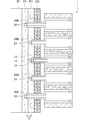
- the plant moisture dynamic sensor 1 includes one temperature probe with heater 10, a pair of temperature probes 20 ⁇ / b> A and 20 ⁇ / b> B, a pair of electric resistance probes 30 ⁇ / b> A and 30 ⁇ / b> B, and a support unit 80.
- Each probe 10, 20 ⁇ / b> A, 20 ⁇ / b> B, 30 ⁇ / b> A, 30 ⁇ / b> B is supported by the support portion 80 in a state where they are arranged in parallel in the same plane.
- the plant water dynamic sensor 1 is installed in the plant.
- the probes 10, 20A, 20B, 30A, and 30B and the support portion 80 are formed by processing an SOI substrate using MEMS technology using thin film formation such as photolithography, etching, sputtering, or vacuum evaporation. ing.
- the SOI substrate has a three-layer structure in which the oxide film layer BL is sandwiched between the support substrate SB and the active layer AL.
- the support substrate SB is made of silicon (Si) and has a thickness of 400 to 500 ⁇ m.
- the active layer AL is made of silicon (Si) and has a thickness of about 10 ⁇ m.
- the oxide film layer BL is made of silicon dioxide (SiO 2 ) and has a thickness of 0.1 to 1 ⁇ m.
- the active layer AL has thermal conductivity, and the oxide film layer BL is an insulator that hardly conducts heat and electricity.
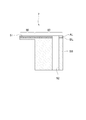
- the support unit 80 is a member that supports the probes 10, 20A, 20B, 30A, and 30B.
- the support part 80 is a plate member having a rectangular shape in plan view, and all the probes 10, 20A, 20B, 30A, 30B are supported on one long side part.
- the support portion 80 only needs to have such a length that the length in the longitudinal direction can arrange all the probes 10, 20 ⁇ / b> A, 20 ⁇ / b> B, 30 ⁇ / b> A, and 30 ⁇ / b> B with an inter-axis distance W described later. Is not particularly limited.
- the support unit 80 has a length in the longitudinal direction of about 12 mm and a length in the short direction in plan view. It can be formed to be about 8 mm.
- the thickness of the support part 80 is the same as the thickness of the SOI substrate. That is, the support part 80 is formed so that one side has a length of about several mm in plan view and a thickness of 1 mm or less.
- Each probe 10, 20 ⁇ / b> A, 20 ⁇ / b> B, 30 ⁇ / b> A, 30 ⁇ / b> B is a rod-like member formed of a thin plate, and is formed in a cantilever shape on the edge (long side portion) of the support portion 80.
- Each probe 10, 20A, 20B, 30A, 30B includes an active layer AL, an oxide film layer BL, and an upper portion of the support substrate SB. That is, the lower portion of the support substrate SB is removed, and the support substrate SB is formed thinner than the SOI substrate.
- the thickness of each probe 10, 20A, 20B, 30A, 30B is not particularly limited, but is 40 to 200 ⁇ m, for example.
- the thickness of the conduit XY and the phloem PH is about 100 to 200 ⁇ m. Therefore, if the thickness is 200 ⁇ m or less, the probes 10, 20A, 20B, 30A, and 30B are connected to the conduit XY and the phloem tube. Even if it is stabbed in PH, it can suppress blocking them.
- Each probe 10, 20A, 20B, 30A, 30B is dimensioned so that it can be stabbed into the details of a plant having a stem diameter or shaft diameter of about several millimeters, such as a shoot end or fruit handle of the plant. Is formed. Specifically, in a state where the length (length from the base end to the tip end in the axial direction) and the width are pierced and installed in the plant detail, the tip portion is the conduit XY and / or the mentor tube of the plant detail. It is formed to have a length (for example, 50 ⁇ m to 1 mm) and a width (for example, 50 to 300 ⁇ m) that can be arranged in the PH.
- each probe 10, 20A, 20B, 30A, 30B is preferably formed in a sharp shape such as a triangle. If the tips of the probes 10, 20A, 20B, 30A, and 30B are formed in a sharp shape, the insertion resistance when the probes 10, 20A, 20B, 30A, and 30B are inserted into plant details can be reduced. it can. That is, the probes 10, 20A, 20B, 30A, and 30B can be smoothly inserted into the plant details. For this reason, when the probe 10, 20A, 20B, 30A, 30B is pierced into the details of the plant, it is possible to prevent the tip of the probe 10, 20A, 20B, 30A, 30B from being damaged.
- the temperature probe with heater 10 is provided with a temperature sensor 11 and a heater 12.
- the dimensions of the temperature probe with heater 10 are, for example, a length of 300 ⁇ m and a width of 200 ⁇ m.
- the temperature sensor 11 has a function of sensing temperature, and is not particularly limited as long as it has a size that can be disposed at the tip of the temperature probe with heater 10 as described above.
- a temperature sensor 11 that is formed by a pn junction diode using an oxidation diffusion furnace can be used.
- the heater 12 has a function of supplying heat to the temperature probe 10 with heater, and is not particularly limited as long as it has a size that can be disposed on the temperature probe 10 with heater as described above. .
- a heater formed by a pn junction diode using an oxidation diffusion furnace can be used.
- the heater 12 should just be arrange
- a temperature sensor 21 is provided in each of the pair of temperature probes 20A and 20B.
- the dimensions of the temperature probes 20A and 20B may be the same as the dimensions of the temperature probe 10 with a heater.
- the length is 300 ⁇ m and the width is 200 ⁇ m.
- the temperature sensor 21 may be the same as the temperature sensor 11 of the heater-equipped temperature probe 10.
- the plant moisture dynamic sensor 1 is provided with two temperature probes 20A and 20B.
- the two temperature probes 20A and 20B are provided at positions where the temperature probe with heater 10 is sandwiched. That is, the temperature probe 20A, the heater-equipped temperature probe 10, and the temperature probe 20B are provided in this order.
- the pair of electrical resistance probes 30A and 30B are provided with a pair of electrical resistance measurement electrodes 33 and 33, respectively.
- the dimensions of the electric resistance probes 30A and 30B are longer than the lengths of the temperature probe with heater 10 and the temperature probes 20A and 20B. For example, the length is 400 ⁇ m and the width is 200 ⁇ m.
- the pair of electrical resistance measuring electrodes 33, 33 are electrodes for measuring the electrical resistance of substances existing between the electrical resistance measuring electrodes 33, 33, such as plant phloem fluid or conduit fluid.
- the electrical resistance measuring electrodes 33 and 33 are not particularly limited as long as they have a size that can be disposed at the tip portions of the electrical resistance probes 30A and 30B as described above.
- an aluminum (Al) thin plate can be employed as the electrical resistance measurement electrode 33.
- each electric resistance probe 30A, 30B is longer than the length of the temperature probe with heater 10 and the temperature probes 20A, 20B. Specifically, the length of each of the electric resistance probes 30A and 30B is greater than the length of the temperature probe with heater 10 and the temperature probes 20A and 20B, and the center of the phloem PH of the plant to be measured and the center of the conduit XY. It is formed longer by the distance of. The difference in length depends on the type of plant to be measured and the thickness of the stem, but is set to 50 to 300 ⁇ m, for example.
- the electrical resistance probes 30A, 30B are formed longer than the temperature probe 10 with heater and the temperature probes 20A, 20B, and an electrical resistance measurement electrode 33 is provided at the tip of the electrical resistance probes 30A, 30B.
- Temperature sensors 11 and 21 are disposed at the tip ends of the temperature probes 20A and 20B. Therefore, the electrical resistance measurement electrode 33 and the temperature sensors 11 and 21 are different from each other with a distance D in the direction of piercing the plant to be measured (the axial direction of each probe 10, 20A, 20B, 30A, and 30B). Placed in position.
- the electrical resistance measurement electrode 33 is arranged so that the distance from the proximal end of the probes 10, 20A, 20B, 30A, 30B is longer than the temperature sensors 11, 21, and reaches a deeper position of the plant. .
- the probe 10, 20A, 20B, 30A, 30B is stabbed into the plant, and the electrical resistance measurement electrode 33 is placed in the plant.
- the temperature sensors 11 and 21 are arranged at the position of the plant phloem PH.
- the distance D between the electrical resistance measurement electrode 33 and the temperature sensors 11 and 21 is such that the temperature sensors 11 and 21 are planted in a state where the electrical resistance measurement electrode 33 is disposed at the position of the plant conduit XY. It is set to be arranged at the position of the master pipe PH. This distance D depends on the type of plant to be measured and the thickness of the stem, but is set to 50 to 300 ⁇ m, for example.
- the plant moisture dynamic sensor 1 is provided with two electric resistance probes 30A and 30B.
- the two electric resistance probes 30A and 30B are provided at positions sandwiching the temperature probe with heater 10 and the temperature probes 20A and 20B. That is, the electrical resistance probe 30A, the temperature probe 20A, the temperature probe with heater 10, the temperature probe 20B, and the electrical resistance probe 30B are provided in this order.
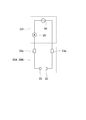
- the temperature sensors 11, 21, the heater 12, and the electrical resistance measurement electrode 33 provided in the plant moisture dynamic sensor 1 are connected to the data logger DR to supply power and collect various data.
- the active layer AL constituting each probe 10, 20A, 20B, 30A, 30B is connected to the active layer AL constituting the support portion 80, and is integrated.
- the active layer AL connected to each of the probes 10, 20A, 20B, 30A, and 30B has the active layer AL between them removed, and is thermally and electrically insulative.
- An oxide film layer BL is interposed. That is, the active layers AL of the probes 10, 20 ⁇ / b> A, 20 ⁇ / b> B, 30 ⁇ / b> A, 30 ⁇ / b> B are thermally and electrically independent by the oxide film layer B.
- Electrode pads 11e, 21e, 12e, and 33e are disposed on the active layer AL of the support portion 80, and are connected to the temperature sensors 11 and 21, the heater 12, and the electrical resistance measurement electrode 33, respectively.
- a pair of electrode pads 11e and 11e for the temperature sensor 11 and a heater 12 are formed on the active layer AL of the support 80 integrated with the active layer AL constituting the temperature probe 10 with heater.
- a pair of electrode pads 12e, 12e is provided.
- the temperature sensor 11 has an anode and a cathode (of a pn junction diode) connected to the electrode pad 11e via wiring.
- the heater 12 has its anode and cathode (of a pn junction diode) connected to the electrode pad 12e via wiring.
- a pair of electrode pads 21e and 21e for the temperature sensor 21 are disposed on the active layer AL of the support portion 80 integrated with the active layer AL constituting each temperature probe 20A and 20B.
- the temperature sensor 21 has an anode and a cathode (of a pn junction diode) connected to the electrode pad 21e via a wiring, respectively.
- a pair of electrode pads 33e and 33e for electric resistance measurement electrodes 33 and 33 are disposed on the active layer AL of the support portion 80 integrated with the active layer AL constituting each of the electric resistance probes 30A and 30B. Has been.
- the pair of electrical resistance measuring electrodes 33, 33 is connected to the electrode pad 33e via wiring.
- the electrode pads 11e, 12e, 21e, 33e and the wiring are formed together with the electrical resistance measuring electrode 33 by, for example, the following method.
- the data logger DR includes a constant current source 91 and a voltmeter 92.
- the constant current source 91 is connected between the electrode pads 11e and 11e (21e and 21e) and supplies a constant current in the forward direction to the temperature sensor 11 (21) which is a pn junction diode.
- the voltmeter 92 is connected between the electrode pads 11e and 11e (21e and 21e), and measures the voltage between the anode and the cathode of the temperature sensor 11 (21) which is a pn junction diode.
- the forward characteristics of a diode change with temperature, and that a voltage changes with temperature change when a constant current is passed through the diode.
- the voltage can be calculated by measuring the voltage of the temperature sensor 11 (21) with the voltmeter 92.
- the data logger DR includes a DC constant voltage source 93.
- the DC constant voltage source 93 is connected between the electrode pads 12e and 12e and supplies a constant voltage in the forward direction to the heater 12 which is a pn junction diode. Heat can be generated by passing a current through the heater 12.
- the data logger DR includes an AC power supply 94 and an ammeter 95.
- the AC power supply 94 and the ammeter 95 are connected in series between the electrode pads 33 e and 33 e, supply current between the pair of electrical resistance measuring electrodes 33 and 33 by the AC power supply 94, and a pair of ammeters 95.
- the current flowing between the electrical resistance measuring electrodes 33 and 33 is measured. Based on Ohm's law, the electrical resistance between the pair of electrical resistance measuring electrodes 33 and 33 can be calculated from the current measured by the ammeter 95.
- the plant moisture dynamic sensor 1 is formed by processing an SOI substrate using the MEMS technology.
- the method of forming each probe 10, 20A, 20B, 30A, 30B and the support part 80 using MEMS technology is demonstrated easily.
- pn junction diodes as the temperature sensors 11 and 21 and the heater 12 are formed on the active layer AL of the SOI substrate using an oxidation diffusion furnace. Specifically, after diffusion holes (p-type) are formed on the active layer AL, n diffusion (n-type) is formed. Next, contact formation of the pn junction diode and formation of the electrical resistance measurement electrode 33, electrode pads 11e, 12e, 21e, 33e, and wiring are performed. Specifically, an Al thin film is deposited on the active layer AL using a sputtering method or a vapor deposition method. A resist is applied on the Al thin film to form a contact and form an electrical resistance measurement electrode 33, electrode pads 11e, 12e, 21e, 33e and wiring.
- probe-shaped photolithography is performed on the surface of the SOI substrate, and the oxide film layer BL is etched using dry etching such as ICP-RIE to form a probe-shaped original. Thereafter, a part of the back surface of the SOI substrate is etched back so that the probes 10, 20A, 20B, 30A, and 30B are cantilevered.
- the plant moisture dynamic sensor 1 may be formed by a method other than the MEMS technique as long as it can be formed to have the above-described dimensions and functions, and the material is not limited to the SOI substrate.
- the plant water dynamic sensor 1 is attached to the end of a new treetop of a plant to be measured. Specifically, as shown in FIG. 6, all the probes 10, 20 ⁇ / b> A, 20 ⁇ / b> B, 30 ⁇ / b> A, 30 ⁇ / b> B of the plant water dynamic sensor 1 are attached to the plant by piercing it.
- the probes 10, 20A, 20B, 30A, and 30B are arranged along the flow direction of moisture (liquid) flowing in the details of the plant, that is, along the conduit XY and the phloem PH as in the above-described Granier method. To do. Note that it does not matter which of the temperature probes 20A and 20B is on the end side or the root side.
- the electrical resistance measurement electrodes 33 provided on the electrical resistance probes 30A, 30B Pass through the master pipe PH and reach the conduit XY. Furthermore, when pierced deeply, the electrical resistance measurement electrode 33 reaches the plant pith PI.
- the conduit fluid flowing in the conduit XY contains minerals, it has a property that its electrical resistance is lower than that of water contained in other portions (cortical layer CO, phloem PH, pith PI, etc.). Utilizing this, if the probe 10, 20A, 20B, 30A, 30B is pierced to a depth where the electrical resistance measured by the electrical resistance probe 30A, 30B is lowered, the electrical resistance measurement electrode 33 is brought to the position of the conduit XY. Can be arranged.
- the electrical resistance measurement electrode 33 and the temperature sensors 11 and 21 are arranged with a distance D in the piercing direction. Therefore, if the electrical resistance measurement electrode 33 is placed at the position of the conduit XY, the temperature sensors 11 and 21 are naturally placed at the position of the plant phloem PH.
- the plant water dynamic sensor 1 can be installed on a plant by simply piercing the plant with the probes 10, 20A, 20B, 30A, and 30B. Therefore, unlike conventional sensors for measuring the water dynamics of plants, operations such as drilling holes in stems or forming cuts in plants are unnecessary for installation in plants. The operation of attaching the moisture dynamic sensor 1 to a plant is easy.
- the electrical resistance probes 30A and 30B have a function of detecting the position of the conduit XY, and can detect the position of the conduit XY from the electrical resistance measured by the electrical resistance probes 30A and 30B.
- the probe 10, 20A, 20B, 30A, 30B is stabbed into the plant, if the electrical resistance probe 30A, 30B is stabbed to a depth at which the conduit XY is detected, the temperature sensors 11, 21 are accurately placed at the position of the phloem PH. can do.
- the two electric resistance probes 30A and 30B are provided at a position sandwiching the temperature probe with heater 10 and the temperature probes 20A and 20B, that is, an outer position as in the present embodiment, the two electric resistance probes 30A are provided. , 30B, and the temperature sensors 11, 21 can be more accurately arranged along the phloem PH.
- the water movement of the plant is measured using the plant water movement sensor 1 attached to the plant.
- the heater 12 provided in the temperature probe with heater 10 is operated. If the heater 12 is operated, the thermal energy supplied from the heater 12 is supplied to the temperature probe 10 with heater. The thermal energy supplied to the temperature probe with heater 10 is released from the surface of the temperature probe with heater 10 into the phloem liquid flowing in the phloem PH.
- the temperature of the temperature probe with heater 10 and the temperature probes 20A and 20B can be measured by the temperature sensors 11 and 21. Then, by comparing the temperatures measured by the two temperature probes 20A and 20B, the direction of the phloem flow can be specified.
- the two temperature probes 20A and 20B are provided at a position sandwiching the temperature probe with heater 10, the phloem fluid flows from the end of the plant toward the root (in the direction of the white arrow in FIG. 7). This is because the temperature probe 20A located on the root side is warmed by the phloem solution heated by the temperature probe with heater 10 and the temperature becomes higher than the temperature probe 20B on the end side.
- the temperature probe 20B located on the end side is warmed by the phloem sap heated by the temperature probe 10 with heater, The temperature is detected higher than that of the temperature probe 20A.
- the direction of the phloem flow can be specified as the direction from the low temperature probe 20B (20A) to the high temperature probe 20A (20B).
- the conduit flow flows from the root of the plant toward the end, but the direction of the phloem flow cannot be grasped from the outline of the plant.
- the direction of the phloem flow can be specified.
- the flow rate (flow velocity) of the phloem flow flowing in the shoot end is measured based on the above-mentioned Granier method.
- it calculates based on the temperature difference of the temperature probe 20B (20A) with a low temperature and the temperature probe 10 with a heater among the two temperature probes 20A and 20B. This is because the temperature probe 20 ⁇ / b> B (20 ⁇ / b> A) having a low temperature is arranged on the upstream side of the phloem flow with respect to the temperature probe with heater 10.
- the phloem solution near the temperature probe with heater 10 is always replaced with a new phloem solution. For this reason, if the thermal energy supplied to the temperature probe with heater 10 is constant, the temperature of the temperature probe with heater 10 is carried away by the phloem liquid in the vicinity of the temperature probe with heater 10. On the other hand, when the flow rate of the phloem flow is small (the flow rate is slow), the phloem solution near the temperature probe 10 with heater is in a staying state, so that the heat energy supplied to the temperature probe 10 with heater is supplied. Is constant, the temperature of the heater-equipped temperature probe 10 is in an accumulated state.
- the flow velocity and flow rate of the phloem flow can be calculated by measuring the temperature difference ⁇ T between the temperature probe with heater 10 and the temperature probe 20B (20A).
- the thermal energy supplied from the heater 12 to the temperature probe 10 with heater is not supplied to the temperature probes 20A and 20B. This is because the thermal energy supplied from the heater 12 is blocked by the oxide film layer BL from being supplied to the adjacent temperature probes 20A and 20B.
- the plant moisture dynamic sensor 1 By forming the plant moisture dynamic sensor 1 with an SOI substrate, the plant moisture dynamic sensor 1 can be miniaturized and the probes 10, 20A, 20B, 30A, and 30B can be miniaturized. For this reason, even if the plant water dynamic sensor 1 is installed in a plant, damage (damage) to the plant can be reduced, so that it can be installed for a long period of time. As a result, the water dynamics of the plant can be monitored over a long period of time, so that appropriate water supply and nutrient replenishment (fertilization) can be performed according to the growth state of the plant.
- the probes 10, 20A, 20B, 30A, and 30B are miniaturized, even if the probes 10, 20A, 20B, 30A, and 30B are pierced and installed in the plant, the stress applied to the plant can be reduced. . In other words, the fluctuation of the water dynamics in the plant installation site before and after the installation of the probes 10, 20A, 20B, 30A, 30B can be reduced. For this reason, after installing the probe 10, 20A, 20B, 30A, 30B in the plant, it is possible to measure the moisture dynamics of the water (liquid) flowing in the installation site immediately. Moreover, it can be easily attached to details such as the shoot end and fruit handle of a plant, which was difficult to install with conventional sensors.
- the temperature probe 10 with a heater and the temperature probes 20A and 20B have a flow rate (flow velocity) of moisture (liquid) flowing in the details when the inter-axis distance W is in the state where the probes 10, 20A and 20B are attached to the details of the plant. It forms so that it may become a distance which can be measured.
- the inter-axis distance W of each probe 10, 20A, 20B may be 1 to 20 mm.
- the thermal energy supplied from the heater 12 may be supplied to the temperature probes 20A and 20B via the plant tissue or the like.
- the inter-axis distance W is longer than 20 mm, there is a possibility that the flow of moisture (liquid) flowing in the details of the plant cannot be accurately detected. If the inter-axis distance W is in the above-described range, the moisture dynamics can be accurately measured in a state where the probes 10, 20A, and 20B are installed in details such as the shoot end of the plant.
- the inter-axis distances W of the probes 10, 20A, 20B, 30A, 30B may all be the same or different.
- the plant moisture dynamic sensor 2 according to the second embodiment of the present invention is a sensor particularly suitable for measuring the direction and flow rate (flow velocity) of the conduit flow.
- the plant water dynamic sensor 2 is a form in which all the probes 10, 20A, 20B, 30A, and 30B have the same length in the plant water dynamic sensor 1 according to the first embodiment.
- the dimensions of the probes 10, 20A, 20B, 30A, and 30B are, for example, 400 ⁇ m in length and 200 ⁇ m in width.
- the lengths of all the probes 10, 20A, 20B, 30A and 30B are the same, and the temperature sensors 11 and 21 are connected to the tips of the temperature probe 10 with heater and the temperature probes 20A and 20B, and the electric resistance probes 30A and 30B.
- An electrode 33 for measuring electrical resistance is disposed at the tip. Therefore, the temperature sensors 11 and 21 and the electrical resistance measurement electrode 33 are arranged at the same position in the piercing direction to the plant to be measured.
- the temperature sensors 11 and 21 and the electric resistance measurement electrode 33 are arranged at the same position, so that the probe 10, 20A, 20B, 30A, and 30B are pierced into the plant, and the electric resistance measurement electrode 33 is inserted. If it is set as the state arrange
- all the probes 10, 20A, 20B, 30A, and 30B may be inserted into the plant details.
- the electrical resistance probes 30A and 30B are pierced to a depth at which the conduit XY is detected, the temperature sensors 11 and 21 can be accurately arranged at the position of the conduit XY. Therefore, the attachment work of the plant moisture dynamic sensor 2 is easy, and the flow rate of the conduit flow can be accurately measured.
- the temperature sensors 11 and 21 are moved along the conduit XY. Can be arranged.
- the direction of the conduit flow can be specified by operating the heater 12 provided in the temperature probe with heater 10 and comparing the temperatures measured by the two temperature probes 20A and 20B. Further, the flow rate (flow velocity) of the conduit flow can be measured based on the temperature difference between the low temperature probe 20A (20B) and the heater-equipped temperature probe 10 out of the two temperature probes 20A and 20B.
- the plant water movement sensor 3 according to the present embodiment is a sensor particularly suitable for measuring the flow rate (flow velocity) of the conduit flow.
- the plant water dynamic sensor 3 is a form in which the temperature probe 20 is one in the plant water dynamic sensor 2 according to the second embodiment. That is, the plant moisture dynamic sensor 3 includes one temperature probe 10 with a heater, one temperature probe 20, and a pair of electrical resistance probes 30A and 30B.
- Temperature sensors 11 and 21 are provided at the distal ends of the temperature probe 10 with heater and the temperature probe 20, and the distal ends of the electrical resistance probes 30A and 30B.
- An electrode 33 for measuring electrical resistance is provided. Therefore, the temperature sensors 11 and 21 and the electrical resistance measurement electrode 33 are arranged at the same position in the piercing direction to the plant to be measured.
- the temperature probe 20 is disposed on the upstream side of the conduit flow, and the temperature probe with heater 10 is disposed on the downstream side. It is generally known that the conduit flow flows from the root of the plant toward the end. Therefore, the temperature probe 20 may be disposed on the root side of the plant, and the temperature probe with heater 10 may be disposed on the end side.
- the temperature sensor 11, 21 can be accurately placed at the position of the conduit XY if the electrical resistance probes 30A, 30B are inserted to a depth at which the conduit XY is detected. it can. Therefore, the attachment work of the plant moisture dynamic sensor 3 is easy, and the flow rate of the conduit flow can be accurately measured.
- the temperature sensors 11, 21 are arranged along the conduit XY. be able to.
- the flow rate (flow velocity) of the conduit flow can be measured from the temperature difference between the temperature probe with heater 10 and the temperature probe 20.
- the plant water dynamic sensor 4 according to the present embodiment is a sensor particularly suitable for measuring the direction of the phloem flow and the flow rate (flow velocity).
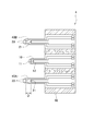
- the plant moisture dynamic sensor 4 is an electrical probe in which the electrical resistance probes 30A and 30B and the temperature probes 20A and 20B are formed as an integral probe in the plant moisture dynamic sensor 1 according to the first embodiment. It is a form provided with resistance and temperature probes 40A and 40B. That is, the plant moisture dynamic sensor 4 includes one temperature probe 10 with a heater and a pair of electric resistance / temperature probes 40A and 40B.
- the dimensions of the temperature probe with heater 10 are, for example, a length of 300 ⁇ m and a width of 200 ⁇ m.
- the electrical resistance / temperature probes 40A and 40B are formed so that the length is longer than the length of the temperature probe 10 with a heater, for example, the length is 400 ⁇ m and the width is 200 ⁇ m.
- a temperature sensor 11 is disposed at the tip of the temperature probe with heater 10.
- a pair of electrical resistance measuring electrodes 33, 33 is disposed at the tip of each electrical resistance / temperature probe 40A, 40B, and is the same as the temperature sensor 11 of the temperature probe with heater 10 in the piercing direction to the plant.
- a temperature sensor 21 is disposed at the position. That is, the electrical resistance measuring electrode 33 and the temperature sensors 11 and 21 are arranged at different positions with a distance D in the piercing direction to the plant to be measured.
- all the probes 10, 40A and 40B may be pierced into the plant details. At that time, if the electric resistance / temperature probes 40A, 40B are pierced to a depth at which the conduit XY is detected, the temperature sensors 11, 21 can be accurately arranged at the position of the phloem PH. Therefore, the attachment work of the plant moisture dynamic sensor 5 is easy, and the flow rate of the phloem flow can be accurately measured.
- the direction of the phloem flow can be specified.
- the flow rate (flow velocity) of the phloem flow can be measured.
- the plant moisture dynamic sensor 4 can be reduced in size. Further, since the number of the probes 10, 40A, 40B is small, damage (damage) to the plant can be further reduced.
- the plant water dynamic sensor 4 according to the present embodiment is a sensor particularly suitable for measuring the direction and flow rate (flow velocity) of the conduit flow.
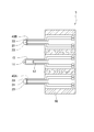
- the plant water dynamic sensor 5 is an electric water probe in which the electrical resistance probes 30A and 30B and the temperature probes 20A and 20B are formed as an integral probe in the plant water dynamic sensor 2 according to the second embodiment. It is a form provided with resistance and temperature probes 40A and 40B. That is, the plant moisture dynamic sensor 5 includes one temperature probe 10 with a heater and a pair of electric resistance / temperature probes 40A and 40B.
- the dimensions of the temperature probe with heater 10 and the electrical resistance / temperature probes 40A, 40B are the same, for example, 400 ⁇ m in length and 200 ⁇ m in width.
- a temperature sensor 11 is disposed at the tip of the temperature probe with heater 10.
- a pair of electrical resistance measuring electrodes 33 and 33 and a temperature sensor 21 are disposed at the distal ends of the electrical resistance / temperature probes 40A and 40B. That is, the electrical resistance measurement electrode 33 and the temperature sensors 11 and 21 are disposed at the same position in the direction of piercing the plant to be measured.
- all the probes 10, 40A, and 40B may be inserted into the plant details. At this time, if the electric resistance / temperature probes 40A and 40B are pierced to a depth at which the conduit XY is detected, the temperature sensors 11 and 21 can be accurately arranged at the position of the conduit XY. Therefore, the attachment work of the plant moisture dynamic sensor 5 is easy, and the flow rate of the phloem flow can be accurately measured.
- the direction of the conduit flow can be specified by operating the heater 12 provided in the temperature probe with heater 10 and comparing the temperatures measured by the two electric resistance / temperature probes 40A and 40B. Also, the flow rate (flow velocity) of the conduit flow is determined based on the temperature difference between the electric resistance / temperature probe 40A (40B) having a low temperature and the temperature probe 10 with heater, out of the two electric resistance / temperature probes 40A, 40B. It can be measured.
- the plant moisture dynamic sensor 5 can be reduced in size. Further, since the number of the probes 10, 40A, 40B is small, damage (damage) to the plant can be further reduced.
- the electrical resistance probe 30 and the temperature probe 20 are formed as an integral probe, but the electrical resistance probe 30 and the temperature probe with heater 10 may be formed as an integral probe.
- the plant moisture dynamic sensor can be miniaturized.
- damage (damage) to plants can be further reduced.
- the plant moisture dynamic sensor 7 according to a seventh embodiment of the present invention is a sensor suitable for analyzing nutrient substances in sap.
- the plant moisture dynamic sensor 7 includes a collection probe 50.
- the plant moisture dynamic sensor 7 includes a temperature probe 10 with a heater, a temperature probe 20, and an electrical resistance probe 30 as in the first to sixth embodiments.
- the collecting probe 50 is supported by the support portion 80 in a state where the collecting probe 50 is arranged in parallel in the same plane together with the other probes 10, 20, and 30. By planting these probes 10, 20, 30, and 50 into the plant, the plant moisture dynamic sensor 7 is installed in the plant.
- the collection probe 50 is a probe having substantially the same dimensions as the other probes 10, 20, and 30.
- a groove-shaped flow path 51 is formed along the axis.
- the support portion 80 is formed with a through hole 52 penetrating the front and back.
- the flow path 51 is formed from the front end to the end of the collection probe 50 and further reaches the through hole 52 of the support portion 80.
- the formation of the flow path 51 and the through hole 52 is performed by the following method, for example. First, a resist pattern for the flow path 51 and the through hole 52 is formed on the surfaces of the collection probe 50 and the support portion 80. Next, the channel 51 and the through hole 52 are formed by wet etching or dry etching. Thereafter, the resist pattern that has become unnecessary is removed.
- the conduit fluid flows into the flow channel 51 and is guided to the through hole 52.
- the tip of the collection probe 50 is arranged in the phloem PH of the plant, the phloem liquid flows into the channel 51 and is guided to the through hole 52.
- the sap (conduit fluid or phloem fluid) guided to the through hole 52 can be collected by a pump or the like connected to the back surface of the support portion 80. In this way, plant sap can be collected via the flow path 51.
- the collected sap can be brought back to the laboratory and analyzed with a device such as liquid chromatography to analyze nutrients and the like.
- a device such as liquid chromatography to analyze nutrients and the like.
- the sap can be collected by the collection probe 50, it can be used for analysis of the nutrient substance contained in the sap.
- the collection probe 50 is a probe independent of the other probes 10, 20, 30.
- the collection probe 50 is integrated with the temperature probe 10 with heater, the temperature probe 20, or the electrical resistance probe 30. It may be formed as a probe.
- FIGS. 14 and 15 is a form including a collection and temperature probe 60 in which the collection probe 50 and the temperature probe 20 are integrated.
- a flow path 51 is formed in the collection / temperature probe 60 along the axis. That is, the collection and temperature probe 60 is formed in a hollow needle shape.
- wiring connected to the temperature sensor 21 and the electrode pad 21e is disposed on the surface of the collection and temperature probe 60.
- the plant moisture dynamic sensor 8 of this embodiment has a structure in which a borosilicate glass substrate GB and a silicon substrate SL are bonded together. By forming a groove for the flow path 51 on the surface of the borosilicate glass substrate GB and pasting the silicon substrate SL thereon, the flow path 51 enclosed in the collection and temperature probe 60 is formed. Further, a through hole 52 communicating with the flow path 51 is also formed in the borosilicate glass substrate GB.
- the collection and temperature probe 60 is formed by disposing the temperature sensor 21 and wiring on the surface of the silicon substrate SL. By changing the member disposed on the surface of the silicon substrate SL, the collecting probe 50 and the temperature probe with heater 10 can be integrated, or the collecting probe 50 and the electric resistance probe 30 can be combined. An integrated probe can also be used.
- the plant moisture dynamic sensor 8 can be miniaturized.
- damage (damage) to plants can be further reduced.
- the probe is formed in a cantilever shape parallel to the surface of the flat plate-like support portion 80. Instead, the probe is erected vertically on the surface of the flat plate-like support portion 80. You may form so.
- a probe can be formed by the following method, for example. First, after forming a resist mask to be a probe-shaped mold on a Si substrate, conical processing is performed by crystal anisotropic etching. Thereafter, a cylindrical shape is formed by vertical etching. Finally, a mask is formed by removing unnecessary mask material.
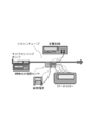
- Plant moisture dynamics information collection system The above-mentioned plant moisture dynamic sensors 1 to 8 (hereinafter simply referred to as plant moisture dynamic sensor 1) wire measurement data such as the flow rate (flow velocity) of moisture (liquid) flowing in details such as the shoot end of a plant.
- plant moisture dynamic sensor 1 wire measurement data such as the flow rate (flow velocity) of moisture (liquid) flowing in details such as the shoot end of a plant.
- a plurality of plant moisture dynamic sensors 1 are attached to a plurality of plants on an agricultural site.
- the plant moisture dynamic sensor 1 may be attached to a plurality of locations of one plant, or may be attached to all of a plurality of plants or a part of a specimen.
- the data logger DR is connected to each plant water movement sensor 1 to supply power and collect various data.
- This data logger DR includes a wireless communication device in addition to the constant current source 91, the voltmeter 92, the DC constant voltage source 93, the AC power supply 94, and the ammeter 95 described above.
- a server device SV for centrally managing plant water dynamics information is provided in a building adjacent to an agricultural site.
- a wireless communication device is also connected to the server device SV, and is configured to be able to wirelessly communicate with the data logger DR.
- Each data logger DR transmits the measurement data of the plant moisture dynamic sensor 1 to the server device SV via the wireless communication device.
- the server device SV centrally manages the received measurement data. By analyzing the measurement data with the server device SV, the plant can be used for water supply, nutrient supply (fertilization), and the like.
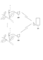
- the experimental apparatus shown in FIG. 17 was created.
- the experimental apparatus includes a pair of needle electrodes, a micrometer, and a multimeter.
- the diameter of the needle electrode is 0.55 mm.
- a pair of needle electrodes was pierced into the plant with a multimeter, and the electrical resistance between the needle electrodes was measured with a multimeter.
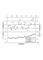
- FIG. 18 is a graph showing the relationship between the penetration depth of the needle electrode and the electrical resistance.
- the electric resistance in the depth range of about 150 to 300 ⁇ m is lower than the electric resistance in the other ranges. Since the conduit fluid flowing in the conduit contains minerals, it has a property that its electrical resistance is lower than the moisture contained in other portions. Therefore, it is considered that the range where the electric resistance is low is the range of the conduit. From the above, it was confirmed that the position of the conduit can be detected from the electrical resistance measured by the electrical resistance probe.
- FIG. 20 is a graph showing the time change from the temperature at the start of temperature measurement of the temperature probe with heater 10 and the temperature probes 20A and 20B when the flow rate (average sap flow rate) of the syringe pump is 100 ⁇ m / s. is there.
- the temperature probe 20A on the upstream side is lower in temperature than the temperature probe 20B on the downstream side. From this, it was confirmed that the direction of the sap flow can be specified by comparing the temperatures measured by the two temperature probes 20A and 20B.
- FIG. 21 is a graph showing the relationship between the flow rate (average sap flow velocity u) of the micro syringe pump and the K value.
- the K value is obtained from the temperature difference between the temperature probe with heater 10 and the upstream temperature probe 20A (see Equation 1).
- the coefficients 1 / ⁇ and 1 / ⁇ in Equation 1 were determined to be 0.095 and 0.828, respectively. From this, it was confirmed that the flow rate of the sap flow can be measured.
- the plant water movement sensor of the present invention is suitable for measuring the water movement of plants.
Landscapes
- Life Sciences & Earth Sciences (AREA)
- Engineering & Computer Science (AREA)
- Chemical & Material Sciences (AREA)
- General Physics & Mathematics (AREA)
- Physics & Mathematics (AREA)
- Environmental Sciences (AREA)
- Health & Medical Sciences (AREA)
- Botany (AREA)
- Biodiversity & Conservation Biology (AREA)
- Forests & Forestry (AREA)
- Ecology (AREA)
- Biochemistry (AREA)
- Pathology (AREA)
- Immunology (AREA)
- General Health & Medical Sciences (AREA)
- Analytical Chemistry (AREA)
- Aviation & Aerospace Engineering (AREA)
- Wood Science & Technology (AREA)
- Water Supply & Treatment (AREA)
- Medicinal Chemistry (AREA)
- Food Science & Technology (AREA)
- Chemical Kinetics & Catalysis (AREA)
- Electrochemistry (AREA)
- Soil Sciences (AREA)
- Investigating Or Analyzing Materials By The Use Of Electric Means (AREA)
- Measuring Volume Flow (AREA)
Abstract
Description
第2発明の植物水分動態センサは、第1発明において、前記電気抵抗測定用電極および前記温度センサは、前記植物への突き刺し方向に異なる位置に配置されており、前記電気抵抗測定用電極を前記植物の導管の位置に配置した状態において、前記温度センサが該植物の師管の位置に配置されることを特徴とする。
第3発明の植物水分動態センサは、第1発明において、前記温度センサおよび前記電気抵抗測定用電極は、前記植物への突き刺し方向に同位置に配置されていることを特徴とする。
第4発明の植物水分動態センサは、第1、第2または第3発明において、前記電気抵抗プローブが2つ備えられていることを特徴とする。
第5発明の植物水分動態センサは、第1、第2、第3または第4発明において、前記温度プローブが2つ備えられており、2つの前記温度プローブは、前記ヒータ付温度プローブを挟む位置に設けられていることを特徴とする。
第6発明の植物水分動態センサは、第1、第2、第3、第4または第5発明において、前記電気抵抗プローブは、前記ヒータ付温度プローブまたは前記温度プローブと一体のプローブとして形成されていることを特徴とする。
第7発明の植物水分動態センサは、第1、第2、第3、第4、第5または第6発明において、前記植物の樹液が流入する流路が形成された捕集プローブを備えることを特徴とする。
第8発明の植物水分動態センサは、第7発明において、前記捕集プローブは、前記ヒータ付温度プローブ、前記温度プローブ、または前記電気抵抗プローブと一体のプローブとして形成されていることを特徴とする。
第9発明の植物水分動態センサは、第1、第2、第3、第4、第5、第6、第7または第8発明において、前記ヒータ付温度プローブ、前記温度プローブ、前記電気抵抗プローブおよび前記支持部は、SOI基板で形成されており、前記ヒータ付温度プローブ、前記温度プローブおよび前記電気抵抗プローブは、前記支持部の縁に片持ち梁状に形成されていることを特徴とする。
第2発明によれば、プローブを植物に突き刺す際に、電気抵抗プローブが導管を検出する深さまで突き刺せば、温度センサを師管の位置に正確に配置することができる。そのため、植物水分動態センサの取り付け作業が容易であり、師管流の流量等を精度よく測定することができる。
第3発明によれば、プローブを植物に突き刺す際に、電気抵抗プローブが導管を検出する深さまで突き刺せば、温度センサを導管の位置に正確に配置することができる。そのため、植物水分動態センサの取り付け作業が容易であり、導管流の流量等を精度よく測定することができる。
第4発明によれば、プローブを植物に突き刺す際に、2つの電気抵抗プローブが導管を検出する深さまで突き刺せば、温度センサを師管または導管に沿って配置することができる。
第5発明によれば、2つの温度プローブで測定された温度を比較することで、樹液流の方向を特定できる。
第6発明によれば、プローブの本数を少なくできるので、植物水分動態センサを小型化することができる。また、プローブの本数を少なくできるので、植物に対するダメ-ジをより小さくできる。
第7発明によれば、捕集プローブにより樹液を捕集できるので、樹液に含まれる栄養物質の分析に用いることができる。
第8発明によれば、プローブの本数を少なくできるので、植物水分動態センサを小型化することができる。また、プローブの本数を少なくできるので、植物に対するダメ-ジをより小さくできる。
第9発明によれば、植物水分動態センサを小型化することができ、プローブを微細化できる。そのため、かかる植物水分動態センサを植物に設置しても植物に対するダメ-ジ(損傷)を小さくできるので、長期間設置させておくことができる。その結果、植物の水分動態を長期間に渡ってモニタリングすることができるので、植物の生育状態に合わせて適切な水分供給や養分補給(施肥)を行うことができる。
本発明に係る植物水分動態センサは、植物中の水分動態を測定するためのセンサであって、植物の新梢の末端(以下、単に新梢末端という)や果柄等の植物の細部にも容易に取り付けることができ、かかる細部における水分動態測定を行うことができるセンサである。

つぎに、本発明の第1実施形態に係る植物水分動態センサ1について説明する。
本実施形態に係る植物水分動態センサ1は、特に師管流の方向および流量(流速)を測定するのに適したセンサである。
支持部80は、プローブ10、20A、20B、30A、30Bを支持する部材である。支持部80は、平面視長方形の板材であり、片方の長辺部に全てのプローブ10、20A、20B、30A、30Bが支持されている。支持部80は、その長手方向の長さが全てのプローブ10、20A、20B、30A、30Bを後述の軸間距離Wで配置できる長さを有していればよく、短手方向の長さは特に限定されない。
各プローブ10、20A、20B、30A、30Bは、薄板で形成された棒状の部材であり、支持部80の縁(長辺部)に片持ち梁状に形成されている。各プローブ10、20A、20B、30A、30Bは、活性層ALと、酸化膜層BLと、支持基板SBの上部とから構成されている。すなわち、支持基板SBの下部が除去されており、SOI基板の厚みより薄く形成されている。各プローブ10、20A、20B、30A、30Bの厚みは特に限定されないが、例えば、40~200μmである。厚みが40μm以上であれば強度が十分であり、プローブ10、20A、20B、30A、30Bを植物に挿抜する際に折れる恐れがない。また、植物の種類にもよるが導管XYや師管PHの太さは100~200μm程度であるため、厚みが200μm以下であればプローブ10、20A、20B、30A、30Bを導管XYや師管PHに刺してもそれらを塞ぐことを抑制できる。
ヒータ付温度プローブ10には、温度センサ11とヒータ12とが設けられている。ヒータ付温度プローブ10の寸法は、例えば、長さが300μm、幅が200μmである。
一対の温度プローブ20A、20Bには、それぞれ温度センサ21が設けられている。各温度プローブ20A、20Bの寸法は、ヒータ付温度プローブ10の寸法と同じとすればよく、例えば、長さが300μm、幅が200μmである。温度センサ21は、ヒータ付温度プローブ10の温度センサ11と同様のものを採用することができる。
一対の電気抵抗プローブ30A、30Bには、それぞれ一対の電気抵抗測定用電極33、33が設けられている。各電気抵抗プローブ30A、30Bの寸法は、長さが、ヒータ付温度プローブ10および温度プローブ20A、20Bの長さよりも長く形成されており、例えば、長さが400μm、幅が200μmである。
植物水分動態センサ1に設けられた温度センサ11、21、ヒータ12、および電気抵抗測定用電極33は、データロガーDRに接続され、電力の供給および各種データの収集が行われる。
前述のごとく、植物水分動態センサ1はMEMS技術を用いて、SOI基板を加工することで形成されている。以下では、各プローブ10、20A、20B、30A、30Bおよび支持部80をMEMS技術に用いて形成する方法について簡単に説明する。
(取り付け方法)
まず、測定対象となる植物の新梢末端に、植物水分動態センサ1を取り付ける。
具体的には、図6に示すように、植物水分動態センサ1の全てのプローブ10、20A、20B、30A、30Bを植物の細部に突き刺して取り付ける。このとき、上述したグラニエ法と同様に植物の細部中に流れる水分(液体)の流れ方向に沿って、すなわち導管XYおよび師管PHに沿って、プローブ10、20A、20B、30A、30Bを配置する。なお、温度プローブ20A、20Bのどちらを末端側または根本側にするかは問わない。
つぎに、植物に取り付けた植物水分動態センサ1を用いて植物の水分動態を測定する。
まず、ヒータ付温度プローブ10に設けられたヒータ12を作動させる。ヒータ12を作動すれば、ヒータ12から供給された熱エネルギは、ヒータ付温度プローブ10に供給される。ヒータ付温度プローブ10に供給された熱エネルギは、ヒータ付温度プローブ10の表面から師管PH内を流れる師管液に放出される。
つぎに、本発明の第2実施形態に係る植物水分動態センサ2について説明する。
本実施形態に係る植物水分動態センサ2は、特に導管流の方向および流量(流速)を測定するのに適したセンサである。
つぎに、本発明の第3実施形態に係る植物水分動態センサ3について説明する。
本実施形態に係る植物水分動態センサ3は、特に導管流の流量(流速)を測定するのに適したセンサである。
つぎに、本発明の第4実施形態に係る植物水分動態センサ4について説明する。
本実施形態に係る植物水分動態センサ4は、特に師管流の方向および流量(流速)を測定するのに適したセンサである。
つぎに、本発明の第5実施形態に係る植物水分動態センサ5について説明する。
本実施形態に係る植物水分動態センサ4は、特に導管流の方向および流量(流速)を測定するのに適したセンサである。
上記第4、第5実施形態では、電気抵抗プローブ30と温度プローブ20を一体のプローブとして形成したが、電気抵抗プローブ30とヒータ付温度プローブ10とを一体のプローブとして形成してもよい。
つぎに、本発明の第7実施形態に係る植物水分動態センサ7について説明する。
本実施形態に係る植物水分動態センサ7は、樹液の栄養物質を分析するのに適したセンサである。
第7実施形態では、捕集プローブ50を他のプローブ10、20、30とは独立のプローブとしたが、捕集プローブ50をヒータ付温度プローブ10、温度プローブ20、または電気抵抗プローブ30と一体のプローブとして形成してもよい。
上記実施形態では、プローブを平板状の支持部80の表面に平行な片持ち梁状に形成しているが、これに代えて、プローブを平板状の支持部80の表面に垂直に立設するよう形成してもよい。このようなプローブは、例えば以下の方法で形成できる。まず、Si基板上にプローブの形状の型となるレジストマスクを形成した後、結晶異方性エッチングにより円錐形状加工を行う。その後、垂直方向性エッチングにより円筒形状を形成する。最後に、不要となるマスク材料を除去することによって、プローブを形成する。
上述の植物水分動態センサ1~8(以下、単に植物水分動態センサ1とする。)は、植物の新梢末端等の細部内を流れる水分(液体)の流量(流速)等の測定データを配線や無線通信機等を介してサーバ装置等に送信し、集中管理することで、植物に水分供給や養分補給(施肥)等を行うのに役立てることができる。
まず、温度センサの温度特性実験を行った。
その結果、温度センサは、16.6~75.7℃の範囲において、感度-5.6mv/℃で測定可能であることが確認できた。
つぎに、ヒータの温度上昇実験を行った。
その結果、ヒータは、310mWの直流電圧を印加することで、常温~67℃まで昇温できることが確認できた。
つぎに、電気抵抗による位置検出の実験を行った。
図17に示す実験装置を作成した。実験装置は、一対の針状電極と、マイクロメータと、マルチメータとを備えている。針状電極の直径は0.55mmである。一対の針状電極をマルチメータで植物に突き刺し、針状電極間の電気抵抗をマルチメータで測定した。
つぎに、樹液流の方向、流量測定実験を行った。
図19に示す疑似植物実験系を用いて実験を行った。この疑似植物実験系では、シリコンチューブ(直径1mm、厚さ0.2mm)の中に、マイクロシリンジポンプで水を流し込むことで疑似的な維管束を形成した。この疑似的な維管束に、上記第1実施形態に係る植物水分動態センサ1のプローブを突き刺した。シリコンチューブ内の流量はマイクロシリンジポンプにより精密に制御することができる。植物水分動態センサには、温度センサのための定電流源、ヒータのための直流電源、およびデータ取得のためのデータロガーを接続した。
10 ヒータ付温度プローブ
11 温度センサ
12 ヒータ
20 温度プローブ
21 温度センサ
30 電気抵抗プローブ
33 電気抵抗測定用電極
40 電気抵抗兼温度プローブ
50 捕集プローブ
51 流路
52 貫通孔
60 捕集兼温度プローブ
80 支持部
Claims (9)
- 植物中の水分動態を測定するためのセンサであって、
温度センサとヒータとが設けられたヒータ付温度プローブと、
温度センサが設けられた温度プローブと、
電気抵抗測定用電極が設けられた電気抵抗プローブと、
前記ヒータ付温度プローブ、前記温度プローブおよび前記電気抵抗プローブを平行に並べた状態で支持する支持部と、を備える
ことを特徴とする植物水分動態センサ。 - 前記電気抵抗測定用電極および前記温度センサは、前記植物への突き刺し方向に異なる位置に配置されており、
前記電気抵抗測定用電極を前記植物の導管の位置に配置した状態において、前記温度センサが該植物の師管の位置に配置される
ことを特徴とする請求項1記載の植物水分動態センサ。 - 前記温度センサおよび前記電気抵抗測定用電極は、前記植物への突き刺し方向に同位置に配置されている
ことを特徴とする請求項1記載の植物水分動態センサ - 前記電気抵抗プローブが2つ備えられている
ことを特徴とする請求項1、2または3記載の植物水分動態センサ。 - 前記温度プローブが2つ備えられており、
2つの前記温度プローブは、前記ヒータ付温度プローブを挟む位置に設けられている
ことを特徴とする請求項1、2、3または4記載の植物水分動態センサ。 - 前記電気抵抗プローブは、前記ヒータ付温度プローブまたは前記温度プローブと一体のプローブとして形成されている
ことを特徴とする請求項1、2、3、4または5記載の植物水分動態センサ。 - 前記植物の樹液が流入する流路が形成された捕集プローブを備える
ことを特徴とする請求項1、2、3、4、5または6記載の植物水分動態センサ。 - 前記捕集プローブは、前記ヒータ付温度プローブ、前記温度プローブ、または前記電気抵抗プローブと一体のプローブとして形成されている
ことを特徴とする請求項7記載の植物水分動態センサ。 - 前記ヒータ付温度プローブ、前記温度プローブ、前記電気抵抗プローブおよび前記支持部は、SOI基板で形成されており、
前記ヒータ付温度プローブ、前記温度プローブおよび前記電気抵抗プローブは、前記支持部の縁に片持ち梁状に形成されている
ことを特徴とする請求項1、2、3、4、5、6、7または8記載の植物水分動態センサ。
Priority Applications (3)
| Application Number | Priority Date | Filing Date | Title |
|---|---|---|---|
| US15/115,866 US9857391B2 (en) | 2014-02-03 | 2015-01-26 | Plant water dynamics sensor |
| EP15743603.1A EP3104135B1 (en) | 2014-02-03 | 2015-01-26 | Plant moisture movement state sensor |
| AU2015212258A AU2015212258B2 (en) | 2014-02-03 | 2015-01-26 | Plant water dynamics sensor |
Applications Claiming Priority (2)
| Application Number | Priority Date | Filing Date | Title |
|---|---|---|---|
| JP2014018226A JP5946142B2 (ja) | 2014-02-03 | 2014-02-03 | 植物水分動態センサ |
| JP2014-018226 | 2014-02-03 |
Publications (1)
| Publication Number | Publication Date |
|---|---|
| WO2015115084A1 true WO2015115084A1 (ja) | 2015-08-06 |
Family
ID=53756665
Family Applications (1)
| Application Number | Title | Priority Date | Filing Date |
|---|---|---|---|
| PCT/JP2015/000325 Ceased WO2015115084A1 (ja) | 2014-02-03 | 2015-01-26 | 植物水分動態センサ |
Country Status (5)
| Country | Link |
|---|---|
| US (1) | US9857391B2 (ja) |
| EP (1) | EP3104135B1 (ja) |
| JP (1) | JP5946142B2 (ja) |
| AU (1) | AU2015212258B2 (ja) |
| WO (1) | WO2015115084A1 (ja) |
Families Citing this family (30)
| Publication number | Priority date | Publication date | Assignee | Title |
|---|---|---|---|---|
| CN104880491A (zh) * | 2015-06-24 | 2015-09-02 | 京东方科技集团股份有限公司 | 一种果蔬含糖量检测器 |
| JP6548191B2 (ja) * | 2015-10-16 | 2019-07-24 | 国立大学法人 香川大学 | 樹液捕集装置の製造方法 |
| KR101711785B1 (ko) * | 2016-01-12 | 2017-03-02 | 서울대학교산학협력단 | 식물의 전기전도도 측정용 마이크로 니들 프로브 및 이를 구비한 전기전도도 측정장치 |
| KR101765079B1 (ko) * | 2016-01-12 | 2017-08-04 | 서울대학교산학협력단 | 식물의 수액 흐름 측정용 마이크로 니들 프로브 및 이를 구비한 수액 흐름 측정 장치 |
| WO2017123000A1 (ko) | 2016-01-12 | 2017-07-20 | 서울대학교 산학협력단 | 식물의 수액 흐름 측정용 마이크로 니들 프로브 및 이를 구비한 수액 흐름 측정 장치 |
| KR101920994B1 (ko) * | 2016-06-14 | 2018-11-21 | 서울대학교산학협력단 | 식물의 수액 유속 측정용 마이크로 니들 프로브 장치 및 이를 이용한 식물의 수액 유속 측정 방법 |
| WO2017217773A1 (ko) * | 2016-06-14 | 2017-12-21 | 서울대학교 산학협력단 | 식물의 수액 유속 측정용 마이크로 니들 프로브 장치 및 이를 이용한 식물의 수액 유속 측정 방법 |
| US10333786B2 (en) * | 2016-07-15 | 2019-06-25 | Dell Products L.P. | System and method for refreshing an information handling system using many to one peer based communication |
| US11039576B2 (en) | 2016-10-27 | 2021-06-22 | National University Corporation Kagawa University | Vascular sap measurement sensor and method of manufacturing vascular sap measurement sensor |
| JP6867679B2 (ja) * | 2017-03-13 | 2021-05-12 | 国立大学法人 香川大学 | 維管束液流速センサ、および維管束液流速センサの製造方法 |
| US10921303B1 (en) * | 2017-05-31 | 2021-02-16 | Iowa State University Research Foundation, Inc. | Miniature sensors with probe insertable into and for obtaining measurements from plants and a variety of other mediums |
| WO2019023108A1 (en) * | 2017-07-25 | 2019-01-31 | University Of Florida Research Foundation | REAL-TIME ECONOMIC REAL-TIME WATER BALANCE MONITORING SYSTEM FOR MANAGING IRRIGATION AND STRESS DETECTION |
| KR102073721B1 (ko) * | 2017-12-15 | 2020-02-05 | (주) 텔로팜 | 멤스 센서 유닛을 구비하여 식물 내부의 생체 신호 측정이 가능한 마이크로 니들 프로브 장치 및 그 제조방법 |
| KR102040182B1 (ko) * | 2018-02-27 | 2019-11-05 | (주) 텔로팜 | 단일 프로브를 이용한 식물의 수액 유속 측정 방법 및 장치 |
| US11060989B2 (en) * | 2018-06-05 | 2021-07-13 | Unm Rainforest Innovations | Microneedle-based electrical impedance sensor to monitor plant water status in real time |
| CN109254031B (zh) * | 2018-09-05 | 2021-01-12 | 中国林业科学研究院林业研究所 | 一种林木树干正向及反向液流密度测算装置及方法 |
| KR102274575B1 (ko) * | 2018-12-21 | 2021-07-06 | 서울대학교산학협력단 | 수분 포텐셜 측정 장치 및 방법 |
| US12135319B2 (en) * | 2019-03-28 | 2024-11-05 | David Hanson | Electrical impedance spectroscopy for non-destructive, real-time, tracking of relative water content and stress responses in plants |
| CN110174435B (zh) * | 2019-06-10 | 2024-10-18 | 佛山大学 | 一种植物液流检测装置的箱体 |
| JP7539165B2 (ja) * | 2019-10-10 | 2024-08-23 | 国立大学法人 香川大学 | 維管束液計測センサ |
| EP3811771A1 (en) * | 2019-10-22 | 2021-04-28 | Technische Universität München | Method for determining a relative change in a sap flow density in a vascular plant, software program, and measurement arrangement |
| EP4197314B1 (en) * | 2020-08-18 | 2026-03-18 | National University Corporation Kagawa University | Plant water content sensor and plant water content measurement method |
| CN112255273B (zh) * | 2020-09-30 | 2022-12-16 | 浙江农林大学 | 一种基于热扩散技术监测木质双向液流的装置 |
| KR102450534B1 (ko) * | 2020-12-23 | 2022-10-06 | (주)스토리포유 | 나무 활력도 보정 장치, 방법 및 프로그램 |
| US11549852B2 (en) * | 2021-01-13 | 2023-01-10 | Calvert Ventures LLC | Sap flow sensors |
| JP7768538B2 (ja) * | 2021-10-25 | 2025-11-12 | 国立大学法人 香川大学 | 維管束液流速センサ、維管束液流速測定装置および維管束液流速測定方法 |
| EP4453561A4 (en) * | 2021-12-20 | 2025-11-19 | Croptide Ltd | SENSOR |
| EP4273543B1 (en) | 2022-05-06 | 2025-01-15 | Hydrostat Cen, Sl | System and method for the evaluation of the hydric state of a plant |
| EP4594748A1 (en) * | 2022-10-03 | 2025-08-06 | Board of Regents, The University of Texas System | Method and apparatus for continuous plant health monitoring |
| US20240418694A1 (en) * | 2023-06-14 | 2024-12-19 | Electronics And Telecommunications Research Institute | Electrical plant monitoring device and operation method thereof |
Citations (2)
| Publication number | Priority date | Publication date | Assignee | Title |
|---|---|---|---|---|
| JPH06273434A (ja) | 1993-03-23 | 1994-09-30 | Kazuhiro Sugata | 流速測定装置 |
| JP2008233047A (ja) | 2007-03-23 | 2008-10-02 | Hamamatsu Kagaku Gijutsu Kenkyu Shinkokai | 茎液流測定用センサ、茎液流測定装置及び茎液流測定方法 |
Family Cites Families (9)
| Publication number | Priority date | Publication date | Assignee | Title |
|---|---|---|---|---|
| JPS6478116A (en) * | 1987-09-19 | 1989-03-23 | Univ Kyushu | Measuring instrument for water flow rate in plant stem |
| NL8901796A (nl) * | 1988-07-13 | 1990-02-01 | Yazaki Corp | Vochtmeetinrichting en werkwijze voor het meten van vocht door middel van deze inrichting. |
| US5367905A (en) * | 1993-06-30 | 1994-11-29 | Kansas State University Research Foundation | Sap flow gauge |
| US6397162B1 (en) * | 1999-03-29 | 2002-05-28 | Phytech Ltd. | System, device and method for estimating evapo-transpiration in plants |
| AU2003902836A0 (en) * | 2003-06-06 | 2003-06-26 | M.B.T.L. Limited | Environmental sensor |
| JP5119539B2 (ja) * | 2005-02-03 | 2013-01-16 | 独立行政法人産業技術総合研究所 | 水蒸気センサおよび製造方法、水蒸気測定装置、蒸散量測定方法 |
| CN202938870U (zh) * | 2012-09-29 | 2013-05-15 | 浙江比华丽电子科技有限公司 | 新型下置式传感器水位电极 |
| US9658201B2 (en) * | 2013-03-07 | 2017-05-23 | Blue River Technology Inc. | Method for automatic phenotype measurement and selection |
| JP6083745B2 (ja) * | 2013-04-22 | 2017-02-22 | 国立大学法人 香川大学 | 植物水分動態センサ |
-
2014
- 2014-02-03 JP JP2014018226A patent/JP5946142B2/ja active Active
-
2015
- 2015-01-26 WO PCT/JP2015/000325 patent/WO2015115084A1/ja not_active Ceased
- 2015-01-26 EP EP15743603.1A patent/EP3104135B1/en active Active
- 2015-01-26 US US15/115,866 patent/US9857391B2/en active Active
- 2015-01-26 AU AU2015212258A patent/AU2015212258B2/en active Active
Patent Citations (2)
| Publication number | Priority date | Publication date | Assignee | Title |
|---|---|---|---|---|
| JPH06273434A (ja) | 1993-03-23 | 1994-09-30 | Kazuhiro Sugata | 流速測定装置 |
| JP2008233047A (ja) | 2007-03-23 | 2008-10-02 | Hamamatsu Kagaku Gijutsu Kenkyu Shinkokai | 茎液流測定用センサ、茎液流測定装置及び茎液流測定方法 |
Non-Patent Citations (1)
| Title |
|---|
| MAKOTO OCHI ET AL.: "Fabrication of micro sap flow sensor by using MEMS technology", THE 29TH SENSOR SYMPOSIUM ON SENSORS, MICROMACHINES AND APPLIED SYSTEMS, TOSHIO SHIMADA SECRETARY, IEEJ, 22 October 2012 (2012-10-22), pages 173 * |
Also Published As
| Publication number | Publication date |
|---|---|
| EP3104135B1 (en) | 2020-03-18 |
| JP2015145810A (ja) | 2015-08-13 |
| US9857391B2 (en) | 2018-01-02 |
| EP3104135A4 (en) | 2017-10-18 |
| AU2015212258B2 (en) | 2016-10-13 |
| JP5946142B2 (ja) | 2016-07-05 |
| EP3104135A1 (en) | 2016-12-14 |
| US20170010296A1 (en) | 2017-01-12 |
| AU2015212258A1 (en) | 2016-08-18 |
Similar Documents
| Publication | Publication Date | Title |
|---|---|---|
| JP5946142B2 (ja) | 植物水分動態センサ | |
| JP6083745B2 (ja) | 植物水分動態センサ | |
| JP6854016B2 (ja) | 維管束液計測センサ、および維管束液計測センサの製造方法 | |
| JP7669049B2 (ja) | 植物水分含有量センサおよび植物水分含有量測定方法 | |
| US11913933B1 (en) | Miniature sensors with probe insertable into and for obtaining measurements from plants and a variety of other mediums | |
| EP2021833A1 (en) | Method and system for monitoring growth characteristics | |
| EP4048058B1 (en) | Method for determining a relative change in a sap flow density in a vascular plant, software program, and measurement arrangement | |
| JP2019525141A (ja) | 植物の樹液流速測定用マイクロニードルプローブ装置およびこれを用いた植物の樹液流速測定方法 | |
| JP7539165B2 (ja) | 維管束液計測センサ | |
| US10935563B2 (en) | Vascular sap flow speed sensor and method of manufacturing vascular sap flow speed sensor | |
| Han et al. | Continuous and real-time measurement of plant water potential using an AAO-based capacitive humidity sensor for irrigation control | |
| JP6548191B2 (ja) | 樹液捕集装置の製造方法 | |
| CN113267643A (zh) | 适用于植物细茎干的树干液流非侵入式测量装置及方法 | |
| JP7768538B2 (ja) | 維管束液流速センサ、維管束液流速測定装置および維管束液流速測定方法 | |
| US20250180532A1 (en) | Electrical impedance sptroscopy for non-destructive, real-time, tracking of relative water content and stress response in plants | |
| Furch et al. | Measurement of electropotential waves in intact sieve elements using aphids as bioelectrodes | |
| Satchithanantham et al. | Water Redistribution within the Potato Root Zone Following Irrigation |
Legal Events
| Date | Code | Title | Description |
|---|---|---|---|
| 121 | Ep: the epo has been informed by wipo that ep was designated in this application |
Ref document number: 15743603 Country of ref document: EP Kind code of ref document: A1 |
|
| REEP | Request for entry into the european phase |
Ref document number: 2015743603 Country of ref document: EP |
|
| WWE | Wipo information: entry into national phase |
Ref document number: 2015743603 Country of ref document: EP |
|
| WWE | Wipo information: entry into national phase |
Ref document number: 15115866 Country of ref document: US |
|
| NENP | Non-entry into the national phase |
Ref country code: DE |
|
| ENP | Entry into the national phase |
Ref document number: 2015212258 Country of ref document: AU Date of ref document: 20150126 Kind code of ref document: A |