WO2015115113A1 - 穿刺補助器具および穿刺器具セット - Google Patents
穿刺補助器具および穿刺器具セット Download PDFInfo
- Publication number
- WO2015115113A1 WO2015115113A1 PCT/JP2015/000431 JP2015000431W WO2015115113A1 WO 2015115113 A1 WO2015115113 A1 WO 2015115113A1 JP 2015000431 W JP2015000431 W JP 2015000431W WO 2015115113 A1 WO2015115113 A1 WO 2015115113A1
- Authority
- WO
- WIPO (PCT)
- Prior art keywords
- skin
- puncture
- syringe
- pair
- piece
- Prior art date
- Legal status (The legal status is an assumption and is not a legal conclusion. Google has not performed a legal analysis and makes no representation as to the accuracy of the status listed.)
- Ceased
Links
Images







Classifications
-
- A—HUMAN NECESSITIES
- A61—MEDICAL OR VETERINARY SCIENCE; HYGIENE
- A61M—DEVICES FOR INTRODUCING MEDIA INTO, OR ONTO, THE BODY; DEVICES FOR TRANSDUCING BODY MEDIA OR FOR TAKING MEDIA FROM THE BODY; DEVICES FOR PRODUCING OR ENDING SLEEP OR STUPOR
- A61M5/00—Devices for bringing media into the body in a subcutaneous, intra-vascular or intramuscular way; Accessories therefor, e.g. filling or cleaning devices, arm-rests
- A61M5/42—Devices for bringing media into the body in a subcutaneous, intra-vascular or intramuscular way; Accessories therefor, e.g. filling or cleaning devices, arm-rests having means for desensitising skin, for protruding skin to facilitate piercing, or for locating point where body is to be pierced
- A61M5/425—Protruding skin to facilitate piercing, e.g. vacuum cylinders, vein immobilising means
-
- A—HUMAN NECESSITIES
- A61—MEDICAL OR VETERINARY SCIENCE; HYGIENE
- A61M—DEVICES FOR INTRODUCING MEDIA INTO, OR ONTO, THE BODY; DEVICES FOR TRANSDUCING BODY MEDIA OR FOR TAKING MEDIA FROM THE BODY; DEVICES FOR PRODUCING OR ENDING SLEEP OR STUPOR
- A61M5/00—Devices for bringing media into the body in a subcutaneous, intra-vascular or intramuscular way; Accessories therefor, e.g. filling or cleaning devices, arm-rests
- A61M5/178—Syringes
- A61M5/31—Details
- A61M5/315—Pistons; Piston-rods; Guiding, blocking or restricting the movement of the rod or piston; Appliances on the rod for facilitating dosing ; Dosing mechanisms
- A61M5/31511—Piston or piston-rod constructions, e.g. connection of piston with piston-rod
-
- A—HUMAN NECESSITIES
- A61—MEDICAL OR VETERINARY SCIENCE; HYGIENE
- A61M—DEVICES FOR INTRODUCING MEDIA INTO, OR ONTO, THE BODY; DEVICES FOR TRANSDUCING BODY MEDIA OR FOR TAKING MEDIA FROM THE BODY; DEVICES FOR PRODUCING OR ENDING SLEEP OR STUPOR
- A61M5/00—Devices for bringing media into the body in a subcutaneous, intra-vascular or intramuscular way; Accessories therefor, e.g. filling or cleaning devices, arm-rests
- A61M5/178—Syringes
- A61M5/31—Details
- A61M5/32—Needles; Details of needles pertaining to their connection with syringe or hub; Accessories for bringing the needle into, or holding the needle on, the body; Devices for protection of needles
- A61M5/3287—Accessories for bringing the needle into the body; Automatic needle insertion
-
- A—HUMAN NECESSITIES
- A61—MEDICAL OR VETERINARY SCIENCE; HYGIENE
- A61M—DEVICES FOR INTRODUCING MEDIA INTO, OR ONTO, THE BODY; DEVICES FOR TRANSDUCING BODY MEDIA OR FOR TAKING MEDIA FROM THE BODY; DEVICES FOR PRODUCING OR ENDING SLEEP OR STUPOR
- A61M5/00—Devices for bringing media into the body in a subcutaneous, intra-vascular or intramuscular way; Accessories therefor, e.g. filling or cleaning devices, arm-rests
- A61M5/178—Syringes
- A61M5/31—Details
- A61M5/32—Needles; Details of needles pertaining to their connection with syringe or hub; Accessories for bringing the needle into, or holding the needle on, the body; Devices for protection of needles
- A61M5/3293—Needles; Details of needles pertaining to their connection with syringe or hub; Accessories for bringing the needle into, or holding the needle on, the body; Devices for protection of needles characterised by features of the needle hub
-
- A—HUMAN NECESSITIES
- A61—MEDICAL OR VETERINARY SCIENCE; HYGIENE
- A61M—DEVICES FOR INTRODUCING MEDIA INTO, OR ONTO, THE BODY; DEVICES FOR TRANSDUCING BODY MEDIA OR FOR TAKING MEDIA FROM THE BODY; DEVICES FOR PRODUCING OR ENDING SLEEP OR STUPOR
- A61M5/00—Devices for bringing media into the body in a subcutaneous, intra-vascular or intramuscular way; Accessories therefor, e.g. filling or cleaning devices, arm-rests
- A61M5/46—Devices for bringing media into the body in a subcutaneous, intra-vascular or intramuscular way; Accessories therefor, e.g. filling or cleaning devices, arm-rests having means for controlling depth of insertion
-
- A—HUMAN NECESSITIES
- A61—MEDICAL OR VETERINARY SCIENCE; HYGIENE
- A61M—DEVICES FOR INTRODUCING MEDIA INTO, OR ONTO, THE BODY; DEVICES FOR TRANSDUCING BODY MEDIA OR FOR TAKING MEDIA FROM THE BODY; DEVICES FOR PRODUCING OR ENDING SLEEP OR STUPOR
- A61M2210/00—Anatomical parts of the body
- A61M2210/08—Limbs
- A61M2210/083—Arms
Definitions
- the present invention relates to a puncture assisting device and a puncture device set that can be used when a drug is injected subcutaneously.
- a puncture device is used that is provided with a needle that is punctured into the skin and in which the drug is injected into the skin or subcutaneously (for example, Patent Documents). 1).
- the skin does not stretch much, and it is usually said that the upper limit of the amount of drug that can be administered is 1 ml.
- the amount of drug to be administered is limited, invasion caused by the administered drug compressing the free nerve endings of the subcutaneous nerves, and intense pain will occur due to the characteristics of the drug (pH and surfactant) .
- Subcutaneous injection is basically performed without anesthesia, and since many drugs require many continuous injections, it has been required to reduce pain during injection.
- the present invention has been made in view of such problems, and an object of the present invention is to provide a puncture assisting device or a puncture assisting device that facilitates self-subcutaneous injection into the skin of the elbow joint extension side of the elbow. It is to provide a set of instruments and puncture instruments.
- the puncture assisting device of the present invention comprises a pair of plate-shaped sandwiching portions that are opposed to each other and are freely opened and closed, a biasing portion that biases the pair of sandwiching portions in a closing direction, and a pair of the sandwiching portions.
- a pair of opening knobs that can be operated in a direction to open each other; and a rod insertion part that is provided between the pair of the holding parts and that inserts a rod part that pushes the gap between the pair of the holding parts. It is characterized by.
- the biasing portion includes a first plate-like piece supported by one of the holding portions, a second plate-like piece supported by the other holding portion, and the first piece.
- a U-shaped leaf spring having a curved piece connecting the one plate-like piece and the second plate-like piece, wherein the rod insertion portion is between the first plate-like piece and the second plate-like piece.
- it is provided.
- the rod insertion portion has a portion whose cross-sectional area is smaller than the cross-sectional area of the rod portion.
- the rod insertion portion has a portion in which a cross-sectional area gradually decreases from the inlet side toward the inner side, and the rod portion becomes the rod insertion portion. It is preferable that the distance between the pair of sandwiching portions is gradually increased as it is inserted.
- a puncture guide portion through which a needle of a syringe is inserted is provided on a side portion of at least one of the clamping portions.
- the puncture guide portion is preferably formed in a ring shape having a guide hole having an inner diameter smaller than the outer diameter of the needle support portion of the syringe.
- the present invention relates to the puncture assisting device and the puncture device set.
- the puncture device set includes the puncture assisting device and a syringe in which the rod portion is provided on a pusher.
- the rod portion is formed in a shape in which a cross-sectional area gradually decreases toward the tip, and as the rod insertion portion is inserted into the rod insertion portion, the pair of clamping portions It is preferable that the interval is gradually increased.
- Examples of drug administration methods (medical solution injection methods) that can be performed using the puncture assist device and puncture device set of the present invention include the following.
- a drug administration method comprising a releasing step of releasing the force of the skin collecting part that is picking the skin of the elbow joint extension side of the elbow after the needle removing step.
- the skin collecting part is composed of a pair of plate-shaped holding parts facing each other, and in the puncturing step, the needle of the syringe is parallel to the holding part between the pair of holding parts.
- the skin of the elbow joint extension side portion of the elbow is picked by the skin collecting portion with the pair of sandwiching portions in a posture orthogonal to the longitudinal direction of the arm.
- Drug administration method the skin of the elbow joint extension side portion of the elbow is picked by the skin collecting portion with the pair of sandwiching portions in a posture orthogonal to the longitudinal direction of the arm.
- the rod portion is inserted into the rod insertion portion provided between the pair of the sandwiching portions, and the distance between the pair of the sandwiching portions is gradually increased.
- Drug administration method
- a drug administration method characterized by having a puncture depth defining step for defining the puncture depth of the needle of the syringe into the skin on the premise of the above configuration.
- a method of administering a drug comprising a step of gathering the skin of the elbow joint extension side of the elbow before the skin picking step.
- the skin of the elbow joint extension side portion of the elbow can be stably picked with the puncture assisting device, and the drug can be administered subcutaneously by puncturing the skin picked with the puncture assisting device with the needle of the syringe. Therefore, it is possible to easily and safely perform subcutaneous injection by itself.
- FIG. 2 is a perspective view of a puncture assisting device and a syringe constituting the puncture device set according to the first embodiment of the present invention.
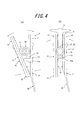
- A is a longitudinal cross-sectional view of the puncture assisting device shown in FIG. 1
- (b) is a cross-sectional view taken along line AA in FIG.
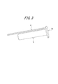
- It is a perspective view of the pusher of the syringe shown in FIG.
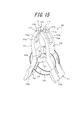
- It is a figure which shows the procedure which picks the skin of the elbow joint extension side part of an elbow with the puncture assistance apparatus shown in FIG. 1, (a) shows the state before picking up skin, (b) shows after picking up the skin .
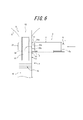
- FIG. 1 It is sectional drawing which shows a mode that a rod part is inserted in a rod insertion part, and a pair of clamping part is pushed open, (a) shows the state before inserting a rod part in a rod insertion part, (b) is a rod The state after inserting a rod part in an insertion part is shown. It is a perspective view which shows the modification of the rod part shown in FIG. It is a perspective view of the puncture assisting device which is the 2nd Embodiment of this invention, and the puncture assisting device and syringe which comprise a puncture device set. It is a figure which shows the procedure of picking the skin of the elbow joint extension side part of an elbow with the puncture assistance apparatus shown in FIG.
- FIG. 9 shows the state before picking skin, and (b) shows after skin is picked.
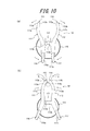
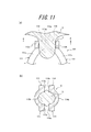
- (A) is sectional drawing which shows in detail the state of the skin of the elbow joint extension side part of the elbow picked by the clamping part
- (b) is sectional drawing which follows the BB line in the same figure (a).
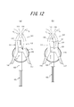
- It is a figure which shows the procedure which punctures the needle of a syringe to the skin picked up by the puncture assistance apparatus, (a) shows the state which set the syringe to the syringe insertion part, (b) punctured the skin of the syringe needle Indicates the state.
- FIG. 9 It is a figure which shows a mode that a pusher of a syringe is pushed and a chemical
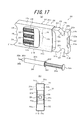
- FIG. 17 is a perspective view of the puncture auxiliary device and syringe which comprise the puncture device set which is another invention
- FIG. 17 is a side view of the puncture auxiliary device shown to (a).
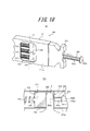
- FIG. 17 is a perspective view which shows the state which punctured the needle
- b) is the sectional drawing.
- FIG. 1 the first embodiment of the present invention will be described with reference to FIGS. 1 to 8.
- FIG. 1 the first embodiment of the present invention will be described with reference to FIGS. 1 to 8.
- a puncture device set 1 according to the first embodiment of the present invention shown in FIG. 1 is used to apply a drug such as a biologic agent to the elbow joint extension side of the elbow in various treatments such as rheumatoid arthritis and multiple sclerosis. It is used when injected subcutaneously into the skin.
- the puncture device set 1 includes a puncture assisting device 2 and a syringe 3. In the syringe 3, a pusher side rod portion 4 corresponding to the puncture assisting device 2 is provided on the pusher 5.
- the puncture assisting device 2 includes a first clamping piece 11 and a second clamping piece 12.
- the first sandwiching piece 11 and the second sandwiching piece 12 are each configured as a rectangular plate, and are combined in the thickness direction in an arrangement in which the outer shapes thereof are substantially matched.
- An intermediate portion in the longitudinal direction of the inner side surface of the second clamping piece 12 (the surface facing the first clamping piece 11 side) extends straight in the width direction and is also the inner side surface of the first clamping piece 11.
- a convex piece 12a that projects toward (the surface facing the second clamping piece 12) is integrally provided, and the inner surface of the first clamping piece 11 abuts on the upper surface of the convex piece 12a. ing.
- the upper surface of the convex piece portion 12a is curved in an arc shape when viewed from the side of the sandwiching pieces 11, 12, and the first sandwiching piece 11 is a second sandwiching piece with the upper surface of the convex piece portion 12a as a fulcrum. 12 can be rotated relative to 12.
- the first clamping piece 11 and the second clamping piece 12 can be made of, for example, a synthetic resin such as acrylic resin or ABS resin, but other materials such as a metal formed of a stainless steel plate, an aluminum alloy, or the like. It can also be formed by.
- a synthetic resin such as acrylic resin or ABS resin
- other materials such as a metal formed of a stainless steel plate, an aluminum alloy, or the like. It can also be formed by.
- first holding piece 11 and the second holding piece 12 are not limited to the configuration in which the first holding piece 12 and the second holding piece 12 are supported by the above-described convex piece portion 12a and combined with each other so as to be able to rotate relative to each other. It can also be set as the structure combined so that relative rotation is possible mutually using a moving mechanism.
- the portion on the tip side (the upper side in FIG. 1 and FIG. 2) of the first holding piece 11 that is in contact with the convex piece 12a is a plate-like first holding portion 13, and the second A portion of the sandwiching piece 12 on the front end side with respect to the convex piece portion 12 a serves as a plate-like second sandwiching portion 14 that faces the first sandwiching portion 13.
- the pair of sandwiching portions 13 and 14 can be opened and closed so that the first sandwiching piece 11 and the second sandwiching piece 12 relatively rotate, so that the distance between them approaches and separates.
- the 1st clamping part 13 and the 2nd clamping part 14 which open and close can pinch the said skin by closing in the state which pinched
- first sandwiching portion 13 and the second sandwiching portion 14 By opening the first sandwiching portion 13 and the second sandwiching portion 14, it is possible to open the skin that has been picked by these.
- slip with respect to the picked skin can be provided in the inner surface of each clamping part 13 and 14, respectively, for example, the four groove
- Such a first clamping part 13 and a second clamping part 14 constitute a skin collecting part G.
- the puncture assisting device 2 is provided with a leaf spring 15 as an urging portion.
- the first clamping part 13 and the second clamping part 14 are urged by the leaf spring 15 in a closing direction, that is, in a direction approaching each other, and are brought into contact with each other in a natural state.
- the 1st clamping part 13 and the 2nd clamping part 14 can also be comprised so that a predetermined space
- the leaf spring 15 is formed in a U-shape in which a first plate-like piece 15a and a second plate-like piece 15b are connected by a curved piece 15c.
- the outer surfaces of the first clamping piece 11 and the second clamping piece 12 are respectively provided with recesses 11a and 12b extending along the longitudinal direction, and the first plate-like piece 15a of the leaf spring 15 is the first clamping piece.
- the second plate-like piece 15b of the leaf spring 15 is arranged in the recess 12b provided in the second holding piece 12 and is secondly arranged. Are supported by the sandwiching portion 14.
- Through holes 11b and 12c that penetrate the sandwiching pieces 11 and 12 in the thickness direction are provided on the base end sides of the recesses 11a and 12b, respectively, and the curved piece 15c of the leaf spring 15 passes through these through holes 11b and 12c.
- the 1 plate-like piece 15a and the 2nd plate-like piece 15b are connected.
- a cylindrical locking portion 15d is integrally provided at the tip of the first plate-like piece 15a and the second plate-like piece 15b, and these locking portions 15d are provided on the bottom surfaces of the recesses 11a and 12b, respectively.
- the plate spring 15 for example, a metal plate spring formed of a steel plate such as spring steel or stainless steel can be used, but for example, a resin plate spring can also be used.
- the urging unit is not limited to the plate spring 15 having the above-described configuration, and the first clamping unit 13 and the second clamping unit 14 such as a string spring, a torsion spring, and an elastic material such as rubber. As long as they can be urged toward each other in a closing direction, other configurations can be adopted.
- the portion on the base end side (the side opposite to the side on which the first sandwiching portion 13 is provided) with respect to the portion of the first sandwiching piece 11 that abuts on the convex piece portion 12 a becomes the first opening knob 16.
- a portion closer to the base end side (the side opposite to the side where the second clamping portion 14 is provided) than the convex piece portion 12 a of the second clamping piece 12 is a second opening knob 17.
- the first opening knob 16 and the second opening knob 17 are opposed to each other with a space therebetween, for example,
- the first holding piece 11 and the second holding piece 12 are relatively rotated by picking the opening knobs 16 and 17 so as to be held between two fingers and operating them in a direction to bring them closer to each other.
- the pair of sandwiching portions 13 and 14 can be opened.
- the pair of clamping parts 13 and 14 are returned to the closed state by the spring force of the leaf spring 15. That is, by operating these opening knobs 16 and 17, the pair of holding parts 13 and 14 can be opened and closed.
- a non-slip configuration such as three ribs 16a and 17a extending in the width direction can be provided.
- the opening knobs 16 and 17 are pinched so as to be sandwiched between two fingers to open the pair of clamping parts 13 and 14, and in this state, the pair of clamping parts 13 , 14 is pressed against the skin of the elbow joint extension side of the elbow from the vertical direction, and then the operation of the release knobs 16, 17 is released to hold and hold the skin between the pair of clamping parts 13, 14. can do.
- a holding piece 18 extending in the longitudinal direction is integrally provided at the base end of the second holding piece 12.
- the holding piece 18 is formed in a plate shape thinner than the second holding piece 12 and is slightly inclined toward the outer surface side with respect to the second holding piece 12.
- a first puncture guide portion (syringe insertion portion) 21 is provided on the side portion of the first clamping portion 13, and a second puncture guide portion (syringe insertion portion) 22 is provided on the side portion of the second clamping portion 14. Is provided. These puncture guide portions 21 and 22 are formed in a ring shape having circular guide holes 21a and 22a, respectively, and the syringe 3 can be inserted into the guide holes 21a and 22a.
- the first puncture guide portion 21 has a posture in which the guide hole 21 a is directed between the first sandwiching portion 13 and the second sandwiching portion 14 so as to be integrated with the side portion of the first sandwiching portion 13.
- the second puncture guide portion 22 is provided such that its guide hole 22a is oriented between the first sandwiching portion 13 and the second sandwiching portion 14, and the side portion of the second sandwiching portion 14 is provided. Are integrally provided. The axial centers of the guide holes 21a and 22a of these two puncture guide portions 21 and 22 coincide when the pair of sandwiching portions 13 and 14 are closed so as to contact each other.
- a rod insertion part 23 is provided between the first clamping part 13 and the second clamping part 14.
- the rod insertion portion 23 is a region sandwiched between the convex piece portion 12 a and the puncture guide portions 21 and 22 between the first clamping portion 13 and the second clamping portion 14.
- the leaf spring 15 is provided between the first plate-like piece 15a and the second plate-like piece 15b and opens toward the sides of the first holding portion 13 and the second holding portion 14.
- the inclined surface 24 is chamfered between the inner side surface and the side surface of the first holding piece 11 and between the inner side surface and the side surface of the second holding piece 12. Yes.
- the rod insertion part 23 has a cross-sectional area at the inlet (opening end) larger than the cross-sectional area of the pusher side rod part 4 provided on the pusher 5 of the syringe 3, from the inlet side toward the inner side.
- the cross-sectional area gradually decreases, and the central portion has a shape that is a constant cross-sectional area smaller than the cross-sectional area of the pusher side rod portion 4.
- the distance between the holding part 14 and the inner side surface is smaller than the width dimension of the pusher side rod part 4 inserted into the rod insertion part 23. Therefore, when the pusher side rod portion 4 is inserted into the rod insertion portion 23, the distance between the pair of sandwiching portions 13 and 14 is gradually expanded by the pusher side rod portion 4 with the insertion.
- the syringe 3 includes an outer cylindrical body 31 and a needle 32 in addition to the pusher side rod portion 4 and the pusher 5 as the rod portions described above.
- the outer cylinder 31 is formed in a cylindrical shape having one end opened and the other end closed by a needle support portion 31a, and the inside is a storage chamber for storing a medicine.
- the pusher 5 is formed in a cylindrical shape having an outer diameter corresponding to the inner diameter of the outer cylindrical body 31, and is inserted into the inner end of the outer cylindrical body 31 so as to be relatively movable in the axial direction with respect to the outer cylindrical body 31. It is installed.
- the outer cylinder 31 and the pusher 5 can be made of resin or glass, for example. Further, the pusher 5 may be configured such that a seal member that is formed of an elastic body such as rubber and seals between the inner peripheral surface of the outer cylindrical body 31 is attached to the tip thereof.
- a cylindrical hub 31b having a smaller diameter than the needle support portion 31a is integrally provided at the axis of the needle support portion 31a, and the needle 32 is fixed to the hub 31b.
- the needle 32 is a hollow needle, and the needle tip 32a is cut obliquely and formed at an acute angle. Further, the needle 32 is fixed to the hub 31b at the base end portion, and the inner cavity portion communicates with the inside of the outer cylindrical body 31 via the hub 31b.
- hook 32 what was formed, for example with metal materials, such as stainless steel, an aluminum alloy, and a titanium alloy, can be used.
- the outer diameter of the needle support portion 31a of the syringe 3, that is, the outer diameter of the outer cylindrical body 31, is made larger than the inner diameter of the guide holes 21a, 22a of the puncture guide portions 21, 22, and the outer diameter of the hub 31b of the syringe 3 is punctured. It is made smaller than the internal diameter of the guide holes 21a and 22a of the guide parts 21 and 22. Therefore, the needle 32 and the hub 31b of the syringe 3 can be inserted into the guide holes 21a and 22a of the puncture guide portions 21 and 22 from the side of the puncture assisting device 2. Further, the needle support portion 31a abuts against the puncture guide portions 21 and 22, thereby restricting the insertion depth of the needle 32 and the hub 31b into the puncture guide portions 21 and 22, that is, the pair of sandwiching portions 13 and 14. Can do.
- a pair of finger flanges 31c extending toward the outer side in the radial direction are integrally provided at the opening end of the outer cylindrical body 31 in a symmetrical arrangement.
- a disc-shaped pushing flange 5a is integrally provided at the base end of the pusher 5. Accordingly, the index finger and the middle finger are hung on the pair of finger-hanging flanges 31c of the outer cylindrical body 31, and the thumb is pushed on the pushing flange 5a of the pusher 5, and the pusher 5 is directed toward the inside of the outer cylindrical body 31 with the thumb.
- the pusher side rod portion 4 is provided on the pusher 5. More specifically, the pusher side rod portion 4 is longer than the pusher 5 and is formed in a rod shape having a rectangular cross section, and is integrally connected to the lower surface of the pushing flange 5a of the pusher 5 at the base end thereof. Yes. Further, the pusher side rod portion 4 is arranged on the radially outer side of the pusher 5 with a space from the pusher 5 and arranged in parallel with the pusher 5 so as to extend along the axial direction of the pusher 5. Has been. The tip of the pusher side rod portion 4 can be formed into an acute angle shape by chamfering.
- the pusher side rod portion 4 is provided integrally with the pusher 5 as in this embodiment, it is preferable to form these by injection molding of a resin material.
- the pusher side rod portion 4 is not limited to the structure provided integrally with the pusher 5, and may be configured to be fixed to the pusher 5 by using, for example, a fastening member, an adhesive, or the like. it can.
- the rod portion is not limited to the pusher side rod portion 4 provided integrally with the pusher 5 of the syringe 3 as described above, and may be configured separately from the pusher 5. In this case, the rod portion can be operated independently from the operation of the pusher 5.
- a tunnel-like rod support portion 33 extending along the axial direction from the portion of the needle support portion 31a is integrally provided at a position shifted by 90 degrees with respect to the pair of finger flanges 31c on the outer peripheral surface of the outer cylindrical body 31. Yes.
- the pusher side rod portion 4 is inserted into the rod support portion 33, and the rod support portion 33 is slidably contacted with the outer surface of the pusher side rod portion 4 on its inner surface so that the pusher side rod portion 4 can slide freely. To support.
- a skin picking process is performed in which the skin S of the elbow joint extension side portion of the elbow is picked by the pair of sandwiching portions 13 and 14 of the puncture assisting device 2, that is, the skin collecting portion G.
- the pair of opening knobs 16 and 17 are picked so as to be sandwiched between, for example, two fingers, and the pair of holding parts 13 and 14 are opened.
- the inner surface of the second opening knob 17 is cut away so as to gradually become thinner toward the holding piece 18, and the first opening is opened when the pair of holding portions 13 and 14 are opened.
- the opening of the pair of holding portions 13 and 14 can be increased by making the inner knob 16 reach the notch portion of the knob portion 16.
- the pair of holding portions 13 and 14 are pressed against the skin S of the elbow joint extension side portion of the elbow from the vertical direction to release the operation force applied to the opening knobs 16 and 17.
- the skin S is picked and held between these sandwiching portions 13 and 14.
- the picked skin S is made to reach the site where the puncture guide portions 21 and 22 between the pair of sandwiching portions 13 and 14 are provided. Since the spring force is applied to the pair of sandwiching portions 13 and 14 from the leaf spring 15 in the direction of closing them, the skin S picked by the sandwiching portions 13 and 14 is pressed between the sandwiching portions 13 and 14. It is in a state.
- the pair of sandwiching portions 13 and 14 is placed in a posture perpendicular to the longitudinal direction of the arm to be subcutaneously injected, that is, the pair of sandwiching portions 13 and 14 is the arm. It is preferable to pick the skin S as a posture aligned along the longitudinal direction.
- the puncture guide portions 21 and 22 faces the side of the extended arm, and the puncture guide portion 21 of the syringe 3 to be described later. , 22 and skin S can be easily punctured.
- the gathering step of gathering the skin S of the elbow joint extension side part of the elbow so as to have a shape that is easier to pick before the skin picking step.
- the gathering step for example, the skin S is picked between the pair of holding portions 13 and 14 by the same operation as the skin picking step, the picked skin S is once separated, and the holding portions 13 and 14 are opened again.
- it can be performed by a method of picking a wide range of skin S.
- an adhesive material or a concavo-convex shape may be provided at the tip of each of the pair of sandwiching portions 13 and 14 so that the skin S can be collected more easily.
- the gathering step is not limited to the above method, and can be performed by a method of gathering the skin S by hand without using the puncture assisting device 2 or a method of gathering the skin S using another device.
- the skin S picked by the sandwiching portions 13 and 14 can be tensioned by pulling the holding piece 18 as necessary.
- the syringe 3 is set in either one of the puncture guide portions 21 and 22 as a syringe setting step.
- the needle 32 of the syringe 3 is inserted into the guide hole 22a of the puncture guide portion 22 from the side of the puncture assisting device 2.
- the syringe 3 is set on the puncture guide portion 22.
- the syringe 3 is set to a posture in which the tip of the pusher side rod portion 4 faces the open end of the rod insertion portion 23.
- the syringe 3 set in the puncture guide portion 22 is pinched between the pair of sandwiching portions 13 and 14, that is, by the sandwiching portions 13 and 14.
- the needle 32 of the syringe 3 is punctured into the skin S. Accordingly, the needle 32 is sandwiched between the pair of sandwiching portions 13 and 14 in parallel with the sandwiching portions 13 and 14 and from the side of the sandwiching portions 13 and 14, that is, the skin S picked by the sandwiching portions 13 and 14.
- the skin S is punctured from the side of the.
- the insertion amount of the syringe 3 into the puncture guide portion 22 is determined by the needle support portion 31a.
- the contact with the puncture guide unit 22 is restricted to a predetermined range.
- the puncture depth to the skin S of the needle 32 is prescribed
- the pusher side rod portion 4 protrudes from the rod support portion 33 together with the pusher 5 and is inserted into the rod insertion portion 23.
- the height dimension of the pusher side rod portion 4 in the vertical direction in the drawing is larger than the vertical distance between the inner side surfaces of the pair of sandwiching portions 13 and 14 when the skin S is picked. Is also getting bigger.
- the sandwiching portions 13 and 14 for grasping the skin S while injecting the drug from the needle 32 of the syringe 3 into the skin S stably picked between the pair of sandwiching portions 13 and 14 of the puncture assisting device 2.
- the pusher side rod portion 4 may have a configuration in which a tapered tip portion 4 a is provided on the tip side.
- the tapered tip portion 4a has a shape in which the cross-sectional area gradually decreases toward the tip side.
- tip part 4a can also be applied with respect to the structure which provided the inclined surface 24 in a pair of clamping parts 13 and 14. FIG. By adjusting the taper angle of the tapered distal end portion 4a, the distance between the pair of sandwiching portions 13 and 14 can be gradually widened at an appropriate timing or degree with respect to the amount of drug injected.
- a needle removal step of pulling out the syringe 3 from the puncture guide portion 22 and removing the needle 32 of the syringe 3 from the skin S is performed.
- the medicine is injected from the needle 32 of the syringe 3 into the skin S stably picked between the pair of holding parts 13, 14 of the puncture assisting device 2, the pusher side rod part 4
- the releasing step of releasing the force of the pair of clamping parts 13 and 14 that grip the skin S can be omitted.
- the skin S into which the medicine has been injected by the syringe 3 is released from the state of being picked by the holding portions 13 and 14 of the puncture assisting device 2, and the administration of the medicine is completed.
- the skin S of the elbow joint extension side portion of the elbow is stably picked by the puncture assisting device 2 and is picked by the puncture assisting device 2.
- the drug can be administered into the skin S by puncturing the needle 32 of the syringe 3 from the side. Therefore, the puncture assisting device 2 is operated with one hand to pick the skin S of the elbow joint extension side of the other arm, and then the syringe 3 is held with one hand from which the puncture assisting device 2 is released, and the puncture is performed.
- the elbow joint extension side portion of the elbow can be easily and safely injected into the skin S.
- the needle 32 of the syringe 3 can be safely punctured into the skin S without damaging the nerve.
- the puncture device set 101 or the puncture assisting device 102 according to the second embodiment of the present invention shown in FIG. 9 is used in various treatments such as rheumatoid arthritis and multiple sclerosis. It is used when injecting subcutaneously into the skin of the elbow joint extension side.
- This puncture device set 101 includes a puncture assist device 102 and a syringe 103.
- a commercially available general syringe can be used as a syringe for subcutaneous injection.
- the puncture assisting device 102 includes a first holding piece 111 and a second holding piece 112.
- the first clamping piece 111 and the second clamping piece 112 can be made of, for example, a synthetic resin such as acrylic resin or ABS resin, but other materials such as a metal formed of a stainless steel plate, an aluminum alloy, or the like. It can also be formed by.
- a synthetic resin such as acrylic resin or ABS resin
- other materials such as a metal formed of a stainless steel plate, an aluminum alloy, or the like. It can also be formed by.
- a pair of legs 111a is provided on the tip side (upper side in FIG. 9) of the first clamping piece 111. Each of these leg portions 111a has a shape curved outward so as to widen the interval with the second sandwiching piece 112, and is arranged side by side with a space therebetween. Similarly, a pair of leg portions 112a is provided on the distal end side (the upper side in FIG. 9) of the second holding piece 112. Each of these leg portions 112a has a shape curved outward so as to widen the interval with the first sandwiching piece 111, and is arranged side by side with a space therebetween.
- the first sandwiching piece 111 and the second sandwiching piece 112 have a substantially symmetrical shape, and are combined with each other in an arrangement in which their outer shapes are substantially matched.
- a pair of hinge pieces 111b protrudes inward and is integrally provided at an intermediate portion in the longitudinal direction of the inner side surface of the first holding piece 111 (the surface facing the second holding piece 112).
- a pair of hinge pieces 112b project inward and are integrally provided at an intermediate portion in the longitudinal direction of the inner side surface of the piece 112 (the surface facing the first sandwiching piece 111).
- the pair of hinge pieces 111b of the first holding piece 111 are disposed so as to overlap each other inside the pair of hinge pieces 112b of the corresponding second holding piece 112, and are relatively relative to the hinge piece 112b by a pin portion (not shown). Is pivotally connected to the motor. That is, the first holding piece 111 can rotate relative to the second holding piece 112 around the pin portions of the hinge pieces 111b and 112b.
- the first sandwiching piece 111 and the second sandwiching piece 112 are not limited to be configured to be relatively rotatable with each other by the hinge pieces 111b and 112b, but can be relatively rotated with each other using another rotating mechanism. It can also be set as the structure combined.
- a first sandwiching portion 113 is provided at the tip of each of the pair of leg portions 111a of the first sandwiching piece 111, and a second portion of each of the pair of leg portions 112a of the second sandwiching piece 112 is provided at the tip. Is provided.
- One of the first holding portions 113 is arranged to face the second holding portion 114 so that the flat holding surface 113a faces the flat holding surface 114a of the one second holding portion 114.
- one first clamping part 113 faces the second clamping part 114 so that the flat clamping surface 113a faces the flat clamping surface 114a of the other second clamping part 114.
- the pair of first sandwiching portions 113 and the pair of second sandwiching portions 114 are not limited to the above-described arrangement, and for example, the first sandwiching portion 113 and the second sandwiching portion 114 that are disposed diagonally opposite each other. However, it is also possible to adopt a configuration in which the shapes are symmetrical with respect to the center position of the four sandwiching portions 113 and 114. In this case, the sandwiching surface 113a of the first sandwiching portion 113 and the sandwiching surface 114a of the second sandwiching portion 114 that are disposed obliquely opposite to each other face each other in parallel and are disposed obliquely to each other.
- the clamping surfaces 113a and 114a of the two clamping parts 113 and 114 face each other in parallel.
- the skin S can be stabilized more stably so that each of the four clamping surfaces 113a and 114a of each clamping part 113 and 114 faces the center position of the four clamping parts 113 and 114. Can be picked.
- sandwiching portions 113 and 114 are provided, and it is possible to provide four or more sandwiching portions. Regardless of the number of the sandwiching portions, it is preferable that all the sandwiching portions are arranged side by side in an annular shape centering on these center positions.
- the pair of sandwiching portions 113 and the pair of sandwiching portions 114 can be opened and closed so that the first sandwiching piece 111 and the second sandwiching piece 112 rotate relative to each other so as to approach and separate from each other.
- the 1st clamping part 113 and the 2nd clamping part 114 which open and close can pinch the said skin S by closing in the state which pinched
- the skin S picked by these can be open
- the 1st clamping part 113 and the 2nd clamping part 114 which were combined together so that opening and closing were possible comprised the skin collection part G which collects and picks up the skin S.
- the pair of sandwiching portions 113 provided on the first sandwiching piece 111 are connected to each other by an arc-shaped first arch portion 113b provided integrally therebetween.
- the pair of sandwiching portions 114 provided in the second sandwiching piece 112 are connected to each other by an arc-shaped second arch portion 114b provided integrally therewith.
- These arch portions 113b and 114b are curved in directions in which the distance between them is increased.
- the puncture assisting device 102 is provided with a pair of C-shaped springs 115 as urging portions.
- the first sandwiching piece 111 is provided with a pair of slit-like through holes 111c for spring insertion
- the second sandwiching piece 112 is provided with a pair of slit-like through holes 112c for spring insertion.
- Each of the pair of C-shaped springs 115 has a shape in which, for example, a spring steel or stainless steel wire is curved into a C shape, and is inserted into the corresponding through holes 111c and 112c, respectively, and one end thereof is the first. The other end is supported on the outer surface of the second sandwiching piece 112.
- the first clamping part 113 and the second clamping part 114 are urged by the pair of C-shaped springs 115 in the closing direction, that is, in the direction of approaching each other.
- the C-shaped spring 115 is not limited to the above-described spring steel or stainless steel, and may be a resin spring or the like. Further, the urging portion is not limited to the C-shaped spring 115 having the above-described configuration, and the first clamping portion 113 and the second clamping portion such as those using elastic materials such as a string spring, a torsion spring, and rubber are used. Any other configuration can be used as long as it can bias 114 in the direction of closing each other.
- a portion of the first holding piece 111 closer to the base end side than the hinge piece 112b (the side opposite to the side where the first holding portion 113 is provided) serves as a first opening knob 116
- a portion of the holding piece 112 closer to the base end side than the hinge piece 112b (the side opposite to the side where the second holding portion 114 is provided) is a second opening knob 117.
- the first opening knob 116 and the second opening knob 117 are opposed to each other with a space therebetween, for example,
- the first clamping piece 111 and the second clamping piece 112 are relatively rotated by operating the knobs for opening 116, 117 so as to be sandwiched between two fingers and operating them in a direction to bring them closer to each other.
- the pair of sandwiching portions 113 and 114 can be opened.
- the operation of the opening knobs 116 and 117 is released, the pair of holding portions 113 and 114 are returned to the closed state by the spring force of the C-shaped spring 115. That is, the pair of holding portions 113 and 114 can be opened and closed by operating these opening knobs 116 and 117.
- the opening knobs 116 and 117 may be configured so that finger hooks 116a and 117a are integrally provided side by side.
- the finger hooks 116a and 117a are formed in a slightly warped plate shape so as to protrude inward.
- the pair of holding portions 113 and 114 are opened by holding the opening knobs 116 and 117 so that the fingers are sandwiched between the fingers.
- the skin S is picked and held between the pair of clamping parts 113, 114. be able to.
- a syringe insertion part 121 is provided between the first clamping parts 113 and 114 and the opening knobs 116 and 117.
- the syringe insertion portion 121 is disposed inside the hinge pieces 111 b and 112 b and is fixed to either the inner side surface of the first holding piece 111 or the inner side surface of the second holding piece 112.
- the syringe insertion portion 121 is formed in a cylindrical shape having an insertion hole 121a at its axis, and the syringe 103 can be inserted into the insertion hole 121a. Moreover, the syringe insertion part 121 can hold
- the syringe insertion portion 121 has a posture in which the insertion hole 121a opens toward the center position of the four sandwiching portions 113 and 114, that is, a posture in which the axis of the insertion hole 121a passes through the center position of the four sandwiching portions 113 and 114. Is provided.
- the syringe 103 inserted into the insertion hole 121a of the syringe insertion portion 121 has a posture in which the needle 132 is directed to the center position of the four holding portions 113 and 114, that is, the central axis of these four holding portions 113 and 114. It is assumed that the posture is along the direction.
- the center position of the four sandwiching portions 113 and 114 is the skin collecting portion G.
- the reference position of these four sandwiching portions 113 and 114 (for example, the center of gravity of the sandwiching surfaces 113a and 114a) is a straight line. It is best to insert the needle 132 at the position of the center of gravity of the quadrilateral formed by tying.
- the syringe insertion part 121 may be inclined at the tip of the insertion hole 121a so that the insertion hole 121a faces the center position when the opening knob 116 is opened. Moreover, the syringe insertion part 121 can also be set as the structure provided integrally with the 1st clamping piece 111 or the 2nd clamping piece 112. FIG. Further, when the syringe insertion portion 121 has both the hinge pieces 111b and 112b and the syringe insertion portion 121 penetrating through the hinge pins, the opening knobs 116 and 117 are both in the opened state and the closed state. It can also be configured to always face the center position.
- the syringe in order to prevent the syringe insertion part 121 from rotating around the hinge pin part when the syringe is inserted or when a liquid medicine is injected, the syringe is provided with at least two clamping pieces and an elastic piece among the four clamping parts 113 and 114. It can also be set as the structure which hold
- the syringe 103 includes a pusher 105, an outer cylinder 131, and a needle 132.
- the outer diameter of the portion of the outer cylinder 131 of the syringe 103 close to the needle 132 is slightly smaller than the inner diameter of the insertion hole 121a of the syringe insertion portion 121. Therefore, the syringe 103 can be inserted into the insertion hole 121a of the syringe insertion portion 121.
- a stopper or the like is provided on the outer cylinder 131 of the syringe 103 to regulate the insertion depth of the syringe insertion portion 121 of the syringe 103 into the insertion hole 121a, that is, the puncture depth of the needle 132 of the syringe 103 into the skin S. It can also be set as the structure to do.
- an annular finger-hanging flange 131c that extends outward in the radial direction is integrally provided at the open end of the outer cylinder 131.
- a disc-shaped pushing flange 105 a is integrally provided at the base end of the pusher 105.
- a skin picking process is performed in which the skin S of the elbow joint extension side portion of the elbow is picked by the pair of holding portions 113, 114, that is, the skin collecting portion G of the puncture assisting device 102.
- the pair of opening knobs 116 and 117 and the finger hooks 116a and 117a are picked so as to be pinched with, for example, fingers, and the pair of holding parts 113 and 114 are opened. .
- the pair of holding parts 113 and 114 are pressed against the skin S of the elbow joint extension side part of the elbow from the vertical direction, and the operating force applied to the opening knobs 116 and 117 and the finger hooks 116a and 117a is applied.
- the skin S is picked and held between the sandwiching portions 113 and 114. Since the spring force is applied to the pair of sandwiching portions 113 and 114 from the C-shaped spring 115 in a direction to close them, the skin S picked by the sandwiching portions 113 and 114 is compressed between the sandwiching portions 113 and 114. It is in the state.
- the skin S is picked from the four directions by the four sandwiching portions 113 and 114, and therefore the skin S of the picked portion is substantially cylindrical.
- the pair of first holding parts 113 are connected by the first arch part 113b and the pair of second holding parts 114 are connected by the second arch part 114b, four holding parts Part of the skin S picked by the parts 113 and 114 is sandwiched between the arch parts 113b and 114b, so that the skin S can be picked more reliably in a columnar shape.
- the skin S picked by the puncture assisting device 102 in the skin picking process protrudes from the elbow surface in a vertical column shape.
- the skin S of the elbow joint extension side portion of the elbow is gathered together so that it can be easily picked up. Can also be done.
- the gathering step for example, the skin S is picked between the pair of holding portions 113 and 114 by the same operation as the skin picking step, the picked skin S is released once, and the holding portions 113 and 114 are opened again.
- it can be performed by a method of picking a wide range of skin S.
- an adhesive material or a concavo-convex shape may be provided at the distal ends of the pair of sandwiching portions 113 and the pair of sandwiching portions 114 so that the skin S can be more easily collected.
- the gathering step is not limited to the above method, and can be performed by a method of gathering the skin S by hand without using the puncture assisting device 102 or a method of gathering the skin S using another device.
- the syringe 103 is then inserted into the insertion hole 121a of the syringe insertion portion 121 as a syringe setting step.
- the syringe setting step the syringe 103 is placed on the skin S on the elbow joint extension side of the elbow from the side where the opening knobs 116, 117 of the puncture assisting device 102 are provided.
- the syringe insertion portion 121 is set.
- the syringe 103 set in the syringe insertion portion 121 is directed between the four sandwiching portions 113 and 114 along the syringe insertion portion 121. That is, the needle 132 is pushed toward the skin S picked by the sandwiching portions 113 and 114, and the needle 132 is punctured into the skin S from a direction perpendicular to the columnar skin S at the center position of the four sandwiching portions 113 and 114. As described above, the needle 132 of the syringe 103 is punctured into the skin S along the central axis passing through the central positions of the four holding portions 113 and 114. When the needle 132 is punctured perpendicularly to the skin S, the nerve through which the needle 132 passes can be reduced, and pain due to puncture can be reduced.
- the needle 132 of the syringe 103 is inserted into the skin S.
- the puncture depth can be defined (puncture depth defining step). Therefore, the needle 132 of the syringe 103 can be prevented from being punctured too deeply into the skin S.
- a needle removal step of pulling out the syringe 103 from the syringe insertion portion 121 and removing the needle 132 of the syringe 103 from the skin S is performed.
- the pair of opening knobs 116 and 117 and the finger hooks 116a and 117a are pinched with fingers to release the force of the four clamping parts 113 and 114 that are holding the skin S.
- a release process is performed. Thereby, the skin S into which the medicine has been injected by the syringe 103 is released from the state of being picked by the holding portions 113 and 114 of the puncture assisting device 102.
- the release process may be performed before the needle removal process. In this case, when the puncture assisting device 102 is moved away from the elbow joint extension side of the elbow, the needle 132 is naturally removed. Is called. *
- the skin S on the elbow joint extension side portion of the elbow is stably picked by the puncture assisting device 102, and the skin S is picked by the puncture assisting device 102.
- the needle 132 of the syringe 103 can be punctured from the vertical direction to administer the drug into the skin S. Accordingly, the puncture assisting device 102 is operated with one hand to pick up the skin S of the elbow joint extension side of the other arm, and then the syringe 103 held with the one hand with the puncture assisting device 102 separated is the syringe.
- the skin S of the elbow joint extension side part of the elbow is self-developed. Subcutaneous injection can be easily and safely performed.
- the needle 132 of the syringe 103 can be safely punctured into the skin S without damaging the nerve.
- a syringe setting step for setting the syringe 103 on the puncture assisting device 102 is performed.
- the needle S of the syringe 103 is punctured into the picked skin S by picking the skin S of the elbow joint extension side of the elbow with the four holding parts 113, 114. It can also be set as the structure which performs a puncture process.
- the syringe 103 since the syringe 103 is set in advance at a predetermined position of the syringe insertion portion 121, the skin S sandwiched between the four sandwiching portions 113, 114 gradually rises in a columnar shape and the four sandwiching portions 113 , 114 is automatically punctured into the skin S in the process of being picked. Therefore, the needle 132 of the syringe 103 can be easily attached to the skin S by a simple operation by simply setting the syringe 103 in the syringe insertion portion 121 of the puncture assisting device 102 and pinching the skin S with the four clamping portions 113 and 114 from the vertical direction. Can be punctured.
- the drug injection step, the release step, and the needle removal step are performed.
- the needle removal step the skin S is picked by the release step 4 The force of the two clamping portions 113 and 114 is released, and the skin S is automatically held away from the needle 132 when the skin S is not held in a cylindrical shape.
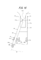
- FIG. 15 is a perspective view showing a modification of the puncture assisting device shown in FIG. 9, and FIG. 16 is a diagram for explaining the arrangement of the syringe insertion portion in the puncture assisting device shown in FIG.
- the syringe insertion portion 121 is not limited to the configuration arranged inside the hinge pieces 111b and 112b, but may be arranged outside the hinge pieces 111b and 112b. Even in this case, the syringe insertion portion 121 has a posture in which the insertion hole 121a opens toward the center position of the four sandwiching portions 113 and 114, that is, the axis of the insertion hole 121a is located between the four sandwiching portions 113 and 114. It is provided in a posture that passes through the center position.
- the syringe insertion portion 121 is in a posture in which the axial direction of the insertion hole 121a is deviated by 25 degrees with respect to the central axis L passing through the central positions of the four sandwiching portions 113 and 114.
- the skin S of the elbow joint extension side portion of the elbow is picked as a posture in which the first holding portion 113 and the second holding portion 114 are aligned along the longitudinal direction of the arm.
- assistance apparatus 102 can be inclined toward the inner side of a body, and the insertion operation to the syringe insertion part 121 of the syringe 103 can be made easy.
- Fig. 17 (a) is a perspective view of a puncture assisting device and a syringe constituting a puncture device set according to another invention
- Fig. 17 (b) is a side view of the puncture assisting device shown in Fig. 17 (a).
- 18 (a) is a perspective view showing a state where the needle of the syringe is punctured into the skin picked up by the puncture assisting device shown in FIG. 17, and
- FIG. 18 (b) is a sectional view thereof.
- the puncture device set 201 shown in FIG. 17 will be described.
- a space forming process for creating a skin placement space 230 for placing the skin S of the elbow joint extension side of the elbow is performed on the puncture assisting device 202.
- a thumb is put on the end face 212b of the inner gripping body 212, the inner gripping body 212 is pushed toward the inner side of the outer gripping body 211 with the thumb, and provided on the closing wall 211e of the outer gripping body 211.
- the index finger, the middle finger, and the ring finger are put on the finger-holding recess 215, and the outer gripping body 211 is pushed toward the inner gripping body 212 with these fingers.
- the inner gripping body 212 is moved to the open position with respect to the outer gripping body 211 against the spring 213, and the first opening 218 and the second opening 221 overlap the puncture assisting device 202.
- a skin placement space 230 can be created.
- any finger can be placed on the closing wall 211e of the outer gripping body 211 and the end surface 212b of the inner gripping body 212, but a thumb is placed on the end surface 212b of the inner gripping body 212 to By placing another finger on 211e, when this puncture assisting device 202 is opposed to the skin S of the elbow joint extension side of the elbow, the syringe insertion portion 223 can be directed to the front side of the body.
- a pressing process is performed in which the puncture assisting device 202 in a state where the skin placement space 230 is formed is pressed against the skin S on the elbow joint extension side of the elbow in a state where the arm is straightened.
- the side wall 211a of the outer gripping body 211 of the puncture assisting device 202 is pressed against the skin S of the elbow joint extension side part, and this skin S is applied to the first opening 218 and the second opening 221. It is placed inside, that is, inside the skin placement space 230.
- the side wall 211a of the outer gripping body 211 is formed in a concave surface curved inwardly, the side wall 211a is fitted to the surface on the elbow joint extension side of the elbow, so that more elbow joints of the elbow joint are extended.
- the side skin S can be placed inside the skin placement space 230.
- a skin picking step is performed in which the skin S placed in the skin placement space 230 is picked between the first holding part 219 and the second holding part 222.
- the outer gripping body 211 is pressed with the side wall 211a of the outer gripping body 211 of the puncture assisting device 202 against the skin S of the elbow joint extension side of the elbow and the skin S is placed in the skin placement space 230.
- the inner gripping body 212 is moved toward the closed position by the spring force of the spring 213.
- positioning space 230 can be picked between the 1st clamping part 219 and the 2nd clamping part 222 which move to the direction which mutually approaches.
- the picked skin S is made to reach the part where the needle insertion part 220 of the first clamping part 219 is provided. Since the spring force of the spring 213 is applied to the first clamping part 219 and the second clamping part 222 in the closing direction, the skin S is held in a state of being pinched between the clamping parts 219 and 222. .
- the outer gripping body 211 and the inner gripping body 212 combined in a sliding manner as described above are provided with holding portions 219 and 222, respectively, and the structure in which the skin S is pinched between the holding portions 219 and 222 is simplified.
- the skin S can be reliably picked by the operation.
- the elbow joint of the elbow It is also possible to perform a gathering process in which the skin S on the stretched side portion is gathered so as to have a shape that is easier to be placed inside the skin placement space 230 (a shape that is easier to pick).
- the gathering step for example, the skin S is picked between the pair of holding portions 219 and 222 by the same operation as the skin picking step, the picked skin S is once separated, and then the pair of holding portions 219 and 222 are again connected. It can be performed by reopening and picking a wider range of skin S.
- an adhesive material or a concavo-convex shape may be provided at the tip of each of the pair of sandwiching portions 219 and 222 so that the skin S can be collected more easily.
- the gathering step is not limited to the above method, and can be performed by a method of gathering the skin S by hand without using the puncture assisting device 202 or a method of gathering the skin S using another device.
- a puncture step is performed next.
- the puncturing step as shown in FIG. 18A, the syringe 203 is inserted from the syringe insertion portion 223 provided in the inner gripping body 212.
- the injection direction of the syringe 203 is defined by the syringe insertion portion 223 when the outer peripheral surface of the outer cylinder 203b is in sliding contact with the inner surface of the syringe insertion portion 223.
- the syringe insertion part 223 is directed to the front side of the body, and the opening end of the syringe insertion part 223 is tapered by a pair of inclined surfaces 223a, so that the syringe to the syringe insertion part 223
- the operation of inserting 203 is easy.
- the needle 203a is inserted into the needle insertion portion 220, and between the first clamping portion 219 and the second clamping portion 222.
- the needle 203a is punctured from the side of the skin S of the elbow joint extension side of the picked elbow.
- the outer cylinder 203b of the syringe 203 is guided by the syringe insertion portion 223 and the hub 203e is guided by the needle insertion portion 220, it is easy to insert the syringe 203 into the syringe insertion portion 223.
- the needle 203a of the syringe 203 can be easily and accurately punctured to a predetermined site of the skin S.
- the needle support portion 203d of the syringe 203 comes into contact with the tip of the needle insertion portion 220, whereby the puncture depth of the needle 203a of the syringe 203 into the skin S is regulated to a predetermined depth (puncture depth).
- the regulation process Therefore, the needle 203a of the syringe 203 can be prevented from being excessively deeply punctured into the skin S or penetrated through the skin S.
- a drug injection step is performed next.
- the medicine injection process the medicine 203 is injected into the skin S from the needle 203a of the syringe 203 by pushing the pusher 203c of the syringe 203 toward the needle 203a.
- the forefinger and the middle finger are put on the constricted portions 224 provided on both side surfaces 212c and 212d of the inner gripping body 212, the thumb is put on the pushing flange 203g of the pusher 203c, and the pusher 203c is attached to the outer cylinder with the thumb.
- an opening process of releasing the skin S of the elbow joint extension side of the elbow picked between the first holding part 219 and the second holding part 222 is performed.
- the inner gripping body 212 is pushed with the thumb and the outer gripping body 211 is pushed with another finger, and the inner gripping body 212 is moved to the open position against the spring 213.
- the first clamping part 219 and the second clamping part 222 move in a direction away from each other, and the first opening part 218 and the second opening part 221 are opened, and the first clamping part 219 and the first clamping part 219 2
- the skin S of the elbow joint extension side of the elbow picked between the sandwiching portions 222 is released.
- the needle 203a punctured in the skin S is removed from the skin S.
- the administration of the drug is completed by releasing the skin S of the elbow joint extension side of the elbow from the puncture assisting device 202.
- the needle 203 is pulled out from the syringe insertion part 223 and the needle 203a of the syringe 203 is removed from the skin S. You may make it perform a process.
- the skin S of the elbow joint extension side portion of the elbow can be easily and stably picked by the puncture assisting device 202, and the syringe 203 from the syringe insertion portion 223 provided in the puncture assisting device 202.
- the needle 203a of the syringe 203 is punctured into the skin S picked between the pair of holding portions 219 and 222 of the puncture assisting device 202, and the drug is easily administered to the skin S by a simple operation of simply inserting the needle. be able to.
- the puncture assisting device 202 is operated with one hand to pick the skin S of the elbow joint extension side of the other arm, and then the syringe 203 is held with one hand from which the puncture assisting device 202 is released.
- the needle 203a of the syringe 203 is punctured into the skin S picked between the pair of sandwiching portions 219 and 222, and the elbow joint of the elbow is extended with one hand by itself. Subcutaneous injection into the side skin S can be performed easily and safely.
- reference numeral 203f is a flange of the syringe 203
- reference numerals 211b to 211d are side walls of the outer gripping body 211
- reference numeral 212a is a side surface of the inner gripping body 212
- reference numeral 212e is a tip surface of the inner gripping body 212
- Reference numeral 214 denotes an assembly port of the outer gripping body 211
- reference numeral 224a denotes a holding surface of the constricted portion 224
- reference numeral 224b denotes an inclined surface of the constricted portion 224.
- the puncture device set 1, 101, 201 is used when the skin S other than the elbow skin is picked and injected subcutaneously is shown, but also when the puncture device set 1, 101, 201 is subcutaneously injected into other parts of the body Puncture device sets 1 and 101 of the present embodiment can be used.
Landscapes
- Health & Medical Sciences (AREA)
- Vascular Medicine (AREA)
- Engineering & Computer Science (AREA)
- Anesthesiology (AREA)
- Biomedical Technology (AREA)
- Heart & Thoracic Surgery (AREA)
- Hematology (AREA)
- Life Sciences & Earth Sciences (AREA)
- Animal Behavior & Ethology (AREA)
- General Health & Medical Sciences (AREA)
- Public Health (AREA)
- Veterinary Medicine (AREA)
- Dermatology (AREA)
- Infusion, Injection, And Reservoir Apparatuses (AREA)
Abstract
Description
2 穿刺補助器具
3 注射器
4 押し子サイドロッド部
4a テーパ状先端部
5 押し子
5a 押し込み用フランジ
11 第1の挟持片
11a 凹部
11b 貫通孔
11c 係止溝
12 第2の挟持片
12a 凸片部
12b 凹部
12c 貫通孔
12d 係止溝
13 第1の挟持部
13a 溝
14 第2の挟持部
14a 溝
15 板バネ(付勢部)
15a 第1板状片
15b 第2板状片
15c 湾曲片
15d 係止部
16 第1の開放用摘み部
16a リブ
17 第2の開放用摘み部
17a リブ
18 保持片
18a 孔
21 第1の穿刺ガイド部
21a ガイド孔
22 第2の穿刺ガイド部
22a ガイド孔
23 ロッド挿入部
24 傾斜面
31 外筒体
31a 針支持部
31b ハブ
31c 指掛けフランジ
32 針
32a 針先
33 ロッド支持部
101 穿刺器具セット
102 穿刺補助器具
103 注射器
105 押し子
105a 押し込み用フランジ
111 第1の挟持片
111a 脚部
111b ヒンジ片
111c 貫通孔
112 第2の挟持片
112a 脚部
112b ヒンジ片
112c 貫通孔
113 第1の挟持部
113a 挟持面
113b 第1のアーチ部
114 第2の挟持部
114a 挟持面
114b 第2のアーチ部
115 C形バネ
116 第1の開放用摘み部
116a 指掛け部
117 第2の開放用摘み部
117a 指掛け部
121 注射器挿入部
121a 挿入孔
131 外筒体
131c 指掛けフランジ
132 針
132a 針先
201 穿刺器具セット
202 穿刺補助器具
203 注射器
203a 針
203b 外筒体
203c 押し子
203d 針支持部
203e ハブ
203f 係止フランジ
203g 押し込み用フランジ
211 外把持体
211a~211d 側壁
211e 閉塞壁
212 内把持体
212a、212c、212d 側面
212b 端面
212e 先端面
213 スプリング
214 組付け口
215 凹部
218 第1開口部
219 第1挟持部
220 針挿通部
221 第2開口部
222 第2挟持部
223 注射器挿入部
223a 傾斜面
224 括れ部
224a 保持面
224b 傾斜面
230 皮膚配置スペース
S 皮膚
G 集皮部
Claims (8)
- 互いに対向し且つ開閉自在に組み合わされる一対の板状の挟持部と、
一対の前記挟持部を互いに閉じる方向に付勢する付勢部と、
一対の前記挟持部を互いに開く方向に操作可能な一対の開放用摘み部と、
一対の前記挟持部の間に設けられ、一対の前記挟持部の間隔を押し広げるロッド部が挿入されるロッド挿入部と、を有することを特徴とする穿刺補助器具。 - 前記付勢部は、一方の前記挟持部に支持される第1板状片、他方の前記挟持部に支持される第2板状片および前記第1板状片と前記第2板状片とを連ねる湾曲片を備えたU字形状の板バネであり、前記第1板状片と前記第2板状片との間に前記ロッド挿入部が設けられていることを特徴とする、請求項1に記載の穿刺補助器具。
- 前記ロッド挿入部は、その断面積が、前記ロッド部の断面積よりも小さい部分を有することを特徴とする、請求項1または2に記載の穿刺補助器具。
- 前記ロッド挿入部が、その断面積が入口側から内部側に向けて徐々に小さくなる部分を有し、前記ロッド部が前記ロッド挿入部に挿入されるに連れて一対の前記挟持部の間隔が徐々に押し広げられることを特徴とする、請求項3に記載の穿刺補助器具。
- 少なくとも一方の前記挟持部の側部に、注射器の針が挿通される穿刺ガイド部が設けられていることを特徴とする、請求項1~4の何れか1項に記載の穿刺補助器具。
- 前記穿刺ガイド部が、前記注射器の針支持部の外径よりも小さい内径のガイド孔を備えたリング状に形成されていることを特徴とする、請求項5に記載の穿刺補助器具。
- 請求項1~6の何れか1項に記載の穿刺補助器具と、
前記ロッド部が押し子に設けられた注射器と、を有することを特徴とする穿刺器具セット。 - 前記ロッド部は、その断面積が先端に向けて徐々に小さくなる形状に形成され、前記ロッド挿入部に挿入されるに連れて一対の前記挟持部の間隔を徐々に押し広げることを特徴とする、請求項7に記載の穿刺器具セット。
Priority Applications (3)
| Application Number | Priority Date | Filing Date | Title |
|---|---|---|---|
| EP15742569.5A EP3100756A4 (en) | 2014-01-31 | 2015-01-30 | Puncture aid and puncture instrument set |
| JP2015559831A JP6404837B2 (ja) | 2014-01-31 | 2015-01-30 | 穿刺補助器具および穿刺器具セット |
| US15/223,625 US10238815B2 (en) | 2014-01-31 | 2016-07-29 | Puncture assisting device and puncture device set |
Applications Claiming Priority (2)
| Application Number | Priority Date | Filing Date | Title |
|---|---|---|---|
| JP2014017831 | 2014-01-31 | ||
| JP2014-017831 | 2014-01-31 |
Related Child Applications (1)
| Application Number | Title | Priority Date | Filing Date |
|---|---|---|---|
| US15/223,625 Continuation US10238815B2 (en) | 2014-01-31 | 2016-07-29 | Puncture assisting device and puncture device set |
Publications (1)
| Publication Number | Publication Date |
|---|---|
| WO2015115113A1 true WO2015115113A1 (ja) | 2015-08-06 |
Family
ID=53756692
Family Applications (1)
| Application Number | Title | Priority Date | Filing Date |
|---|---|---|---|
| PCT/JP2015/000431 Ceased WO2015115113A1 (ja) | 2014-01-31 | 2015-01-30 | 穿刺補助器具および穿刺器具セット |
Country Status (4)
| Country | Link |
|---|---|
| US (1) | US10238815B2 (ja) |
| EP (1) | EP3100756A4 (ja) |
| JP (1) | JP6404837B2 (ja) |
| WO (1) | WO2015115113A1 (ja) |
Cited By (8)
| Publication number | Priority date | Publication date | Assignee | Title |
|---|---|---|---|---|
| GB2544499A (en) * | 2015-11-18 | 2017-05-24 | Tickletec Ltd | Injector pen safety aid |
| CN109310855A (zh) * | 2016-07-15 | 2019-02-05 | 凸版印刷株式会社 | 微针用穿刺器具 |
| KR102102316B1 (ko) * | 2019-12-03 | 2020-04-20 | 오성준 | 주사기 고정대 |
| JP2021500210A (ja) * | 2017-10-26 | 2021-01-07 | エヌディーエム テクノロジーズ リミテッド | 注射装置 |
| US20210085893A1 (en) * | 2019-09-25 | 2021-03-25 | Danielle T. Abramson | Device and methodology for preparing skin for self-injection |
| JPWO2022186145A1 (ja) * | 2021-03-01 | 2022-09-09 | ||
| KR20230137599A (ko) * | 2022-03-22 | 2023-10-05 | 인제대학교 산학협력단 | 피부층 주사 장치 |
| CN117695481A (zh) * | 2024-02-05 | 2024-03-15 | 四川省医学科学院·四川省人民医院 | 一种用于皮下注射的辅助装置 |
Families Citing this family (12)
| Publication number | Priority date | Publication date | Assignee | Title |
|---|---|---|---|---|
| US10081531B2 (en) | 2014-02-28 | 2018-09-25 | Beyond Twenty Ltd. | Electronic vaporiser system |
| US10179008B2 (en) * | 2016-04-19 | 2019-01-15 | Lsi Solutions, Inc. | Needle assembly for pleural space insufflation and methods thereof |
| CN108904930A (zh) * | 2018-07-11 | 2018-11-30 | 江苏省肿瘤医院 | 一种可用于穿刺定位的输液港穿刺装置 |
| CA3115801A1 (en) * | 2018-10-16 | 2020-04-23 | Koglo Ltd. | System and method for substance delivery |
| US11471615B2 (en) * | 2018-12-15 | 2022-10-18 | Christina McDaniels | Device for assisting subcutaneous injections |
| KR102360191B1 (ko) * | 2019-12-23 | 2022-02-08 | 인하대학교 산학협력단 | 목 및 어깨 부위 근육용 자동 주사 장치 |
| KR102497842B1 (ko) * | 2020-06-26 | 2023-02-07 | 방훈섭 | 주사보조장치 |
| CN117545344A (zh) * | 2021-01-29 | 2024-02-09 | 英薇艾欧科学国际有限公司 | 植物注入系统及其用途 |
| US20240335622A1 (en) * | 2021-08-02 | 2024-10-10 | Becton, Dickinson And Company | Support device for medication delivery device |
| CN118632721A (zh) * | 2021-12-15 | 2024-09-10 | 赛诺菲 | 包括捏皮机构的药物递送布置 |
| CN114768006B (zh) * | 2022-05-12 | 2023-04-18 | 中国人民解放军总医院第六医学中心 | 一种基于环境抵制型麻醉注射器用多点定位设备 |
| EP4529939A1 (de) * | 2023-09-28 | 2025-04-02 | Heraeus Medical GmbH | Vorrichtung zur positionierung eines injektors, injektionsvorrichtung und verfahren |
Citations (3)
| Publication number | Priority date | Publication date | Assignee | Title |
|---|---|---|---|---|
| US5147306A (en) * | 1991-07-01 | 1992-09-15 | Gubich Stephen J | Device for puckering the flesh to facilitate injections |
| US20080281269A1 (en) * | 2005-10-19 | 2008-11-13 | Ams Research Corporation | Needle Delivery System for Electrodes |
| JP2008295590A (ja) | 2007-05-29 | 2008-12-11 | Terumo Corp | 穿刺器具 |
Family Cites Families (5)
| Publication number | Priority date | Publication date | Assignee | Title |
|---|---|---|---|---|
| US3324854A (en) * | 1964-04-23 | 1967-06-13 | Harry Swartz | Apparatus for facilitating the insertion of a hypodermic syringe needle |
| US3814080A (en) * | 1972-11-13 | 1974-06-04 | Becton Dickinson Co | Vessel cannulator and clamp for lymphangiography |
| US4223673A (en) * | 1978-10-11 | 1980-09-23 | Harris William J | Device for puckering the flesh to assist in injections |
| CA2749034C (en) * | 2009-01-07 | 2019-01-15 | Robert John Petrella | Treatment of soft tissue injury using hyaluronic acid and botulinum toxin |
| WO2013104414A1 (en) * | 2012-01-10 | 2013-07-18 | Sanofi-Aventis Deutschland Gmbh | Guiding assembly for intradermal injection |
-
2015
- 2015-01-30 EP EP15742569.5A patent/EP3100756A4/en not_active Withdrawn
- 2015-01-30 JP JP2015559831A patent/JP6404837B2/ja active Active
- 2015-01-30 WO PCT/JP2015/000431 patent/WO2015115113A1/ja not_active Ceased
-
2016
- 2016-07-29 US US15/223,625 patent/US10238815B2/en active Active
Patent Citations (3)
| Publication number | Priority date | Publication date | Assignee | Title |
|---|---|---|---|---|
| US5147306A (en) * | 1991-07-01 | 1992-09-15 | Gubich Stephen J | Device for puckering the flesh to facilitate injections |
| US20080281269A1 (en) * | 2005-10-19 | 2008-11-13 | Ams Research Corporation | Needle Delivery System for Electrodes |
| JP2008295590A (ja) | 2007-05-29 | 2008-12-11 | Terumo Corp | 穿刺器具 |
Non-Patent Citations (1)
| Title |
|---|
| See also references of EP3100756A4 * |
Cited By (15)
| Publication number | Priority date | Publication date | Assignee | Title |
|---|---|---|---|---|
| GB2544499A (en) * | 2015-11-18 | 2017-05-24 | Tickletec Ltd | Injector pen safety aid |
| GB2544580A (en) * | 2015-11-18 | 2017-05-24 | Tickletec Ltd | Attachment for an injection pen or syringe |
| CN109310855A (zh) * | 2016-07-15 | 2019-02-05 | 凸版印刷株式会社 | 微针用穿刺器具 |
| EP3485934A4 (en) * | 2016-07-15 | 2019-07-31 | Toppan Printing Co., Ltd. | PUNCTURE DEVICE FOR MICRONADEL |
| US10449345B2 (en) | 2016-07-15 | 2019-10-22 | Toppan Printing Co., Ltd. | Microneedle puncture instrument |
| CN109310855B (zh) * | 2016-07-15 | 2021-03-02 | 凸版印刷株式会社 | 微针用穿刺器具 |
| JP2021500210A (ja) * | 2017-10-26 | 2021-01-07 | エヌディーエム テクノロジーズ リミテッド | 注射装置 |
| JP7245252B2 (ja) | 2017-10-26 | 2023-03-23 | エヌディーエム テクノロジーズ リミテッド | 針送達装置 |
| US20210085893A1 (en) * | 2019-09-25 | 2021-03-25 | Danielle T. Abramson | Device and methodology for preparing skin for self-injection |
| KR102102316B1 (ko) * | 2019-12-03 | 2020-04-20 | 오성준 | 주사기 고정대 |
| JPWO2022186145A1 (ja) * | 2021-03-01 | 2022-09-09 | ||
| KR20230137599A (ko) * | 2022-03-22 | 2023-10-05 | 인제대학교 산학협력단 | 피부층 주사 장치 |
| KR102684326B1 (ko) * | 2022-03-22 | 2024-07-10 | 인제대학교 산학협력단 | 피부층 주사 장치 |
| CN117695481A (zh) * | 2024-02-05 | 2024-03-15 | 四川省医学科学院·四川省人民医院 | 一种用于皮下注射的辅助装置 |
| CN117695481B (zh) * | 2024-02-05 | 2024-05-14 | 四川省医学科学院·四川省人民医院 | 一种用于皮下注射的辅助装置 |
Also Published As
| Publication number | Publication date |
|---|---|
| US20160331910A1 (en) | 2016-11-17 |
| JP6404837B2 (ja) | 2018-10-17 |
| EP3100756A1 (en) | 2016-12-07 |
| EP3100756A4 (en) | 2017-10-11 |
| US10238815B2 (en) | 2019-03-26 |
| JPWO2015115113A1 (ja) | 2017-03-23 |
Similar Documents
| Publication | Publication Date | Title |
|---|---|---|
| JP6404837B2 (ja) | 穿刺補助器具および穿刺器具セット | |
| CN103282077B (zh) | 用于皮肤手术的模件 | |
| US20240041496A1 (en) | Subcutaneous delivery tool | |
| JP3143302U (ja) | 自己注射器補助具 | |
| CN101790395B (zh) | 用于皮内注射的方法及装置 | |
| US20050209566A1 (en) | System and method for delivering fluid into flexible biological barrier | |
| JP5568646B2 (ja) | 経皮アクセス装置 | |
| JP2025157241A (ja) | 延長留置、正中線カテーテルおよび関連する方法 | |
| CN106806965B (zh) | 短注射长度注射器 | |
| US5460612A (en) | Vascular access port stabilizing tool | |
| EP1819379B1 (en) | System for delivering fluid into flexible biological barrier | |
| JP7444778B2 (ja) | シリンジアセンブリ | |
| JP2015144637A (ja) | 穿刺補助器具および穿刺器具セット | |
| KR20080051342A (ko) | 마이크로니들 기기 및 이의 응용방법 | |
| KR20210048662A (ko) | 주사기 | |
| CN1950123A (zh) | 带有拔出机构的注射装置 | |
| WO2006054280A2 (en) | System and method for delivering fluid into flexible biological barrier | |
| KR100915838B1 (ko) | 주사기의 바늘구조 | |
| JP7100875B2 (ja) | 皮内注射用補助具 | |
| JP2015144636A (ja) | 穿刺補助器具および穿刺器具セット | |
| EP3646816B1 (en) | Liquid administration tool | |
| KR101726196B1 (ko) | 통증 저감형 주사기 | |
| WO2010026644A1 (ja) | 医療用無痛注射針 | |
| US20210093801A1 (en) | Dermal injection guide device | |
| CN211409288U (zh) | 一种自助式神经阻滞穿刺器 |
Legal Events
| Date | Code | Title | Description |
|---|---|---|---|
| 121 | Ep: the epo has been informed by wipo that ep was designated in this application |
Ref document number: 15742569 Country of ref document: EP Kind code of ref document: A1 |
|
| REEP | Request for entry into the european phase |
Ref document number: 2015742569 Country of ref document: EP |
|
| WWE | Wipo information: entry into national phase |
Ref document number: 2015742569 Country of ref document: EP |
|
| ENP | Entry into the national phase |
Ref document number: 2015559831 Country of ref document: JP Kind code of ref document: A |
|
| NENP | Non-entry into the national phase |
Ref country code: DE |