WO2015115146A1 - 装置及び方法 - Google Patents
装置及び方法 Download PDFInfo
- Publication number
- WO2015115146A1 WO2015115146A1 PCT/JP2015/050353 JP2015050353W WO2015115146A1 WO 2015115146 A1 WO2015115146 A1 WO 2015115146A1 JP 2015050353 W JP2015050353 W JP 2015050353W WO 2015115146 A1 WO2015115146 A1 WO 2015115146A1
- Authority
- WO
- WIPO (PCT)
- Prior art keywords
- wireless communication
- connection
- communication terminal
- direct connection
- identification information
- Prior art date
- Legal status (The legal status is an assumption and is not a legal conclusion. Google has not performed a legal analysis and makes no representation as to the accuracy of the status listed.)
- Ceased
Links
Images


Classifications
-
- H—ELECTRICITY
- H04—ELECTRIC COMMUNICATION TECHNIQUE
- H04W—WIRELESS COMMUNICATION NETWORKS
- H04W76/00—Connection management
- H04W76/10—Connection setup
- H04W76/14—Direct-mode setup
-
- H—ELECTRICITY
- H04—ELECTRIC COMMUNICATION TECHNIQUE
- H04W—WIRELESS COMMUNICATION NETWORKS
- H04W12/00—Security arrangements; Authentication; Protecting privacy or anonymity
- H04W12/06—Authentication
- H04W12/069—Authentication using certificates or pre-shared keys
-
- H—ELECTRICITY
- H04—ELECTRIC COMMUNICATION TECHNIQUE
- H04W—WIRELESS COMMUNICATION NETWORKS
- H04W76/00—Connection management
- H04W76/10—Connection setup
-
- H—ELECTRICITY
- H04—ELECTRIC COMMUNICATION TECHNIQUE
- H04W—WIRELESS COMMUNICATION NETWORKS
- H04W8/00—Network data management
- H04W8/005—Discovery of network devices, e.g. terminals
-
- H—ELECTRICITY
- H04—ELECTRIC COMMUNICATION TECHNIQUE
- H04W—WIRELESS COMMUNICATION NETWORKS
- H04W76/00—Connection management
- H04W76/10—Connection setup
- H04W76/11—Allocation or use of connection identifiers
-
- H—ELECTRICITY
- H04—ELECTRIC COMMUNICATION TECHNIQUE
- H04W—WIRELESS COMMUNICATION NETWORKS
- H04W76/00—Connection management
- H04W76/10—Connection setup
- H04W76/18—Management of setup rejection or failure
-
- H—ELECTRICITY
- H04—ELECTRIC COMMUNICATION TECHNIQUE
- H04W—WIRELESS COMMUNICATION NETWORKS
- H04W84/00—Network topologies
- H04W84/02—Hierarchically pre-organised networks, e.g. paging networks, cellular networks, WLAN [Wireless Local Area Network] or WLL [Wireless Local Loop]
- H04W84/10—Small scale networks; Flat hierarchical networks
- H04W84/12—WLAN [Wireless Local Area Networks]
Definitions
- the present disclosure relates to an apparatus and a method.
- Mobile communication is widespread for its convenience.
- a wireless communication terminal that performs mobile communication can connect to a base station and use various network services via an operator's network and the Internet.
- two wireless communication terminals it is also possible for two wireless communication terminals to connect to each other and perform communication for a call, file exchange or game.
- Patent Document 1 discloses a wireless router that, when receiving a packet from a wireless communication terminal having a MAC address registered in a table in advance, discards the packet and rejects the connection with the wireless communication terminal. ing.
- one of the nodes acquires the link layer address of one of the two wireless communication terminals that may be directly connected to each other. It is also conceivable to provide the link layer address to the other wireless communication terminal of the two wireless communication terminals. However, according to such a method, for example, there is a concern that identification information (for example, a link layer address) of a wireless communication terminal will flow out unnecessarily.
- an acquisition unit that acquires identification information for direct connection between two wireless communication terminals, which is issued by another device different from the two wireless communication terminals;
- a device is provided that includes a control unit that performs control for the direct connection using the identification information.
- the identification information for direct connection between the two wireless communication terminals, the identification information issued by another device different from the two wireless communication terminals is acquired.
- the processor performs control for the direct connection using the identification information; Is provided.
- an apparatus including a management unit that issues identification information for direct connection between two wireless communication terminals, and a notification unit that notifies the two wireless communication terminals of the identification information. Provided.
- the processor issues identification information for direct connection between two wireless communication terminals, notifies the identification information to the two wireless communication terminals, Is provided.
- the present disclosure it is possible to prevent unintended connection between wireless communication terminals without distributing identification information of the wireless communication terminals.
- the above effects are not necessarily limited, and any of the effects shown in the present specification or other effects that can be grasped from the present specification are exhibited together with or in place of the above effects. May be.
- FIG. 2 is an explanatory diagram illustrating an example of a schematic configuration of a communication system according to an embodiment of the present disclosure.
- FIG. It is a block diagram showing an example of composition of a management device concerning the embodiment. It is explanatory drawing for demonstrating an example of a management table. It is a block diagram which shows an example of a structure of the radio
- FIG. 10 is a sequence diagram (first half) showing an example of a schematic flow of a connection process according to the embodiment. It is a sequence diagram (latter half) which shows an example of the rough flow of the connection process concerning the embodiment.
- FIG. 10 is a sequence diagram illustrating an example of a schematic flow of a first end process according to the embodiment.
- FIG. 10 is a sequence diagram illustrating an example of a schematic flow of a second end process according to the embodiment.
- FIG. 10 is a sequence diagram illustrating an example of a schematic flow of a third end process according to the embodiment. It is a flowchart which shows an example of the schematic flow of the process in the radio
- It is a block diagram which shows an example of a schematic structure of a server. It is a block diagram which shows an example of a schematic structure of a smart phone. It is a block diagram which shows an example of a schematic structure of a car navigation apparatus.
- elements having substantially the same functional configuration may be distinguished by adding different alphabets after the same reference numerals.
- a plurality of elements having substantially the same functional configuration are differentiated as necessary, such as radio communication terminals 200A, 200B, and 200C.
- radio communication terminals 200A, 200B, and 200C are simply referred to as the radio communication terminal 200.
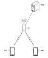
- FIG. 1 is an explanatory diagram illustrating an example of a schematic configuration of a communication system 1 according to the present embodiment.
- the communication system 1 includes a connection node 10, a management device 100, and two or more wireless communication terminals 200.
- connection node 10 performs wireless communication with the wireless communication terminal 200 located in the communication area of the connection node 10. Further, the connection node 10 communicates with the management apparatus 100 via the network. For example, the connection node 10 transfers information transmitted from the management apparatus 100 to the wireless communication terminal 200 and transfers information transmitted from the wireless communication terminal 200 to the management apparatus 100. As an example, the connection node 10 is a base station of a cellular network.
- the management device 100 manages the direct connection between the wireless communication terminals 200.
- the management device 100 manages direct connection between the two wireless communication terminals 200.
- the wireless communication terminal 200 When the wireless communication terminal 200 is located within the communication area of the connection node 10, the wireless communication terminal 200 is connected to the connection node 10 and performs wireless communication with the connection node 10. The wireless communication terminal 200 is directly connected to another wireless communication terminal 200 and performs wireless communication with the other wireless communication terminal 200.
- the communication system 1 may naturally include three or more wireless communication terminals 200.
- the management apparatus 100 issues identification information for direct connection between the two wireless communication terminals 200 and notifies the two wireless communication terminals 200 of the identification information. Further, the two wireless communication terminals 200 perform control for direct connection between the two wireless communication terminals 200 using the identification information. Thereby, for example, it is possible to prevent an unintended connection between the wireless communication terminals 200 without distributing the identification information of the wireless communication terminal 200.
- FIG. 2 is a block diagram illustrating an example of the configuration of the management apparatus 100 according to the present embodiment.
- the management apparatus 100 includes a communication unit 110, a storage unit 120, and a processing unit 130.
- the communication unit 110 communicates with other nodes.
- the communication unit 110 communicates with the wireless communication terminal 200 via the connection node 10.
- Storage unit 120 The storage unit 120 temporarily or permanently stores a program and data for the operation of the management apparatus 100.
- the storage unit 120 stores a table for managing direct connections between the wireless communication terminals 200 (hereinafter referred to as “management table”). Specific contents of the management table will be described later.
- the processing unit 130 provides various functions of the management apparatus 100.
- the processing unit 130 includes a management unit 131 and a notification unit 133.
- connection ID identification information for direct connection between the two wireless communication terminals 200
- the management unit 131 determines to attempt a direct connection between the two wireless communication terminals 200. Then, the management unit 131 issues a connection ID for the direct connection. More specifically, for example, the management unit 131 newly generates a connection ID or selects one connection ID from one or more existing connection IDs that are not used, thereby obtaining a connection ID. Issue. For example, the management unit 131 issues a connection ID for each pair of wireless communication terminals that perform direct connection.
- the direct connection is a direct connection according to a wireless LAN (Local Area Network) standard.
- the wireless LAN standard is IEEE802.11 (for example, IEEE802.11a, 11b, 11g, 11n, 11ac, and 11ad) or Wi-Fi Direct.
- the management unit 131 generates communication parameters for direct connection between the two wireless communication terminals 200.
- the communication parameters include the role at the time of direct connection, the frequency channel to be used, the service set identifier (Service Set Identifier: SSID), the pre-shared key (Pairwise Master Key: PMK) and / or the search. Includes scheduled start time.
- SSID Service Set Identifier
- PMK Pre-shared key
- the above-described role is, for example, a first role that is a role of a parent device that waits for a connection request, or a second role that is a role of a child device that requests connection.
- the direct connection is a direct connection of Wi-Fi Direct
- the first role is a group owner
- the second role is a client.
- the management unit 131 determines the role of each of the two wireless communication terminals 200.
- the role of one of the two wireless communication terminals 200 becomes the first role (for example, the group owner), and the role of the other wireless communication terminal of the two wireless communication terminals 200 increases.
- the role becomes the second role (eg, client).
- the management unit 131 updates a table for managing direct connections between wireless communication terminals (ie, a management table).
- the management table includes a connection ID as an information item.
- the management table includes, for example, a terminal ID (for example, an IP address or an ID in a cellular network) of the wireless communication terminal 200.
- the management unit 131 registers the connection ID and the terminal ID in the management table.
- the management table includes some or all of the communication parameters. More specifically, for example, the management table includes a role in direct connection and / or a frequency channel to be used. For example, the management unit 131 registers the communication parameter in the management table when generating the communication parameter.
- the management table includes information indicating a direct connection state between the wireless communication terminals 200. For example, when the state of the direct connection changes, the management unit 131 updates the information indicating the state.
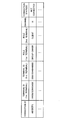
- FIG. 3 is an explanatory diagram for explaining an example of the management table.
- a management table is shown.
- the management table includes “connection ID”, “terminal ID”, “role”, “channel”, and “connection state” as information items. Such information is registered in the management table for each pair of wireless communication terminals that are directly connected.
- the management unit 131 deletes information related to the direct connection (connection ID, terminal ID, and the like) from the management table. That is, the management unit 131 deletes the registration of the connection ID when the direct connection ends. Thereby, for example, connection ID registration and direct connection can be synchronized. For example, the wireless communication terminal 200 notifies the management device 100 of the end of the direct connection.
- the management unit 131 may further manage the amount of data transmitted / received between the wireless communication terminals 200.
- the amount of data may be associated with a connection ID for direct connection between the wireless communication terminals 200 and stored (for example, in the storage unit 250).
- the wireless communication terminal 200 may notify the management apparatus 100 of the amount of data.
- connection ID (that is, identification information for direct connection between the two wireless communication terminals 200).
- the notification unit 133 when the connection ID is generated, notifies the two wireless communication terminals 200 of the connection ID. More specifically, for example, the notification unit 133 notifies the two wireless communication terminals 200 of a connect request (Connect Request) including the connection ID via the communication unit 110.
- Connect Request a connect request
- the notification unit 133 notifies the two wireless communication terminals 200 of the communication parameters for direct connection between the two wireless communication terminals 200.
- the notification unit 133 when the communication parameter is generated, notifies the two wireless communication terminals 200 of the communication parameter. More specifically, for example, the notification unit 133 notifies the two wireless communication terminals 200 of a connection request including the communication parameter (and the connection ID) via the communication unit 110.
- Such notification of communication parameters reduces the time required for the direct connection, for example.
- the burden on the wireless communication terminal 200 at the time of the direct connection can be reduced.
- the notification unit 133 requests at least one of the two wireless communication terminals 200 directly connected to each other to disconnect the direct connection between the two wireless communication terminals 200.
- the notification unit 133 notifies the two wireless communication terminals 200 of a disconnect request (Disconnect Request) including the connection ID for the direct connection via the communication unit 110.
- FIG. 4 is a block diagram illustrating an example of a configuration of the wireless communication terminal 200 according to the present embodiment.
- the wireless communication terminal 200 includes a first antenna unit 210, a first wireless communication unit 220, a second antenna unit 230, a second wireless communication unit 240, a storage unit 250, and a processing unit 260.
- the first antenna unit 210 radiates the signal output from the first wireless communication unit 220 into space as a radio wave. In addition, the first antenna unit 210 converts a radio wave in the space into a signal and outputs the signal to the first wireless communication unit 220.
- the first wireless communication unit 220 performs wireless communication. For example, the first wireless communication unit 220 performs wireless communication with the connection node 10. That is, the first wireless communication unit 220 receives a signal transmitted from the connection node 10 and transmits a signal to the connection node 10.
- connection node 10 is a base station of a cellular network.
- the first wireless communication unit 220 is a communication unit for wireless communication in accordance with a cellular communication standard.
- the first wireless communication unit 220 may perform wireless communication with another wireless communication terminal 200. That is, the first wireless communication unit 220 may receive a signal transmitted from another wireless communication terminal 200 and transmit a signal to the other wireless communication terminal 200.
- the second antenna unit 230 radiates the signal output from the second wireless communication unit 240 into space as a radio wave. In addition, the second antenna unit 230 converts a radio wave in the space into a signal and outputs the signal to the second wireless communication unit 240.
- the second wireless communication unit 240 performs wireless communication.
- the second wireless communication unit 240 performs short-range wireless communication as compared to the wireless communication of the first wireless communication unit 220.
- the second wireless communication unit 240 performs wireless communication with other wireless communication terminals 200. That is, the second wireless communication unit 240 receives a signal transmitted from another wireless communication terminal 200 and transmits a signal to the other wireless communication terminal 200.
- the second wireless communication unit 240 is a communication unit for wireless communication according to the wireless LAN standard.
- the second wireless communication unit 240 may perform wireless communication with a wireless LAN access point.
- the storage unit 250 temporarily or permanently stores a program and data for the operation of the wireless communication terminal 200.
- the storage unit 250 stores a table (hereinafter referred to as “connection table”) in which information related to direct connection with another wireless communication terminal 200 is registered. Specific contents of the connection table will be described later.
- the processing unit 260 provides various functions of the wireless communication terminal 200.
- the processing unit 260 includes an information acquisition unit 261 and a connection control unit 263.
- the information acquisition unit 261 acquires identification information (ie, connection ID) for direct connection between the two wireless communication terminals 200.
- connection ID identification information
- the wireless communication terminal 200 including the information acquisition unit 261 is one of the two wireless communication terminals 200.
- the connection ID is issued by another device different from the two wireless communication terminals 200.
- the other device is the management device 100.
- the management apparatus 100 issues the connection ID
- the management apparatus 100 notifies the two wireless communication terminals 200 of the connection ID, and each of the two wireless communication terminals 200 receives the connection ID.
- the connection ID is stored in the storage unit 250.
- the information acquisition unit 261 acquires the connection ID from the storage unit 250.
- the storage unit 250 stores a table in which information related to direct connection is registered (that is, a connection table), and the connection ID is registered in the connection table.
- the registration in the connection table is performed by the processing unit 260, for example.
- connection table The information registered in the connection table differs depending on, for example, the role of the wireless communication terminal 200 at the time of direct connection. More specifically, for example, the role of one of the two wireless communication terminals 200 is the first role, and the other wireless communication terminal 200 of the two wireless communication terminals 200 is the first role. The roll becomes the second roll. The information registered in the connection table differs depending on whether the role of the wireless communication terminal 200 that stores the connection table is the first role or the second role.
- the first role is a role of a parent device that waits for a connection request, and is a group owner as an example.
- a specific example of information registered in the connection table when the role of the wireless communication terminal 200 is the first role will be described with reference to FIG.
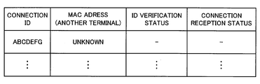
- FIG. 5 is an explanatory diagram for describing a first example of information registered in the connection table when the role of the wireless communication terminal 200 is the first role.
- a connection table including “connection ID”, “MAC address”, “ID verification status (ID verification status)”, and “connection reception status” as information items is shown.
- Connection ID is a connection ID notified by the management apparatus 100.
- MAC address is the MAC address of another wireless communication terminal 200 to which the wireless communication terminal 200 is directly connected using the connection ID.
- ID verification state indicates whether verification using a connection ID is valid or invalid.
- the “connection acceptance state” indicates whether direct connection by another wireless communication terminal 200 is permitted or rejected.
- connection ID is registered as an information item “connection ID” in the connection table.
- no MAC address is registered as the information item “MAC address”.
- valid is registered as the information item “ID verification state”.
- reject is registered as the information item “connection acceptance state”.
- the second role is a role of a slave that requests connection, and is a client as an example.
- the connection table when the role of the wireless communication terminal 200 is the second role will be described with reference to FIG.
- FIG. 6 is an explanatory diagram for explaining a first example of information registered in the connection table when the role of the wireless communication terminal 200 is the second role.
- a connection table including information items similar to the example of FIG. 5 is shown.
- the management apparatus 100 issues a connection ID and notifies the wireless communication terminal 200 of the connection ID
- the connection ID is registered as an information item “connection ID” in the connection table.
- no MAC address is registered as the information item “MAC address”.
- the role of the wireless communication terminal 200 is the second role, neither information is registered as the information items “ID verification state” and “connection acceptance information” in the connection table. Any temporary value may be registered as the information items “ID verification state” and “connection acceptance information”.
- the information acquisition unit 261 acquires communication parameters for direct connection between the two or more wireless communication terminals.
- the management apparatus 100 when the management apparatus 100 generates the communication parameter, the communication parameter is notified to the two wireless communication terminals 200, and each of the two wireless communication terminals 200 transmits the communication parameter. Receive. Then, the communication parameter is stored in the storage unit 250. Then, the information acquisition unit 261 acquires the communication parameter from the storage unit 250.
- the communication parameters include a role for direct connection. Therefore, the radio communication terminal 200 performs the operation of the role (for example, the first roll or the second roll) based on the role of the radio communication terminal 200 included in the communication parameter. Further, as described above, the wireless communication terminal 200 registers information corresponding to the role (for example, the first role or the second role) in the connection table.
- the role for example, the first roll or the second roll
- connection control unit 263 performs control for direct connection between the two wireless communication terminals 200 (hereinafter referred to as “connection control”) using the connection ID.
- connection control control for direct connection between the two wireless communication terminals 200
- the wireless communication terminal 200 including the connection control unit 263 is one of the two wireless communication terminals 200.
- the direct connection is, for example, a connection for wireless communication performed by the wireless communication terminal 200 using the second wireless communication unit 240 (for example, wireless communication according to the wireless LAN standard).
- the direct connection may be a connection for wireless communication performed by the wireless communication terminal 200 using the first wireless communication unit 220 (for example, wireless communication according to the cellular communication standard).
- connection control differs depending on the role of the wireless communication terminal 200 (including the connection control unit 263).
- connection control is performed, for example, as follows: Control.
- the connection control includes authentication of another wireless communication terminal 200 attempting a direct connection with the wireless communication terminal 200. That is, the connection control unit 263 authenticates another wireless communication terminal 200 that attempts to connect directly to the wireless communication terminal 200 using the connection ID. As described above, the wireless communication terminal 200 is one of the two wireless communication terminals 200, and the authentication is performed by the other wireless communication terminal 200 of the two wireless communication terminals 200. It is to verify whether it is the other wireless communication terminal 200.
- the authentication includes verifying whether the information provided by the other wireless communication terminal 200 is information corresponding to the connection ID.
- the information corresponding to the connection ID is information that matches the connection ID.
- the management apparatus 100 notifies the two wireless communication terminals 200 of the same connection ID, and the wireless communication terminal 200 (that is, one of the two wireless communication terminals 200) 200) acquires the connection ID and stores it in the storage unit 250. Also, another wireless communication terminal 200 attempting to connect directly to the wireless communication terminal 200 provides information to the wireless communication terminal 200. As an example, the wireless communication terminal 200 starts transmitting a beacon before the scheduled search start time, which is one of the communication parameters described above, and the other wireless communication terminal 200 transmits a beacon after the scheduled search start time. In response to the reception, a probe request including the information and the SSID is transmitted. The beacon does not include an SSID, for example.
- the information acquisition unit 261 acquires the SSID that is one of the communication parameters described above, and the connection control unit 263 verifies whether the SSID and the SSID included in the probe request match.
- the information acquisition unit 261 acquires the connection ID from the storage unit 250 (connection table), and the connection control unit 263 determines whether the information provided by the other wireless communication terminal 200 matches the connection ID.
- the SSID which is one of the communication parameters described above, matches the SSID included in the probe request, and the information matches the connection ID.
- the other wireless communication terminal 200 is a wireless communication terminal 200 provided with the connection ID by the management apparatus 100 (that is, the other wireless communication terminal 200 of the two wireless communication terminals 200). I understand that.
- the authentication can be successful.
- the authentication fails.
- two or more connection IDs are registered in the connection management table, does the information provided by the other wireless communication terminal 200 match any of the two or more connection IDs? Is verified. If the information matches any connection ID, the authentication can succeed. On the other hand, if the information does not match any connection ID, the authentication fails.
- the wireless communication terminal 200 can permit direct connection between the intended wireless communication terminals 200 and prevent unintended direct connection between the wireless communication terminals 200.
- the connection control unit 263 authenticates another wireless communication terminal 200 attempting a direct connection with the wireless communication terminal 200 using the connection ID.
- the authentication is successful only when the connection ID use condition is satisfied.
- the availability condition is that authentication using the connection ID has not yet been successful. That is, the authentication can be successful if the authentication using the connection ID has not yet been successful, but fails if the authentication using the connection ID has already been successful.
- the connection control unit 263 verifies whether the information provided by the other wireless communication terminal 200 matches the connection ID. It can be seen that it matches the ID. In this case, the connection control unit 263 checks an “ID verification status” corresponding to the connection ID in the connection table. As a result, if the “ID verification state” is “valid”, the authentication of the other wireless communication terminal 200 is successful. Then, when the authentication is successful, the connection control unit 263 updates the connection table.
- the connection control unit 263 updates the connection table.
- FIG. 7 is an explanatory diagram for explaining a second example of information registered in the connection table when the role of the wireless communication terminal 200 is the first role.
- a connection table including information items similar to the example of FIG. 5 is shown.
- the connection control unit 263 registers the MAC address of the other wireless communication terminal 200 as the information item “MAC address” of the connection table.
- the connection control unit 263 changes “valid” registered as the information item “ID verification state” of the connection table to “invalid”. That is, when information matching the connection ID is provided, “invalid” is registered as the “ID verification state”.
- the connection control unit 263 changes “reject” registered as the information item “connection acceptance state” of the connection table to “permit (admit)”. That is, when the authentication is successful, “admit” is registered as the “connection acceptance state”.
- connection control unit 263 checks the “ID verification state” corresponding to the connection ID in the connection table, and as a result, for example, the “ID verification state” is found to be “invalid”. In this case, authentication of the other wireless communication terminal 200 fails. That is, if the authentication using the connection ID has already been successful, the authentication fails even if information that matches the connection ID is further provided.
- connection ID is intercepted when providing the connection ID to the wireless communication terminal 200 by another wireless communication terminal 200
- the subsequent communication to the wireless communication terminal 200 using the connection ID is performed.
- Direct connection is not allowed. Therefore, for example, unauthorized direct connection to the wireless communication terminal 200 can be prevented.
- connection control includes permitting or denying direct connection to the wireless communication terminal 200 by the other wireless communication terminal 200.
- connection control unit 263 rejects the direct connection by the other wireless communication terminal 200 when the authentication of the other wireless communication terminal 200 attempting the direct connection with the wireless communication terminal 200 fails.
- the MAC address of the other wireless communication terminal 200 is registered as the information item “MAC address” of the connection table, for example, as shown in FIG. It has not been. Therefore, even when the connection is requested by the other wireless communication terminal 200, the connection control unit 263, if the MAC address of the other wireless communication terminal 200 is not registered in the connection table, the other The direct connection by the wireless communication terminal 200 is rejected.
- connection control unit 263 can permit the direct connection by the other wireless communication terminal 200 when the authentication is successful, for example. For example, if the authentication is successful, the connection control unit 263 permits the direct connection by the other wireless communication terminal 200 within the restriction period, and outside the restriction period, the connection by the other wireless communication terminal 200. Reject direct connection. Note that “rejecting a direct connection” here does not mean stopping an already established direct connection, but means rejecting a newly requested direct connection.
- the restriction period is a period until data communication between the wireless communication terminal 200 and the other wireless communication terminal 200 becomes possible. That is, the connection control unit 263 permits the direct connection within a period until the data communication is possible, and rejects the direct connection after the data communication is possible.
- the connection control unit 263 checks whether or not the MAC address of the other wireless communication terminal 200 that has transmitted the association request is registered in the connection table.
- the connection control unit 263 checks the “connection acceptance state” corresponding to the MAC address in the connection table. For example, as illustrated in FIG. 7, when “admit” is registered as the “connection acceptance state”, the connection control unit 263 transmits the connection to the wireless communication terminal 200 by the other wireless communication terminal 200. Allow direct connection.
- the wireless communication terminal 200 transmits an association response indicating success to the other wireless communication terminal 200.
- a 4-way handshake is performed between the wireless communication terminal 200 and the other wireless communication terminal 200 by using a pre-shared key (PMK) that is one of the communication parameters described above.
- PMK pre-shared key
- a data path in the network layer is opened between the wireless communication terminal 200 and the other wireless communication terminal 200, and data communication between the wireless communication terminal 200 and the other wireless communication terminal 200 becomes possible.
- the connection control unit 263 changes the “connection acceptance state” in the connection table from “admit” to “reject”.
- connection control unit 263 Rejects direct connection to the wireless communication terminal 200 by the other wireless communication terminal 200.
- “permission” is registered as the “connection acceptance state” until the data communication between the wireless communication terminal 200 and the other wireless communication terminal 200 becomes possible. And the other wireless communication terminal 200 are permitted to be directly connected.
- “reject” is registered as the “connection acceptance state”, and thus the direct connection is rejected.
- direct connection is allowed only within the limited period. Thereby, for example, since direct connection to the wireless communication terminal 200 by another wireless communication terminal 200 is restricted, unauthorized direct connection to the wireless communication terminal 200 can be prevented.
- the limited period is, for example, a period until the data communication becomes possible.
- the wireless communication terminal 200 while ensuring data communication between the wireless communication terminal 200 and another wireless communication terminal 200, it is possible to extremely shorten a period during which an unauthorized direct connection can be performed thereafter.
- the connection control is performed as follows, for example: Includes specific controls.
- connection control includes providing the connection ID to the other wireless communication terminal 200 of the two wireless communication terminals 200.
- the management apparatus 100 notifies the two wireless communication terminals 200 of the same connection ID, and the wireless communication terminal 200 (that is, one of the two wireless communication terminals 200) 200) acquires the connection ID and stores it in the storage unit 250. Thereafter, the information acquisition unit 261 acquires the connection ID from the storage unit 250, and the connection control unit 263 provides the connection ID to the other wireless communication terminal 200 of the two wireless communication terminals 200.
- the wireless communication terminal 200 receives the beacon (not including the SSID) after the scheduled search start time that is one of the communication parameters, and the SSID that is one of the communication parameters described above and the connection ID. Send a probe request containing After that, the other wireless communication terminal 200 of the two wireless communication terminals 200 authenticates the wireless communication terminal 200 using the connection ID.
- the other wireless communication terminal 200 of the two wireless communication terminals 200 permits direct connection between the intended wireless communication terminals 200 and prevents unintended direct connection between the wireless communication terminals 200. It becomes possible.
- connection control unit 263 updates the connection table. More specifically, for example, as shown in FIG. 9, the connection control unit 263 converts the MAC address of the other wireless communication terminal 200 out of the two wireless communication terminals 200 into the information item “MAC” of the connection table. Register as “Address”.
- connection control unit 263 disconnects the direct connection between the two wireless communication terminals 200 (that is, the wireless communication terminal 200 and the other wireless communication terminal 200).
- connection control unit 263 disconnects the direct connection by performing a disconnection procedure for the direct connection.
- the disconnection procedure includes, for example, transmission of a deauthentication frame.
- connection control unit 263 disconnects the direct connection in response to a disconnection request from the management apparatus 100.
- the management apparatus 100 requests the wireless communication terminal 200 to disconnect the direct connection between the two wireless communication terminals 200 (that is, the wireless communication terminal 200 and the other wireless communication terminal 200). More specifically, for example, the management apparatus 100 notifies the wireless communication terminal 200 of a disconnect request (Disconnect Request) including the connection ID for the direct connection. Then, the connection control unit 263 specifies the direct connection from the connection ID and the connection table, and performs a disconnection procedure for the direct connection. As a result, the direct connection is disconnected.
- a disconnect request Disconnect Request
- the management apparatus 100 can disconnect the direct connection between the two wireless communication terminals 200 as necessary. Therefore, for example, the management apparatus 100 can control the direct connection more freely or more finely.
- connection control unit 263 disconnects the direct connection when the connection with the management apparatus 100 is disconnected.
- connection control unit 263 causes the two wireless communication terminals 200 (that is, the wireless communication terminal 200 and the other wireless communication terminal 200). ) Disconnection procedure for direct connection. As a result, the direct connection is disconnected.
- the direct connection of the wireless communication terminal 200 to which the management apparatus 100 cannot communicate can be disconnected. Therefore, for example, it is possible to prevent direct connection of the wireless communication terminal 200 that is not controlled by the management apparatus 100.
- connection control unit 263 disconnects the direct connection when the communication between the two wireless communication terminals 200 is not performed for a predetermined time or more.
- connection control unit 263 A disconnection procedure for direct connection between the two wireless communication terminals 200 is performed. As a result, the direct connection is disconnected.
- the direct connection can be quickly disconnected.
- connection control unit 263 disconnects the direct connection between the two wireless communication terminals 200.
- the connection control unit 263 deletes, for example, information related to the direct connection (connection ID, MAC address, and the like) from the connection table. Thereby, for example, even if an unauthorized direct connection is attempted using the connection ID after the direct connection is terminated, the unauthorized direct connection is not permitted.
- connection control unit 263 instructs the management apparatus 100 to establish direct connection between the two wireless communication terminals 200 (that is, the wireless communication terminal 200 and the other wireless communication terminal 200). Notice. For example, when the direct connection is established, the connection control unit 263 notifies the management apparatus 100 of a connect response including a connection ID for the direct connection.
- connection control unit 263 notifies the management apparatus 100 of disconnection of the direct connection between the two wireless communication terminals 200 (that is, the wireless communication terminal 200 and the other wireless communication terminal 200). For example, the connection control unit 263 notifies the management device 100 of a disconnect response (Disconnect Response) or a disconnect indication (Disconnect Indication) including the connection ID for the direct connection.
- a disconnect response Disconnect Response
- a disconnect indication Disconnect Indication
- the management device 100 can manage the state of the direct connection between the two wireless communication terminals 200.
- connection control unit 263 may notify the management apparatus 100 of a failure to establish a direct connection between the two wireless communication terminals 200 (that is, the wireless communication terminal 200 and the other wireless communication terminal 200). For example, if the connection control unit 263 fails to establish the direct connection, the connection control unit 263 notifies the management apparatus 100 of the connect response including the connection ID for the direct connection and indicating the failure of the direct connection. May be.
- connection control unit 263 may notify the management apparatus 100 of the amount of data transmitted / received between the two wireless communication terminals 200.
- the connection control unit 263 may notify the management apparatus 100 of the connection ID for the direct connection between the two wireless communication terminals 200 and the amount of the data.
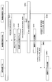
- connection processing ⁇ 3.1. Flow of connection processing> First, an example of connection processing according to the present embodiment will be described with reference to FIGS. 10A and 10B.
- 10A and 10B are sequence diagrams illustrating an example of a schematic flow of connection processing according to the present embodiment.
- the management apparatus 100 determines to attempt a direct connection between the two wireless communication terminals 200 (that is, the wireless communication terminal 200A and the wireless communication terminal 200B), and issues a connection ID for the direct connection (S401). .
- the connection ID is registered in a management table as shown in FIG. 3, for example.
- the management unit 131 generates communication parameters for the direct connection (S403).
- the communication parameter includes, for example, a role for direct connection, and the role of each of the two wireless communication terminals 200 is determined.
- the role of the wireless communication terminal 200A is a group owner
- the role of the wireless communication terminal 200B is a client.
- the communication parameters are registered in a management table as shown in FIG. 3, for example.
- the management apparatus 100 transmits a connect request (Connect Request) including the connection ID and the communication parameter to the two wireless communication terminals 200 (S405, S407).
- the wireless communication terminal 200A updates the connection table of the wireless communication terminal 200A, for example, as shown in FIG. 5 (S409). Then, the wireless communication terminal 200A starts an operation as a group owner (S411). Note that the wireless communication terminal 200A starts transmitting a beacon by the scheduled search start time which is one of communication parameters. Note that the beacon does not include an SSID, for example.
- the wireless communication terminal 200B updates the connection table of the wireless communication terminal 200B, for example, as shown in FIG. 6 (S413). Then, the wireless communication terminal 200B starts an operation as a client (S415).
- the wireless communication terminal 200B transmits a probe request including an SSID and a connection ID, which are one of the communication parameters, in response to reception of a beacon after the scheduled search start time (S417).
- the wireless communication terminal 200A verifies whether the connection ID provided by the wireless communication terminal 200B matches the connection ID in the connection table of the wireless communication terminal 200A (S419). As a result, it can be seen that the provided connection ID matches the connection ID in the connection table. Also, the radio communication terminal 200A checks the “ID verification state” corresponding to the connection ID in the connection table (S421). As a result, it is understood that the “ID verification state” is “valid”. In such a case, the authentication of the wireless communication terminal 200B is successful. Then, the radio communication terminal 200A updates the connection table of the radio communication terminal 200A, for example, as shown in FIG. 7 (S423). Note that authentication fails when the provided connection ID does not match the connection ID in the connection table, and when the “ID verification state” corresponding to the connection ID is “invalid”.
- the wireless communication terminal 200A transmits a probe response including the connection ID (S425). Then, the wireless communication terminal 200B updates the connection table of the wireless communication terminal 200B, for example, as shown in FIG. 9 (S427).
- the radio communication terminal 200B transmits an association request (Association Request) to the radio communication terminal 200A (S431).
- the wireless communication terminal 200A checks whether or not the MAC address of the wireless communication terminal 200B that transmitted the association request is registered in the connection table of the wireless communication terminal 200A (S433). As a result, it can be seen that the MAC address is registered in the connection table. Also, the wireless communication terminal 200A checks the “connection acceptance state” corresponding to the MAC address in the connection table (S435). As a result, it is understood that “admit” is registered as the “connection acceptance state”. In such a case, the wireless communication terminal 200A permits a direct connection to the wireless communication terminal 200A by the wireless communication terminal 200B. When the MAC address is not registered in the connection table of the wireless communication terminal 200A, and when the “connection acceptance state” corresponding to the MAC address is “reject”, the wireless communication terminal 200A The direct connection to the wireless communication terminal 200A is rejected.
- the radio communication terminal 200A transmits an association response indicating success (S437). Also, the wireless communication terminal 200A and the wireless communication terminal 200B perform a 4-way handshake using a pre-shared key (PMK) that is one of the communication parameters (S439). As a result, a data path between the radio communication terminal 200A and the radio communication terminal 200B is opened, and data communication between the radio communication terminal 200A and the radio communication terminal 200B becomes possible. Further, the wireless communication terminal 200A updates the connection table of the wireless communication terminal 200A, for example, as shown in FIG. 8 (S441).
- PMK pre-shared key
- the radio communication terminal 200A and the radio communication terminal 200B transmit a connect response (Connect Response) indicating the success of establishment of direct connection to the management apparatus 100 (S443, S445).
- the connect response includes the connection ID.
- the management apparatus 100 updates the management table (S447). Specifically, the management apparatus 100 updates the “connection state” of the management table from “Not Connected” to “Connected”.
- the wireless communication terminal 200A and the wireless communication terminal 200B manage the connect response indicating the failure of the direct connection establishment. You may transmit to 100.
- the connect response may include the connection ID.
- the management apparatus 100 may delete the information (connection ID, MAC address, etc.) regarding the said direct connection from the said connection table.
- FIG. 11 is a sequence diagram illustrating an example of a schematic flow of the first end process according to the present embodiment.
- the first end process is an end process in response to a disconnection request from the management apparatus 100.
- the management apparatus 100 determines the end of the direct connection between the two wireless communication terminals 200 (that is, the wireless communication terminal 200A and the wireless communication terminal 200B) (S501). Then, the management apparatus 100 updates the management table (S503). More specifically, the management apparatus 100 updates the “connection state” of the management table from “Connected” to “Trying Disconnection”. Then, the management device 100 transmits a disconnect request (Disconnect Request) including the connection ID for the direct connection to the two wireless communication terminals 200 (S505, S507).
- Disconnect Request a disconnect request including the connection ID for the direct connection to the two wireless communication terminals 200 (S505, S507).
- the two wireless communication terminals 200 perform a disconnection procedure for the direct connection (S509).
- the disconnection procedure includes, for example, transmission of a deauthentication frame from one of the two wireless communication terminals 200 to the other.
- the direct connection is disconnected and terminated.
- the radio communication terminal 200A ends the operation as a group owner (S511).
- the two wireless communication terminals 200 transmit a disconnect response including the connection ID to the management apparatus 100 (S513, S515). Then, the management apparatus 100 deletes information related to the direct connection (connection ID, terminal ID, etc.) from the management table (S517). Also, the two wireless communication terminals 200 also delete the information related to the direct connection (connection ID, MAC address, etc.) from the connection table (S519, S521).
- disconnect request may be transmitted to only one of the radio communication terminal 200A and the radio communication terminal 200B.
- FIG. 12 is a sequence diagram illustrating an example of a schematic flow of the second end process according to the present embodiment.
- the second termination process is a termination process in response to the disconnection of the connection between the management apparatus 100 and the wireless communication terminal 200.
- steps S533 to S545 in the second end process shown in FIG. 12 are the same as steps SS509 to S521 in the first end process described with reference to FIG. Therefore, only step S531 will be described here.
- the wireless communication terminal 200A detects disconnection between the wireless communication terminal 200A and the management apparatus 100 (S531). Thereafter, a disconnection procedure (S533) is performed.
- the wireless communication terminal 200B may detect disconnection of the connection between the wireless communication terminal 200B and the management apparatus 100.
- FIG. 13 is a sequence diagram illustrating an example of a schematic flow of a third end process according to the present embodiment.
- the third termination process is a termination process in response to the fact that wireless communication is not performed for a predetermined time or longer.
- steps S563 to S575 in the third end process shown in FIG. 13 are the same as steps SS509 to S521 in the first end process described with reference to FIG. Therefore, only step S561 will be described here.
- the wireless communication terminal 200A detects that communication between the wireless communication terminal 200A and the wireless communication terminal 200B has not been performed for a predetermined time (S561). Thereafter, a disconnection procedure (S563) is performed.
- the wireless communication terminal 200B detects that communication between the wireless communication terminal 200A and the wireless communication terminal 200B has not been performed for a predetermined time or more. May be.
- the wireless communication terminal 200 permits the direct connection by the other wireless communication terminal 200 within the limited period.
- the direct connection by the other wireless communication terminal 200 is rejected outside the restriction period.
- the restriction period is a period until data communication between the wireless communication terminal 200 and the other wireless communication terminal 200 becomes possible, for example.
- the restriction period is not limited to the period until the data communication is possible, and includes a further period.
- connection control unit 263 Control for direct connection-Case of first role---Permit or deny connection
- the connection control unit 263 performs the above processing within a limited period when the authentication is successful.
- the direct connection by the other wireless communication terminal 200 is permitted, and the direct connection by the other wireless communication terminal 200 is rejected outside the restriction period.
- the limited period is a period until it is determined that the direct connection between the wireless communication terminal 200 and the other wireless communication terminal 200 is stable. including. That is, the connection control unit 263 permits the direct connection within a period until it is determined that the direct connection is stable, and after determining that the direct connection is stable, the connection control unit 263 performs the direct connection. I refuse.
- connection control unit 263 does not update the connection table of the wireless communication terminal 200 after the network layer data path is opened between the wireless communication terminal 200 and the other wireless communication terminal 200. That is, the “connection acceptance state” in the connection table is not changed from “admit” to “reject”. Thereafter, the “connection acceptance state” is maintained as “admit” until it is determined that the direct connection between the wireless communication terminal 200 and the other wireless communication terminal 200 is stable. When it is determined that the direct connection is stable, the connection control unit 263 changes the “connection acceptance state” in the connection table from “admit” to “reject”.
- Whether the direct connection is stable is determined by the processing unit 260, for example. Specifically, for example, the processing unit 260 monitors the state of the direct connection and determines whether the direct connection is stable based on the state.
- the situation of the direct connection includes, for example, the frequency of disconnection and / or reconnection.
- the processing unit 260 may monitor the communication quality of the direct connection and determine whether the direct connection is stable based on the communication quality (and the situation of the direct connection).
- the communication quality of the direct connection may include, for example, received signal strength, a modulation and coding scheme to be used, and / or a retransmission occurrence probability.
- the connection control unit 263 permits the direct connection in a period after it is determined that the direct connection is unstable.
- the connection control unit 263 displays the “connection acceptance state” in the connection table of the wireless communication terminal 200. Is changed from “reject” to “admit”. For example, when it is determined that the direct connection is stable thereafter, the connection control unit 263 changes the “connection acceptance state” in the connection table of the wireless communication terminal 200 from “permitted” to “rejected”. The determination as to whether the direct connection is unstable is performed by the processing unit 260, for example.
- the schematic flow of the connection process according to the modification of the present embodiment is an example of the schematic flow of the connection process according to the present embodiment described with reference to FIGS. 10A and 10B except for the following points, for example. Is the same.
- step S441 shown in FIG. 10B is not included. That is, in the connection process according to the modification of the present embodiment, after the data communication between the wireless communication terminal 200A and the wireless communication terminal 200B becomes possible, the connection table of the wireless communication terminal 200A is not updated. More specifically, the radio communication terminal 200A does not change the “connection acceptance status” in the connection table of the radio communication terminal 200A from “admit” to “reject”, but changes the “connection acceptance status”. Keep “admit”.
- FIG. 14 is a flowchart illustrating an example of a schematic flow of processing in the wireless communication terminal according to the modification of the present embodiment. Note that this processing is performed after the connection processing according to the modification of the present embodiment, the wireless communication terminal 200 operating as the first role (group owner) (for example, the wireless communication terminal 200A shown in FIGS. 10A and 10B). Is done.
- group owner for example, the wireless communication terminal 200A shown in FIGS. 10A and 10B.
- the processing unit 260 monitors the state (and / or communication quality) of direct connection between the wireless communication terminal 200 and another wireless communication terminal 200 (S461), and determines whether the direct connection is stable (S461). S463). When it is determined that the direct connection is stable (S463: YES), the connection control unit 263 updates the connection table (S465). That is, the connection control unit 263 changes the “connection acceptance status” in the connection table from “admit” to “reject”. On the other hand, when it is determined that the direct connection is not stable (S463: NO), the process returns to step S461.
- the processing unit 260 monitors the state (and / or communication quality) of direct connection between the wireless communication terminal 200 and another wireless communication terminal 200 (S471), and determines whether the direct connection is unstable. (S473).
- the connection control unit 263 updates the connection table (S475). That is, the connection control unit 263 changes the “connection acceptance state” in the connection table from “rejected” to “permitted”. Then, the process returns to step S461.
- the process returns to step S471.
- the management apparatus 100 may be realized as any type of server such as a tower server, a rack server, or a blade server. Further, at least a part of the components of the management apparatus 100 is realized as a module mounted on a server (for example, an integrated circuit module configured by one die, or a card or a blade inserted into a blade server slot). May be.
- the wireless communication terminal 200 is a smartphone, a tablet PC (Personal Computer), a notebook PC, a portable game terminal, a mobile terminal such as a portable / dongle type mobile router or a digital camera, or an in-vehicle such as a car navigation device. It may be realized as a terminal. Further, the wireless communication terminal 200 may be realized as a terminal (also referred to as an MTC (Machine Type Communication) terminal) that performs M2M (Machine To Machine) communication. Furthermore, at least some of the components of the wireless communication terminal 200 may be realized as a module (for example, an integrated circuit module configured by one die) mounted on these terminals.
- MTC Machine Type Communication
- FIG. 15 is a block diagram illustrating an example of a schematic configuration of a server 600 to which the technology according to the present disclosure can be applied.
- the server 600 includes a processor 601, a memory 602, a storage 603, a network interface 604, and a bus 606.
- the processor 601 may be a CPU (Central Processing Unit) or a DSP (Digital Signal Processor), for example, and controls various functions of the server 600.
- the memory 602 includes a RAM (Random Access Memory) and a ROM (Read Only Memory), and stores programs and data executed by the processor 601.
- the storage 603 can include a storage medium such as a semiconductor memory or a hard disk.
- the network interface 604 is a wired communication interface for connecting the server 600 to the wired communication network 605.
- the wired communication network 605 may be a core network such as EPC (Evolved Packet Core) or a PDN (Packet Data Network) such as the Internet.
- EPC Evolved Packet Core
- PDN Packet Data Network
- the bus 606 connects the processor 601, the memory 602, the storage 603, and the network interface 604 to each other.
- the bus 606 may include two or more buses with different speeds (eg, a high speed bus and a low speed bus).
- the management unit 131 and the notification unit 133 described with reference to FIG. 2 may be implemented in the processor 601.
- a program for causing the processor to function as the management unit 131 and the notification unit 133 (in other words, a program for causing the processor to execute operations of the management unit 131 and the notification unit 133) is installed in the server 600, and the processor 601 The program may be executed.
- the server 600 may include a module including the processor 601 and the memory 602, and the management unit 131 and the notification unit 133 may be mounted in the module. In this case, the module may store a program for causing the processor to function as the management unit 131 and the notification unit 133 in the memory 602 and execute the program by the processor 601.
- the server 600 or the module may be provided as a device including the management unit 131 and the notification unit 133, and the program for causing the processor to function as the management unit 131 and the notification unit 133 may be provided.
- a readable storage medium storing the program may be provided.
- FIG. 16 is a block diagram illustrating an example of a schematic configuration of a smartphone 700 to which the technology according to the present disclosure can be applied.
- the smartphone 700 includes a processor 701, a memory 702, a storage 703, an external connection interface 704, a camera 705, a sensor 706, a microphone 707, an input device 708, a display device 709, a speaker 710, a cellular communication interface 711, an antenna switch 712, an antenna 713, A wireless LAN communication interface 714, an antenna switch 715, an antenna 716, a short-range wireless communication interface 717, an antenna switch 718, an antenna 719, a bus 720, a battery 721, and an auxiliary controller 722 are provided.
- the processor 701 may be, for example, a CPU or a SoC (System on Chip), and controls the functions of the application layer and other layers of the smartphone 700.
- the memory 702 includes a RAM and a ROM, and stores programs executed by the processor 701 and data.
- the storage 703 may include a storage medium such as a semiconductor memory or a hard disk.
- the external connection interface 704 is an interface for connecting an external device such as a memory card or a USB (Universal Serial Bus) device to the smartphone 700.
- the camera 705 includes an imaging element such as a CCD (Charge Coupled Device) or a CMOS (Complementary Metal Oxide Semiconductor), and generates a captured image.
- the sensor 706 may include a sensor group such as a positioning sensor, a gyro sensor, a geomagnetic sensor, and an acceleration sensor, for example.
- the microphone 707 converts audio input to the smartphone 700 into an audio signal.
- the input device 708 includes, for example, a touch sensor that detects a touch on the screen of the display device 709, a keypad, a keyboard, a button, or a switch, and receives an operation or information input from a user.
- the display device 709 has a screen such as a liquid crystal display (LCD) or an organic light emitting diode (OLED) display, and displays an output image of the smartphone 700.
- the speaker 710 converts an audio signal output from the smartphone 700 into audio.
- the cellular communication interface 711 supports any cellular communication method such as LTE or LTE-Advanced, and performs wireless communication.
- the cellular communication interface 711 can typically include a baseband (BB) processor, an RF (Radio Frequency) circuit, and the like.
- the BB processor may perform, for example, encoding / decoding, modulation / demodulation, multiplexing / demultiplexing, and performs various signal processing for wireless communication.
- the RF circuit may include a mixer, a filter, an amplifier, and the like, and transmits and receives radio signals via the antenna 713.
- the cellular communication interface 711 may be a one-chip module in which a BB processor and an RF circuit are integrated.
- the cellular communication interface 711 may include a single BB processor or may include multiple BB processors.
- the cellular communication interface 711 may include a single RF circuit or may include a plurality of RF circuits.
- the antenna switch 712 switches the connection destination of the antenna 713 among a plurality of circuits included in the cellular communication interface 711.
- the antenna 713 has a single or a plurality of antenna elements (for example, a plurality of antenna elements constituting a multiple-input and multiple-output (MIMO) antenna), and is used for transmitting and receiving radio signals by the cellular communication interface 711. used.
- MIMO multiple-input and multiple-output
- the wireless LAN communication interface 714 supports one or more wireless LAN standards such as IEEE802.11a, 11b, 11g, 11n, 11ac, and 11ad, and executes wireless communication.
- the wireless LAN communication interface 714 can communicate with other devices via a wireless LAN access point in the infrastructure mode.
- the wireless LAN communication interface 714 can directly communicate with other devices in the ad hoc mode.
- the wireless LAN communication interface 714 may typically include a BB processor and an RF circuit.
- the wireless LAN communication interface 714 may be a one-chip module in which a memory that stores a communication control program, a processor that executes the program, and related circuits are integrated.
- the antenna switch 715 switches the connection destination of the antenna 716 among a plurality of circuits included in the wireless LAN communication interface 714.
- the antenna 716 includes a single antenna element or a plurality of antenna elements (for example, a plurality of antenna elements constituting a MIMO antenna), and is used for transmission and reception of wireless signals by the wireless LAN communication interface 714.
- the short-range wireless communication interface 717 supports one or more of short-range wireless communication standards (for example, Bluetooth (registered trademark)) and performs wireless communication.
- the short-range wireless communication interface 717 can directly communicate with other devices.
- the short-range wireless communication interface 717 may typically include a BB processor and an RF circuit.
- the short-range wireless communication interface 717 may be a one-chip module in which a memory that stores a communication control program, a processor that executes the program, and related circuits are integrated.
- the antenna switch 718 switches the connection destination of the antenna 719 among a plurality of circuits included in the short-range wireless communication interface 717.
- the antenna 719 includes a single antenna element or a plurality of antenna elements, and is used for transmission and reception of a radio signal by the short-range wireless communication interface 717.
- the smartphone 700 may include an antenna corresponding to each of the cellular communication interface 711, the wireless LAN communication interface 714, and the short-range wireless communication interface 717.
- the smartphone 700 is not limited to the example of FIG. 16, and the smartphone 700 may have a common antenna corresponding to two or more of the cellular communication interface 711, the wireless LAN communication interface 714, and the short-range wireless communication interface 717.
- the smartphone 700 includes a common antenna and an antenna switch corresponding to the wireless LAN communication interface 714 and the short-range wireless communication interface 717 instead of including the antenna switch 715 and the antenna 716 and the antenna switch 718 and the antenna 719. May be.
- the shared antenna may be connected to one of the wireless LAN communication interface 714 and the short-range wireless communication interface 717 by the antenna switch.
- the smartphone 700 may have a cellular communication interface 711, a wireless LAN communication interface 714, and a short-range wireless communication interface 717 as separate modules.
- the smartphone 700 may include a one-chip module including two or more of the cellular communication interface 711, the wireless LAN communication interface 714, and the short-range wireless communication interface 717, without being limited to the example of FIG. .
- the smartphone 700 may include an antenna and an antenna switch that are shared between the communication interfaces, or may include an antenna corresponding to each of the communication interfaces.
- the antenna switch 712, the antenna switch 715, and the antenna switch 718 may be omitted from the configuration of the smartphone 700.
- the bus 720 includes a processor 701, memory 702, storage 703, external connection interface 704, camera 705, sensor 706, microphone 707, input device 708, display device 709, speaker 710, cellular communication interface 711, wireless LAN communication interface 714,
- the distance wireless communication interface 717 and the auxiliary controller 722 are connected to each other.
- the battery 721 supplies electric power to each block of the smartphone 700 shown in FIG. 16 through a power supply line partially shown by a broken line in the drawing.
- the auxiliary controller 722 operates the minimum necessary functions of the smartphone 700 in the sleep mode.
- the information acquisition unit 261 and the connection control unit 263 described with reference to FIG. 4 may be implemented in the processor 701.
- the auxiliary controller 722 the wireless LAN interface 714, the cellular communication interface 711, and / or the short-range wireless communication interface 717.
- a program for example, a device driver, an operating system (OS), or application software
- OS operating system
- application software for causing the processor to function as the information acquisition unit 261 and the connection control unit 263 is installed in the smartphone 700, and the processor 701, the auxiliary controller 722,
- the wireless LAN interface 714, the cellular communication interface 711, and / or the short-range wireless communication interface 717 may execute the program.
- the smartphone 700 includes a processor 701, an auxiliary controller 722, part or all of the wireless LAN interface 714, part or all of the cellular communication interface 711, and / or part or all of the short-range wireless communication interface 717.
- the information acquisition unit 261 and the connection control unit 263 may be mounted in the module.
- the module executes a program for causing the processor to function as the information acquisition unit 261 and the connection control unit 263 (in other words, a program for causing the processor to execute the operations of the information acquisition unit 261 and the connection control unit 263). You may memorize
- the smartphone 700 or the module may be provided as an apparatus including the information acquisition unit 261 and the connection control unit 263, and a program for causing the processor to function as the information acquisition unit 261 and the connection control unit 263 is provided. May be.
- a readable storage medium storing the program may be provided.
- FIG. 17 is a block diagram illustrating an example of a schematic configuration of a car navigation device 730 to which the technology according to the present disclosure can be applied.
- the car navigation device 730 includes a processor 731, a memory 732, a GPS (Global Positioning System) module 733, a sensor 734, a data interface 735, a content player 736, a storage medium interface 737, an input device 738, a display device 739, a speaker 740, and cellular communication.
- GPS Global Positioning System
- It includes an interface 741, an antenna switch 742, an antenna 743, a wireless LAN communication interface 744, an antenna switch 745, an antenna 746, a short-range wireless communication interface 747, an antenna switch 748, an antenna 749, and a battery 750.
- the processor 731 may be, for example, a CPU or SoC, and controls the navigation function and other functions of the car navigation device 730.
- the memory 732 includes a RAM and a ROM, and stores programs executed by the processor 731 and data.
- the GPS module 733 measures the position (for example, latitude, longitude, and altitude) of the car navigation device 730 using a GPS signal received from a GPS satellite.
- the sensor 734 may include a sensor group such as a gyro sensor, a geomagnetic sensor, and an atmospheric pressure sensor.
- the data interface 735 is connected to the in-vehicle network 761 through a terminal (not shown), for example, and acquires data generated on the vehicle side such as vehicle speed data.
- the content player 736 reproduces content stored in a storage medium (for example, CD or DVD) inserted into the storage medium interface 737.
- the input device 738 includes, for example, a touch sensor, a button, or a switch that detects a touch on the screen of the display device 739, and receives an operation or information input from the user.
- the display device 739 has a screen such as an LCD or an OLED display, and displays a navigation function or an image of content to be reproduced.
- the speaker 740 outputs audio of a navigation function or content to be played back.
- the cellular communication interface 741 supports any cellular communication method such as LTE or LTE-Advanced, and performs wireless communication.
- the cellular communication interface 741 may typically include a BB processor and an RF circuit.
- the BB processor may perform, for example, encoding / decoding, modulation / demodulation, multiplexing / demultiplexing, and performs various signal processing for wireless communication.
- the RF circuit may include a mixer, a filter, an amplifier, and the like, and transmits and receives a radio signal via the antenna 743.
- the cellular communication interface 741 may be a one-chip module in which a BB processor and an RF circuit are integrated.
- the cellular communication interface 741 may include a single BB processor or may include multiple BB processors.
- the cellular communication interface 741 may include a single RF circuit or may include a plurality of RF circuits.
- the antenna switch 742 switches the connection destination of the antenna 743 among a plurality of circuits included in the cellular communication interface 741.
- the antenna 743 has a single or a plurality of antenna elements (for example, a plurality of antenna elements constituting a MIMO antenna), and is used for transmission / reception of a radio signal by the cellular communication interface 741.
- the wireless LAN communication interface 744 supports one or more wireless LAN standards such as IEEE802.11a, 11b, 11g, 11n, 11ac, and 11ad, and executes wireless communication.
- the wireless LAN communication interface 744 can communicate with other devices via a wireless LAN access point in the infrastructure mode.
- the wireless LAN communication interface 744 can directly communicate with other devices in the ad hoc mode.
- the wireless LAN communication interface 744 may typically include a BB processor and an RF circuit.
- the wireless LAN communication interface 744 may be a one-chip module in which a memory that stores a communication control program, a processor that executes the program, and related circuits are integrated.
- the antenna switch 745 switches the connection destination of the antenna 746 among a plurality of circuits included in the wireless LAN communication interface 744.
- the antenna 746 has a single or a plurality of antenna elements (for example, a plurality of antenna elements constituting a MIMO antenna), and is used for transmission and reception of wireless signals by the wireless LAN communication interface 744.
- the short-range wireless communication interface 747 supports one or more of short-range wireless communication standards (for example, Bluetooth (registered trademark)) and performs wireless communication.
- the near field communication interface 747 can communicate directly with other devices.
- the short-range wireless communication interface 747 may typically include a BB processor and an RF circuit.
- the short-range wireless communication interface 747 may be a one-chip module in which a memory that stores a communication control program, a processor that executes the program, and related circuits are integrated.
- the antenna switch 748 switches the connection destination of the antenna 749 among a plurality of circuits included in the short-range wireless communication interface 747.
- the antenna 749 has a single antenna element or a plurality of antenna elements, and is used for transmission and reception of wireless signals by the short-range wireless communication interface 747.
- the car navigation device 730 may include an antenna corresponding to each of the cellular communication interface 741, the wireless LAN communication interface 744, and the short-range wireless communication interface 747.
- the car navigation device 730 is not limited to the example of FIG. 17, and has a common antenna corresponding to two or more of the cellular communication interface 741, the wireless LAN communication interface 744, and the short-range wireless communication interface 747. Also good.
- the car navigation device 730 includes a common antenna and antenna switch corresponding to the wireless LAN communication interface 744 and the short-range wireless communication interface 747 instead of including the antenna switch 745 and the antenna 746 and the antenna switch 748 and the antenna 749. You may have.
- the shared antenna may be connected to one of the wireless LAN communication interface 744 and the short-range wireless communication interface 747 by the antenna switch.
- the car navigation device 730 may include a cellular communication interface 741, a wireless LAN communication interface 744, and a short-range wireless communication interface 747 as separate modules.
- the car navigation device 730 is not limited to the example of FIG. 17, and has a one-chip module including two or more of the cellular communication interface 741, the wireless LAN communication interface 744, and the short-range wireless communication interface 747. Also good.
- the car navigation device 730 may include an antenna and an antenna switch that are shared between the communication interfaces, or may include an antenna corresponding to each of the communication interfaces.
- the antenna switch 742, the antenna switch 745, and the antenna switch 748 may be omitted from the configuration of the car navigation device 730.
- the battery 750 supplies power to each block of the car navigation device 730 shown in FIG. 17 through a power supply line partially shown by a broken line in the drawing. Further, the battery 750 stores electric power supplied from the vehicle side.
- the information acquisition unit 261 and the connection control unit 263 described with reference to FIG. 17 may be implemented in the wireless LAN interface 744, the cellular communication interface 741 and / or the short-range wireless communication interface 747.
- a program for example, a device driver, OS, or application software
- the processor 731, wireless LAN interface 744, cellular The communication interface 741 and / or the short-range wireless communication interface 747 may execute the program.
- the car navigation device 730 includes a processor 731, part or all of the wireless LAN interface 744, part or all of the cellular communication interface 741, and / or part or all of the short-range wireless communication interface 747.
- a module may be mounted, and the information acquisition unit 261 and the connection control unit 263 may be mounted in the module.
- the module executes a program for causing the processor to function as the information acquisition unit 261 and the connection control unit 263 (in other words, a program for causing the processor to execute the operations of the information acquisition unit 261 and the connection control unit 263). You may memorize
- the car navigation device 730 or the module may be provided as an apparatus including the information acquisition unit 261 and the connection control unit 263, and a program for causing the processor to function as the information acquisition unit 261 and the connection control unit 263 is provided. May be provided.
- a readable storage medium storing the program may be provided.
- the technology according to the present disclosure may be realized as an in-vehicle system (or vehicle) 760 including one or more blocks of the above-described car navigation device 730, the in-vehicle network 761, and the vehicle side module 762. That is, the in-vehicle system (or vehicle) 940 may be provided as a device including the information acquisition unit 261 and the connection control unit 263.
- the vehicle-side module 762 generates vehicle-side data such as vehicle speed, engine speed, or failure information, and outputs the generated data to the in-vehicle network 761.
- the management device 100 issues a management unit 131 that issues identification information (that is, a connection ID) for direct connection between two wireless communication terminals 200, and the identification information is the 2 A notification unit 133 that notifies the two wireless communication terminals 200.
- identification information that is, a connection ID
- the wireless communication terminal 200 is identification information for direct connection between the two wireless communication terminals 200, and is another device different from the two wireless communication terminals 200
- An information acquisition unit 261 that acquires the identification information (that is, a connection ID) issued by the management device 100, a connection control unit 263 that performs control for the direct connection using the identification information, Is provided.
- a connection ID for direct connection between each pair of wireless communication terminals may be issued.
- three connection IDs may be issued.
- an existing direct connection between two wireless communication terminals already exists a connection for a new direct connection between another wireless communication terminal and one (or each) of the two wireless communication terminals An ID may be issued.
- a new communication parameter for direct connection may be generated in consideration of the existing communication parameter for direct connection (for example, role and channel).
- a new direct connection can be established without a change to an existing direct connection (for example, a role change and a channel change).
- connection ID for direct connection between only two wireless communication terminals is issued
- present disclosure is not limited to such an example.
- a common connection ID for direct connection between three or more wireless communication terminals may be issued.
- connection IDs for direct connection between two wireless communication terminals may be issued, and the two connection IDs may correspond to each other.
- One of the two connection IDs may be notified to one of the two wireless communication terminals, and the other of the two connection IDs may be notified to the other of the two wireless communication terminals.
- one value of the two connection IDs may be a value calculated according to a predetermined rule from the other value of the two connection IDs.
- one of the two connection IDs may be an encryption key, and the other of the two connection IDs may be a decryption key.
- the direct connection between two wireless communication terminals is a direct connection according to the wireless LAN standard
- the present disclosure is not limited to such an example.
- the direct connection may be a direct connection according to a cellular communication standard (for example, LTE, LTE-Advanced, WiMAX, etc.).
- the direct connection may be a direct connection according to a short-range wireless communication standard (for example, Bluetooth (registered trademark)).
- connection node included in the communication system is a base station of a cellular network
- the present disclosure is not limited to such an example.
- the connection node may be a wireless LAN access point.
- the management device may be a device included in the connection node. That is, the components of the management device (for example, the management unit and the notification unit) may be provided by the connection node.
- the wireless communication terminal can operate as both the first role (for example, the group owner) and the second role (for example, the client) has been described, the present disclosure is not limited to such an example.
- processing steps in each process of the present specification do not necessarily have to be executed in time series in the order described in the flowchart or the sequence diagram.
- the processing steps in each process may be executed in a different order from the order described as a flowchart or a sequence diagram, or may be executed in parallel.
- a processor for example, a CPU, a DSP, or the like included in a device (for example, a management device or a wireless communication terminal) of the present specification is replaced with a component (for example, a management unit and a notification unit, or an information acquisition unit)
- a computer program for functioning as a connection control unit in other words, a computer program for causing the processor to execute the operation of the components of the device
- a storage medium storing the computer program may also be provided.
- An apparatus for example, a finished product or a module for a finished product (a component, a processing circuit, a chip, or the like)
- a memory that stores the computer program and one or more processors that can execute the computer program May also be provided.
- a method including the operation of the components of the device for example, a management unit and a notification unit, or an information acquisition unit and a connection control unit
- a method including the operation of the components of the device is also included in the technology according to the present disclosure.
- An acquisition unit that acquires identification information for direct connection between two wireless communication terminals and that is issued by another device different from the two wireless communication terminals;
- a control unit that performs control for the direct connection using the identification information;
- a device comprising: (2) The device according to (1), wherein the device is one of the two wireless communication terminals or a module for the one wireless communication terminal.
- the control includes authentication of another wireless communication terminal attempting to connect directly to the one wireless communication terminal.
- the authentication includes verifying whether information provided by the other wireless communication terminal is information corresponding to the identification information.
- the control unit performs the authentication using the identification information, The authentication is successful only when the use condition of the identification information is satisfied.
- the control includes permitting or denying direct connection to the one wireless communication terminal by the other wireless communication terminal; The control unit rejects the direct connection by the other wireless communication terminal when the authentication fails, The apparatus according to any one of (3) to (6).
- the control unit permits the direct connection by the other wireless communication terminal within a restriction period, and rejects the direct connection by the other wireless communication terminal outside the restriction period.
- the restriction period is a period until data communication between the one wireless communication terminal and the other wireless communication terminal becomes possible.
- the limited period includes a period until it is determined that a direct connection between the one wireless communication terminal and the other wireless communication terminal is stable.
- the limited period includes a period after it is determined that a direct connection between the one wireless communication terminal and the other wireless communication terminal is unstable.
- the control includes providing the identification information to the other wireless communication terminal of the two wireless communication terminals.
- the control unit notifies the establishment of the direct connection to a management apparatus that manages the direct connection.
- (22) Obtaining identification information for direct connection between two wireless communication terminals, which is issued by another device different from the two wireless communication terminals; Performing control for the direct connection using the identification information; A readable recording medium on which a program for causing a processor to execute is recorded. (23) Issuing identification information for direct connection between two wireless communication terminals; Notifying the two wireless communication terminals of the identification information; A program that causes a processor to execute. (24) Issuing identification information for direct connection between two wireless communication terminals; Notifying the two wireless communication terminals of the identification information; A readable recording medium on which a program for causing a processor to execute is recorded.
Landscapes
- Engineering & Computer Science (AREA)
- Computer Networks & Wireless Communication (AREA)
- Signal Processing (AREA)
- Databases & Information Systems (AREA)
- Computer Security & Cryptography (AREA)
- Mobile Radio Communication Systems (AREA)
Abstract
Description
を含む方法が提供される。
を含む方法が提供される。
1.通信システムの概略的な構成
2.各装置の構成
2.1.管理装置の構成
2.2.無線通信端末の構成
3.処理の流れ
3.1.接続処理の流れ
3.2.終了処理の流れ
4.変形例
4.1.無線通信端末の構成
4.2.処理の流れ
5.応用例
5.1.管理装置に関する応用例
5.2.無線通信端末に関する応用例
6.まとめ
まず、図1を参照して、本開示の実施形態に係る通信システム1の概略的な構成を説明する。図1は、本実施形態に係る通信システム1の概略的な構成の一例を示す説明図である。図1を参照すると、通信システム1は、接続ノード10、管理装置100及び2つ以上の無線通信端末200を含む。
続いて、図2~図9を参照して、本実施形態に係る各装置の構成を説明する。
まず、図2及び図3を参照して、本実施形態に係る管理装置100の構成を説明する。図2は、本実施形態に係る管理装置100の構成の一例を示すブロック図である。図2を参照すると、管理装置100は、通信部110、記憶部120及び処理部130を備える。
通信部110は、他のノードと通信する。例えば、通信部110は、接続ノード10を介して、無線通信端末200と通信する。
記憶部120は、管理装置100の動作のためのプログラム及びデータを一時的にまたは恒久的に記憶する。
処理部130は、管理装置100の様々な機能を提供する。処理部130は、管理部131及び通知部133を含む。
-コネクションIDの発行
管理部131は、2つの無線通信端末200間の直接接続のための識別情報(以下、「コネクションID」と呼ぶ)を発行する。
例えば、管理部131は、上記2つの無線通信端末200間の直接接続のための通信パラメータを生成する。
例えば、管理部131は、無線通信端末間の直接接続の管理のためのテーブル(即ち、管理テーブル)を更新する。
-コネクションIDの通知
通知部133は、上記コネクションID(即ち、2つの無線通信端末200間の直接接続のための識別情報)を上記2つの無線通信端末200に通知する。
例えば、通知部133は、上記2つの無線通信端末200間の直接接続のための上記通信パラメータを上記2つの無線通信端末200に通知する。
例えば、通知部133は、互いに直接接続する2つの無線通信端末200の少なくとも一方に、当該2つの無線通信端末200間の直接接続の切断を要求する。
次に、図4~図9を参照して、本実施形態に係る無線通信端末200の構成を説明する。図4は、本実施形態に係る無線通信端末200の構成の一例を示すブロック図である。図4を参照すると、無線通信端末200は、第1アンテナ部210、第1無線通信部220、第2アンテナ部230、第2無線通信部240、記憶部250及び処理部260を備える。
第1アンテナ部210は、第1無線通信部220により出力される信号を電波として空間に放射する。また、第1アンテナ部210は、空間の電波を信号に変換し、当該信号を第1無線通信部220へ出力する。
第1無線通信部220は、無線通信を行う。例えば、第1無線通信部220は、接続ノード10との無線通信を行う。即ち、第1無線通信部220は、接続ノード10により送信される信号を受信し、接続ノード10への信号を送信する。
第2アンテナ部230は、第2無線通信部240により出力される信号を電波として空間に放射する。また、第2アンテナ部230は、空間の電波を信号に変換し、当該信号を第2無線通信部240へ出力する。
第2無線通信部240は、無線通信を行う。例えば、第2無線通信部240は、第1無線通信部220の無線通信と比べてより短距離の無線通信を行う。
記憶部250は、無線通信端末200の動作のためのプログラム及びデータを一時的にまたは恒久的に記憶する。
処理部260は、無線通信端末200の様々な機能を提供する。処理部260は、情報取得部261及び接続制御部263を含む。
-コネクションIDの取得
情報取得部261は、2つの無線通信端末200間の直接接続のための識別情報(即ち、コネクションID)を取得する。ここで、情報取得部261を備える無線通信端末200は、上記2つの無線通信端末200のうちの一方の無線通信端末である。
上記接続テーブルに登録される情報は、例えば、直接接続の際の無線通信端末200のロールによって異なる。より具体的には、例えば、上記2つの無線通信端末200のうちの一方の無線通信端末200のロールが第1のロールとなり、上記2つの無線通信端末200のうちの他方の無線通信端末200のロールが第2のロールとなる。そして、上記接続テーブルに登録される情報は、当該接続テーブルを記憶する無線通信端末200のロールが上記第1のロールであるか上記第2のロールであるかによって異なる。
例えば、上記第1のロールは、接続の要求を待ち受ける親機のロールであり、一例としてグループオーナである。以下、図5を参照して、無線通信端末200のロールが第1のロールである場合に接続テーブルに登録される情報の具体例を説明する。
例えば、上記第2のロールは、接続を要求する子機のロールであり、一例としてクライアントである。以下、図6を参照して、無線通信端末200のロールが第2のロールである場合に接続テーブルに登録される情報の具体例を説明する。
例えば、情報取得部261は、上記2つ以上の無線通信端末間の直接接続のための通信パラメータを取得する。
-直接接続のための制御
接続制御部263は、上記コネクションIDを用いて、上記2つの無線通信端末200間の上記直接接続のための制御(以下、「接続制御」と呼ぶ)を行う。ここで、接続制御部263を備える無線通信端末200は、上記2つの無線通信端末200のうちの一方の無線通信端末である。
無線通信端末200のロールが第1のロール(即ち、接続の要求を待ち受ける親機のロール)である場合には、上記接続制御は、例えば、以下のような具体的な制御を含む。
上記接続制御は、無線通信端末200との直接接続を試みる他の無線通信端末200の認証を含む。即ち、接続制御部263は、上記コネクションIDを用いて、無線通信端末200との直接接続を試みる他の無線通信端末200の認証を行う。上述したように、無線通信端末200は、上記2つの無線通信端末200のうちの一方の無線通信端末200であり、上記認証は、上記他の無線通信端末200が上記2つの無線通信端末200のうちの他方の無線通信端末200であるかを検証することである。
上記接続制御は、上記他の無線通信端末200による無線通信端末200への直接接続を許可し又は拒否することを含む。
一方、無線通信端末200のロールが第2のロール(即ち、接続を要求する子機のロール)である場合には、上記接続制御は、例えば、以下のような具体的な制御を含む。
上記接続制御は、上記2つの無線通信端末200のうちの他方の無線通信端末200に上記コネクションIDを提供することを含む。
接続制御部263は、上記2つの無線通信端末200(即ち、無線通信端末200及び他の無線通信端末200)間の直接接続を切断する。
第1の例として、接続制御部263は、管理装置100による切断の要求に応じて、上記直接接続を切断する。
第2の例として、接続制御部263は、管理装置100との接続が切断される場合に、上記直接接続を切断する。
第3の例として、接続制御部263は、上記2つの無線通信端末200間の通信が所定の時間以上行われない場合に、上記直接接続を切断する。
例えば、接続制御部263は、上記2つの無線通信端末200(即ち、無線通信端末200及び他の無線通信端末200)間の直接接続の確立を管理装置100に通知する。例えば、接続制御部263は、上記直接接続が確立されると、当該直接接続のためのコネクションIDを含むコネクトレスポンスを管理装置100に通知する。
続いて、図10A~図13を参照して、本実施形態に係る処理の例を説明する。
まず、図10A及び図10Bを参照して、本実施形態に係る接続処理の一例を説明する。図10A及び図10Bは、本実施形態に係る接続処理の概略的な流れの一例を示すシーケンス図である。
次に、図11~図13を参照して、本実施形態に係る第1~第3の終了処理の例を説明する。
図11は、本実施形態に係る第1の終了処理の概略的な流れの一例を示すシーケンス図である。当該第1の終了処理は、管理装置100による切断の要求に応じた終了の処理である。
図12は、本実施形態に係る第2の終了処理の概略的な流れの一例を示すシーケンス図である。当該第2の終了処理は、管理装置100と無線通信端末200との間の接続の切断に応じた終了の処理である。
図13は、本実施形態に係る第3の終了処理の概略的な流れの一例を示すシーケンス図である。当該第3の終了処理は、無線通信が所定の時間以上行われないことに応じた終了の処理である。
続いて、図14を参照して、本実施形態に係る変形例を説明する。
(接続制御部263)
-直接接続のための制御
--第1のロールのケース
---接続の許可又は拒否
上述したように、例えば、接続制御部263は、上記認証が成功する場合には、制限期間内では上記他の無線通信端末200による上記直接接続を許可し、当該制限期間外では上記他の無線通信端末200による上記直接接続を拒否する。
(接続処理の流れ)
本実施形態の変形例に係る接続処理の概略的な流れは、例えば、以下の点を除き、図10A及び図10Bを参照して説明した本実施形態に係る接続処理の概略的な流れの一例と同じである。
図14を参照して、本実施形態の変形例に係る無線通信端末における処理の例を説明する。図14は、本実施形態の変形例に係る無線通信端末における処理の概略的な流れの一例を示すフローチャートである。なお、当該処理は、本実施形態の変形例に係る接続処理の後に、第1のロール(グループオーナ)として動作する無線通信端末200(例えば、図10A及び図10Bに示される無線通信端末200A)により行われる。
本開示に係る技術は、様々な製品へ応用可能である。例えば、管理装置100は、タワーサーバ、ラックサーバ、又はブレードサーバなどのいずれかの種類のサーバとして実現されてもよい。また、管理装置100の少なくとも一部の構成要素は、サーバに搭載されるモジュール(例えば、1つのダイで構成される集積回路モジュール、又はブレードサーバのスロットに挿入されるカード若しくはブレード)として実現されてもよい。
図15は、本開示に係る技術が適用され得るサーバ600の概略的な構成の一例を示すブロック図である。サーバ600は、プロセッサ601、メモリ602、ストレージ603、ネットワークインタフェース604及びバス606を備える。
(第1の応用例)
図16は、本開示に係る技術が適用され得るスマートフォン700の概略的な構成の一例を示すブロック図である。スマートフォン700は、プロセッサ701、メモリ702、ストレージ703、外部接続インタフェース704、カメラ705、センサ706、マイクロフォン707、入力デバイス708、表示デバイス709、スピーカ710、セルラー通信インタフェース711、アンテナスイッチ712、アンテナ713、無線LAN通信インタフェース714、アンテナスイッチ715、アンテナ716、近距離無線通信インタフェース717、アンテナスイッチ718、アンテナ719、バス720、バッテリー721及び補助コントローラ722を備える。
図17は、本開示に係る技術が適用され得るカーナビゲーション装置730の概略的な構成の一例を示すブロック図である。カーナビゲーション装置730は、プロセッサ731、メモリ732、GPS(Global Positioning System)モジュール733、センサ734、データインタフェース735、コンテンツプレーヤ736、記憶媒体インタフェース737、入力デバイス738、表示デバイス739、スピーカ740、セルラー通信インタフェース741、アンテナスイッチ742、アンテナ743、無線LAN通信インタフェース744、アンテナスイッチ745、アンテナ746、近距離無線通信インタフェース747、アンテナスイッチ748、アンテナ749及びバッテリー750を備える。
ここまで、図1~図17を参照して、本開示の実施形態に係る各装置及び各処理を説明した。
(1)
2つの無線通信端末間の直接接続のための識別情報であって、当該2つの無線通信端末とは異なる他の装置により発行された前記識別情報を取得する取得部と、
前記識別情報を用いて、前記直接接続のための制御を行う制御部と、
を備える装置。
(2)
前記装置は、前記2つの無線通信端末のうちの一方の無線通信端末、又は当該一方の無線通信端末のためのモジュールである、前記(1)に記載の装置。
(3)
前記制御は、前記一方の無線通信端末との直接接続を試みる他の無線通信端末の認証を含む、前記(1)に記載の装置。
(4)
前記認証は、前記他の無線通信端末により提供される情報が前記識別情報に対応する情報であるかを検証することを含む、前記(3)に記載の装置。
(5)
前記制御部は、前記識別情報を用いて前記認証を行い、
前記認証は、前記識別情報の利用条件が満たされる場合に限り成功する、
前記(3)に記載の装置。
(6)
前記利用条件は、前記識別情報を用いた認証がまだ成功していないことである、前記(5)に記載の装置。
(7)
前記制御は、前記他の無線通信端末による前記一方の無線通信端末への直接接続を許可し又は拒否することを含み、
前記制御部は、前記認証が失敗する場合には、前記他の無線通信端末による前記直接接続を拒否する、
前記(3)~(6)のいずれか1項に記載の装置。
(8)
前記制御部は、前記認証が成功する場合には、制限期間内では前記他の無線通信端末による前記直接接続を許可し、前記制限期間外では前記他の無線通信端末による前記直接接続を拒否する、前記(7)に記載の装置。
(9)
前記制限期間は、前記一方の無線通信端末と前記他の無線通信端末との間のデータ通信が可能になるまでの期間である、前記(8)に記載の装置。
(10)
前記制限期間は、前記一方の無線通信端末と前記他の無線通信端末との間の直接接続が安定していると判定されるまで期間を含む、前記(8)に記載の装置。
(11)
前記制限期間は、前記一方の無線通信端末と前記他の無線通信端末との間の直接接続が不安定であると判定された後の期間を含む、前記(8)に記載の装置。
(12)
前記制御は、前記2つの無線通信端末のうちの他方の無線通信端末に前記識別情報を提供することを含む、前記(2)に記載の装置。
(13)
前記制御部は、前記直接接続を管理する管理装置に前記直接接続の確立を通知する、前記(2)~(12)のいずれか1項に記載の装置。
(14)
前記制御部は、前記直接接続を管理する管理装置による切断の要求に応じて、前記直接接続を切断する、前記(2)~(13)のいずれか1項に記載の装置。
(15)
前記制御部は、前記直接接続を管理する管理装置との接続が切断される場合に、前記直接接続を切断する、前記(2)~(14)のいずれか1項に記載の装置。
(16)
前記制御部は、前記2つの無線通信端末間の通信が所定の時間以上行われない場合に、前記直接接続を切断する、前記(2)~(15)のいずれか1項に記載の装置。
(17)
前記制御部は、前記直接接続を管理する管理装置に前記直接接続の切断を通知する、前記(2)~(16)のいずれか1項に記載の装置。
(18)
2つの無線通信端末間の直接接続のための識別情報であって、当該2つの無線通信端末とは異なる他の装置により発行された前記識別情報を取得することと、
プロセッサにより、前記識別情報を用いて前記直接接続のための制御を行うことと、
を含む方法。
(19)
2つの無線通信端末間の直接接続のための識別情報を発行する管理部と、
前記識別情報を前記2つの無線通信端末に通知する通知部と、
を備える装置。
(20)
プロセッサにより、2つの無線通信端末間の直接接続のための識別情報を発行することと、
前記識別情報を前記2つの無線通信端末に通知することと、
を含む方法。
(21)
2つの無線通信端末間の直接接続のための識別情報であって、当該2つの無線通信端末とは異なる他の装置により発行された前記識別情報を取得することと、
前記識別情報を用いて前記直接接続のための制御を行うことと、
をプロセッサに実行させるためのプログラム。
(22)
2つの無線通信端末間の直接接続のための識別情報であって、当該2つの無線通信端末とは異なる他の装置により発行された前記識別情報を取得することと、
前記識別情報を用いて前記直接接続のための制御を行うことと、
をプロセッサに実行させるためのプログラムを記録した読み取り可能な記録媒体。
(23)
2つの無線通信端末間の直接接続のための識別情報を発行することと、
前記識別情報を前記2つの無線通信端末に通知することと、
をプロセッサに実行させるためのプログラム。
(24)
2つの無線通信端末間の直接接続のための識別情報を発行することと、
前記識別情報を前記2つの無線通信端末に通知することと、
をプロセッサに実行させるためのプログラムを記録した読み取り可能な記録媒体。
100 管理装置
131 管理部
133 通知部
200 無線通信端末
261 情報取得部
263 接続制御部
Claims (20)
- 2つの無線通信端末間の直接接続のための識別情報であって、当該2つの無線通信端末とは異なる他の装置により発行された前記識別情報を取得する取得部と、
前記識別情報を用いて、前記直接接続のための制御を行う制御部と、
を備える装置。 - 前記装置は、前記2つの無線通信端末のうちの一方の無線通信端末、又は当該一方の無線通信端末のためのモジュールである、請求項1に記載の装置。
- 前記制御は、前記一方の無線通信端末との直接接続を試みる他の無線通信端末の認証を含む、請求項2に記載の装置。
- 前記認証は、前記他の無線通信端末により提供される情報が前記識別情報に対応する情報であるかを検証することを含む、請求項3に記載の装置。
- 前記制御部は、前記識別情報を用いて前記認証を行い、
前記認証は、前記識別情報の利用条件が満たされる場合に限り成功する、
請求項3に記載の装置。 - 前記利用条件は、前記識別情報を用いた認証がまだ成功していないことである、請求項5に記載の装置。
- 前記制御は、前記他の無線通信端末による前記一方の無線通信端末への直接接続を許可し又は拒否することを含み、
前記制御部は、前記認証が失敗する場合には、前記他の無線通信端末による前記直接接続を拒否する、
請求項3に記載の装置。 - 前記制御部は、前記認証が成功する場合には、制限期間内では前記他の無線通信端末による前記直接接続を許可し、前記制限期間外では前記他の無線通信端末による前記直接接続を拒否する、請求項7に記載の装置。
- 前記制限期間は、前記一方の無線通信端末と前記他の無線通信端末との間のデータ通信が可能になるまでの期間である、請求項8に記載の装置。
- 前記制限期間は、前記一方の無線通信端末と前記他の無線通信端末との間の直接接続が安定していると判定されるまで期間を含む、請求項8に記載の装置。
- 前記制限期間は、前記一方の無線通信端末と前記他の無線通信端末との間の直接接続が不安定であると判定された後の期間を含む、請求項8に記載の装置。
- 前記制御は、前記2つの無線通信端末のうちの他方の無線通信端末に前記識別情報を提供することを含む、請求項2に記載の装置。
- 前記制御部は、前記直接接続を管理する管理装置に前記直接接続の確立を通知する、請求項2に記載の装置。
- 前記制御部は、前記直接接続を管理する管理装置による切断の要求に応じて、前記直接接続を切断する、請求項2に記載の装置。
- 前記制御部は、前記直接接続を管理する管理装置との接続が切断される場合に、前記直接接続を切断する、請求項2に記載の装置。
- 前記制御部は、前記2つの無線通信端末間の通信が所定の時間以上行われない場合に、前記直接接続を切断する、請求項2に記載の装置。
- 前記制御部は、前記直接接続を管理する管理装置に前記直接接続の切断を通知する、請求項2に記載の装置。
- 2つの無線通信端末間の直接接続のための識別情報であって、当該2つの無線通信端末とは異なる他の装置により発行された前記識別情報を取得することと、
プロセッサにより、前記識別情報を用いて前記直接接続のための制御を行うことと、
を含む方法。 - 2つの無線通信端末間の直接接続のための識別情報を発行する管理部と、
前記識別情報を前記2つの無線通信端末に通知する通知部と、
を備える装置。 - プロセッサにより、2つの無線通信端末間の直接接続のための識別情報を発行することと、
前記識別情報を前記2つの無線通信端末に通知することと、
を含む方法。
Priority Applications (3)
| Application Number | Priority Date | Filing Date | Title |
|---|---|---|---|
| US15/113,622 US9832804B2 (en) | 2014-02-03 | 2015-01-08 | Device and method for wireless communication |
| EP15743845.8A EP3104659B1 (en) | 2014-02-03 | 2015-01-08 | Concealing addresses in direct communications between wireless devices |
| JP2015559846A JP6465035B2 (ja) | 2014-02-03 | 2015-01-08 | 装置及び方法 |
Applications Claiming Priority (2)
| Application Number | Priority Date | Filing Date | Title |
|---|---|---|---|
| JP2014-018874 | 2014-02-03 | ||
| JP2014018874 | 2014-02-03 |
Publications (1)
| Publication Number | Publication Date |
|---|---|
| WO2015115146A1 true WO2015115146A1 (ja) | 2015-08-06 |
Family
ID=53756724
Family Applications (1)
| Application Number | Title | Priority Date | Filing Date |
|---|---|---|---|
| PCT/JP2015/050353 Ceased WO2015115146A1 (ja) | 2014-02-03 | 2015-01-08 | 装置及び方法 |
Country Status (4)
| Country | Link |
|---|---|
| US (1) | US9832804B2 (ja) |
| EP (1) | EP3104659B1 (ja) |
| JP (1) | JP6465035B2 (ja) |
| WO (1) | WO2015115146A1 (ja) |
Families Citing this family (4)
| Publication number | Priority date | Publication date | Assignee | Title |
|---|---|---|---|---|
| US10223061B2 (en) * | 2015-12-17 | 2019-03-05 | International Business Machines Corporation | Display redistribution between a primary display and a secondary display |
| EP3430824B1 (en) * | 2016-04-25 | 2021-02-24 | Samsung Electronics Co., Ltd. | Methods and systems for managing inter-device connectivity |
| CN108966214B (zh) * | 2018-07-27 | 2021-09-28 | 北京智芯微电子科技有限公司 | 无线网络的认证方法、无线网络安全通信方法及系统 |
| US10841174B1 (en) | 2018-08-06 | 2020-11-17 | Apple Inc. | Electronic device with intuitive control interface |
Citations (4)
| Publication number | Priority date | Publication date | Assignee | Title |
|---|---|---|---|---|
| JP2003143289A (ja) * | 2001-11-07 | 2003-05-16 | Hitachi Ltd | 情報端末およびその通信方法 |
| JP2006074680A (ja) | 2004-09-06 | 2006-03-16 | Sharp Corp | 無線通信装置 |
| JP2012502587A (ja) * | 2008-09-12 | 2012-01-26 | クゥアルコム・インコーポレイテッド | チケットベースのスペクトル認証およびアクセス制御 |
| WO2012097075A2 (en) * | 2011-01-11 | 2012-07-19 | Qualcomm Incorporated | System and method for peer-to-peer authorization via non-access stratum procedures |
Family Cites Families (12)
| Publication number | Priority date | Publication date | Assignee | Title |
|---|---|---|---|---|
| US7245602B2 (en) * | 2000-11-22 | 2007-07-17 | Telefonaktiebolaget Lm Ericsson (Publ) | System and method for anonymous Bluetooth devices |
| JP2004179981A (ja) * | 2002-11-27 | 2004-06-24 | Nec Commun Syst Ltd | 共同通信システム、移動端末、共同通信方法及びプログラム |
| JP4756952B2 (ja) * | 2005-08-22 | 2011-08-24 | キヤノン株式会社 | 通信設定方法、中継装置の通信設定方法、通信システム及び中継装置 |
| US9949305B2 (en) * | 2009-10-02 | 2018-04-17 | Blackberry Limited | Methods and apparatus for peer-to-peer communications in a wireless local area network |
| KR101915314B1 (ko) * | 2011-10-25 | 2018-11-07 | 삼성전자주식회사 | 휴대단말기에서 WPS(Wi-Fi Protecte d Setup)을 이용한 와이파이 연결 방법 및 장치 |
| CN103988566B (zh) * | 2011-12-20 | 2018-12-04 | 英特尔公司 | 无线广域网(wwan)辅助的接近无线局域网(wlan)对等(p2p)连接和卸载的设备 |
| WO2013162196A1 (en) * | 2012-04-27 | 2013-10-31 | Lg Electronics Inc. | Method and apparatus for establishing device-to-device connection in wireless communication system |
| GB2503508B (en) * | 2012-06-29 | 2014-09-17 | Broadcom Corp | Apparatus and method for peer discovery |
| GB2506610B (en) * | 2012-10-02 | 2015-07-01 | Broadcom Corp | Direct communication among devices |
| GB2506611B (en) * | 2012-10-02 | 2015-07-22 | Broadcom Corp | Direct communication among devices |
| US8594632B1 (en) * | 2012-12-11 | 2013-11-26 | Intel Corporation | Device to-device (D2D) discovery without authenticating through cloud |
| US10681754B2 (en) * | 2013-09-24 | 2020-06-09 | Samsung Electronics Co., Ltd. | Apparatus and method for establishing network controlled direct connection in communication system supporting device to device scheme |
-
2015
- 2015-01-08 WO PCT/JP2015/050353 patent/WO2015115146A1/ja not_active Ceased
- 2015-01-08 EP EP15743845.8A patent/EP3104659B1/en not_active Not-in-force
- 2015-01-08 JP JP2015559846A patent/JP6465035B2/ja not_active Expired - Fee Related
- 2015-01-08 US US15/113,622 patent/US9832804B2/en not_active Expired - Fee Related
Patent Citations (4)
| Publication number | Priority date | Publication date | Assignee | Title |
|---|---|---|---|---|
| JP2003143289A (ja) * | 2001-11-07 | 2003-05-16 | Hitachi Ltd | 情報端末およびその通信方法 |
| JP2006074680A (ja) | 2004-09-06 | 2006-03-16 | Sharp Corp | 無線通信装置 |
| JP2012502587A (ja) * | 2008-09-12 | 2012-01-26 | クゥアルコム・インコーポレイテッド | チケットベースのスペクトル認証およびアクセス制御 |
| WO2012097075A2 (en) * | 2011-01-11 | 2012-07-19 | Qualcomm Incorporated | System and method for peer-to-peer authorization via non-access stratum procedures |
Also Published As
| Publication number | Publication date |
|---|---|
| US20170013654A1 (en) | 2017-01-12 |
| EP3104659A4 (en) | 2017-10-11 |
| EP3104659A1 (en) | 2016-12-14 |
| US9832804B2 (en) | 2017-11-28 |
| EP3104659B1 (en) | 2020-10-14 |
| JP6465035B2 (ja) | 2019-02-06 |
| JPWO2015115146A1 (ja) | 2017-03-23 |
Similar Documents
| Publication | Publication Date | Title |
|---|---|---|
| US11012149B2 (en) | Communication device and terminal device | |
| US11575802B2 (en) | Communication apparatus and printer for performing wireless communication of image data representing image of print target | |
| US20230300585A1 (en) | Function Execution Device and Communication Terminal | |
| US10516995B2 (en) | Communication apparatus | |
| US11290335B2 (en) | Communication apparatus | |
| US9176698B2 (en) | Wireless communication apparatus | |
| EP2677833B1 (en) | Terminal and Method for P2P Connection in Wi-Fi Network | |
| US9832641B2 (en) | Communication apparatus capable of establishing wireless connection with external apparatus | |
| WO2017067430A1 (zh) | 智能设备、电子装置及基于近场通信的网络连接方法 | |
| US8892030B2 (en) | Wireless communication apparatus for wireless network and computer readable media | |
| CN103327644A (zh) | 一种无线连接的方法及设备 | |
| US20130195093A1 (en) | Wireless communication device | |
| US9148904B2 (en) | Communication apparatus | |
| JP6465035B2 (ja) | 装置及び方法 | |
| US10292187B2 (en) | Wireless communication apparatus, server, payment apparatus, wireless communication method, and program | |
| US10051671B2 (en) | Terminal device and information processing device | |
| US12167235B2 (en) | Communication apparatus, control method of communication apparatus and non-transitory computer-readable storage medium | |
| JP2017098852A (ja) | 通信装置、通信制御装置、通信方法、通信制御方法、システム及びプログラム | |
| JP6491575B2 (ja) | 端末装置及びプログラム | |
| JP2004032133A (ja) | 無線lanシステム、並びに、これに用いられるアクセスポイント装置及び無線端末装置 |
Legal Events
| Date | Code | Title | Description |
|---|---|---|---|
| 121 | Ep: the epo has been informed by wipo that ep was designated in this application |
Ref document number: 15743845 Country of ref document: EP Kind code of ref document: A1 |
|
| ENP | Entry into the national phase |
Ref document number: 2015559846 Country of ref document: JP Kind code of ref document: A |
|
| WWE | Wipo information: entry into national phase |
Ref document number: 15113622 Country of ref document: US |
|
| REEP | Request for entry into the european phase |
Ref document number: 2015743845 Country of ref document: EP |
|
| WWE | Wipo information: entry into national phase |
Ref document number: 2015743845 Country of ref document: EP |
|
| NENP | Non-entry into the national phase |
Ref country code: DE |