WO2015115191A1 - スピーカ装置 - Google Patents
スピーカ装置 Download PDFInfo
- Publication number
- WO2015115191A1 WO2015115191A1 PCT/JP2015/050914 JP2015050914W WO2015115191A1 WO 2015115191 A1 WO2015115191 A1 WO 2015115191A1 JP 2015050914 W JP2015050914 W JP 2015050914W WO 2015115191 A1 WO2015115191 A1 WO 2015115191A1
- Authority
- WO
- WIPO (PCT)
- Prior art keywords
- magnetic
- coil bobbin
- speaker device
- sub
- yoke
- Prior art date
- Legal status (The legal status is an assumption and is not a legal conclusion. Google has not performed a legal analysis and makes no representation as to the accuracy of the status listed.)
- Ceased
Links
Images








Classifications
-
- H—ELECTRICITY
- H04—ELECTRIC COMMUNICATION TECHNIQUE
- H04R—LOUDSPEAKERS, MICROPHONES, GRAMOPHONE PICK-UPS OR LIKE ACOUSTIC ELECTROMECHANICAL TRANSDUCERS; ELECTRIC HEARING AIDS; PUBLIC ADDRESS SYSTEMS
- H04R9/00—Transducers of moving-coil, moving-strip, or moving-wire type
- H04R9/02—Details
- H04R9/025—Magnetic circuit
- H04R9/027—Air gaps using a magnetic fluid
-
- H—ELECTRICITY
- H04—ELECTRIC COMMUNICATION TECHNIQUE
- H04R—LOUDSPEAKERS, MICROPHONES, GRAMOPHONE PICK-UPS OR LIKE ACOUSTIC ELECTROMECHANICAL TRANSDUCERS; ELECTRIC HEARING AIDS; PUBLIC ADDRESS SYSTEMS
- H04R7/00—Diaphragms for electromechanical transducers; Cones
- H04R7/02—Diaphragms for electromechanical transducers; Cones characterised by the construction
- H04R7/12—Non-planar diaphragms or cones
-
- H—ELECTRICITY
- H04—ELECTRIC COMMUNICATION TECHNIQUE
- H04R—LOUDSPEAKERS, MICROPHONES, GRAMOPHONE PICK-UPS OR LIKE ACOUSTIC ELECTROMECHANICAL TRANSDUCERS; ELECTRIC HEARING AIDS; PUBLIC ADDRESS SYSTEMS
- H04R9/00—Transducers of moving-coil, moving-strip, or moving-wire type
- H04R9/06—Loudspeakers
Definitions
- the present technology relates to the technical field of a speaker device in which magnetic gaps are filled with magnetic fluid.
- the speaker device includes, for example, a yoke having an annular magnet, a center pole portion, and a plate formed of a magnetic material, and a voice coil wound around a coil bobbin is formed between the center pole portion and the plate. There is something held in the gap.
- the coil bobbin is moved (moved) in the axial direction of the center pole portion to output sound.
- the above-mentioned speaker device is provided with a damper formed in an annular shape and having elasticity, the inner peripheral portion of the damper is connected to the outer peripheral surface of the coil bobbin, and the outer peripheral portion of the damper is connected to a frame functioning as a housing.
- the damper has a function of holding the voice coil in the magnetic gap without contacting the plate when the coil bobbin is moved.
- the weight of the speaker device is increased due to the presence of the damper, which contributes to suppressing the fluctuation of the coil bobbin and lowering the acoustic conversion efficiency.
- the weight ratio of the damper is, for example, about 15% to 20% with respect to the entire speaker device.
- a magnetic fluid is filled in a magnetic gap at a position where a voice coil is present.
- the speaker device described in Patent Document 2 includes a sub magnetic circuit in addition to the main magnetic circuit, a sub magnetic gap is formed in the sub magnetic circuit, and a magnetic fluid is filled in the sub magnetic gap to form a voice coil. It is structured to support the
- the magnetic fluid is filled in the sub magnetic gap where there is no voice coil to make it difficult to scatter the magnetic fluid, but the magnetism in which the sub magnetic gap is filled
- the fluid is spaced inwardly and outwardly by the coil bobbin. Therefore, the fluidity of the magnetic fluid is impeded, the accuracy of centering of the coil bobbin is lowered, the distortion with respect to the input is not sufficiently reduced, and it may not be possible to secure a stable signal reproduction operation.
- the present technology aims to overcome the above-described problems and to improve the sound conversion efficiency and ensure a stable signal reproduction operation.
- a speaker device includes: a magnet having a central axis; a yoke having a central axis, the central axis coinciding with the central axis of the magnet, and the yoke attached to the magnet; A main plate, at least one sub plate attached to the magnet and separated from the main plate in the axial direction of the central axis, and a coil bobbin formed in a tubular shape and made variable in the axial direction A voice coil wound around an outer peripheral surface of the coil bobbin and at least a part of which is disposed in a main magnetic gap formed between the main plate and the yoke, and an inner peripheral portion is connected to the coil bobbin; A diaphragm vibrated accordingly, and formed between the sub plate and the yoke And a magnetic fluid filled in one of the sub-magnetic gap even without, in the coil bobbin in which a through hole located in the sub-magnetic gap in which the magnetic fluid is filled are formed.
- the magnetic fluid that is about to fly from the sub magnetic gap is attracted to the side of the magnetic force in the axial direction.
- the magnetic fluid that is about to fly from the sub magnetic gap is attracted to the side of the magnetic force in the circumferential direction.
- the through hole is located at a position where the flow of the magnetic fluid between the sub plate and the yoke is allowed in the range of fluctuation of the coil bobbin in the axial direction. It is desirable to be formed.
- the magnetic fluid flows between the subplate and the yoke through the through hole regardless of the fluctuation position in the axial direction of the coil bobbin.
- the plurality of through holes be formed separately in the circumferential direction of the coil bobbin, and the positions of the plurality of through holes be offset in the axial direction .
- the through holes have a slit shape extending in the axial direction of the coil bobbin, and a plurality of the through holes are formed separately in the circumferential direction of the coil bobbin Preferably, the position is offset in the axial direction.
- the main magnetic gap be positioned closer to the diaphragm than the sub magnetic gap.
- the voice coil is positioned on the diaphragm side.
- a support ring is attached to the inner peripheral portion of the sub plate, and at least a portion of the support ring is positioned inside the inner peripheral surface of the sub plate Is desirable.
- the support ring be a magnetic body.
- the magnetic fluid has a saturation magnetic flux of 30 mT to 40 mT and a viscosity of 300 cp or less.
- the sub plate or the yoke with a magnetic flux changing portion that forms the magnetic gradient in the axial direction.
- the tip end portion of the yoke be protruded from the subplate in the axial direction to provide the tip portion as the magnetic flux change portion.
- the magnetic flux changing portion is a portion in which an inclined surface which is inclined with respect to the axial direction is formed on the surface of the sub plate or the yoke and the inclined surface is formed. It is desirable to provide as.
- a curved surface be formed on the surface of the sub plate or the yoke and a portion where the curved surface be formed be provided as the magnetic flux change portion.
- the sub plate and the yoke be provided with a magnetic flux change portion that forms the magnetic gradient in the axial direction.
- curved surfaces be formed on the surface of the sub plate or the yoke and portions where the curved surfaces are formed be provided as the magnetic flux change portions.
- a plurality of lead wires connected to the voice coil may be provided, and the plurality of lead wires may be arranged symmetrically with respect to the central axis of the coil bobbin. desirable.
- a plurality of lead wires connected to the voice coil and at least one connection wire connected to the coil bobbin are provided, and the plurality of lead wires
- the connecting lines are arranged symmetrically with respect to the central axis.
- the magnetic fluid is caused to flow between the subplate and the yoke through the through hole, it is possible to ensure the improvement of the acoustic conversion efficiency and the stable signal reproduction operation.
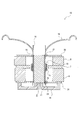
- the embodiment of the present technology speaker device is shown with Drawing 2 thru / or Drawing 36, and this figure is an expanded sectional view of the speaker device of a 1st embodiment.
- It is a conceptual diagram which shows the state of a lead wire.
- It is a conceptual diagram which shows the magnetic circuit and magnetic flux distribution of a speaker apparatus.
- It is a figure which shows the magnetic circuit containing a magnetic gap, and magnetic flux density distribution.
- It is an expanded sectional view of a voice coil.
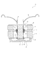
- It is an expanded sectional view which shows the structure of the speaker apparatus of 2nd Embodiment.
- FIG. 24 is a view showing a first modification of the magnetic flux change portion forming a magnetic gradient in the axial direction together with FIG. 24, and this figure is a view showing first to fourth modifications. It is a figure which shows the 5th thru
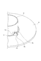
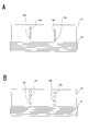
- FIG. 10 is a schematic enlarged perspective view showing a state in which a part of the magnetic fluid is drawn to the side of the magnetic flux changing portion forming a magnetic gradient by changing the magnetic flux density in the circumferential direction when the coil bobbin is changed.
- FIG. 10 is a schematic enlarged perspective view showing a state in which a part of the magnetic fluid is drawn to the side of the magnetic flux changing portion forming a magnetic gradient by changing the magnetic flux density in the circumferential direction when the coil bobbin is changed.
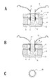
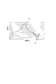
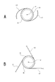
- FIG. 29 is a view showing a modification 2 of the magnetic flux change portion forming a magnetic gradient in the circumferential direction together with FIG. 29, and this figure is a view showing a first modification. It is a figure which shows the 2nd and 3rd modification. The modification 3 of the state which formed the through-hole with FIG. 31 is shown, and this figure is an expanded view which shows a 1st modification. It is an expanded view which shows the 2nd and 3rd modification. It is a conceptual diagram which shows the structure and support ring of a speaker apparatus. It is a graph which shows the magnetic force distribution at the time of mounting
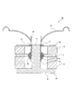
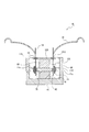
- FIG. 1 is an enlarged cross-sectional view of the speaker device 1 according to the first embodiment.
- the speaker device 1 has a frame 2 that functions as a housing.
- the speaker device 1 is, for example, a woofer that outputs a bass range.
- the frame 2 has a cylindrical portion 3 formed in a substantially cylindrical shape, and a mounting portion 4 protruding outward from the front edge of the cylindrical portion 3 and a connection protruding inward from the rear edge of the cylindrical portion 3 And 5 are included.
- a plurality of communication holes 3a, 3a, ... are formed in the cylindrical portion 3 at regular intervals in the circumferential direction.
- Terminals 6 and 6 are attached to the cylindrical portion 3 at positions 180 ° opposite to each other in the circumferential direction.
- the terminal 6 is provided as a connection portion to be connected to an amplifier (not shown), and has a terminal portion 6a.
- a sub plate 22 made of a magnetic material is attached to the rear surface of the connection portion 5 of the frame 2.
- the sub plate 22 is formed in a thin and substantially annular shape.
- magnets 8, 8 formed in an annular shape are disposed separately in the front and rear direction.
- the front magnet 8 is attached to the rear surface of the sub plate 22, and a main plate 7 made of a magnetic material is attached between the magnets 8 and 8.
- the main plate 7 is formed in a thin and substantially annular shape.
- a yoke 9 is attached to the rear surface of the rear magnet 8.
- the yoke 9 is integrally formed with a disk-shaped base surface portion 10 and a center pole portion 11 projecting forward from a central portion of the base surface portion 10.
- the center pole portion 11 is formed in, for example, a cylindrical shape There is.
- the front surface of the base surface portion 10 of the yoke 9 is attached to the rear surface of the rear magnet 8.
- the main plate 7, the sub plate 22, the magnets 8, 8 and the yoke 9 are coupled with their central axes aligned.
- the front surface of the center pole portion 11 is positioned in the same plane as the front surface of the sub plate 22, and the space between the sub plate 22 and the center pole portion 11 is formed as a sub magnetic gap 21.
- a space between the main plate 7 and the center pole portion 11 is formed as a main magnetic gap 13.
- a coil bobbin 14 is disposed on the outer peripheral side of the center pole portion 11 of the yoke 9 so as to be movable (movable) in the front-rear direction, that is, in the axial direction of the center pole portion 11.
- the coil bobbin 14 is formed in a cylindrical shape, and the voice coil 15 is wound around the outer peripheral surface of the rear end portion of the coil bobbin 14.
- the through holes 14a, 14a, ... are formed in the coil bobbin 14 at equal intervals in the circumferential direction, for example.
- the voice coil 15 is partially located in the main magnetic gap 13.
- the coil bobbin 14 is partially located in the sub magnetic gap 21 and the other is located in the main magnetic gap 13.
- a first magnetic circuit is constituted by the main plate 7, the magnet 8 on the rear side, the base surface portion 10 of the yoke 9 and the center pole portion 11 of the yoke 9, and the main plate 7, the magnet 8 on the front side,
- the sub plate 22 and the center pole portion 11 of the yoke 9 constitute a second magnetic circuit.
- the submagnetic gap 21 is filled with the magnetic fluid 16.
- the coil bobbin 14 is made axially movable (movable) by the action of the magnetic fluid 16.
- Both ends of the voice coil 15 and the terminals 6, 6 are connected by leads 17, 17, respectively.
- the lead wires 17, 17 are attached to the coil bobbin 14 in a state of being disposed symmetrically with respect to the central axis P of the coil bobbin 14 (see FIG. 2).
- the lead wires 17, 17 are, for example, linearly arranged.
- the number of lead wires 17 is arbitrary as long as it is plural, and three or more leads may be provided.
- An annular diaphragm 18 is disposed on the front end side of the frame 2, the outer periphery of the diaphragm 18 is attached to the mounting portion 4 of the frame 2, and the inner periphery is attached to the front end of the coil bobbin 14. Therefore, the diaphragm 18 is vibrated with the outer peripheral portion as a fulcrum along with the fluctuation in the axial direction of the coil bobbin 14 (see FIG. 1).
- a center cap 19 is attached to the inner peripheral portion of the diaphragm 18, and the coil bobbin 14 is closed by the center cap 19 from the front side.
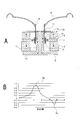
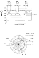
- FIG. 3A is a conceptual diagram showing the magnetic circuit of the speaker device 1
- FIG. 3B is a conceptual diagram showing the magnetic flux distribution of the speaker device 1.
- a first magnetic circuit is formed by the paths of the main plate 7, the rear magnet 8, the base surface 10 of the yoke 9, the center pole 11 of the yoke 9, and the main magnetic gap 13.
- a second magnetic circuit is configured by the paths of the main plate 7, the front magnet 8, the sub plate 22, the sub magnetic gap 21, the center pole portion 11 of the yoke 9, and the main magnetic gap 13.
- the magnetic flux density of the main magnetic gap 13 can be increased as compared with the case of one magnetic circuit.
- the number of magnetic circuits is preferably two.
- the number of magnetic circuits is not limited to two, and may be other numbers.
- the magnetic flux density distribution of the main magnetic gap 13 and the sub magnetic gap 21 in each magnetic circuit is as shown in FIG. 3B.
- the measurement position shown in FIG. 3B includes the main magnetic gap 13 and the sub magnetic gap 21 and indicates each position in the axial direction (front-rear direction) of the center pole portion 11.
- the value Pm of the magnetic flux density is a peak value.
- the value Ps of the magnetic flux density is a peak value.
- the value Ps of the sub magnetic gap 21 is opposite in polarity to the value Pm of the magnetic flux density of the main magnetic gap 13.
- the absolute value of the value Pm of the magnetic flux density is larger than the value Ps of the magnetic flux density.
- FIG. 4B is a conceptual view of a magnetic circuit including a magnetic gap
- FIG. 4A is a view showing a magnetic flux density distribution in the magnetic gap portion.
- a magnetic circuit is formed by the path of the plate 7, the magnetic gap 21, the center pole 11 of the yoke 9, the base surface 10 of the yoke 9, and the magnet 8.
- the magnetic gap 21 is filled with the magnetic fluid 16, and a part of the coil bobbin 14 is positioned in the magnetic gap 21.
- the magnetic flux distribution in the magnetic gap 21 is such that the magnetic flux density is high in the vicinity of the plate 7 on both end sides and in the vicinity of the center pole portion 11, and the magnetic flux density is constant in the other portions. Since the magnetic fluid 16 is attracted to both sides with high magnetic flux density, the nonmagnetic coil bobbin 14 is at the central portion of the plate 7 and the center pole portion 11 by a force acting simultaneously on the coil bobbin 14 from the magnetic fluid 16. Centered on At the same time, the coil bobbin 14 can vibrate linearly in the axial direction (vertical direction in the figure).
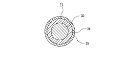
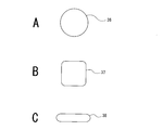
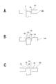
- the wire of the voice coil 15 has a structure in which an insulating coating 34 and a fusion coating 35 are provided on the outer periphery of the conducting wire 33 as shown in FIG. 5, and its cross-sectional shape is round 36 as shown in FIG. (FIG. 6A), square shape 37 (FIG. 6B), ribbon shape 38 (FIG. 6C) and the like, and the diameter is about 0.05 mm to 0.5 mm.
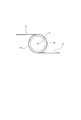
- FIG. 7 shows a state in which the wire of the voice coil 15 is wound around the coil bobbin 14.
- FIG. 7A shows a voice coil 15A in which a round wire 36 is wound around a coil bobbin 14.
- FIG. 7B shows the voice coil 15B in which the square wire 37 is wound around the coil bobbin.
- FIG. 7C shows a voice coil 15C in which a ribbon-shaped wire is wound around the coil bobbin.
- the voice coil 15 Since the voice coil 15 has the wire wound around the coil bobbin 14 a plurality of times, irregularities are formed on the surface side according to the diameter and shape of the wire, and when the voice coil 15 is present in the magnetic fluid 16, This unevenness may cause the magnetic fluid 16 to be scattered in the amplitude direction. For this reason, the filling amount of the magnetic fluid 16 may be reduced, which may interfere with the stable centering of the coil bobbin 14. Further, the magnetic fluid 16 is agitated by the movement of the voice coil 15, so that abnormal noise is generated, which may distort the signal generation noise.
- the speaker device 1 at least two magnetic gaps (sub magnetic gap 21 and main magnetic gap 13) are formed, and a voice wound around the coil bobbin 14 in the main magnetic gap 13 not filled with the magnetic fluid 16.
- the coil 15 is positioned, and the sub magnetic gap 21 in which a portion of the coil bobbin 14 is positioned is filled with the magnetic fluid 16.
- the sub magnetic gap 21 is filled with the magnetic fluid 16, and the coil bobbin 14 is held at this position.
- the coil bobbin 14 is a thin foil-like material (aluminum, polyimide film, etc.), and the surface is finished to be smooth and has no unevenness. For this reason, even if the coil bobbin 14 vibrates, the action of scattering the magnetic fluid 16 is small, and the reduction of the filling amount of the magnetic fluid 16 hardly occurs.
- the reduction of the filling amount of the magnetic fluid 16 is suppressed, the stable centering state of the coil bobbin 14 is secured, the occurrence of abnormal noise is prevented, the acoustic conversion efficiency is improved, and a good signal reproduction noise is obtained.
- the coil bobbin 14 is centered by the magnetic fluid 16, a damper for centering the voice coil 15 is not necessary, and the sound conversion efficiency can be improved by reducing the weight of the speaker device 1.
- the through holes 14a, 14a,... are formed in the coil bobbin 14.
- the through holes 14a, 14a,... are located in the sub magnetic gap 21 where the magnetic fluid 16 is present.
- the magnetic fluid 16 is flowed between the subplate 22 and the center pole portion 11 of the yoke 9 through the through holes 14a, 14a, ..., the magnetic fluid 16 filled in the submagnetic gap 21 is
- the coil bobbins 14 do not separate the inside and the outside. Therefore, good fluidity of the magnetic fluid 16 is secured, the accuracy of centering of the coil bobbin 14 is improved, distortion with respect to the input is sufficiently reduced, and stable signal reproduction operation can be secured.
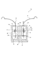
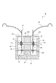
- the speaker devices according to the second to fifteenth embodiments will be described below with reference to FIGS. 8 to 21.
- the speaker devices according to the second to eighth embodiments are of an external magnetic circuit type (external magnetic type).
- the speaker devices according to the ninth to fifteenth embodiments are of the internal magnetic magnetic circuit type (internal magnetic type).
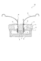
- the speaker device 1A of the second embodiment is the speaker device 1 of the first embodiment in which the main magnetic gap 13 is also filled with the magnetic fluid 16. Thereby, the stability of the amplitude operation of the coil bobbin 14 is increased as compared with that of the magnetic gap filled with the magnetic fluid 16 in one embodiment.
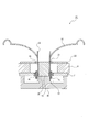
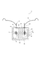
- the speaker device 1B of the third embodiment has one magnetic circuit as compared with the speaker device 1 of the first embodiment. That is, a magnetic circuit is formed on the front side of the support frame 41 formed of a nonmagnetic material.
- the yoke 9 is constituted only by the center pole portion 11 (same in the speaker device 1C to the speaker device 1G described later).
- the speaker device 1B has two magnetic gaps of the main magnetic gap 13 and the sub magnetic gap 21 in the magnetic circuit, and the sub magnetic gap 21 is filled with the magnetic fluid 16 in the same manner. Since the speaker device 1B has only one magnet 8, the structure is simple and downsizing can be achieved.
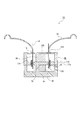
- the speaker device 1C of the fourth embodiment is a speaker device 1B of the third embodiment in which the magnetic fluid 16 is also filled in the main magnetic gap 13. Thereby, the stability of the amplitude operation of the coil bobbin 14 is increased as compared with that of the magnetic gap filled with the magnetic fluid 16 in one embodiment.
- the speaker device 1D of the fifth embodiment is obtained by adding a sub magnetic gap 23 to the sub magnetic gap 21 in the speaker device 1 of the first embodiment.
- the sub magnetic gap 23 is formed between the sub plate 24 and the yoke 9.
- the sub magnetic gap 21 and the sub magnetic gap 23 are formed on the opposite side across the voice coil 15, and the coil bobbin 14 is supported in the sub magnetic gap 21 and the sub magnetic gap 23. Therefore, the coil bobbin 14 is further stabilized. To be centered.
- the main magnetic gap 13 is filled with the magnetic fluid 16 without filling the sub magnetic gap 21 with the magnetic fluid 16 in the speaker device 1D of the fifth embodiment. It is a thing. This also increases the stability of the amplitude operation of the coil bobbin 14 as compared with that of the magnetic gap filled with the magnetic fluid 16 in one embodiment.
- a loudspeaker device 1F according to a seventh embodiment will be described with reference to FIG.
- the speaker device 1F of the seventh embodiment is a speaker device 1D of the fifth embodiment in which the main magnetic gap 13 is also filled with the magnetic fluid 16. This further increases the stability of the amplitude operation of the coil bobbin 14.
- a speaker device 1G of the eighth embodiment is obtained by exchanging the positions of the sub magnetic gap 21 and the main magnetic gap 13 with respect to the speaker device 1B of the third embodiment.
- the main plate 7 is attached to the front surface of the magnet 8 and the sub plate 24 is attached to the rear surface of the magnet 8.
- the submagnetic gap 23 is filled with the magnetic fluid 16.
- the speaker device 1G Since the speaker device 1G has only one magnet 8, the structure is simple and downsizing can be achieved.
- the speaker device 1H includes magnets 8X and 8X, a yoke 9X, and a sub plate 22X.
- the central portion of the yoke 9X is attached to the rear surface of the rear magnet 8X.
- the yoke 9X has a disk-shaped base surface portion 10X and a peripheral surface portion 11X which is protruded forward from the outer peripheral portion of the base surface portion 10X.
- the peripheral surface portion 11X includes a cylindrical portion 11a and a front side flange portion 11b projecting inward from the front end of the cylindrical portion 11a, and a rear side flange portion 11c projecting inward from a central portion in the front and rear direction of the cylindrical portion 11a. It consists of
- the magnets 8X and 8X are formed in a disk shape, and a main plate 7X formed of a magnetic material is attached to the front surface of the rear side magnet 8X.
- the main plate 7X is formed in a thin substantially disk shape.
- a front magnet 8X is attached to the front of the main plate 7X.
- a sub plate 22X made of a magnetic material is attached to the front of the front magnet 8X.
- the sub plate 22X is formed in a thin substantially disk shape.
- the main plate 7X, the subplate 22X, the magnets 8X, 8X, and the base surface 10X of the yoke 9X are coupled in a state where the central axes coincide with each other.
- a space is formed between the main plate 7X and the rear flange portion 11c of the yoke 9X, and this space is formed as a main magnetic gap 13X.
- a space is formed between the subplate 22X and the front flange portion 11b of the yoke 9X, and this space is formed as a submagnetic gap 21X.
- the coil bobbin 14 is disposed on the outer peripheral side of the main plate 7X and the sub plate 22X in a state of being movable (movable) in the front-rear direction.
- the voice coil 15 wound around the coil bobbin 14 is at least partially positioned in the main magnetic gap 13X, and each portion of the coil bobbin 14 is positioned in the main magnetic gap 13X and the sub magnetic gap 21X.
- a first magnetic circuit is configured by the main plate 7X, the rear flange portion 11c of the yoke 9X, the cylindrical portion 11a of the yoke 9X, the base surface portion 10X of the yoke 9X, and the magnet 8X on the rear side.
- a second magnetic circuit is formed by the main plate 7X, the rear flange 11c of the yoke 9X, the cylindrical portion 11a of the yoke 9X, the front flange 11b of the yoke 9X, the subplate 22X, and the magnet 8X on the front.
- the sub magnetic gap 21X is filled with the magnetic fluid 16.
- the voice coil 15 is positioned in the main magnetic gap 13X and the sub magnetic gap 21X is filled with the magnetic fluid 16
- the magnetic fluid 16 is less likely to be scattered when the coil bobbin 14 is changed, and the magnetic The reduction of the filling amount of the fluid 16 does not easily occur, and a stable centering state of the coil bobbin 14 can be secured.
- a magnetic fluid 16 is also filled in the main magnetic gap 13X of the speaker device 1H of the ninth embodiment.
- the stability of the amplitude operation of the coil bobbin 14 is increased as compared with that of the magnetic gap filled with the magnetic fluid 16 in one embodiment.
- one magnetic circuit is added to the speaker device 1H of the ninth embodiment. That is, on the front side of the central portion of the support frame 41, a cylindrical member 42 which is a nonmagnetic material is attached. Furthermore, the yoke 9X is attached to the front side of the support frame 41, and the main plate 7X is attached to the front side of the cylindrical member 42.
- the magnetic circuit includes one magnet 8X, which results in cost reduction.
- a magnetic fluid 16 is also filled in the main magnetic gap 13X of the speaker device 1J of the eleventh embodiment.
- one magnetic gap is added as a sub magnetic gap 23 to the speaker device 1H according to the ninth embodiment, and the sub magnetic gap 23 is filled with the magnetic fluid 16.
- the sub plate 24 is attached to the front side of the support frame 41, and the sub magnetic gap 23 is formed between the sub plate 24 and the yoke 9X.
- the coil bobbin 14 is more stably centered.
- the main magnetic gap 13X is filled with the magnetic fluid 16 without filling the submagnetic gap 21X with the magnetic fluid 16 in the speaker device 1L of the thirteenth embodiment.
- the stability of the amplitude operation of the coil bobbin 14 is increased as compared with the case where the number of sub magnetic gaps filled with the magnetic fluid 16 is one.
- a speaker device 1N according to a fifteenth embodiment will be described with reference to FIG.
- a magnetic fluid 16 is also filled in the main magnetic gap 13X of the speaker device 1L of the thirteenth embodiment.
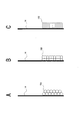
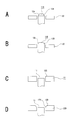
- FIG. 22A shows the case where there is no gradient of the magnetic flux density in the amplitude direction of the sub magnetic gap 21.
- the distribution of the magnetic flux density is approximately symmetrical in the amplitude direction.
- FIG. 22B when the coil bobbin 14 changes in the X direction, the magnetic fluid 16 is easily scattered to the outside.
- the distribution of the magnetic flux density of the sub magnetic gap 21 is in the amplitude direction. It is not symmetrical but has a characteristic of having a gradient Ta. In this case, even if the coil bobbin 14 changes in the X direction due to the gradient Ta and the magnetic fluid 16 is scattered, the magnetic flux density near the inclined surface 12a is high, and the scattered magnetic fluid 16 is drawn to the magnetic gap 21 side. As shown in 22D, a return z occurs and is attracted to the sub magnetic gap 21 to suppress the scattering.
- the magnetic flux change portion according to the modification shown below is formed in the center pole portion 11 of the sub plate 22 or the yoke 19, and hereinafter, only the portions different from the sub plate 22 or the center pole portion 11 will be described.
- the same sub-plate 22 or center pole portion 11 as the above-described speaker device 1 is given the same reference numeral as that of the same portion of the speaker device 1, and the description thereof is omitted.
- the front end portion of the center pole portion 11A is positioned in a state of being protruded forward from the sub plate 22, and the front end portion of the center pole portion 11A is provided as the magnetic flux change portion 12A according to the first modification. It is done.
- the magnetic flux change portion 12A is formed in such a shape that the diameter decreases in the forward direction, and the outer peripheral surface is an inclined surface 12a.
- the front end portion of the center pole portion 11B is positioned in a state of being protruded forward from the sub plate 22, and the front end portion of the center pole portion 11B is provided as a magnetic flux change portion 12B according to the second modification. It is done.
- the magnetic flux change portion 12B is formed in a shape in which the diameter decreases toward the front, and the outer peripheral surface is a curved surface 12b.
- the front surface of the center pole portion 11 is located between the front surface and the rear surface of the sub plate 22. Therefore, the front end portion of the sub plate 22 is positioned forward of the front surface of the center pole portion 11, and the front end portion of the sub plate 22 is provided as the magnetic flux change portion 12C according to the third modification.
- the front surface of the center pole portion 11 is located between the front surface and the rear surface of the sub plate 22D. Therefore, the portion on the front end side of the sub plate 22D is positioned forward of the front surface of the center pole portion 11, and the portion on the front end side of the sub plate 22D is provided as the magnetic flux change portion 12D according to the fourth modification.
- the magnetic flux change portion 12D is formed to be smaller in diameter as it goes forward, and is formed as an inclined surface 12d which is displaced outward as the inner circumferential surface goes forward.
- the front surface of the center pole portion 11 is located between the front surface and the rear surface of the sub plate 22E. Therefore, the front end side portion of the sub plate 22E is positioned forward of the front side of the center pole portion 11, and the front end side portion of the sub plate 22E is provided as the magnetic flux change portion 12E according to the fifth modification.
- the magnetic flux change portion 12E is formed in such a shape that the diameter decreases in the forward direction, and is a curved surface 12e which is displaced outward in the forward direction of the inner peripheral surface.
- the magnetic flux density can be obtained by providing the magnetic flux change portions 12A and 12B and the magnetic flux change portions 12D and 12E on the center pole portions 11A and 11B and the sub plates 22D and 22E as in the sixth and seventh modifications described above.
- the degree of freedom with respect to the change of is increased, and the degree of freedom in design can be improved.
- the curved surfaces 12b and 12e are formed, and the portions on which the curved surfaces 12b and 12e are formed are provided as the magnetic flux change portions 12B and 12E.
- the magnetic gradient can be easily formed while ensuring the simplification of the shape of the center pole portion 11B or the sub plate 22E.
- FIG. 25 shows the cross-sectional structure of the sub plate 22, the sub magnetic gap 21, and the center pole portion 11.
- FIG. 25A shows the case where there is no magnetic force gradient in the circumferential direction. As shown in FIG. 25A, the center pole portion 11 is located at the center position, and the sub magnetic gap 21 and the sub plate 22 are located around it.
- the magnetic flux changing portion 12 (12 A, 12 B,...) Is formed in the center pole portion 11 of the yoke 9.
- the magnetic flux changing portion 12 of the center pole portion 11 has a function of forming a magnetic gradient Ta that changes the magnetic force to the magnetic fluid 16 by changing the magnetic flux density in the axial direction, that is, the fluctuation direction of the coil bobbin 14 (FIG. 22) reference).
- the lowest value Samin (see FIG. 26) of the magnetic flux density in the circumferential direction is larger than a value Tamid (see FIG. 22C) that is half the highest value Tamax (see FIG. 22C) of the magnetic flux density in the axial direction. It is done.
- the portions 16a, 16a,... Of the magnetic fluid 16 to be scattered in the axial direction or the circumferential direction have the magnetic forces Sa, Sa,.
- the sub magnetic gap 21 is attracted from the air gaps 21a, 21a, 21a, which are the portions that it has, and scattering is suppressed.
- the magnetic flux changing portion according to the modification shown below is formed in the center pole portion of the sub plate or yoke, and in the following, only different portions with respect to the sub plate 22 and the center pole portion 11 will be described.
- the same numerals as the numerals attached to the same part in the speaker device 1 are attached, and explanation is omitted.
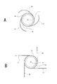
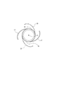
- first Modification As shown in FIG. 28, for example, six concave portions are formed on the inner peripheral surface of the sub plate 22A at equal intervals in the circumferential direction, and these concave portions are magnetic flux changing portions according to the first modification, respectively. 22a, 22a,... The magnetic flux change portions 22a, 22a,... Are formed to extend in the front-rear direction.
- the number of magnetic flux change portions 22a is arbitrary, and may be five or less, or seven or more.
- the magnetic flux change portions 22a each have a cross section perpendicular to the axial direction, for example, formed in a substantially semicircular shape, but may have another shape such as a triangular shape or a rectangular shape.
- Second Modified Example On the outer peripheral surface of the center pole portion 11B, as shown in FIG. 29A, for example, six recessed portions are formed at equal intervals in the circumferential direction, and these recessed portions are magnetic flux changing portions according to the second modification, respectively. It is formed as 11x, 11x,.
- the magnetic flux change portions 11x, 11x,... Are formed to extend in the front-rear direction. No magnetic flux change portion is formed on the sub plate 22.
- the number of the magnetic flux change parts 11x is arbitrary, may be five or less, or seven or more.
- the magnetic flux change portion 11x has a cross section perpendicular to the axial direction, for example, formed in a substantially semicircular shape, but may have another shape such as a triangular shape or a square shape.
- the sub plate 22A and the center pole portion 11A are combined, and as shown in FIG. 29B, the magnetic flux changing portions 22a, 22a, 22a and the circumferential portions separated at equal intervals are circumferentially It comprises magnetic flux change portions 11x, 11x, 11x formed at equal intervals in the direction.
- the magnetic flux change portions 22a, 22a, 22a and the magnetic flux change portions 11x, 11x, 11x are alternately positioned in the circumferential direction.
- the number of the magnetic flux change portions 22a and the number of the magnetic flux change portions 11x are arbitrary, may be two or less, or four or more.
- the magnetic flux change portions 22a and the magnetic flux change portions 11x are each formed, for example, in a substantially semicircular shape in cross section perpendicular to the axial direction, but may be another shape such as a triangular shape or a square shape. .
- the degree of freedom with respect to the change in magnetic flux density is increased.
- the degree of improvement can be achieved.
- the magnetic flux changing portions 22a, 22a, 22a formed on the inner peripheral surface of the sub plate 22A and the magnetic flux changing portions 11x, 11x, 11x formed on the outer peripheral surface of the center pole portion 11A are alternately positioned in the circumferential direction.
- the magnetic flux change portions 11x, 11x,... Have symmetry, so that a good magnetic balance is ensured, and the coil bobbin 14 can be smoothly varied.
- the recesses extending in the axial direction are formed as the magnetic flux changing portions 22a, 22a, ... and the magnetic flux changing portions 11x, 11x, ..., the magnetic flux changing portions 11x, 11x, ..., and the magnetic flux changing portions
- the formation of 11x, 11x,... Is easy, and the speaker device 1 can be miniaturized without the outer diameter of the speaker device 1 becoming large.
- the through holes 14a, 14a,... (See FIG. 1) formed in the coil bobbin 14 flow of the magnetic fluid 16 between the subplate 22 and the center pole portion 11 in the range of fluctuation in the axial direction to the coil bobbin 14. It is desirable to form in the position which permits The allowable position is the position where the through holes 14a, 14a,... Always exist at the position where the magnetic fluid 16 exists, even if the coil bobbin 14 changes in the axial direction.
- the formation of the through holes 14a allows the magnetic fluid 16 to flow between the subplate 22 and the center pole portion 11 of the yoke 9 through the through holes 14a, so that the flow of the magnetic fluid 16 is good.
- the accuracy of the centering of the coil bobbin 14 is improved, the distortion with respect to the input is sufficiently reduced, and a stable signal reproduction operation can be ensured.
- the shape of the through holes 14a, 14a, ... may be any shape such as a round shape, an angular shape, a slit shape, a curved slit shape and the like.
- the plurality of through holes 14b, 14b,... And the plurality of through holes 14c, 14c, are formed to be separated in the axial direction.
- the through holes 14b, 14b, ... and the through holes 14c, 14c, ... are formed, for example, in a rectangular shape.
- the through holes 14b, 14b, ... and the through holes 14c, 14c, ... are formed to be offset in the axial direction, whereby the through holes 14b, 14b, ... or the through holes 14c, 14c, ...
- the magnetic fluid 16 is more likely to flow because at least one of the two is at a position where the magnetic fluid 16 is present.
- the plurality of through holes 14d, 14d,... And the plurality of through holes 14e, 14e, are formed in the shape of a slit extending in the axial direction.
- the through holes 14d, 14d, ..., 14e, 14e, ... are formed in a slit shape extending in the axial direction, when the coil bobbin 14 is moved in the axial direction The magnetic fluid 16 is more likely to flow through any of the through holes 14d, 14d,... Or the through holes 14e, 14e,.
- the magnetic fluid 16 flows through either the through holes 14f, 14f, ... or the through holes 14g, 14g, ...
- the through holes 14f, 14f, ..., 14g, 14g, ... are formed in a circular shape, the through holes 14f, 14f, ..., 14g, 14g, ... Stress concentration hardly occurs at the opening edge, and high rigidity of the coil bobbin 14 can be secured.
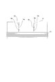
- FIG. 32A is a conceptual view showing the configuration of the speaker device 1 in which the support ring 25 is not mounted
- FIG. 32B is a conceptual view showing the configuration of the speaker device 1 in which the support ring 25 is mounted.
- the coil bobbin 14 When the coil bobbin 14 is mounted in assembling the speaker device 1, the coil bobbin 14 is inserted from the front side of the speaker device 1 into the sub plate 22 and mounted.
- the radius of the central portion of the sub plate 22 is made larger than the outer circumference (outer diameter) of the voice coil 15.
- the voice coil 15 can smoothly pass through the sub magnetic gap 21 formed on the inner peripheral side of the sub plate 22.
- the center hole of the sub plate 22 becomes large, and the coil bobbin 14 can be attached smoothly.
- the lowering of the magnetic flux density to be held may make the holding function for the magnetic fluid 16 unstable and the centering effect of the coil bobbin 14 may be insufficient.
- the filling amount of the magnetic fluid 16 is increased, and the production cost is also increased.
- the support ring 25 is attached to the inner peripheral portion of the sub plate 22 to reduce the sub magnetic gap 21. be able to.
- the support ring 25 is preferably a magnetic material. By forming the support ring 25 of a magnetic material, the value of the magnetic flux density of the sub magnetic gap 21 can be raised to the peak value 40 (see FIG. 33).
- the peak value 39 shown in FIG. 33 is the value of the magnetic flux density of the main magnetic gap 13.
- the support ring 25 may be made of a nonmagnetic material. In this case, although there is no effect of increasing the magnetic flux density, it is possible to improve the stability of the centering effect of the coil bobbin 14 and reduce the filling amount of the magnetic fluid 16.
- both ends of the voice coil 15 and the terminals 6, 6 are connected by the lead wires 17, 17 (see FIG. 2).
- the lead wires 17 and 17 are attached to the coil bobbin 14 in a state of being arranged symmetrically with respect to the coil bobbin 14 with reference to the central axis P of the coil bobbin 14.
- the lead wires 17, 17 are, for example, linearly arranged.
- the number of lead wires 17 is arbitrary as long as it is plural, and three or more leads may be provided.
- the two lead wires 17 and 17 are attached to the coil bobbin 14 in a state of being arranged symmetrically with respect to the coil bobbin 14 with reference to the central axis P of the coil bobbin 14
- the lead wires 17, 17 are arranged in a curved shape. Note that three or more lead wires 17 may be disposed as long as they are disposed symmetrically with respect to the central axis P of the coil bobbin 14.
- the two lead wires 17 and 17 and one connecting wire 20 are equiangular (symmetrical) with respect to the coil bobbin 14 with respect to the central axis P of the coil bobbin 14.
- the lead wires 17, 17 and the connecting wire 20 are arranged in a straight line in a state of being disposed in the coil bobbin 14.
- connection wire 20 is made of, for example, the same material as the lead wire 17, and both ends thereof are attached to the frame 2 and the coil bobbin 14, respectively.
- the connection wire 20 may have a function of supplying current to the voice coil 15 as well as the lead wire 17.
- two lead wires 17 and 17 and one connecting wire 20 are equiangular (symmetrical) with respect to the coil bobbin 14 with respect to the central axis P of the coil bobbin 14.
- the lead wires 17, 17 and the connecting wire 20 are arranged in a curved shape, and are attached to the coil bobbin 14 in a state of being arranged in the above.
- connection wire 20 is made of, for example, the same material as the lead wire 17, and both ends thereof are attached to the frame 2 and the coil bobbin 14, respectively.
- the connection wire 20 may have a function of supplying current to the voice coil 15 as well as the lead wire 17.
- the two lead wires 17 and 17 and the two connection wires 20 and 20 are at equal angles with respect to the coil bobbin 14 with respect to the central axis P of the coil bobbin 14. It is attached to the coil bobbin 14 in the disposed state, and the lead wires 17, 17 and the connecting wires 20, 20 are arranged in a straight line.
- connection wire 20 is made of, for example, the same material as the lead wire 17, and both ends thereof are attached to the frame 2 and the coil bobbin 14, respectively.
- the connection wire 20 may have a function of supplying current to the voice coil 15 as well as the lead wire 17. Further, three or more connection wires 20 may be disposed as long as they are disposed symmetrically with respect to the central axis P of the coil bobbin 14 with respect to the coil bobbin 14 together with the lead wires 17 and 17.
- the two lead wires 17, 17 and the two connection wires 20, 20 are equiangular to the coil bobbin 14 with respect to the central axis P of the coil bobbin 14. It is attached to the coil bobbin 14 in the arranged state, and the lead wires 17, 17 and the connecting wires 20, 20 are arranged in a curved shape.
- connection wire 20 is made of, for example, the same material as the lead wire 17, and both ends thereof are attached to the frame 2 and the coil bobbin 14, respectively.
- the connection wire 20 may have a function of supplying current to the voice coil 15 as well as the lead wire 17. Further, three or more connection wires 20 may be disposed as long as they are disposed symmetrically with respect to the central axis P of the coil bobbin 14 with respect to the coil bobbin 14 together with the lead wires 17 and 17.
- the lead wires 17 and 17 and the at least one connecting wire 20 are arranged equiangularly (symmetrically) with respect to the central axis P of the coil bobbin 14
- the sub magnetic gap 21 and the main magnetic gap 13 are formed, and the magnetic flux 16 is filled in the sub magnetic gap 21 to hold the coil bobbin 14. Further, a through hole 14 a is formed in the coil bobbin 14.
- the flow of the magnetic fluid 16 in the sub magnetic gap 21 is facilitated, the stirring thereof is suppressed, and the centering effect to keep the coil bobbin 14 at the center position in the sub magnetic gap 21 is stabilized, and the acoustic conversion efficiency is improved. It is possible to improve and improve the sound quality.
- a magnetic gradient is formed to change the magnetic force with respect to the magnetic fluid 16 by changing the magnetic flux density in the circumferential direction of the center pole portion 11.
- the magnetic fluid 16 is not scattered from the sub magnetic gap 21 when the coil bobbin 14 is changed, the filling amount of the magnetic fluid 16 in the sub magnetic gap 21 is not reduced, and the magnetic fluid 16 is not agitated. It is possible to improve and improve the sound quality.
- the magnetic flux density is changed also in the axial direction of the center pole portion 11 to form a magnetic gradient for changing the magnetic force with respect to the magnetic fluid 16. Therefore, the acoustic conversion efficiency is further improved and the sound quality is further improved. Can.
- the minimum value Samin of the magnetic flux density in the circumferential direction is larger than a half value of the maximum value Tamax of the magnetic flux density in the axial direction, the magnetic fluid 16 to be scattered when the coil bobbin 14 fluctuates the air gap 21a. , 21a,..., The sub magnetic gap 21 is reliably held, and scattering of the magnetic fluid 16 can be reliably prevented.
- the magnetic fluid 16 has a saturation magnetic flux of 30 to 40 mT and a viscosity of 300 cp or less, scattering is prevented and fluctuation of the coil bobbin 14 is not suppressed by the magnetic fluid 16. Good output of reproduced sound can be secured.
- magnetic flux change portions 12, 12A, 12B or magnetic flux change portions 12C which form a magnetic gradient in the axial direction of the center pole portions 11, 11A, 11B in the sub plates 22, 22D, 22E or the center pole portions 11, 11A, 11B.
- 12D, 12E the structure of the subplate 22, 22D, 22E or the center pole portion 11, 11A, 11B does not become complicated, and simplification of the structure is ensured to improve the sound conversion efficiency and the sound quality. It can improve.
- the magnetic flux changing portion 12 is made by causing the tip of the center pole portion 11, 11A, 11B to axially protrude from the sub plate 22 or positioning the front surface of the center pole portion 11 rearward from the front surface of the sub plate 22, 22D, 22E. , 12A, 12C, 12D, and 12E, the magnetic flux change portions 12, 12A, 12B, 12C, 12D, and 12E can be easily provided.
- the support ring is attached to the inner periphery of the sub plate, the stability of the centering effect can be improved.
- the main magnetic gap 13 be positioned closer to the diaphragm 18 than the sub magnetic gap 21.
- the voice coil 15 is positioned closer to the diaphragm 18, the coil bobbin 14 is assembled. It is not necessary to enlarge the sub magnetic gap 21 for (at the time of insertion), and the magnetic flux density can be improved.
- the present technology can also adopt the following configuration.
- a speaker device is provided with a through hole located in the sub magnetic gap filled with the magnetic fluid in the coil bobbin.
- the through hole is formed at a position allowing the flow of the magnetic fluid between the sub plate and the yoke in the range of fluctuation of the coil bobbin in the axial direction.
- a plurality of the through holes are formed in the circumferential direction of the coil bobbin so as to be separated from each other.
- the through holes have a slit shape extending in the axial direction of the coil bobbin, and a plurality of the through holes are formed separately in the circumferential direction of the coil bobbin,
- the speaker device according to any one of (1) to (5), wherein positions of the plurality of through holes are shifted in the axial direction.
- the sub magnetic gap is positioned closer to the diaphragm than the main magnetic gap;
- a support ring is attached to the inner periphery of the sub plate,
- the speaker apparatus according to any one of (1) to (7), wherein at least a part of the support ring is positioned inside the inner circumferential surface of the sub plate.
- An inclined surface which is inclined with respect to the axial direction is formed on the surface of the sub plate or the yoke, and a portion in which the inclined surface is formed is provided as the magnetic flux change portion according to (11) or (12). Speaker device.
- a plurality of lead wires connected to the voice coil are provided, The speaker device according to any one of (1) to (17), wherein the plurality of lead wires are arranged symmetrically with respect to a central axis of the coil bobbin.
Landscapes
- Engineering & Computer Science (AREA)
- Physics & Mathematics (AREA)
- Acoustics & Sound (AREA)
- Signal Processing (AREA)
- Multimedia (AREA)
- Audible-Bandwidth Dynamoelectric Transducers Other Than Pickups (AREA)
Abstract
Description
図1により第1の実施の形態にかかるスピーカ装置1の具体的構成について説明する。ここでの説明においては、スピーカ装置1が向く方向を前方として上下前後左右の方向を示す。
以下に、スピーカ装置1の磁気回路と磁束分布について図3を参照して説明する。図3Aはスピーカ装置1の磁気回路を表す概念図であり、図3Bはスピーカ装置1の磁束分布を表す概念図である。
以下に、磁性流体の作用について図4を参照して説明する。図4Bは磁気ギャップを含む磁気回路の概念図であり、図4Aは磁気ギャップ部分の磁束密度分布を表す図である。図4Bに示すように、プレート7、磁気ギャップ21、ヨーク9のセンターポール部11、ヨーク9のベース面部10、マグネット8の経路で磁気回路を形成した場合を考える。
以下に、ボイスコイル15の形状と磁性流体16の関係について説明する(図5乃至図7参照)。
以下に、第2の実施の形態乃至第15の実施の形態のスピーカ装置について図8乃至図21を参照して説明する。ここで、第2の実施の形態乃至第8の実施の形態のスピーカ装置は外磁磁気回路形式(外磁型)のものである。第9の実施の形態乃至第15の実施の形態のスピーカ装置は内磁磁気回路形式(内磁型)のものである。
第2の実施の形態のスピーカ装置1Aについて図8を参照して説明する。
第3の実施の形態のスピーカ装置1Bについて図9を参照して説明する。
第4の実施の形態のスピーカ装置1Cについて図10を参照して説明する。
第5の実施の形態のスピーカ装置1Dについて図11を参照して説明する。
第6の実施の形態のスピーカ装置1Eについて図12を参照して説明する。
第7の実施の形態のスピーカ装置1Fについて図13を参照して説明する。
第8の実施の形態のスピーカ装置1Gについて図14を参照して説明する。
第9の実施の形態のスピーカ装置1Hについて図15を参照して説明する。
第10の実施の形態のスピーカ装置1Iについて図16を参照して説明する。
これにより、磁性流体16を充填した磁気ギャップが一つの形態のものと比較してコイルボビン14の振幅動作の安定性が増す。
第11の実施の形態のスピーカ装置1Jについて図17を参照して説明する。
第12の実施の形態のスピーカ装置1Kについて図18を参照して説明する。
第13の実施の形態のスピーカ装置1Lについて図19を参照して説明する。
第14の実施の形態のスピーカ装置1Mについて図20を参照して説明する。
第15の実施の形態のスピーカ装置1Nについて図21を参照して説明する。
以下に、サブ磁気ギャップ21に保持されているコイルボビン14の軸方向における振幅に対し軸方向における磁力勾配と磁性流体16の動作との関係について図22を参照して説明する。
次に、ヨーク9のセンターポール部11の軸方向において磁気勾配を形成する磁束変化部の各変形例について図23及び図24を参照して説明する。
図23Aに示すように、センターポール部11Aの前端部がサブプレート22から前方へ突出された状態で位置され、センターポール部11Aの前端部は第1の変形例に係る磁束変化部12Aとして設けられている。磁束変化部12Aは前方へ行くに従って径が小さくなる形状に形成され、外周面が傾斜面12aとされている。
図23Bに示すように、センターポール部11Bの前端部がサブプレート22から前方へ突出された状態で位置され、センターポール部11Bの前端部は第2の変形例に係る磁束変化部12Bとして設けられている。磁束変化部12Bは前方へ行くに従って径が小さくなる形状に形成され、外周面が曲面12bとされている。
図23Cに示すように、センターポール部11の前面がサブプレート22の前面と後面の間に位置されている。従って、サブプレート22の前端側の部分がセンターポール部11の前面より前側に位置され、サブプレート22の前端側の部分が第3の変形例に係る磁束変化部12Cとして設けられている。
図23Dに示すように、センターポール部11の前面がサブプレート22Dの前面と後面の間に位置されている。従って、サブプレート22Dの前端側の部分がセンターポール部11の前面より前側に位置され、サブプレート22Dの前端側の部分が第4の変形例に係る磁束変化部12Dとして設けられている。磁束変化部12Dは前方へ行くに従って径が小さくなる形状に形成され、内周面が前方へ行くに従って外方へ変位する傾斜面12dとされている。
図24Aに示すように、センターポール部11の前面がサブプレート22Eの前面と後面の間に位置されている。従って、サブプレート22Eの前端側の部分がセンターポール部11の前面より前側に位置され、サブプレート22Eの前端側の部分が第5の変形例に係る磁束変化部12Eとして設けられている。磁束変化部12Eは前方へ行くに従って径が小さくなる形状に形成され、内周面が前方へ行くに従って外方へ変位する曲面12eとされている。
第6の変形例は、図24Bに示すように、センターポール部11Aとサブプレート22Dが組み合わされて構成され、センターポール部11Aの前面がサブプレート22Dの前面と同一平面上に位置され、磁束変化部12Aと磁束変化部12Dから成る。
第7の変形例は、図24Cに示すように、センターポール部11Bとサブプレート22Eが組み合わされて構成され、センターポール部11Bの前面がサブプレート22Eの前面と同一平面上に位置され、磁束変化部12Bと磁束変化部12Eから成る。
上記した第1の変形例、第4の変形例及び第6の変形例のように、傾斜面12a、12dを形成し傾斜面12a、12dが形成された部分を磁束変化部12A、12Dとして設けることにより、センターポール部11A又はサブプレート22Dの形状の簡素化を確保した上で磁気勾配を簡単に形成することができる。
以下に、サブ磁気ギャップ21の周方向における磁力勾配と磁性流体16の飛散との関係について図25乃至図27を参照して説明する。
スピーカ装置1にあっては、上記したように、ヨーク9のセンターポール部11に磁束変化部12(12A、12B、・・・)が形成されている態様がある。センターポール部11の磁束変化部12は磁束密度を軸方向、即ち、コイルボビン14の変動方向において変化させて磁性流体16に対する磁力を変化させる磁気勾配Taを形成する機能を有している(図22参照)。
以下に、ヨークのセンターポール部の周方向において磁気勾配を形成する磁束変化部の各変形例について図28及び図29を参照して説明する。
サブプレート22Aの内周面には、図28に示すように、例えば、六つの凹部が周方向に等間隔に離隔して形成され、これらの凹部がそれぞれ第1の変形例に係る磁束変化部22a、22a、・・・として形成されている。磁束変化部22a、22a、・・・はそれぞれ前後方向に延びる状態で形成されている。
センターポール部11Bの外周面には、図29Aに示すように、例えば、六つの凹部が周方向に等間隔に離隔して形成され、これらの凹部がそれぞれ第2の変形例に係る磁束変化部11x、11x、・・・として形成されている。磁束変化部11x、11x、・・・はそれぞれ前後方向に延びる状態で形成されている。サブプレート22には磁束変化部が形成されていない。
第3の変形例はサブプレート22Aとセンターポール部11Aが組み合わされて構成され、図29Bに示すように、周方向に等間隔に離隔して形成された磁束変化部22a、22a、22aと周方向に等間隔に離隔して形成された磁束変化部11x、11x、11xとから成る。磁束変化部22a、22a、22aと磁束変化部11x、11x、11xは周方向において交互に位置されている。
上記したように、磁束変化部22a、22a、・・・又は磁束変化部11x、11x、・・・を周方向に離隔して等間隔に複数形成することにより、磁束変化部22a、22a、・・・又は磁束変化部11x、11x、・・・が対称性を有するため良好な磁気的バランスが確保され、コイルボビン14を円滑に変動させることができる。
コイルボビン14に形成された貫通孔14a、14a、・・・(図1参照)は、コイルボビン14への軸方向への変動範囲においてサブプレート22とセンタポール部11との間の磁性流体16の流動を許容する位置に形成されていることが望ましい。許容する位置とはコイルボビン14が軸方向に変動しても、磁性流体16が存在する位置に必ず貫通孔14a、14a、・・・が存在する位置のことである。
次に、コイルボビン14に形成された貫通孔に関する各変形例について説明する。
第1の変形例は、図30に示すように、複数の貫通孔14b、14b、・・・と複数の貫通孔14c、14c、・・・とがそれぞれコイルボビン14の軸方向に、例えば、等間隔に離隔して位置され、かつ、貫通孔14b、14b、・・・と貫通孔14c、14c、・・・が軸方向においてずれて形成されているものである。貫通孔14b、14b、・・・と貫通孔14c、14c、・・・は、例えば、矩形状に形成されている。
第2の変形例は、図31Aに示すように、複数の貫通孔14d、14d、・・・と複数の貫通孔14e、14e、・・・とがそれぞれコイルボビン14の軸方向に、例えば、等間隔に離隔して位置され、かつ、貫通孔14d、14d、・・・と貫通孔14e、14e、・・・が軸方向においてずれて形成され、貫通孔14d、14d、・・・、14e、14e、・・・が軸方向に延びるスリット形状に形成されたものである。
第3の変形例は、図31Bに示すように、複数の貫通孔14f、14f、・・・と複数の貫通孔14g、14g、・・・とがそれぞれコイルボビン14の軸方向に、例えば、等間隔に離隔して位置され、かつ、貫通孔14f、14f、・・・と貫通孔14g、14g、・・・が軸方向においてずれて形成され、貫通孔14f、14f、・・・、14g、14g、・・・が円形状に形成されたものである。
以下に、サブプレート22に装着されるサポートリング25について図32及び図33を参照して説明する。
上記したように、ボイスコイル15の両端部とターミナル6、6はそれぞれリード線17、17によって接続されている(図2参照)。リード線17、17はコイルボビン14に対してコイルボビン14の中心軸Pを基準として対称に配置された状態でコイルボビン14に取り付けられている。リード線17、17は、例えば、直線状に配置されている。
次に、リード線等のコイルボビンに対する配置状態に関する各変形例について図34乃至図36を参照して説明する。
第1の変形例は、図34Aに示すように、2本のリード線17、17がコイルボビン14に対してコイルボビン14の中心軸Pを基準として対称に配置された状態でコイルボビン14に取り付けられ、リード線17、17が曲線状に配置されている。尚、リード線17はコイルボビン14の中心軸Pを基準として対称に配置されていれば3本以上が配置されていてもよい。
第2の変形例は、図34Bに示すように、2本のリード線17、17と1本の接続線20とがコイルボビン14に対してコイルボビン14の中心軸Pを基準として等角度(対称)に配置された状態でコイルボビン14に取り付けられ、リード線17、17と接続線20が直線状に配置されている。
第3の変形例は、図35Aに示すように、2本のリード線17、17と1本の接続線20とがコイルボビン14に対してコイルボビン14の中心軸Pを基準として等角度(対称)に配置された状態でコイルボビン14に取り付けられ、リード線17、17と接続線20が曲線状に配置されている。
第4の変形例は、図35Bに示すように、2本のリード線17、17と2本の接続線20、20とがコイルボビン14に対してコイルボビン14の中心軸Pを基準として等角度に配置された状態でコイルボビン14に取り付けられ、リード線17、17と接続線20、20が直線状に配置されている。
第5の変形例は、図36に示すように、2本のリード線17、17と2本の接続線20、20とがコイルボビン14に対してコイルボビン14の中心軸Pを基準として等角度に配置された状態でコイルボビン14に取り付けられ、リード線17、17と接続線20、20が曲線状に配置されている。
以上に記載した通り、スピーカ装置1においては、サブ磁気ギャップ21とメイン磁気ギャップ13を形成し、サブ磁気ギャップ21に磁性流体16を充填してコイルボビン14を保持している。また、コイルボビン14には貫通孔14aが形成されている。
中心軸を有するマグネットと、
中心軸を有し前記中心軸が前記マグネットの中心軸に一致され前記マグネットが取り付けられたヨークと、
前記マグネットに取り付けられたメインプレートと、
前記マグネットに取り付けられ前記中心軸の軸方向において前記メインプレートと離隔して位置された少なくとも一つのサブプレートと、
筒状に形成され前記軸方向へ変動可能にされたコイルボビンと、
前記コイルボビンの外周面に巻き付けられ少なくとも一部が前記メインプレートと前記ヨークの間に形成されたメイン磁気ギャップに配置されたボイスコイルと、
内周部が前記コイルボビンに連結され前記コイルボビンの変動に伴って振動される振動板と、
前記サブプレートと前記ヨークの間に形成された少なくとも一つのサブ磁気ギャップに充填された磁性流体とを備え、
前記コイルボビンには前記磁性流体が充填された前記サブ磁気ギャップに位置する貫通孔が形成されている
スピーカ装置。
前記軸方向において磁束密度を変化させて前記磁性流体に対する磁力を変化させる磁気勾配を形成するようにした
前記(1)に記載のスピーカ装置。
前記中心軸の周方向において磁束密度を変化させて前記磁性流体に対する磁力を変化させる磁気勾配を形成するようにした
前記(1)又は前記(2)の何れかに記載のスピーカ装置。
前記貫通孔は、前記コイルボビンの前記軸方向への変動範囲において前記サブプレートと前記ヨークの間の前記磁性流体の流動を許容する位置に形成されている
前記(1)から前記(3)の何れかに記載のスピーカ装置。
前記貫通孔が前記コイルボビンの周方向に離隔して複数形成され、
前記複数の貫通孔の位置が前記軸方向においてずれている
前記(1)から前記(4)の何れかに記載のスピーカ装置。
前記貫通孔が前記コイルボビンの軸方向に延びるスリット形状であり、前記コイルボビンの周方向に離隔して複数形成され、
前記複数の貫通孔の位置が前記軸方向においてずれている
前記(1)から前記(5)の何れかに記載のスピーカ装置。
前記メイン磁気ギャップが前記サブ磁気ギャップより前記振動板側に位置された
前記(1)から前記(6)の何れかに記載のスピーカ装置。
前記サブ磁気ギャップが前記メイン磁気ギャップより前記振動板側に位置され、
前記サブプレートの内周部にサポートリングが取り付けられ、
前記サポートリングは少なくとも一部が前記サブプレートの内周面より内側に位置されている
前記(1)から前記(7)の何れかに記載のスピーカ装置。
前記サポートリングが磁性体である
前記(8)に記載のスピーカ装置。
前記磁性流体は飽和磁束が30mT~40mTにされ粘度が300cp以下にされた
前記(1)から前記(9)の何れかに記載のスピーカ装置。
前記サブプレート又は前記ヨークに前記軸方向において前記磁気勾配を形成する磁束変化部を設けた
前記(3)から前記(10)の何れかに記載のスピーカ装置。
前記ヨークの先端部を前記サブプレートから前記軸方向へ突出させて前記先端部を前記磁束変化部として設けた
前記(11)に記載のスピーカ装置。
前記サブプレート又は前記ヨークの表面に前記軸方向に対して傾斜する傾斜面を形成し前記傾斜面が形成された部分を前記磁束変化部として設けた
前記(11)又は前記(12)に記載のスピーカ装置。
前記サブプレート又は前記ヨークの表面に曲面を形成し前記曲面が形成された部分を前記磁束変化部として設けた
前記(11)から前記(13)の何れかに記載のスピーカ装置。
前記サブプレート及び前記ヨークに前記軸方向において前記磁気勾配を形成する磁束変化部を設けた
前記(3)から前記(10)の何れかに記載のスピーカ装置。
前記サブプレート及び前記ヨークの表面にそれぞれ前記軸方向に対して傾斜する傾斜面を形成し前記傾斜面が形成された部分をそれぞれ前記磁束変化部として設けた
前記(15)に記載のスピーカ装置。
前記サブプレート又は前記ヨークの表面にそれぞれ曲面を形成し前記曲面が形成された部分をそれぞれ前記磁束変化部として設けた
前記(15)又は前記(16)に記載のスピーカ装置。
前記ボイスコイルに接続される複数のリード線が設けられ、
前記複数のリード線を前記コイルボビンの中心軸を基準として対称に配置した
前記(1)から前記(17)の何れかに記載のスピーカ装置。
前記ボイスコイルに接続される複数のリード線と、
前記コイルボビンに接続される少なくとも1本の接続線とが設けられ、
前記複数のリード線と前記接続線を前記中心軸を基準として対称に配置した
前記(1)から前記(18)の何れかに記載のスピーカ装置。
Claims (19)
- 中心軸を有するマグネットと、
中心軸を有し前記中心軸が前記マグネットの中心軸に一致され前記マグネットが取り付けられたヨークと、
前記マグネットに取り付けられたメインプレートと、
前記マグネットに取り付けられ前記中心軸の軸方向において前記メインプレートと離隔して位置された少なくとも一つのサブプレートと、
筒状に形成され前記軸方向へ変動可能にされたコイルボビンと、
前記コイルボビンの外周面に巻き付けられ少なくとも一部が前記メインプレートと前記ヨークの間に形成されたメイン磁気ギャップに配置されたボイスコイルと、
内周部が前記コイルボビンに連結され前記コイルボビンの変動に伴って振動される振動板と、
前記サブプレートと前記ヨークの間に形成された少なくとも一つのサブ磁気ギャップに充填された磁性流体とを備え、
前記コイルボビンには前記磁性流体が充填された前記サブ磁気ギャップに位置する貫通孔が形成されている
スピーカ装置。 - 前記軸方向において磁束密度を変化させて前記磁性流体に対する磁力を変化させる磁気勾配を形成するようにした
請求項1に記載のスピーカ装置。 - 前記中心軸の周方向において磁束密度を変化させて前記磁性流体に対する磁力を変化させる磁気勾配を形成するようにした
請求項1に記載のスピーカ装置。 - 前記貫通孔は、前記コイルボビンの前記軸方向への変動範囲において前記サブプレートと前記ヨークの間の前記磁性流体の流動を許容する位置に形成されている
請求項1に記載のスピーカ装置。 - 前記貫通孔が前記コイルボビンの周方向に離隔して複数形成され、
前記複数の貫通孔の位置が前記軸方向においてずれている
請求項1に記載のスピーカ装置。 - 前記貫通孔が前記コイルボビンの軸方向に延びるスリット形状であり、前記コイルボビンの周方向に離隔して複数形成され、
前記複数の貫通孔の位置が前記軸方向においてずれている
請求項1に記載のスピーカ装置。 - 前記メイン磁気ギャップが前記サブ磁気ギャップより前記振動板側に位置された
請求項1に記載のスピーカ装置。 - 前記サブ磁気ギャップが前記メイン磁気ギャップより前記振動板側に位置され、
前記サブプレートの内周部にサポートリングが取り付けられ、
前記サポートリングは少なくとも一部が前記サブプレートの内周面より内側に位置されている
請求項1に記載のスピーカ装置。 - 前記サポートリングが磁性体である
請求項8に記載のスピーカ装置。 - 前記磁性流体は飽和磁束が30mT~40mTにされ粘度が300cp以下にされた
請求項1に記載のスピーカ装置。 - 前記サブプレート又は前記ヨークに前記軸方向において前記磁気勾配を形成する磁束変化部を設けた
請求項3に記載のスピーカ装置。 - 前記ヨークの先端部を前記サブプレートから前記軸方向へ突出させて前記先端部を前記磁束変化部として設けた
請求項11に記載のスピーカ装置。 - 前記サブプレート又は前記ヨークの表面に前記軸方向に対して傾斜する傾斜面を形成し前記傾斜面が形成された部分を前記磁束変化部として設けた
請求項11に記載のスピーカ装置。 - 前記サブプレート又は前記ヨークの表面に曲面を形成し前記曲面が形成された部分を前記磁束変化部として設けた
請求項11に記載のスピーカ装置。 - 前記サブプレート及び前記ヨークに前記軸方向において前記磁気勾配を形成する磁束変化部を設けた
請求項3に記載のスピーカ装置。 - 前記サブプレート及び前記ヨークの表面にそれぞれ前記軸方向に対して傾斜する傾斜面を形成し前記傾斜面が形成された部分をそれぞれ前記磁束変化部として設けた
請求項15に記載のスピーカ装置。 - 前記サブプレート又は前記ヨークの表面にそれぞれ曲面を形成し前記曲面が形成された部分をそれぞれ前記磁束変化部として設けた
請求項15に記載のスピーカ装置。 - 前記ボイスコイルに接続される複数のリード線が設けられ、
前記複数のリード線を前記コイルボビンの中心軸を基準として対称に配置した
請求項1に記載のスピーカ装置。 - 前記ボイスコイルに接続される複数のリード線と、
前記コイルボビンに接続される少なくとも1本の接続線とが設けられ、
前記複数のリード線と前記接続線を前記中心軸を基準として対称に配置した
請求項1に記載のスピーカ装置。
Priority Applications (4)
| Application Number | Priority Date | Filing Date | Title |
|---|---|---|---|
| US15/106,964 US10111007B2 (en) | 2014-01-28 | 2015-01-15 | Speaker device |
| JP2015559862A JP6497324B2 (ja) | 2014-01-28 | 2015-01-15 | スピーカ装置 |
| CN201580003241.4A CN105850152B (zh) | 2014-01-28 | 2015-01-15 | 扬声器设备 |
| EP15743795.5A EP3073763B1 (en) | 2014-01-28 | 2015-01-15 | Speaker device |
Applications Claiming Priority (2)
| Application Number | Priority Date | Filing Date | Title |
|---|---|---|---|
| JP2014013523 | 2014-01-28 | ||
| JP2014-013523 | 2014-01-28 |
Publications (1)
| Publication Number | Publication Date |
|---|---|
| WO2015115191A1 true WO2015115191A1 (ja) | 2015-08-06 |
Family
ID=53756768
Family Applications (1)
| Application Number | Title | Priority Date | Filing Date |
|---|---|---|---|
| PCT/JP2015/050914 Ceased WO2015115191A1 (ja) | 2014-01-28 | 2015-01-15 | スピーカ装置 |
Country Status (5)
| Country | Link |
|---|---|
| US (1) | US10111007B2 (ja) |
| EP (1) | EP3073763B1 (ja) |
| JP (1) | JP6497324B2 (ja) |
| CN (1) | CN105850152B (ja) |
| WO (1) | WO2015115191A1 (ja) |
Cited By (2)
| Publication number | Priority date | Publication date | Assignee | Title |
|---|---|---|---|---|
| WO2018142754A1 (ja) * | 2017-02-06 | 2018-08-09 | ソニー株式会社 | スピーカ振動板及びスピーカ装置 |
| US10702440B2 (en) | 2015-08-17 | 2020-07-07 | Samsung Electronics Co., Ltd. | Motion assistance apparatus and method of controlling the same |
Families Citing this family (6)
| Publication number | Priority date | Publication date | Assignee | Title |
|---|---|---|---|---|
| KR102663406B1 (ko) | 2016-04-04 | 2024-05-14 | 엘지디스플레이 주식회사 | 패널 진동형 음향 발생 액츄에이터 및 그를 포함하는 양면 표시 장치 |
| KR20170114471A (ko) | 2016-04-05 | 2017-10-16 | 엘지디스플레이 주식회사 | 유기발광 표시 장치 |
| US10219079B2 (en) | 2016-03-28 | 2019-02-26 | Lg Display Co., Ltd. | Display device for generating sound by vibrating panel |
| KR101704517B1 (ko) | 2016-03-28 | 2017-02-09 | 엘지디스플레이 주식회사 | 패널 진동형 음향 발생 표시 장치 |
| GB201907610D0 (en) * | 2019-05-29 | 2019-07-10 | Pss Belgium Nv | Loudspeaker |
| WO2025118398A1 (zh) * | 2023-12-06 | 2025-06-12 | 歌尔股份有限公司 | 发声装置、发声模组及电子设备 |
Citations (5)
| Publication number | Priority date | Publication date | Assignee | Title |
|---|---|---|---|---|
| JPS5942691U (ja) * | 1982-09-10 | 1984-03-19 | パイオニア株式会社 | スピ−カ用磁気回路 |
| JPS5948197U (ja) * | 1982-09-21 | 1984-03-30 | 松下電器産業株式会社 | スピ−カ |
| WO2003010998A1 (fr) * | 2001-07-23 | 2003-02-06 | Toshio Chikama | Protection magnetique de bobine de lecture de haut-parleur |
| JP2008118331A (ja) | 2006-11-02 | 2008-05-22 | Matsushita Electric Ind Co Ltd | スピーカ |
| JP2013046112A (ja) | 2011-08-22 | 2013-03-04 | Sony Corp | スピーカー装置 |
Family Cites Families (5)
| Publication number | Priority date | Publication date | Assignee | Title |
|---|---|---|---|---|
| DK171729B1 (da) * | 1994-11-01 | 1997-04-14 | Dan Kristoffersen | Elektrodynamisk højttaler med væskeophængt bevægeligt system |
| CN1418449A (zh) * | 2001-02-13 | 2003-05-14 | 松下电器产业株式会社 | 扬声器 |
| US7006654B2 (en) * | 2003-02-07 | 2006-02-28 | Step Technologies, Inc. | Push-pull electromagnetic transducer with increased Xmax |
| US6865282B2 (en) * | 2003-05-01 | 2005-03-08 | Richard L. Weisman | Loudspeaker suspension for achieving very long excursion |
| US8009857B2 (en) * | 2007-02-15 | 2011-08-30 | Wisdom Audio Corp. | Induction motor for loudspeaker |
-
2015
- 2015-01-15 JP JP2015559862A patent/JP6497324B2/ja active Active
- 2015-01-15 WO PCT/JP2015/050914 patent/WO2015115191A1/ja not_active Ceased
- 2015-01-15 US US15/106,964 patent/US10111007B2/en active Active
- 2015-01-15 CN CN201580003241.4A patent/CN105850152B/zh active Active
- 2015-01-15 EP EP15743795.5A patent/EP3073763B1/en active Active
Patent Citations (5)
| Publication number | Priority date | Publication date | Assignee | Title |
|---|---|---|---|---|
| JPS5942691U (ja) * | 1982-09-10 | 1984-03-19 | パイオニア株式会社 | スピ−カ用磁気回路 |
| JPS5948197U (ja) * | 1982-09-21 | 1984-03-30 | 松下電器産業株式会社 | スピ−カ |
| WO2003010998A1 (fr) * | 2001-07-23 | 2003-02-06 | Toshio Chikama | Protection magnetique de bobine de lecture de haut-parleur |
| JP2008118331A (ja) | 2006-11-02 | 2008-05-22 | Matsushita Electric Ind Co Ltd | スピーカ |
| JP2013046112A (ja) | 2011-08-22 | 2013-03-04 | Sony Corp | スピーカー装置 |
Non-Patent Citations (1)
| Title |
|---|
| See also references of EP3073763A4 |
Cited By (5)
| Publication number | Priority date | Publication date | Assignee | Title |
|---|---|---|---|---|
| US10702440B2 (en) | 2015-08-17 | 2020-07-07 | Samsung Electronics Co., Ltd. | Motion assistance apparatus and method of controlling the same |
| WO2018142754A1 (ja) * | 2017-02-06 | 2018-08-09 | ソニー株式会社 | スピーカ振動板及びスピーカ装置 |
| JPWO2018142754A1 (ja) * | 2017-02-06 | 2019-11-21 | ソニー株式会社 | スピーカ振動板及びスピーカ装置 |
| JP7047779B2 (ja) | 2017-02-06 | 2022-04-05 | ソニーグループ株式会社 | スピーカ装置 |
| US11350216B2 (en) | 2017-02-06 | 2022-05-31 | Sony Corporation | Speaker diaphragm and speaker apparatus |
Also Published As
| Publication number | Publication date |
|---|---|
| US10111007B2 (en) | 2018-10-23 |
| US20160345102A1 (en) | 2016-11-24 |
| EP3073763B1 (en) | 2023-06-07 |
| JPWO2015115191A1 (ja) | 2017-03-23 |
| CN105850152B (zh) | 2019-11-01 |
| EP3073763A4 (en) | 2017-11-22 |
| JP6497324B2 (ja) | 2019-04-10 |
| CN105850152A (zh) | 2016-08-10 |
| EP3073763A1 (en) | 2016-09-28 |
Similar Documents
| Publication | Publication Date | Title |
|---|---|---|
| JP6497324B2 (ja) | スピーカ装置 | |
| JP5751090B2 (ja) | スピーカー装置 | |
| JP3984397B2 (ja) | スピーカ | |
| KR20070082032A (ko) | 액체 자석이 센터링된 보이스 코일 스피커 | |
| JP2011504053A (ja) | 複数磁石のスピーカ | |
| KR102277889B1 (ko) | 초박형 2웨이 스피커 | |
| JP2006005852A (ja) | スピーカー装置 | |
| JP6505067B2 (ja) | スピーカ | |
| JP6985438B2 (ja) | 両ダイナミック型ドライバーユニットが一体化されたスピーカユニット | |
| JP2016181890A (ja) | ダイナミックスピーカ装置 | |
| JP7047779B2 (ja) | スピーカ装置 | |
| WO2016051744A1 (ja) | 磁気回路と、これを用いたラウドスピーカ | |
| KR102287436B1 (ko) | 초박형 하이브리드 스피커 | |
| JP4783230B2 (ja) | スピーカー装置用磁気回路及びスピーカー装置 | |
| JP4502267B2 (ja) | スピーカ | |
| JP3841157B2 (ja) | スピーカ | |
| JP4415349B2 (ja) | スピーカ | |
| JP4366203B2 (ja) | スピーカ | |
| JP2014003470A (ja) | スピーカ装置 | |
| JP2005318338A5 (ja) | ||
| JP2014003690A (ja) | スピーカ | |
| KR20070060647A (ko) | 음향발생장치 | |
| JP2019165302A (ja) | エキサイタ | |
| JP2018152790A (ja) | 磁気回路及びスピーカ装置 | |
| JP2013150258A (ja) | スピーカ |
Legal Events
| Date | Code | Title | Description |
|---|---|---|---|
| 121 | Ep: the epo has been informed by wipo that ep was designated in this application |
Ref document number: 15743795 Country of ref document: EP Kind code of ref document: A1 |
|
| REEP | Request for entry into the european phase |
Ref document number: 2015743795 Country of ref document: EP |
|
| WWE | Wipo information: entry into national phase |
Ref document number: 2015743795 Country of ref document: EP |
|
| ENP | Entry into the national phase |
Ref document number: 2015559862 Country of ref document: JP Kind code of ref document: A |
|
| WWE | Wipo information: entry into national phase |
Ref document number: 15106964 Country of ref document: US |
|
| NENP | Non-entry into the national phase |
Ref country code: DE |