WO2015115216A1 - 画像読取装置 - Google Patents
画像読取装置 Download PDFInfo
- Publication number
- WO2015115216A1 WO2015115216A1 PCT/JP2015/051165 JP2015051165W WO2015115216A1 WO 2015115216 A1 WO2015115216 A1 WO 2015115216A1 JP 2015051165 W JP2015051165 W JP 2015051165W WO 2015115216 A1 WO2015115216 A1 WO 2015115216A1
- Authority
- WO
- WIPO (PCT)
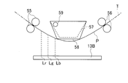
- Prior art keywords
- reading
- document
- height
- line
- image
- Prior art date
- Legal status (The legal status is an assumption and is not a legal conclusion. Google has not performed a legal analysis and makes no representation as to the accuracy of the status listed.)
- Ceased
Links
Images






Classifications
-
- H—ELECTRICITY
- H04—ELECTRIC COMMUNICATION TECHNIQUE
- H04N—PICTORIAL COMMUNICATION, e.g. TELEVISION
- H04N1/00—Scanning, transmission or reproduction of documents or the like, e.g. facsimile transmission; Details thereof
- H04N1/04—Scanning arrangements, i.e. arrangements for the displacement of active reading or reproducing elements relative to the original or reproducing medium, or vice versa
- H04N1/047—Detection, control or error compensation of scanning velocity or position
- H04N1/0473—Detection, control or error compensation of scanning velocity or position in subscanning direction, e.g. picture start or line-to-line synchronisation
-
- H—ELECTRICITY
- H04—ELECTRIC COMMUNICATION TECHNIQUE
- H04N—PICTORIAL COMMUNICATION, e.g. TELEVISION
- H04N1/00—Scanning, transmission or reproduction of documents or the like, e.g. facsimile transmission; Details thereof
- H04N1/00567—Handling of original or reproduction media, e.g. cutting, separating, stacking
- H04N1/0057—Conveying sheets before or after scanning
-
- H—ELECTRICITY
- H04—ELECTRIC COMMUNICATION TECHNIQUE
- H04N—PICTORIAL COMMUNICATION, e.g. TELEVISION
- H04N1/00—Scanning, transmission or reproduction of documents or the like, e.g. facsimile transmission; Details thereof
- H04N1/00795—Reading arrangements
- H04N1/00798—Circuits or arrangements for the control thereof, e.g. using a programmed control device or according to a measured quantity
-
- H—ELECTRICITY
- H04—ELECTRIC COMMUNICATION TECHNIQUE
- H04N—PICTORIAL COMMUNICATION, e.g. TELEVISION
- H04N1/00—Scanning, transmission or reproduction of documents or the like, e.g. facsimile transmission; Details thereof
- H04N1/024—Details of scanning heads ; Means for illuminating the original
- H04N1/028—Details of scanning heads ; Means for illuminating the original for picture information pick-up
- H04N1/03—Details of scanning heads ; Means for illuminating the original for picture information pick-up with photodetectors arranged in a substantially linear array
-
- H—ELECTRICITY
- H04—ELECTRIC COMMUNICATION TECHNIQUE
- H04N—PICTORIAL COMMUNICATION, e.g. TELEVISION
- H04N1/00—Scanning, transmission or reproduction of documents or the like, e.g. facsimile transmission; Details thereof
- H04N1/04—Scanning arrangements, i.e. arrangements for the displacement of active reading or reproducing elements relative to the original or reproducing medium, or vice versa
- H04N1/10—Scanning arrangements, i.e. arrangements for the displacement of active reading or reproducing elements relative to the original or reproducing medium, or vice versa using flat picture-bearing surfaces
- H04N1/1061—Details relating to flat picture-bearing surfaces, e.g. transparent platen
-
- H—ELECTRICITY
- H04—ELECTRIC COMMUNICATION TECHNIQUE
- H04N—PICTORIAL COMMUNICATION, e.g. TELEVISION
- H04N1/00—Scanning, transmission or reproduction of documents or the like, e.g. facsimile transmission; Details thereof
- H04N1/40—Picture signal circuits
- H04N1/401—Compensating positionally unequal response of the pick-up or reproducing head
-
- H—ELECTRICITY
- H04—ELECTRIC COMMUNICATION TECHNIQUE
- H04N—PICTORIAL COMMUNICATION, e.g. TELEVISION
- H04N2201/00—Indexing scheme relating to scanning, transmission or reproduction of documents or the like, and to details thereof
- H04N2201/0077—Types of the still picture apparatus
- H04N2201/0094—Multifunctional device, i.e. a device capable of all of reading, reproducing, copying, facsimile transception, file transception
Definitions
- the present invention relates to an image reading apparatus.
- an image reading apparatus including a plurality of line sensors that read light of different color components.
- This image reading apparatus has a platen glass and a light source for irradiating light on a document.
- a plurality of reading lines corresponding to a plurality of line sensors are set on the platen glass.
- the plurality of reading lines extend in the main scanning direction and are arranged at intervals in the sub-scanning direction.
- An imaging lens is disposed in the optical path between the platen glass and the plurality of licensors.
- the light reflected by the original passes through a plurality of reading lines on the platen glass, and then is guided to each line sensor through an imaging lens.
- Each line sensor converts the received light into an image signal and outputs it.
- a positional shift caused by chromatic aberration of the imaging lens occurs between the image signals output from each line sensor.
- a technique for correcting the image signal output from each line sensor based on a predetermined correction coefficient has been proposed.
- reading height the height from each reading line corresponding to each line sensor to the original (hereinafter referred to as reading height) is different from each other.
- a positional deviation caused by a difference in reading height occurs between image signals output from the line sensors.
- Patent Document 1 merely sets the correction coefficient independently for each of the fixed reading operation and the flow reading operation, and does not consider the curvature of the document that occurs during the flow reading operation. Therefore, it is difficult to solve the above problem simply by adopting the technique shown in Patent Document 1.
- the present invention has been made in view of the above points, and an object of the present invention is to output from each line sensor due to a difference in reading height of each line sensor at the time of document reading operation. This is to suppress the occurrence of positional deviation between the image signals to be processed.
- a plurality of reading lines which are set on the transmission portion and extend in the main scanning direction and are arranged at intervals in the sub-scanning direction, and a document pass above the reading lines.
- a document feeding device that transports the document along a predetermined transport path, a light source that irradiates the document with light, and an imaging lens that forms an image of reflected light that has been reflected by the document and passed through each reading line.
- a plurality of line sensors provided corresponding to each of the plurality of reading lines, receiving reflected light of different color components and outputting them as image signals, and between each image signal output from the plurality of line sensors And a misregistration correction unit that corrects the misregistration.
- the first correction control for correcting the positional deviation between the image signals output from the respective line sensors is executed.
- FIG. 1 is a schematic longitudinal sectional view showing a digital scanner as an image reading apparatus according to an embodiment as seen from the front side.
- FIG. 2 is an explanatory diagram for explaining the three reading lines on the platen glass and the reading height corresponding to each reading line.
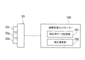
- FIG. 3 is a block diagram showing the configuration of the controller.
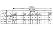
- FIG. 4A is a table showing the reference height correction data, and is data for correcting the positional deviation of red (R) with respect to green (G).
- FIG. 4B is a table showing the reference height correction data, and is data for correcting the positional deviation of blue (B) with respect to green (G).
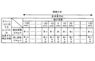
- FIG. 5A is a table showing height deviation correction data, and is data for correcting a red (R) positional deviation with respect to green (G).
- FIG. 5B is a table showing height deviation correction data, and is data for correcting a blue (B) position deviation with respect to green (G).
- FIG. 6 is a view corresponding to FIG.
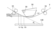
- FIG. 7 is a view corresponding to FIG.
- FIG. 8A is an explanatory diagram for explaining the rotation operation of the document conveyance angle detection member, and shows a state at the start of document conveyance.
- FIG. 8B is an explanatory diagram for explaining the rotation operation of the document conveyance angle detection member, and shows a state after the document conveyance is started. It is an IX direction arrow directional view of FIG.
- FIG. 1 shows a digital scanner 1 (hereinafter simply referred to as a scanner 1) as an image reading apparatus in the embodiment.
- the scanner 1 optically reads a document image and generates digital image data thereof.
- the scanner 1 is mounted on, for example, a copying machine or a multifunction peripheral (MFP).
- MFP multifunction peripheral
- the left side and the right side mean the left side and the right side in FIG. 1
- the front side and the rear side mean the near side and the far side in the direction perpendicular to the paper surface of FIG.
- the scanner 1 includes a housing 10, a reading unit 20, reflection mirrors 30 and 31, an imaging lens 32, a CCD sensor 33, a document feeder (ADF) 50, and a controller 100.
- ADF document feeder
- a first opening 11 and a second opening 12 are formed on the upper wall of the housing 10.
- the second opening 12 is formed at the left end of the upper wall portion of the housing 10.
- the second opening 12 has a rectangular shape that is long in the front-rear direction in plan view.
- the first opening 11 is formed on the right side of the second opening 12.
- the opening area of the first opening 11 is larger than the opening area of the second opening 12.
- the first opening 11 is closed by the first platen glass 13A.
- the first platen glass 13A is used in a fixed reading operation.
- the fixed reading operation is an operation in which the reading unit 20 reads a document placed on the first platen glass 13A.
- the second opening 12 is closed by the second platen glass 13B.
- the second platen glass 13B is used in the sink reading operation.
- the flow reading operation is an operation in which the document P is read by the reading unit 20 while the document P is conveyed by the document feeder 50.
- the first platen glass 13 ⁇ / b> A and the second platen glass 13 ⁇ / b> B are simply referred to as a platen glass 13 when it is not necessary to distinguish between them.
- the reading unit 20 includes a carriage 21, an LED light source 22, and a reflection mirror 23.
- the LED light source 22 and the reflection mirror 23 are fixed to the carriage 21 and unitized.
- the carriage 21 is configured to be movable in the sub-scanning direction (left-right direction) by a driving mechanism (not shown) using a driving motor such as a stepping motor. This drive motor is controlled by the controller 100.
- the LED light source 22 includes a large number of white LEDs arranged in the main scanning direction (front-rear direction).
- the LED light source 22 emits white light for one line in the main scanning direction toward the original P through the platen glass 13.
- the reflection mirror 23 is disposed on the diagonally lower right side of the light source 22.
- the light emitted from the LED light source 22 is reflected by the document, passes through the platen glass 13, and is guided to the reflection mirror 23.
- a line through which reflected light in the platen glass 13 passes is called a reading line.
- each platen glass 13 is provided with three reading lines, a red reading line Lr, a green reading line Lg, and a blue reading line Lb (see FIG. 2).
- Each reading line Lr, Lg, Lb corresponds to a line sensor 33r, 33g, 33b described later.
- the reading lines Lr, Lg, and Lb move in the sub scanning direction so as to follow this movement.
- the reflected light reflected by the reflection mirror 23 is sequentially reflected by the reflection mirror 30 and the reflection mirror 31 arranged on the left side of the reading unit 20, and then guided to the CCD sensor 33 through the imaging lens 32.
- the imaging lens 32 has a function of imaging the reflected light.
- the CCD sensor 33 is disposed at the imaging position of the reflected light by the imaging lens 32.
- the CCD sensor 33 includes a red line sensor 33r, a green line sensor 33g, and a blue line sensor 33b.
- Each of the line sensors 33r, 33g, and 33b is composed of a plurality of photoelectric conversion elements arranged in the main scanning direction.
- Each of the line sensors 33r, 33g, and 33b has a filter that transmits only the corresponding color component. That is, the red line sensor 33r transmits only the red component of light, the blue line sensor 33b transmits only the blue component of light, and the green line sensor 33g transmits only the green component of light.
- Each line sensor 33r, 33g, 33b outputs an image signal of a document image by photoelectrically converting light received by each photoelectric conversion element. Image signals output from the line sensors 33r, 33g, and 33b are input to the controller 100. Details of the controller 100 will be described later.
- the document feeder 50 is a device for automatically transporting the document P during the flow reading operation.
- the document feeder 50 is fixed to the document presser 60.
- the rear end edge of the document presser 60 is supported by the rear end edge of the housing 10 through a hinge member so as to be swingable.
- the document presser 60 is configured to cover the upper surface of the housing 60 so as to be openable and closable by swinging around the hinge member.
- the user opens the document holder 60, places the document P on the first platen glass 13A, and then closes the document holder 60 to fix the document P on the first platen glass 13A. Good.
- the document P may be set on the document feeder 50 with the document retainer 60 closed.
- the document feeder 50 includes a document setting unit 51, a document discharge unit 52, and a document transport unit 53.
- the document conveying portion 53 is accommodated in a rectangular parallelepiped case 58 extending in the front-rear direction.
- a paper feed port 58 a is formed on the right side surface of the case 58.
- the document setting unit 51 is composed of a tray connected to the paper feed port 58a.
- a paper discharge port 58b is formed below the paper supply port 58a on the right side surface of the case 58.
- the document discharge section 52 is provided on the right side of the discharge port 58b.
- the document discharge section 52 is formed by the upper surface of the document presser 60.
- the document conveying section 52 includes a feed roller 54, a paper feed roller pair 55, and a paper discharge roller pair 56.
- a document transport path T is formed by the feed roller 54 and the pair of rollers 55 and 56.
- the document transport path T has an arc shape that protrudes downward as viewed from the main scanning direction.
- a document guide portion 57 is disposed between the paper feed roller pair 55 and the paper discharge roller pair 56.
- the document guide portion 57 has a trapezoidal shape whose width becomes narrower toward the lower side when viewed from the main scanning direction.
- the document guide unit 57 guides the upper surface of the document P so that the document P is transported along the document transport path T.
- the reading unit 20 moves the lower side of the first platen glass 13A from the left side to the right side.
- the CCD sensor 33 generates an image signal of the entire document image.
- the reading unit 20 is stationary without moving in the left-right direction below the second platen glass 13B. Instead, the document P is transported by the document feeder 50, so that the document P moves on the second platen glass 13B. Thus, an image signal of the entire document image is generated by the CCD sensor 33. The image signal generated by the CCD sensor 33 is transmitted to the controller 100.
- the controller 100 (see FIG. 3) is constituted by a microcomputer having, for example, a CPU, a ROM, and a RAM.
- the controller 100 includes a correction data storage unit 101 and a correction calculation unit 102.
- the correction data storage unit 101 stores three types of data: chromatic aberration correction data, reference height correction data, and height deviation correction data.
- the correction calculation unit 102 corrects the positional deviation between the image signals output from the line sensors 33r, 33g, and 33b based on the correction data. In the present embodiment, the correction calculation unit 102 corrects the positional deviation of the image signals output from the red line sensor 33r and the blue line sensor 33b with reference to the image signal output from the green line sensor 33.
- the correction data will be described with reference to FIGS. 4A, 4B, 5A, and 5B.
- the chromatic aberration correction data is data for correcting a positional shift between the image signals caused by the chromatic aberration of the imaging lens 32 when the document P is placed (fixed) on the first platen glass 13A. 4 and the first stage of the correction coefficient of the correction coefficients shown in each of two stages in Fig. 5, "a -130, ... a -20, a -10, a 0, a 10, a 20 ... a 130 " , “B ⁇ 130 ,... B ⁇ 20 , b ⁇ 10 , b 0 , b 10 , b 20 ... B 130 ” is chromatic aberration correction data.
- This a means a red misregistration correction coefficient for green
- b means a blue misregistration correction coefficient for green
- the subscript means a position in the sub-scanning direction. Since the chromatic aberration of the imaging lens 32 is generally larger toward the outer side in the sub-scanning direction, the correction coefficient is also set to be larger toward the outer side in the sub-scanning direction. It means that the larger the correction coefficient, the larger the correction amount of the positional deviation.
- the reference height correction data corrects misalignment between image signals caused by an increase in the document reading height of the green line sensor 33g, which is a correction reference, in the flow reading operation and in the fixed reading operation. It is data to do.
- the reading height is a vertical distance from the reading lines Lr, Lg, and Lb to the conveyance path T.
- correction is performed based on the reading height hg of the green line sensor 33g, which is a correction reference.
- the red misregistration correction coefficient for green is set to a value obtained by multiplying the correction coefficient a of the chromatic aberration correction data by A (see FIG. 4A).
- This A is set so as to increase as the reading height hg of the green line sensor 33g serving as a correction reference increases.
- the blue misregistration correction coefficient for green is set to a value obtained by multiplying the correction coefficient a of the chromatic aberration correction data by B (see FIG. 4B).
- This B is set so as to increase as the reading height hg of the green line sensor 33g serving as a correction reference increases.
- the height deviation correction data is derived from the fact that the reading heights of the blue line sensor 33b and the red line sensor 33r are different from the reading height hg of the green sensor 33g serving as a correction reference during the flow reading operation. This is data for correcting misalignment between image signals.
- ⁇ Hrg represents a difference in reading height between the red line sensor 33g and the green line sensor 33g
- ⁇ Hbg represents a difference in reading height between the blue line sensor 33b and the green line sensor 33g.
- the red position deviation correction coefficient for green is set to a value obtained by multiplying the correction coefficient a of the chromatic aberration correction data by ⁇ (see FIG. 5A).
- This ⁇ is set so as to increase as the height deviation ⁇ Hrg increases.
- the blue position deviation correction coefficient for green is set to a value obtained by multiplying the correction coefficient b of the chromatic aberration correction data by ⁇ (see FIG. 5B).
- This ⁇ is set so as to increase as the height deviation ⁇ Hbg increases.
- the red misregistration correction coefficient for green is a ⁇ A ⁇ ⁇
- the blue misregistration correction coefficient for green is b ⁇ B ⁇ ⁇ .
- the controller 100 corrects the positional deviation between the image signals based on the height shift correction data.
- the controller 100 outputs images output from the line sensors 33r, 33g, and 33b based on the difference in reading height ( ⁇ Hrg, ⁇ Hbg) of the line sensors 33r, 33g, and 33b that occurs during the flow reading operation of the document P.
- Control for correcting the positional deviation between the signals (hereinafter referred to as first correction control) is executed.
- first correction control is executed.
- the position shift between each image signal can be suppressed reliably.
- the image quality of the original image obtained by the flow reading operation can be improved.
- FIG. 6 shows a second embodiment.
- the present embodiment is different from the first embodiment in that the controller 100 further includes a foreign object avoidance control unit 103, a reference reading height calculation unit 104, and a height deviation calculation unit 105.
- the same control components as those in FIG. 3 are denoted by the same reference numerals, and detailed description thereof is omitted.
- the foreign matter avoidance control unit 103 first starts the foreign matter on at least one of the three reading lines Lr, Lg, and Lb before starting the reading operation. It is determined whether or not. This determination is made based on, for example, whether or not there is a portion where the luminance value is below the threshold in the image signals output from the line sensors 33r, 33g, and 33b.
- the foreign matter avoidance control unit 103 determines that a foreign matter is placed, the foreign matter avoidance control unit 103 moves the reading unit 20 by a predetermined amount in the sub-scanning direction. The foreign matter avoidance control unit 103 repeats this avoidance operation until no foreign matter is present on the reading lines Lr, Lg, and Lb.
- the reading height hg and the height deviations ⁇ Hrg and ⁇ Hbg also change depending on the position of the reading unit 20 in the sub-scanning direction.
- the reference reading height calculation unit 104 calculates the reading height hg based on the previously stored shape and position of the transport path T and the position of the green reading line Lg that is the reference line in the sub-scanning direction. To do.
- the position of the green reading line Lg in the sub-scanning direction may be detected based on the rotation angle of the drive motor that drives the reading unit 20.
- the height deviation calculation unit 105 determines the height deviations ⁇ Hrg and ⁇ Hbg based on the shape and position of the transport path T stored in advance and the positions of the reading lines Lr, Lg, and Lb in the sub-scanning direction.
- the positions of the read lines Lr, Lg, and Lb calculated in the above are based on the rotation angle of the drive motor that drives the read unit 20 and the distance between the optical axes of the line sensors 33r, 33g, and 33b. What is necessary is just to calculate (detect).
- the correction calculation unit 102 increases the magnification A and the magnification B to be applied to the correction coefficient a and the correction coefficient b as the reading height hg calculated by the reference reading height calculation unit 104 is larger, thereby causing a positional deviation between the image signals. Correct.
- the correction calculation unit 102 increases the magnification ⁇ and the magnification ⁇ to be applied to the correction coefficient a and the correction coefficient b as the height deviations ⁇ Hrg and ⁇ Hbg calculated by the height deviation calculation unit 105 are larger. Correct the deviation.
- the controller 100 executes the first correction control as in the first embodiment. Therefore, it is possible to obtain the same effect as that of the first embodiment.
- the controller 100 outputs from each line sensor 33r, 33g, 33b based on the read height hg calculated by the reference read height calculation unit 104 in addition to the first correction control. Further, a control (second correction control) for correcting the positional deviation between the image signals to be performed is executed. Accordingly, not only the difference ⁇ Hrg and ⁇ Hbg between the reading heights of the line sensors 33r, 33g and 33b but also the change in the reading height of the reference green line sensor 33g is taken into account to correct the positional deviation of each image signal. can do.
- the foreign object avoidance control unit 103 of the controller 100 executes the foreign object avoidance control, so that black streaks can be prevented from occurring in the read image. Even if the reading line is moved due to the execution of the foreign matter avoidance control, the reference reading height calculation unit 104 automatically calculates the reading height hg of the green line sensor 33g as a reference, and the height deviation calculation unit 105 The height differences ⁇ Hrg and Hbg are automatically calculated, and the correction calculation unit 102 automatically calculates the height deviation of each of the line sensors 33r, 33g, and 33b based on these calculated values.
- the transport path T of the document P by the document feeder 50 has an arc shape that protrudes downward as viewed from the main scanning direction.
- the positional deviation correction by the correction calculation unit 102 is particularly useful.
- FIG. 7 shows a third embodiment.
- the third embodiment is different from the first embodiment in that the document guide portion 57 can be rotated around the shaft 59.
- symbol is attached
- document conveyance angle detection members 58 are provided on both sides in the main scanning direction of the document guide portion (corresponding to the document restriction portion) 57 (see FIGS. 8A, 8B, and 9). Both document conveyance angle detection members 58 have a trapezoidal plate shape.
- the document conveyance angle detection member 58 is supported to be swingable with respect to the document guide portion 57 via a shaft 59.
- the shaft 59 is fixed to the case 58.
- the shaft 59 passes through the document guide portion 57 in the main scanning direction.
- the document conveyance angle detection member 58 is fixed to both ends of the shaft 59.
- the rotation angle of the document conveyance angle detection member 58 is detected by a rotation angle detection sensor 70.
- the rotation angle detection sensor 70 is connected to the controller 100.
- the rotation angle detection sensor 70 is composed of, for example, a transmissive photo interrupter having a light receiving element and a light emitting element.
- the document conveyance angle detection member 58 has a plurality of slit holes (not shown) for angle detection by a photo interrupter.
- the rotation angle detection sensor 70 detects the rotation angle of the document conveyance angle detection member 58 and transmits the detected rotation angle information to the controller 100.
- the rotation angle detection sensor 70 may be, for example, a reflective photo interrupter. In this case, a plurality of slit grooves may be provided instead of the slit holes of the document conveyance angle detection member 58.
- the document transport angle detection member 58 contacts the upper surface of the document P and guides the document P (see FIG. 8A). After the conveyance of the original P is started by the original feeder 50, the original P is gradually stretched by increasing the tension acting on the original P (see FIG. 8B). When the document P is stretched, the document transport angle detection member 58 is pushed upward by the document P and rotates around the shaft 59. The rotation angle of the document conveyance angle detection member 58 is detected by the rotation angle detection sensor 70 and transmitted to the controller 100.
- the controller 100 includes a correction data storage unit 101 and a correction calculation unit 102 as in the first embodiment.
- the correction data storage unit 101 stores three types of data: chromatic aberration correction data, reference height correction data, and height deviation correction data. Since the contents of these correction data are the same as those in the first embodiment, description thereof is omitted.
- the correction calculation unit 102 corrects the positional deviation between the image signals output from the line sensors 33r, 33g, and 33b based on the correction data.
- the correction calculation unit 102 corrects the positional deviation of the image signals output from the red line sensor 33r and the blue line sensor 33b with reference to the image signal output from the green line sensor 33.
- the correction calculation unit 102 first determines the document conveyance angle ⁇ (see FIG. 5), which is the inclination angle of the document P with respect to the platen glass 13B, based on the rotation angle of the conveyance angle detection member 58 received from the rotation angle detection sensor 70. 8B) is calculated. This calculation is performed using table data (not shown) stored in advance in the ROM.
- This table data is data that summarizes the relationship between the rotation angle of the conveyance angle detection member 58 and the document conveyance angle ⁇ , and is obtained by performing a conveyance test, for example.
- the correction calculation unit 102 calculates the calculated document conveyance angle ⁇ and the position of each reading line Lr, Lg, Lb on the platen glass 13B corresponding to each line sensor 33r, 33g, 33b stored in advance in the ROM. Based on the information, the height difference from the reading lines Lr, Lg, Lb to the original P is calculated. Specifically, the correction calculation unit 102 determines the difference ⁇ Hrg between the height hg from the reference green reading line Lg to the document P and the height hr from the red reading line Lr to the document P, and the reference height. A difference ⁇ Hbg between hg and the height hb from the blue reading line Lb to the original P is calculated. The correction calculator 102 corrects the positional deviation between the image signals output from the line sensors 33r, 33g, and 33b based on the height differences ⁇ Hrg and ⁇ Hbg.
- each line sensor is based on the difference ( ⁇ Hrg, ⁇ Hbg) between the reading heights of the line sensors 33r, 33g, 33b generated by the controller 1 during the flow reading operation of the document P.
- the positional deviation between the image signals output from 33r, 33g, and 33b is corrected. Therefore, it is possible to reliably suppress the positional deviation between the image signals. As a result, the image quality of the original image obtained by the flow reading operation can be improved. In addition, it is possible to suppress a difference in image quality of the read image between the fixed reading operation and the flow reading operation.
- the controller 100 calculates the conveyance angle ⁇ of the document P based on the rotation angle of the document conveyance angle detection member 58 and stores the calculated conveyance angle ⁇ of the document P in the ROM in advance. Based on the positions of the reading lines Lr, Lg, and Lb, the height differences ⁇ Hrg and ⁇ Hbg from the reading lines Lr, Lg, and Lb to the original P are calculated.
- the controller 100 can accurately calculate the height difference. As a result, the correction accuracy of the positional deviation between the image signals by the controller 100 can be improved.
- line sensors that is, in each of the embodiments described above, three examples of line sensors have been described.
- the number of line sensors is not limited to this, and may be two, for example, or three or more.
- the positional deviation correction of the red and blue image signals is performed based on the green image signal.
- the present invention is not limited to this.
- the blue image signal may be used as a reference.
- a red image signal may be used as a reference.
- the present invention includes any combination of the above embodiments.
- the present invention is useful for an image reading apparatus, and particularly useful for an image reading apparatus provided with a document feeder.
Landscapes
- Engineering & Computer Science (AREA)
- Multimedia (AREA)
- Signal Processing (AREA)
- Facsimile Scanning Arrangements (AREA)
- Image Input (AREA)
- Facsimile Image Signal Circuits (AREA)
Abstract
Description
図1は、実施形態における画像読取装置としてのデジタルスキャナー1(以下、単にスキャナー1という)を示している。このスキャナー1は、原稿画像を光学的に読み取ってそのデジタル画像データを生成する。スキャナー1は、例えば複写機や複合機(MFP)に搭載される。尚、以下の説明において、左側、右側は、図1の左側、右側を意味し、前側、後側は、図1の紙面に垂直方向の手前側、奥側を意味する。
図6は、実施形態2を示している。本実施形態は、コントローラー100が異物回避制御部103、基準読取り高さ算出部104,高さずれ算出部105をさらに有する点で上記実施形態1とは異なる。図3と同じ制御構成部には同じ符号を付して、その詳細な説明を省略する。
図7は、実施形態3を示している。この実施形態3は、原稿ガイド部57がシャフト59回りに回動可能である点で上記実施形態1とは異なる。尚、上記実施形態1と同じ構成要素には同じ符号を付してその詳細な説明を省略する。
本発明は、上記各実施形態について、以下のような構成としてもよい。
Claims (8)
- 透過部上に設定され、主走査方向に延びると共に副走査方向に間隔を空けて並ぶ複数の読取ラインと、該複数の読取ラインの上側を原稿が通過するように該原稿を所定の搬送経路に沿って搬送する原稿送り装置と、上記原稿に光を照射する光源と、該原稿で反射して各読取ラインを通過した反射光を結像させる結像レンズと、上記複数の読取ラインのそれぞれに対応して設けられ、互いに異なる色成分の反射光を受光して画像信号として出力する複数のラインセンサーと、該複数のラインセンサーから出力される各画像信号間の位置ずれを補正する位置ずれ補正部と、を備えた画像読取装置であって、
上記位置ずれ補正部は、上記各ラインセンサーに対応する透過部上の各読取ラインから上記所定の搬送経路までの高さを該各ラインセンサーの読取り高さとしたとき、該各ラインセンサーの読取り高さの差に基づいて、該各ラインセンサーから出力される画像信号間の位置ずれを補正する第一補正制御を実行するように構成されている、画像読取装置。 - 請求項1記載の画像読取装置において、
上記複数の読取ラインを副走査方向に移動させるための読取ライン移動部と、
上記複数の読取ラインの副走査方向の位置と、上記搬送経路の形状及び位置とに基づいて、上記各ラインセンサーの読取り高さの差を算出する高さずれ算出部とを備え、
上記位置ずれ補正部による第一補正制御は、上記高さずれ算出部により算出された各ラインセンサーの読取り高さの差に基づいて、該各ラインセンサーから出力される画像信号間の位置ずれを補正する制御である、画像読取装置。 - 請求項2記載の画像読取装置において、
上記複数の読取ラインのうち少なくとも一つのライン上に異物が載っているか否かを判定して、異物が載っていると判定した場合に、読取ライン移動部によって読取ラインを副走査方向に移動させることで、読取ライン上に異物が載るのを回避する異物回避制御を実行する異物回避制御部を備えている、画像読取装置。 - 請求項1記載の画像読取装置において、
上記搬送経路は、主走査方向から見て下側に凸となる円弧状をなしている、画像読取装置。 - 請求項1記載の画像読取装置において、
上記複数の読取ラインのうち予め設定した一の基準読取ラインの副走査方向の位置を検出する位置検出部と、
上記位置検出部により検出された上記基準読取ラインの位置と、上記所定の搬送経路の形状及び位置とを基に、上記基準読取ラインに対応するラインセンサーの読取り高さを算出する基準読取り高さ算出部と、を備え、
上記位置ずれ補正部は、上記第1補正制御に加えて、上記基準読取り高さ算出部により算出された上記読取り高さに基づいて上記各ラインセンサーから出力される画像信号間の位置ずれを補正する第二補正制御をさらに実行するように構成されている、画像読取装置。 - 請求項5記載の画像読取装置において、
上記搬送経路は、主走査方向から見て下側に凸となる円弧状をなしている、画像読取装置。 - 請求項1記載の画像読取装置において、
上記原稿送り装置により上記原稿の搬送を開始する時に当該原稿の上面に当接するように設けられた原稿搬送角度検知部材と、
上記主走査方向に延びるとともに上記原稿搬送角度検知部材を揺動可能に支持する支持シャフトと、
上記原稿搬送角度検知部材の上記支持シャフト回りの回転角度を検出するための角度検出センサーと、を備え、
上記原稿搬送角度検知部材は、上記原稿送り装置により上記原稿の搬送が開始されると、上記原稿により上側に押圧されることにより上記支持シャフト回りに上側に回動するように構成されており、
上記位置ずれ補正部による第一補正制御は、上記原稿搬送角度検知部材の回転角度を基に上記原稿の搬送角度を算出すると共に、該算出した原稿の搬送角度と、上記各ラインセンサーに対応する透過部上の各読取ラインの位置とを基に、該各ラインセンサーの読取り高さの差を算出して、該算出した読取り高さの差に基づいて、該各ラインセンサーから出力される画像信号間の位置ずれを補正する制御である、画像読取装置。 - 請求項7記載の画像読取装置において、
上記原稿送り装置による上記原稿の搬送経路は、主走査方向から見て下側に凸となる円弧状をなしている、画像読取装置。
Priority Applications (4)
| Application Number | Priority Date | Filing Date | Title |
|---|---|---|---|
| US15/107,703 US9900459B2 (en) | 2014-01-31 | 2015-01-19 | Image reading device |
| EP15743484.6A EP3101886B1 (en) | 2014-01-31 | 2015-01-19 | Image read-in device |
| JP2015559871A JP6217946B2 (ja) | 2014-01-31 | 2015-01-19 | 画像読取装置 |
| CN201580003193.9A CN105814871B (zh) | 2014-01-31 | 2015-01-19 | 图像读取装置 |
Applications Claiming Priority (6)
| Application Number | Priority Date | Filing Date | Title |
|---|---|---|---|
| JP2014-018059 | 2014-01-31 | ||
| JP2014-018053 | 2014-01-31 | ||
| JP2014-018043 | 2014-01-31 | ||
| JP2014018053 | 2014-01-31 | ||
| JP2014018059 | 2014-01-31 | ||
| JP2014018043 | 2014-01-31 |
Publications (1)
| Publication Number | Publication Date |
|---|---|
| WO2015115216A1 true WO2015115216A1 (ja) | 2015-08-06 |
Family
ID=53756793
Family Applications (1)
| Application Number | Title | Priority Date | Filing Date |
|---|---|---|---|
| PCT/JP2015/051165 Ceased WO2015115216A1 (ja) | 2014-01-31 | 2015-01-19 | 画像読取装置 |
Country Status (5)
| Country | Link |
|---|---|
| US (1) | US9900459B2 (ja) |
| EP (1) | EP3101886B1 (ja) |
| JP (1) | JP6217946B2 (ja) |
| CN (1) | CN105814871B (ja) |
| WO (1) | WO2015115216A1 (ja) |
Families Citing this family (2)
| Publication number | Priority date | Publication date | Assignee | Title |
|---|---|---|---|---|
| JP2018207437A (ja) * | 2017-06-09 | 2018-12-27 | セイコーエプソン株式会社 | スキャナー、スキャンデータの生産方法 |
| KR20240027200A (ko) * | 2022-08-22 | 2024-03-04 | 삼성디스플레이 주식회사 | 결함 검사 장치 및 결함 검사 방법 |
Citations (4)
| Publication number | Priority date | Publication date | Assignee | Title |
|---|---|---|---|---|
| JP2004343190A (ja) * | 2003-05-13 | 2004-12-02 | Ricoh Co Ltd | 画像読取装置 |
| JP2006033386A (ja) | 2004-07-15 | 2006-02-02 | Canon Inc | 画像読み取り装置 |
| JP2008048043A (ja) * | 2006-08-11 | 2008-02-28 | Konica Minolta Business Technologies Inc | シートスルー方式の原稿読取装置 |
| JP2013005190A (ja) * | 2011-06-15 | 2013-01-07 | Pfu Ltd | 画像読取装置、画像処理方法、および、プログラム |
Family Cites Families (8)
| Publication number | Priority date | Publication date | Assignee | Title |
|---|---|---|---|---|
| US20040169895A1 (en) * | 2003-02-28 | 2004-09-02 | Kabushiki Kaisha Toshiba | Image reading apparatus |
| JP2004266543A (ja) * | 2003-02-28 | 2004-09-24 | Toshiba Tec Corp | 画像読取装置および画像読取方法 |
| JP4513383B2 (ja) * | 2003-04-02 | 2010-07-28 | 株式会社カネカ | 新規パン酵母 |
| JP2007104124A (ja) * | 2005-09-30 | 2007-04-19 | Kyocera Mita Corp | 画像読取装置 |
| JP4840079B2 (ja) * | 2006-10-27 | 2011-12-21 | 富士ゼロックス株式会社 | 読み取り装置及び複写機 |
| JP5308680B2 (ja) | 2008-01-23 | 2013-10-09 | 京セラドキュメントソリューションズ株式会社 | 画像読取装置、及びこれを備えた画像形成装置 |
| JP2010135970A (ja) * | 2008-12-03 | 2010-06-17 | Murata Machinery Ltd | 画像読取装置及びそのキャリブレーション方法 |
| JP5584490B2 (ja) * | 2010-02-18 | 2014-09-03 | キヤノン株式会社 | 画像処理装置、画像処理方法およびプログラム |
-
2015
- 2015-01-19 CN CN201580003193.9A patent/CN105814871B/zh not_active Expired - Fee Related
- 2015-01-19 JP JP2015559871A patent/JP6217946B2/ja not_active Expired - Fee Related
- 2015-01-19 US US15/107,703 patent/US9900459B2/en not_active Expired - Fee Related
- 2015-01-19 WO PCT/JP2015/051165 patent/WO2015115216A1/ja not_active Ceased
- 2015-01-19 EP EP15743484.6A patent/EP3101886B1/en active Active
Patent Citations (4)
| Publication number | Priority date | Publication date | Assignee | Title |
|---|---|---|---|---|
| JP2004343190A (ja) * | 2003-05-13 | 2004-12-02 | Ricoh Co Ltd | 画像読取装置 |
| JP2006033386A (ja) | 2004-07-15 | 2006-02-02 | Canon Inc | 画像読み取り装置 |
| JP2008048043A (ja) * | 2006-08-11 | 2008-02-28 | Konica Minolta Business Technologies Inc | シートスルー方式の原稿読取装置 |
| JP2013005190A (ja) * | 2011-06-15 | 2013-01-07 | Pfu Ltd | 画像読取装置、画像処理方法、および、プログラム |
Also Published As
| Publication number | Publication date |
|---|---|
| US20160323475A1 (en) | 2016-11-03 |
| CN105814871B (zh) | 2018-09-18 |
| CN105814871A (zh) | 2016-07-27 |
| EP3101886B1 (en) | 2019-05-08 |
| EP3101886A4 (en) | 2017-07-05 |
| JPWO2015115216A1 (ja) | 2017-03-23 |
| US9900459B2 (en) | 2018-02-20 |
| JP6217946B2 (ja) | 2017-10-25 |
| EP3101886A1 (en) | 2016-12-07 |
Similar Documents
| Publication | Publication Date | Title |
|---|---|---|
| US9055175B2 (en) | Image reading apparatus, and image forming apparatus | |
| US8760727B2 (en) | Sheet-conveying device having opening | |
| JP5198485B2 (ja) | 画像読取装置、白基準チャート、シェーディング補正方法、画像形成装置 | |
| JP4539424B2 (ja) | 画像読取装置 | |
| JP6217946B2 (ja) | 画像読取装置 | |
| JP6047528B2 (ja) | 画像読取装置及び画像形成装置 | |
| JP2019105710A (ja) | 画像形成装置 | |
| JP4163537B2 (ja) | 画像読取装置 | |
| JP5742476B2 (ja) | 画像読取装置および読取画像データの補正方法 | |
| JP2002354207A (ja) | 画像読取装置 | |
| JP5206582B2 (ja) | 画像読取装置 | |
| JP5298928B2 (ja) | 画像読取装置、画像形成装置及び画像読取方法 | |
| JP2023003470A (ja) | 画像読取装置、画像処理方法及びプログラム | |
| JP6344062B2 (ja) | 画像読取装置、画像形成装置、画像処理方法 | |
| JP2014030143A (ja) | 読取装置、その読取装置における補正方法およびプログラム | |
| JP2011259430A (ja) | 画像読取装置及び画像読取異常検出方法 | |
| JP4528319B2 (ja) | 原稿読取装置 | |
| JP5874269B2 (ja) | 画像読み取り装置およびプログラム | |
| JP5999327B2 (ja) | 画像読取装置並びに画像形成装置 | |
| JP2025096064A (ja) | 読取装置、画像処理装置、読取方法およびプログラム | |
| JP2010245688A (ja) | 原稿読取装置 | |
| JP5129215B2 (ja) | 画像形成装置 | |
| JP2009159215A (ja) | 画像読み取り装置 | |
| JP2020156055A (ja) | 画像処理装置、白紙原稿判定方法 | |
| JP2021077949A (ja) | 画像読取装置 |
Legal Events
| Date | Code | Title | Description |
|---|---|---|---|
| 121 | Ep: the epo has been informed by wipo that ep was designated in this application |
Ref document number: 15743484 Country of ref document: EP Kind code of ref document: A1 |
|
| ENP | Entry into the national phase |
Ref document number: 2015559871 Country of ref document: JP Kind code of ref document: A |
|
| REEP | Request for entry into the european phase |
Ref document number: 2015743484 Country of ref document: EP |
|
| WWE | Wipo information: entry into national phase |
Ref document number: 2015743484 Country of ref document: EP |
|
| WWE | Wipo information: entry into national phase |
Ref document number: 15107703 Country of ref document: US |
|
| NENP | Non-entry into the national phase |
Ref country code: DE |