WO2015115251A1 - 空気調和装置 - Google Patents
空気調和装置 Download PDFInfo
- Publication number
- WO2015115251A1 WO2015115251A1 PCT/JP2015/051405 JP2015051405W WO2015115251A1 WO 2015115251 A1 WO2015115251 A1 WO 2015115251A1 JP 2015051405 W JP2015051405 W JP 2015051405W WO 2015115251 A1 WO2015115251 A1 WO 2015115251A1
- Authority
- WO
- WIPO (PCT)
- Prior art keywords
- indoor
- air volume
- air
- temperature
- fans
- Prior art date
- Legal status (The legal status is an assumption and is not a legal conclusion. Google has not performed a legal analysis and makes no representation as to the accuracy of the status listed.)
- Ceased
Links
Images


Classifications
-
- F—MECHANICAL ENGINEERING; LIGHTING; HEATING; WEAPONS; BLASTING
- F24—HEATING; RANGES; VENTILATING
- F24F—AIR-CONDITIONING; AIR-HUMIDIFICATION; VENTILATION; USE OF AIR CURRENTS FOR SCREENING
- F24F11/00—Control or safety arrangements
- F24F11/70—Control systems characterised by their outputs; Constructional details thereof
- F24F11/72—Control systems characterised by their outputs; Constructional details thereof for controlling the supply of treated air, e.g. its pressure
- F24F11/74—Control systems characterised by their outputs; Constructional details thereof for controlling the supply of treated air, e.g. its pressure for controlling air flow rate or air velocity
- F24F11/77—Control systems characterised by their outputs; Constructional details thereof for controlling the supply of treated air, e.g. its pressure for controlling air flow rate or air velocity by controlling the speed of ventilators
-
- F—MECHANICAL ENGINEERING; LIGHTING; HEATING; WEAPONS; BLASTING
- F24—HEATING; RANGES; VENTILATING
- F24F—AIR-CONDITIONING; AIR-HUMIDIFICATION; VENTILATION; USE OF AIR CURRENTS FOR SCREENING
- F24F1/00—Room units for air-conditioning, e.g. separate or self-contained units or units receiving primary air from a central station
- F24F1/0003—Room units for air-conditioning, e.g. separate or self-contained units or units receiving primary air from a central station characterised by a split arrangement, wherein parts of the air-conditioning system, e.g. evaporator and condenser, are in separately located units
-
- F—MECHANICAL ENGINEERING; LIGHTING; HEATING; WEAPONS; BLASTING
- F24—HEATING; RANGES; VENTILATING
- F24F—AIR-CONDITIONING; AIR-HUMIDIFICATION; VENTILATION; USE OF AIR CURRENTS FOR SCREENING
- F24F11/00—Control or safety arrangements
- F24F11/70—Control systems characterised by their outputs; Constructional details thereof
- F24F11/72—Control systems characterised by their outputs; Constructional details thereof for controlling the supply of treated air, e.g. its pressure
- F24F11/74—Control systems characterised by their outputs; Constructional details thereof for controlling the supply of treated air, e.g. its pressure for controlling air flow rate or air velocity
- F24F11/76—Control systems characterised by their outputs; Constructional details thereof for controlling the supply of treated air, e.g. its pressure for controlling air flow rate or air velocity by means responsive to temperature, e.g. bimetal springs
-
- F—MECHANICAL ENGINEERING; LIGHTING; HEATING; WEAPONS; BLASTING
- F24—HEATING; RANGES; VENTILATING
- F24F—AIR-CONDITIONING; AIR-HUMIDIFICATION; VENTILATION; USE OF AIR CURRENTS FOR SCREENING
- F24F11/00—Control or safety arrangements
- F24F11/30—Control or safety arrangements for purposes related to the operation of the system, e.g. for safety or monitoring
- F24F11/46—Improving electric energy efficiency or saving
-
- F—MECHANICAL ENGINEERING; LIGHTING; HEATING; WEAPONS; BLASTING
- F24—HEATING; RANGES; VENTILATING
- F24F—AIR-CONDITIONING; AIR-HUMIDIFICATION; VENTILATION; USE OF AIR CURRENTS FOR SCREENING
- F24F2110/00—Control inputs relating to air properties
- F24F2110/10—Temperature
- F24F2110/12—Temperature of the outside air
-
- Y—GENERAL TAGGING OF NEW TECHNOLOGICAL DEVELOPMENTS; GENERAL TAGGING OF CROSS-SECTIONAL TECHNOLOGIES SPANNING OVER SEVERAL SECTIONS OF THE IPC; TECHNICAL SUBJECTS COVERED BY FORMER USPC CROSS-REFERENCE ART COLLECTIONS [XRACs] AND DIGESTS
- Y02—TECHNOLOGIES OR APPLICATIONS FOR MITIGATION OR ADAPTATION AGAINST CLIMATE CHANGE
- Y02B—CLIMATE CHANGE MITIGATION TECHNOLOGIES RELATED TO BUILDINGS, e.g. HOUSING, HOUSE APPLIANCES OR RELATED END-USER APPLICATIONS
- Y02B30/00—Energy efficient heating, ventilation or air conditioning [HVAC]
- Y02B30/70—Efficient control or regulation technologies, e.g. for control of refrigerant flow, motor or heating
Definitions
- the present invention relates to an air conditioner, and more particularly to an air conditioner capable of manually instructing the air volume setting of an indoor fan.
- An object of the present invention is to reduce wasteful power consumption of an indoor fan and improve APF in an air conditioner capable of manually instructing the air volume setting of the indoor fan.
- the air conditioner according to the first aspect includes an outdoor unit and an indoor unit having an indoor heat exchanger and an indoor fan, and is an air conditioner capable of manually instructing the air volume setting of the indoor fan.
- indoor air volume restriction control is performed to forcibly limit the air volume setting of the indoor fan to the low air volume side according to the outside air temperature in a state where the air volume setting of the indoor fan is manually instructed.
- the indoor air volume restriction control is performed in the state where the indoor fan air volume setting is manually instructed, so that when the indoor fan air volume is unnecessarily large when viewed from the outside air temperature, The fan air volume can be forcibly reduced.
- An air conditioner according to a second aspect is the air conditioner according to the first aspect, wherein the outdoor unit or the indoor unit has an indoor flow rate adjustment valve that adjusts the flow rate of the refrigerant flowing through the indoor heat exchanger.
- the opening of the indoor flow rate control valve is equal to or less than the air volume restriction permission opening, the indoor air volume restriction control is performed.
- the indoor air conditioning load is large, restricting the indoor fan air volume setting to the low air volume side will process the indoor air conditioning load even if the air volume of the indoor fan is large when viewed from the outside air temperature. In this case, it is not preferable to perform the indoor air volume restriction control.
- the indoor air conditioning load is large, the flow rate of the refrigerant flowing through the indoor heat exchanger tends to increase.
- whether or not the indoor air conditioning load is large is determined based on the opening of the indoor flow rate control valve that increases as the flow rate of the refrigerant flowing through the indoor heat exchanger increases. ing.
- the indoor air volume restriction control can be appropriately performed in consideration of not only the outside air temperature but also the indoor air conditioning load.
- An air conditioner according to a third aspect is the air conditioner according to the first or second aspect, wherein an upper air volume upper limit of the indoor fan that can be changed according to the outside air temperature is provided, and the upper air volume upper limit of the indoor fan is reduced. To control indoor air volume restriction.
- the air conditioner according to the fourth aspect is the air conditioner according to the third aspect, wherein the air volume upper limit of the indoor fan is decreased according to the decrease in the outside air temperature during the cooling operation and / or during the heating operation.
- the upper limit of the air volume of the indoor fan is lowered according to the increase in the outside air temperature.
- the indoor air volume restriction control is performed by setting the upper air volume limit of the indoor fan
- the air volume setting of the indoor fan that is manually instructed is higher than the upper air volume limit.
- the air volume setting of the indoor fan can be forcibly reduced to the air volume upper limit.
- the air volume setting of the indoor fan instructed manually is an air volume below the upper limit of the air volume
- the air volume setting of the indoor fan can be maintained with the air volume setting of the indoor fan instructed manually.
- the indoor air volume restriction control can be performed while maintaining the manually instructed indoor fan air volume setting as much as possible.
- the air volume setting of the indoor fan is set to the low air volume side. Relax restrictions.
- the indoor air volume restriction control When the indoor air volume restriction control is performed, if the operating condition changes such as an increase in the air conditioning load in the room, the indoor temperature may deviate from the target indoor temperature. It is not preferable to keep it excessively restricted to the low air volume side.
- the indoor air volume restriction control can be appropriately performed here in consideration of not only the outside air temperature but also the indoor temperature change.
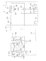
- FIG. 1 is a schematic configuration diagram of an air conditioner 1 according to an embodiment of the present invention.
- the air conditioning apparatus 1 is an apparatus used for air conditioning indoors such as buildings by performing a vapor compression refrigeration cycle operation.
- the air conditioner 1 is mainly configured by connecting an outdoor unit 2 and a plurality (here, two) of indoor units 4 and 5.
- the outdoor unit 2 and the plurality of indoor units 4 and 5 are connected via a liquid refrigerant communication tube 6 and a gas refrigerant communication tube 7.
- the vapor compression refrigerant circuit 10 of the air conditioner 1 is configured by connecting the outdoor unit 2 and the plurality of indoor units 4 and 5 via the refrigerant communication pipes 6 and 7.
- the indoor units 4 and 5 are installed indoors.
- the indoor units 4 and 5 are connected to the outdoor unit 2 through the refrigerant communication pipes 6 and 7 and constitute a part of the refrigerant circuit 10.
- the configuration of the indoor units 4 and 5 will be described. Since the indoor unit 5 has the same configuration as that of the indoor unit 4, only the configuration of the indoor unit 4 will be described here.
- the configuration of the indoor unit 5 is indicated by reference numerals indicating the respective parts of the indoor unit 4. The description will be omitted by replacing the number base with the number 50.
- the indoor unit 4 mainly has an indoor refrigerant circuit 10a (in the indoor unit 5, the indoor refrigerant circuit 10b) that constitutes a part of the refrigerant circuit 10.
- the indoor refrigerant circuit 10a mainly includes an indoor expansion valve 41 and an indoor heat exchanger 42.
- the indoor expansion valve 41 is an indoor flow rate adjusting valve that adjusts the flow rate of the refrigerant by reducing the pressure of the refrigerant flowing through the indoor refrigerant circuit 10a.
- the indoor expansion valve 41 is an electric expansion valve connected to the liquid side of the indoor heat exchanger 42.
- the indoor heat exchanger 42 includes, for example, a cross fin type fin-and-tube heat exchanger.
- An indoor fan 43 for sending indoor air to the indoor heat exchanger 42 is provided in the vicinity of the indoor heat exchanger 42. By blowing indoor air to the indoor heat exchanger 42 by the indoor fan 43, the indoor heat exchanger 42 performs heat exchange between the refrigerant and the indoor air.
- the indoor fan 43 is rotationally driven by an indoor fan motor 43a. Accordingly, the indoor heat exchanger 42 functions as a refrigerant radiator or a refrigerant evaporator.
- the indoor fan motor 43a can vary the air volume of the indoor fan 43 by changing the number of rotations.
- the air volume of the indoor fan 43 is changed by changing the rotation speed of the indoor fan motor 43a, so that the air volume H having the largest rotation speed and the large air volume H, the air volume M having a medium air volume smaller than the rotation speed of the air volume H, It can be changed in four stages between an air volume L of a small air volume that is much smaller than the rotational speed of the air volume M, and an air volume LL of a minimum air volume that is smaller than the rotational speed of the air volume L.
- the three air volume settings of the air volume H, the air volume M, and the air volume L can be manually instructed from the remote controller 48, but the air volume LL cannot be instructed manually from the remote controller 48.
- the air volume setting of the indoor fan 43 is switched in four stages of the air volume H, the air volume M, and the air volume L including the air volume LL, but may be 5 or more stages.
- the indoor unit 4 is provided with various sensors. On the liquid side of the indoor heat exchanger 42, a liquid side temperature sensor 44 that detects the temperature Trla (Trlb in the outdoor unit 5) of the refrigerant in the liquid state or the gas-liquid two-phase state is provided. On the gas side of the indoor heat exchanger 42, a gas-side temperature sensor 45 that detects the temperature Trga of the refrigerant in the gas state (Trgb in the outdoor unit 5) is provided.
- the indoor unit 4 is provided with an indoor temperature sensor 46 that detects the temperature of the indoor air in the air-conditioned space targeted by the indoor unit 4, that is, the indoor temperature Tra (Trb in the outdoor unit 5).
- the indoor unit 4 also has an indoor control unit 47 that controls the operation of each part constituting the indoor unit 4.
- the indoor-side control unit 47 includes a microcomputer, a memory, and the like provided for controlling the indoor unit 4 and controls with the remote controller 48 for individually operating the indoor unit 4. Signals and the like can be exchanged, and control signals and the like can be exchanged with the outdoor unit 2.
- the remote controller 48 is a device that performs various instructions related to the air conditioning operation including manual air volume setting of the indoor fan 43 and operation / stop instructions.
- the outdoor unit 2 is installed outdoors.
- the outdoor unit 2 is connected to the indoor units 4 and 5 via the refrigerant communication pipes 6 and 7 and constitutes a part of the refrigerant circuit 10.
- the outdoor unit 2 mainly has an outdoor refrigerant circuit 10 c that constitutes a part of the refrigerant circuit 10.
- the outdoor refrigerant circuit 10c mainly includes a compressor 21, a switching mechanism 22, an outdoor heat exchanger 23, and an outdoor expansion valve 24.
- the compressor 21 is a hermetic compressor in which a compression element (not shown) and a compressor motor 21a that rotationally drives the compression element are accommodated in a casing. Electric power is supplied to the compressor motor 21a via an inverter device (not shown), and the operating capacity can be varied by changing the frequency (that is, the rotation speed) of the inverter device. ing.
- the switching mechanism 22 is a four-way switching valve for switching the direction of refrigerant flow.
- the switching mechanism 22 uses the outdoor heat exchanger 23 as a radiator for the refrigerant compressed in the compressor 21, and the indoor heat exchangers 42 and 52 as the outdoor heat exchanger 23.
- the discharge side of the compressor 21 and the gas side of the outdoor heat exchanger 23 are connected, and the suction side of the compressor 21 and the gas refrigerant communication pipe 7 are connected ( In the solid line of the switching mechanism 22 in FIG.
- the indoor heat exchangers 42 and 52 are used as the radiator radiators compressed in the compressor 21, and
- the outdoor heat exchanger 23 In order for the outdoor heat exchanger 23 to function as an evaporator for the refrigerant that has dissipated heat in the indoor heat exchangers 42 and 52, the discharge side of the compressor 21 and the gas refrigerant communication pipe 7 are connected, and the suction side of the compressor 21 Outdoor It is possible to connect the gas side of the exchanger 23 (evaporator switching state, see dashed switching mechanism 22 in FIG. 1).
- the switching mechanism 22 may be configured to perform the same function by combining a three-way valve, an electromagnetic valve, or the like instead of the four-way switching valve.
- the outdoor heat exchanger 23 includes, for example, a cross fin type fin-and-tube heat exchanger.
- An outdoor fan 25 for sending outdoor air to the outdoor heat exchanger 23 is provided in the vicinity of the outdoor heat exchanger 23. By blowing outdoor air to the outdoor heat exchanger 23 by the outdoor fan 25, the outdoor heat exchanger 23 performs heat exchange between the refrigerant and the outdoor air.
- the outdoor fan 25 is rotationally driven by an outdoor fan motor 25a. Accordingly, the outdoor heat exchanger 23 functions as a refrigerant radiator or a refrigerant evaporator.
- the outdoor expansion valve 24 is a valve that depressurizes the refrigerant flowing through the outdoor refrigerant circuit 10c.
- the outdoor expansion valve 24 is an electric expansion valve connected to the liquid side of the outdoor heat exchanger 23.
- the outdoor unit 2 is provided with various sensors.
- the outdoor unit 2 includes a suction pressure sensor 31 that detects the suction pressure Ps of the compressor 21, a discharge pressure sensor 32 that detects the discharge pressure Pd of the compressor 21, and a suction temperature that detects the suction temperature Ts of the compressor 21.
- a sensor 33 and a discharge temperature sensor 34 for detecting the discharge temperature Td of the compressor 21 are provided.
- the outdoor heat exchanger 23 is provided with an outdoor heat exchange temperature sensor 35 that detects the temperature Tol of the refrigerant in the gas-liquid two-phase state.
- the outdoor unit 2 is provided with an outdoor temperature sensor 36 that detects the temperature of the outdoor air in the external space where the outdoor unit 2 is disposed, that is, the outdoor air temperature Ta.
- the outdoor unit 2 also has an outdoor control unit 37 that controls the operation of each unit constituting the outdoor unit 2.
- the outdoor control unit 37 includes a microcomputer provided for controlling the outdoor unit 2, an inverter device that controls the memory and the compressor motor 21 a, and the like. Control signals and the like can be exchanged with the control units 47 and 57.
- the refrigerant communication pipes 6 and 7 are refrigerant pipes that are constructed on site when the air conditioner 1 is installed, and have various lengths and pipe diameters depending on the installation conditions of the outdoor unit 2 and the indoor units 4 and 5. Are used.
- Control unit> The remote controllers 48 and 58 for individually operating the indoor units 4 and 5, the indoor side control units 47 and 57 of the indoor units 4 and 5, and the outdoor side control unit 37 of the outdoor unit 2 are shown in FIG.
- the control part 8 which performs operation control of the whole air conditioning apparatus 1 is comprised.
- the control unit 8 is connected so as to receive detection signals from various sensors 31 to 36, 44 to 46, 54 to 56, and the like.
- the control unit 8 controls the various devices and valves 21a, 22, 24, 26, 41, 51, 43a, and 53a based on these detection signals and the like, thereby performing the air conditioning operation (cooling operation and heating operation). It is configured to be able to do.
- the control unit 8 mainly includes an outdoor capacity control unit 81 and an indoor capacity control unit 82.
- the outdoor capacity control means 81 is a means for controlling the air conditioning capacity of the outdoor unit 2 so that the refrigerant evaporation temperature Te or the condensation temperature Tc in the refrigerant circuit 10 becomes the target evaporation temperature Tes or the target condensation temperature Tcs.
- the indoor capacity control means 82 is configured so that the indoor units 4 and 5 and the devices 41 and 43a and the valves 41, 43a, the indoor temperatures Tra and Trb of the conditioned space targeted by the indoor units 4 and 5 become the target indoor temperatures Tras and Trbs, respectively. It is a means to control 51 and 53a.
- FIG. 2 is a control block diagram of the air conditioner 1.
- the air conditioner 1 has the refrigerant circuit 10 configured by connecting a plurality of (here, two) indoor units 4 and 5 to the outdoor unit 2.
- the air conditioner 1 has indoor heat exchangers 42 and 52 and indoor fans 43 and 53 in the indoor units 4 and 5, and can manually instruct the air volume setting of the indoor fans 43 and 53. .
- the following air conditioning operation and control are performed by the control unit 8.
- the low-pressure gas refrigerant in the refrigerant circuit 10 is sucked into the compressor 21 and compressed to become a high-pressure gas refrigerant.
- the high-pressure gas refrigerant is sent to the outdoor heat exchanger 23 via the switching mechanism 22.
- the high-pressure gas refrigerant sent to the outdoor heat exchanger 23 is condensed by being cooled by exchanging heat with outdoor air supplied by the outdoor fan 25 in the outdoor heat exchanger 23 functioning as a refrigerant radiator.
- a high-pressure liquid refrigerant is obtained.
- the high-pressure liquid refrigerant is sent from the outdoor unit 2 to the indoor units 4 and 5 via the outdoor expansion valve 24 and the liquid refrigerant communication pipe 6.
- the high-pressure liquid refrigerant sent to the indoor units 4 and 5 is decompressed by the indoor expansion valves 41 and 51 to become a low-pressure gas-liquid two-phase refrigerant.
- This low-pressure gas-liquid two-phase refrigerant is sent to the indoor heat exchangers 42 and 52.
- the low-pressure gas-liquid two-phase refrigerant sent to the indoor heat exchangers 42 and 52 is supplied to the indoor air supplied by the indoor fans 43 and 53 in the indoor heat exchangers 42 and 52 that function as a refrigerant evaporator. By evaporating by heating through heat exchange, it becomes a low-pressure gas refrigerant.
- the low-pressure gas refrigerant is sent from the indoor units 4 and 5 to the outdoor unit 2 via the gas refrigerant communication pipe 7.
- the low-pressure gas refrigerant sent to the outdoor unit 2 is again sucked into the compressor 21 via the switching mechanism 22.
- the low-pressure gas refrigerant in the refrigerant circuit 10 is sucked into the compressor 21 and compressed to become a high-pressure gas refrigerant.
- the high-pressure gas refrigerant is sent from the outdoor unit 2 to the indoor units 4 and 5 via the switching mechanism 22 and the gas refrigerant communication pipe 7.
- the high-pressure gas refrigerant sent to the indoor units 4 and 5 is sent to the indoor heat exchangers 42 and 52.
- the high-pressure gas refrigerant sent to the indoor heat exchangers 42 and 52 exchanges heat with the indoor air supplied by the indoor fans 43 and 53 in the indoor heat exchangers 42 and 52 that function as a refrigerant radiator. It is condensed by being cooled to become a high-pressure liquid refrigerant.
- This high-pressure liquid refrigerant is depressurized by the indoor expansion valves 41 and 51.
- the refrigerant decompressed by the indoor expansion valves 41 and 51 is sent from the indoor units 4 and 5 to the outdoor unit 2 via the liquid refrigerant communication pipe 6.
- the refrigerant sent to the outdoor unit 2 is sent to the outdoor expansion valve 24, where it is depressurized by the outdoor expansion valve 24 to become a low-pressure gas-liquid two-phase refrigerant.
- the low-pressure gas-liquid two-phase refrigerant is sent to the outdoor heat exchanger 23.
- the low-pressure gas-liquid two-phase refrigerant sent to the outdoor heat exchanger 23 is heated by exchanging heat with outdoor air supplied by the outdoor fan 25 in the outdoor heat exchanger 23 functioning as an evaporator of the refrigerant. As a result, it evaporates and becomes a low-pressure gas refrigerant.
- the low-pressure gas refrigerant is again sucked into the compressor 21 via the switching mechanism 22.
- the air conditioning capability of the outdoor unit 2 is set so that the refrigerant evaporation temperature Te or the condensation temperature Tc in the refrigerant circuit 10 becomes the target evaporation temperature Tes or the target condensation temperature Tcs. Be controlled. Further, the indoor temperatures Tra and Trb in the indoor units 4 and 5 are set so that the indoor temperatures Tra and Trb of the air-conditioned space targeted by the indoor units 4 and 5 become the target indoor temperatures Tras and Trbs, respectively. 5 indoor expansion valves 41 and 51 are controlled. The target indoor temperatures Tras and Trbs in the indoor units 4 and 5 are set by the remote controllers 48 and 58, respectively. In addition, the air conditioning capability control of the outdoor unit 2 is performed by the outdoor capability control means 81 of the control unit 8, and the air conditioning capability control of each indoor unit 4, 5 is performed by the indoor capability control means 82 of the control unit 8.
- the indoor capacity control means 82 of the control unit 8 sets the superheat degrees SHra and SHrb of the refrigerant at the outlets of the indoor heat exchangers 42 and 52 to the target superheat degrees SHras and SHrbs.
- the degree of opening of each of the indoor expansion valves 41 and 51 is controlled (hereinafter, this control is referred to as “superheat degree control by the indoor expansion valve”).
- the superheat degrees SHra and SHrb are the suction pressure Ps detected by the suction pressure sensor 31 and the temperature Trga of the refrigerant on the gas side of the indoor heat exchangers 42 and 52 detected by the gas side temperature sensors 45 and 55. , Trgb.
- the suction pressure Ps is converted into the refrigerant saturation temperature to obtain the evaporation temperature Te, which is a state quantity equivalent to the evaporation pressure Pe in the refrigerant circuit 10.
- the evaporating pressure Pe is a low-pressure refrigerant that flows from the outlet of the indoor expansion valves 41 and 51 to the suction side of the compressor 21 via the indoor heat exchangers 42 and 52 during the cooling operation. Is a representative pressure.
- superheat degree SHra and SHrb are obtained by subtracting the evaporation temperature Te from the temperature Trga and Trgb of the gas side refrigerant
- the outdoor capacity control means 81 of the control unit 8 controls the compressor 21 so that the evaporation temperature Te corresponding to the evaporation pressure Pe in the refrigerant circuit 10 approaches the target evaporation temperature Tes.
- the operating capacity is controlled (hereinafter, this control is referred to as “evaporation temperature control by the compressor”).
- the control of the operating capacity of the compressor 21 is performed by changing the frequency of the compressor motor 21a.
- the state quantity to be controlled is the evaporation temperature Te, but it may be the evaporation pressure Pe.
- a target evaporation pressure Pes corresponding to the target evaporation temperature Tes may be used. That is, the evaporating pressure Pe and the evaporating temperature Te, and the target evaporating pressure Pes and the target evaporating temperature Tes mean substantially the same state quantity although the wording itself is different.
- the room temperature Tra, Trb in each of the indoor units 4, 5 is set to the target room temperature Tras, Trbs by such basic control of the cooling operation.
- the indoor capacity control means 82 of the control unit 8 sets the supercooling degrees SCra and SCrb of the refrigerant at the outlets of the indoor heat exchangers 42 and 52 to the target supercooling degrees SCras and SCrbs.
- the opening degree of each indoor expansion valve 41, 51 is controlled (hereinafter, this control is referred to as “supercooling degree control by the indoor expansion valve”).
- the degree of supercooling SCra and SCrb are the discharge pressure Pd detected by the discharge pressure sensor 32 and the temperature of the refrigerant on the liquid side of the indoor heat exchangers 42 and 52 detected by the liquid side temperature sensors 44 and 54. Calculated from Trla and Trlb.
- the discharge pressure Pd is converted into the refrigerant saturation temperature to obtain the condensation temperature Tc, which is a state quantity equivalent to the condensation pressure Pc in the refrigerant circuit 10.
- the condensation pressure Pc represents a high-pressure refrigerant flowing from the discharge side of the compressor 21 through the indoor heat exchangers 42 and 52 to the indoor expansion valves 41 and 51 during the heating operation. Means the pressure to do.
- the subcooling degrees SCra and SCrb are obtained by subtracting the liquid-side refrigerant temperatures Trla and Trlb of the indoor heat exchangers 42 and 52 from the condensation temperature Tc.
- the outdoor capacity control means 81 of the control unit 8 controls the compressor 21 so that the condensation temperature Tc corresponding to the condensation pressure Pc in the refrigerant circuit 10 approaches the target condensation temperature Tcs.
- the operating capacity is controlled (hereinafter, this control is referred to as “condensation temperature control by the compressor”).
- the control of the operating capacity of the compressor 21 is performed by changing the frequency of the compressor motor 21a.
- the state quantity to be controlled is the condensation temperature Tc, but it may be the condensation pressure Pc.
- a target condensation pressure Pcs corresponding to the target condensation temperature Tcs may be used. That is, the condensing pressure Pc and the condensing temperature Tc, and the target condensing pressure Pcs and the target condensing temperature Tcs mean substantially the same state quantity, although the words themselves are different.
- the heating operation as the basic control, supercooling degree control by the indoor expansion valves 41 and 51 and condensing temperature control by the compressor 21 are performed.
- the room temperatures Tra and Trb in the indoor units 4 and 5 are set to the target room temperatures Tras and Trbs by such basic control of the heating operation.
- the target evaporation temperature Tes when the outside air temperature Ta is low and the air conditioning capacity of the indoor units 4 and 5 tends to be small during the cooling operation.
- the target condensation temperature Tcs is low, so that excessive air conditioning capacity of the outdoor unit 2 is suppressed. That is, the operating capacity of the compressor 21 is reduced. If it does so, the power consumption of the compressor 21 can be reduced and, thereby, the improvement of APF can be aimed at.
- the target evaporation temperature Tes and the target condensation temperature Tcs used for the evaporation temperature control and the condensation temperature control by the compressor 21 are changed according to the outside air temperature Ta. If the air volume setting of the indoor fans 43 and 53 in the indoor units 4 and 5 is manually instructed by the remote controllers 48 and 58, if the air volume is unnecessarily large (for example, the air volume L is sufficient). However, even if the air volume H is set), the manually-instructed air volume setting is maintained, and the power consumption of the indoor fans 43 and 53 is wasted.
- the power consumption of the compressor 21 is reduced.
- the APF can be improved, if the airflow of the indoor fans 43 and 53 is unnecessarily large, the indoor fans 43 and 53 may waste power and the APF may not be improved sufficiently. There is.
- Indoor air volume restriction control for forcibly restricting the air volume settings of the indoor fans 43 and 53 to the low air volume side according to the outside air temperature Ta is performed.
- the indoor air volume restriction control the air volume upper limits Gcx and Ghx of the indoor fans 43 and 53 that can be changed according to the outside air temperature Ta are provided, and the air volume upper limits Gcx and Ghx of the indoor fans 43 and 53 are reduced to reduce the indoor air volume. Limit control is performed.
- the air volume upper limit Gcx of the indoor fans 43 and 53 is reduced according to the decrease in the outside air temperature Ta, and during the heating operation, the air volume of the indoor fans 43 and 53 is increased according to the increase in the outside air temperature Ta.
- the upper limit Ghx is reduced.
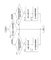
- FIG. 3 is a flowchart showing the indoor air volume restriction control
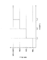
- FIG. 4 is a diagram showing the relationship between the outside air temperature Ta and the air volume upper limit Gcx of the indoor fans 43 and 53 during the cooling operation
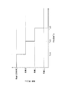
- FIG. It is a figure which shows the relationship between the outdoor temperature Ta at the time of heating operation, and the air volume upper limit Ghx of the indoor fans 43 and 53.
- FIG. The indoor air volume restriction control of the indoor fans 43 and 53 is performed by the indoor capacity control means 82 of the control unit 8.
- step ST0 it is determined whether the current air conditioning operation is a cooling operation or a heating operation.
- step ST0 if it is determined that the current air conditioning operation is the cooling operation, the process proceeds to step ST1, and if it is determined that the current air conditioning operation is the heating operation, step ST11. Move on to processing.
- steps ST1 and ST11 it is determined whether or not it is necessary to forcibly limit the air volume setting of the indoor fans 43 and 53 to the low air volume side according to the outside air temperature Ta.
- the outside air temperature Ta during the cooling operation is equal to or lower than the third outside air temperature Ta3.
- the third outside air temperature Ta3 is a threshold value as to whether or not the air volume upper limit Gcx of the indoor fans 43 and 53 during the cooling operation is limited from the air volume H (that is, no air volume limitation) to the air volume M (see FIG. 4).
- the outside air temperature Ta is equal to or higher than the fourth outside air temperature Ta4.
- the fourth outside air temperature Ta4 is a threshold value as to whether or not the air volume upper limit Ghx of the indoor fans 43 and 53 during the heating operation is limited from the air volume H (that is, no air volume restriction) to the air volume M (see FIG. 5). . If it is determined in steps ST1 and ST11 that the air volume setting of the indoor fans 43 and 53 needs to be forcibly limited to the low air volume side according to the outside air temperature Ta, the processing in steps ST2 and ST12 is performed. Transition. On the other hand, if it is determined in steps ST1 and ST11 that it is not necessary to forcibly limit the air volume setting of the indoor fans 43 and 53 to the low air volume side according to the outside air temperature Ta, the air volume of the indoor fans 43 and 53 is determined.
- the setting is not limited (substantially, the air volume upper limits Gcx and Ghx become the air volume H). For this reason, the cooling operation or the heating operation is continued while the air volume settings of the indoor fans 43 and 53 that are manually instructed from the remote controllers 48 and 58 are maintained.
- the air volume upper limits Gcx and Ghx of the indoor fans 43 and 53 that can be changed according to the outside air temperature Ta are determined. Specifically, during the cooling operation, as shown in FIG. 4, when the outside air temperature Ta is between the second outside air temperature Ta2 and the third outside air temperature Ta3, the air amount upper limit Gcx is set to the air amount M, and the outside air When the temperature Ta is a temperature between the first outside air temperature Ta1 and the second outside air temperature Ta2, the air volume upper limit Gcx is set to the air volume L, and when the outside air temperature Ta is equal to or lower than the first outside air temperature Ta1, The air volume upper limit Gcx is set to the air volume LL.
- the air volume upper limit Gcx of the indoor fans 43 and 53 is decreased according to the decrease in the outside air temperature Ta.
- the air volume upper limit Ghx is set to the air volume M
- the outside air temperature Ta is When the temperature is between the fifth outside air temperature Ta5 and the sixth outside air temperature Ta6, the air volume upper limit Ghx is set to the air volume L, and when the outside air temperature Ta is a temperature equal to or higher than the sixth outside air temperature Ta6, the air volume upper limit Ghx.
- the air volume upper limit Ghx of the indoor fans 43 and 53 is decreased according to the increase in the outside air temperature Ta.
- step ST2 and step ST12 after determining the air volume upper limits Gcx and Ghx of the indoor fans 43 and 53 that can be changed according to the outside air temperature Ta, the process proceeds to steps ST3 and ST13, and the indoor fan 43 , 53 is performed to restrict the air volume setting to the low air volume side according to the outside air temperature Ta. That is, the air volume upper limits Gcx and Ghx of the indoor fans 43 and 53 are set to the air volumes determined in step ST2 and step ST12. For example, when the outside air temperature Ta is a temperature between the first outside air temperature Ta1 and the second outside air temperature Ta2, and the air volume setting of the indoor fans 43 and 53 is manually instructed to the air volume H from the remote controllers 48 and 58. Assume the case of cooling operation.
- the air volume setting of the indoor fans 43 and 53 is limited from the manually instructed air volume H to the air volume L that is the air volume upper limit Gcx.
- the outside air temperature Ta is a temperature between the fifth outside air temperature Ta5 and the sixth outside air temperature Ta6, and the air volume setting of the indoor fans 43 and 53 is manually instructed to the air volume H from the remote controllers 48 and 58.
- the air volume upper limit Ghx becomes the air volume L in step ST12
- the air volume setting of the indoor fans 43 and 53 is limited from the manually instructed air volume H to the air volume L that is the air volume upper limit Ghx.
- the indoor air volume restriction control is performed in a state where the air volume setting of the indoor fans 43 and 53 is manually instructed, so that the air volume of the indoor fans 43 and 53 is unnecessarily large as viewed from the outside air temperature Ta. In the state, the air volume of the indoor fans 43 and 53 can be forcibly reduced.
- the indoor air volume restriction control is performed by providing the air volume upper limit Gcx, Ghx of the indoor fans 43, 53. Therefore, the air volume setting of the indoor fans 43, 53 instructed manually is performed. Is higher than the air volume upper limits Gcx and Ghx, the air volume setting of the indoor fans 43 and 53 can be forcibly reduced to the air volume upper limits Gcx and Ghx. On the other hand, if the air volume setting of the indoor fans 43 and 53 that are manually instructed is equal to or less than the air volume upper limits Gcx and Ghx, the air volume settings of the indoor fans 43 and 53 are set manually. The air volume setting can be maintained.
- the indoor air volume restriction control can be performed while maintaining the air volume settings of the indoor fans 43 and 53 that are manually instructed as much as possible.
- the indoor air volume restriction control as described above has the advantages as described above, it generates a case where the air volume setting of the indoor fans 43 and 53 that the user manually instructs is ignored. There may be users who do not want to apply the control.
- the indoor air volume restriction setting means 83 is provided in the control unit 8. ing.
- the indoor air volume restriction setting unit 83 is a memory provided in the outdoor control unit 37 of the control unit 8, and the indoor air volume is set by communication from an external device for performing various control settings of the air conditioner 1. It is possible to set whether or not to apply the limit control, the relationship value between the outside air temperature Ta and the air volume upper limits Gcx and Ghx, and the like.
- the indoor air volume restriction setting unit 83 is not limited to the above-described one. For example, whether the indoor air volume restriction control is applied, such as a dip switch provided in the outdoor control unit 37, or the outside air. Any value can be used as long as it can set the relationship value of the temperature Ta-air volume upper limit Gcx, Ghx.
- FIG. 6 is a flowchart showing a main part of the indoor air volume restriction control according to the present modification.
- the indoor air volume restriction control of the indoor fans 43 and 53 is performed by the indoor capacity control means 82 of the control unit 8 as in the above embodiment.
- processing in steps ST4 and ST14 is added to determine whether or not the room temperatures Tra and Trb are away from the target indoor temperatures Tras and Trbs. judge.
- the temperature difference obtained by subtracting the target room temperature Tras, Trbs from the room temperature Tra, Trb during the cooling operation, or the room temperature difference ⁇ Tr obtained by subtracting the room temperature Tra, Trb from the target room temperature Tras, Trbs during the heating operation. Is greater than or equal to the air flow restriction relaxation temperature difference ⁇ Trs.
- Steps ST4 and ST14 when it is determined that the indoor temperature difference ⁇ Tr is equal to or larger than the air flow restriction relaxation temperature difference ⁇ Trs, Steps ST5 and ST15 are added, and the process proceeds to Steps ST5 and ST15. .
- the air volume upper limits Gcx and Ghx of the indoor fans 43 and 53 set in steps ST3 and ST13 are set. maintain.
- steps ST5 and ST15 the air volume upper limits Gcx and Ghx of the indoor fans 43 and 53 are relaxed.
- the air volume is increased by one or more steps from the air volume upper limits Gcx and Ghx of the indoor fans 43 and 53 set in steps ST3 and ST13.
- the outside air temperature Ta is a temperature between the first outside air temperature Ta1 and the second outside air temperature Ta2
- the air volume setting of the indoor fans 43 and 53 is manually instructed to the air volume H from the remote controllers 48 and 58. Assume the case of cooling operation.
- the air volume upper limit Gcx becomes the air volume L in step ST2
- the air volume setting of the indoor fans 43 and 53 is limited from the manually instructed air volume H to the air volume L that is the air volume upper limit Gcx in step ST3.
- the air volume upper limit Gcx is increased from the air volume L to the air volume M in step ST5, thereby reducing the low air volume side. The restrictions on are relaxed.
- the outside air temperature Ta is a temperature between the fifth outside air temperature Ta5 and the sixth outside air temperature Ta6, and the air volume setting of the indoor fans 43 and 53 is manually instructed to the air volume H from the remote controllers 48 and 58. Assume a case of heating operation. In this case, since the air volume upper limit Ghx becomes the air volume L in step ST12, the air volume setting of the indoor fans 43 and 53 is limited from the manually instructed air volume H to the air volume L that is the air volume upper limit Ghx.
- step ST14 if it is determined in step ST14 that the indoor temperature difference ⁇ Tr is equal to or larger than the air volume restriction relaxation temperature difference ⁇ Trs, the air volume upper limit Ghx is increased from the air volume L to the air volume M in step ST15, thereby reducing the low air volume side. The restrictions on are relaxed.
- the indoor air volume restriction control can be appropriately performed in consideration of not only the outside air temperature Ta but also changes in the indoor temperatures Tra and Trb.
- the indoor air volume restriction control is performed, and the indoor temperature Tra When the Trb is away from the target indoor temperatures Tras and Trbs, the indoor air volume restriction control is not performed.
- FIG. 7 is a flowchart showing a main part of the indoor air volume restriction control according to the present modification.
- the indoor air volume restriction control of the indoor fans 43 and 53 is performed by the indoor capacity control means 82 of the control unit 8 in the same manner as in the above embodiment and the modified example ⁇ A>.
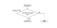
- steps ST6 and ST16 are performed.
- a process is added to determine whether the room temperatures Tra and Trb are close to the target room temperatures Tras and Trbs.
- steps ST6 and ST16 If it is determined in steps ST6 and ST16 that the indoor temperature difference ⁇ Tr is equal to or smaller than the air volume restriction allowable temperature difference ⁇ Trss, the process proceeds to steps ST2 and ST12. On the other hand, if it is determined in steps ST6 and ST16 that the indoor temperature difference ⁇ Tr is larger than the air volume restriction allowable temperature difference ⁇ Trss, the air flow setting of the indoor fans 43 and 53 is not limited, and the remote controllers 48 and 58 are used. The cooling operation and the heating operation are continued while maintaining the air volume settings of the indoor fans 43 and 53 that are manually instructed.
- the indoor air volume restriction control can be appropriately performed in consideration of not only the outside air temperature Ta but also the indoor air conditioning load.
- the determination of the indoor temperature difference ⁇ Tr in step ST6 and step ST16 may be made by each indoor unit 4, 5 or the representative value of the indoor temperature difference ⁇ Tr of the indoor units 4, 5 is used. You may determine collectively. For example, it may be determined whether the average value of the indoor temperature differences ⁇ Tr of the indoor units 4 and 5 is equal to or less than the air volume restriction allowable temperature difference ⁇ Trss. Further, it may be determined whether or not the maximum value of the indoor temperature difference ⁇ Tr of the indoor units 4 and 5 is equal to or less than the air volume restriction allowable temperature difference ⁇ Trss.
- the minimum value of the indoor temperature difference ⁇ Tr of the indoor units 4 and 5 is equal to or less than the air volume restriction allowable temperature difference ⁇ Trss. Further, it may be determined whether or not the weighted average value of the indoor temperature difference ⁇ Tr of the indoor units 4 and 5 is equal to or less than the air volume restriction allowable temperature difference ⁇ Trss.
- the weighted average value a value in consideration of the operating capacity of each indoor unit 4, 5, for example, ⁇ (operating capacity of each indoor unit ⁇ indoor temperature difference ⁇ Tr) ⁇ number of indoor units can be used.
- the indoor air conditioning load is determined by the openings MVa and MVb of the indoor expansion valves 41 and 51 as the indoor flow control valves that increase as the flow rate of the refrigerant flowing through the indoor heat exchangers 42 and 52 increases. Whether or not is large is determined.
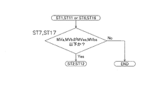
- FIG. 8 is a flowchart showing a main part of the indoor air volume restriction control according to the present modification.
- the indoor air volume restriction control of the indoor fans 43 and 53 is performed by the indoor capacity control means 82 of the control unit 8 in the same manner as in the above embodiment and the modified examples ⁇ A> and ⁇ B>.
- steps ST1 and ST11 when it is determined in steps ST1 and ST11 that it is necessary to forcibly limit the air volume setting of the indoor fans 43 and 53 to the low air volume side according to the outside air temperature Ta, or In addition to the determination in ST11, in steps ST6 and ST16, when it is determined that the room temperature Tra, Trb is close to the target room temperature Tras, Trbs, the process in steps ST7 and ST17 is added to add an indoor flow rate control valve. It is determined whether or not the opening MVa and MVb of the indoor expansion valves 41 and 51 are equal to or less than the air volume restriction permission opening MVas and MVbs.
- Steps ST7 and ST17 when it is determined that the opening MVa and MVb of the indoor expansion valves 41 and 51 as the indoor flow control valves are equal to or less than the air volume restriction permission opening MVas and MVbs, Steps ST2 and ST12 are performed. Move on to processing. On the other hand, if it is determined in step ST7 and step ST17 that the openings MVa and MVb of the indoor expansion valves 41 and 51 as the indoor flow control valves are larger than the air volume restriction permission openings MVas and MVbs, the indoor fan 43 The air flow setting of the indoor fans 43 and 53 manually instructed from the remote controllers 48 and 58 is maintained, and the cooling operation and the heating operation are continued without restricting the air flow setting of 53 and 53.
- the indoor air volume restriction control can be appropriately performed in consideration of not only the outside air temperature Ta but also the indoor air conditioning load.
- limiting control is performed by providing the air volume upper limit of the indoor fans 43 and 53 which can be changed according to the outside temperature Ta, it is not limited to this. Absent.
- the air volume setting of the indoor fans 43 and 53 instructed manually may be decreased to one or more lower air volume sides when it is determined that the indoor air volume restriction control is necessary.
- each indoor unit 4, 5 has applied this invention to the air conditioning apparatus 1 which has the indoor expansion valves 41 and 51 as an indoor flow control valve, it is limited to this. Instead, the present invention may be applied to an air conditioner that has indoor expansion valves 41 and 51 as indoor flow control valves in the outdoor unit 2.
- the present invention is widely applicable to an air conditioner capable of manually instructing the air volume setting of an indoor fan.
Landscapes
- Engineering & Computer Science (AREA)
- Chemical & Material Sciences (AREA)
- Combustion & Propulsion (AREA)
- Mechanical Engineering (AREA)
- General Engineering & Computer Science (AREA)
- Physics & Mathematics (AREA)
- Fluid Mechanics (AREA)
- Air Conditioning Control Device (AREA)
Abstract
空気調和装置(1)は、室外ユニット(2)と、室内熱交換器(42、52)及び室内ファン(43、53)を有する室内ユニット(4、5)とを備えており、室内ファン(43、53)の風量設定を手動で指示可能である。そして、ここでは、室内ファン(43、53)の風量設定を手動で指示した状態で、室内ファン(43、53)の風量設定を外気温度に応じて強制的に低風量側に制限する室内風量制限制御を行う。
Description
本発明は、空気調和装置、特に、室内ファンの風量設定を手動で指示可能な空気調和装置に関する。
従来より、室外ユニットと室内ユニットとを有しており、冷房運転時における冷媒の蒸発温度や暖房運転時における冷媒の凝縮温度が目標蒸発温度や目標凝縮温度になるように圧縮機の容量制御を行う空気調和装置がある。そして、このような空気調和装置として、特許文献1(特開2002-147823号公報)に示すような、目標蒸発温度や目標凝縮温度を外気温度に応じて変化させるようにしたものがある。
上記特許文献1の空気調和装置では、目標蒸発温度や目標凝縮温度を外気温度に応じて変化させつつ圧縮機の容量制御を行うようにしているため、圧縮機の消費動力を低減することができる。これにより、圧縮機の消費動力の低減による通年エネルギー消費効率(APF)の向上は図ることができる。
しかし、上記特許文献1の空気調和装置では、室内ユニットにおける室内ファンの風量設定がリモートコントローラなどで手動指示された状態になっていると、不必要に風量が多い場合であっても、手動指示された風量設定が維持されてしまい、室内ファンが無駄に動力を消費してしまい、APFの向上が不十分になるおそれがある。
本発明の課題は、室内ファンの風量設定を手動で指示可能な空気調和装置において、無駄な室内ファンの消費動力を低減して、APFの向上を図ることにある。
第1の観点にかかる空気調和装置は、室外ユニットと、室内熱交換器及び室内ファンを有する室内ユニットとを備えており、室内ファンの風量設定を手動で指示可能な空気調和装置である。そして、ここでは、室内ファンの風量設定を手動で指示した状態で、室内ファンの風量設定を外気温度に応じて強制的に低風量側に制限する室内風量制限制御を行うようにしている。
ここでは、上記のように、室内ファンの風量設定が手動指示された状態で室内風量制限制御を行うことによって、外気温度から見て不必要に室内ファンの風量が多い状態である場合に、室内ファンの風量を強制的に少なくすることができる。
これにより、ここでは、無駄な室内ファンの消費動力を低減して、APFの向上を図ることができる。
第2の観点にかかる空気調和装置は、第1の観点にかかる空気調和装置において、室外ユニット又は室内ユニットが、室内熱交換器を流れる冷媒の流量を調節する室内流量調節弁を有しており、室内流量調節弁の開度が風量制限許可開度以下である場合に、室内風量制限制御を行う。
室内の空調負荷が大きい場合には、外気温度から見て室内ファンの風量が多い状態であったとしても、室内ファンの風量設定を低風量側に制限することは、室内の空調負荷を処理しにくくするため、この場合に室内風量制限制御を行うことは好ましくない。そして、室内の空調負荷が大きい場合には、室内熱交換器を流れる冷媒の流量が増加する傾向にある。
そこで、ここでは、上記のように、室内熱交換器を流れる冷媒の流量が増加するにつれて大きくなる室内流量調節弁の開度によって、室内の空調負荷が大きい場合であるかどうかを判定するようにしている。
これにより、ここでは、外気温度だけでなく室内の空調負荷も考慮した上で、適切に室内風量制限制御を行うことができる。
第3の観点にかかる空気調和装置は、第1又は第2の観点にかかる空気調和装置において、外気温度に応じて変更可能な室内ファンの風量上限を設け、室内ファンの風量上限を低下させることによって室内風量制限制御を行う。
第4の観点にかかる空気調和装置は、第3の観点にかかる空気調和装置において、冷房運転時には、外気温度の低下に応じて室内ファンの風量上限を低下させ、及び/又は、暖房運転時には、外気温度の上昇に応じて室内ファンの風量上限を低下させる。
ここでは、上記のように、室内ファンの風量上限を設けることで室内風量制限制御を行うようにしているため、手動で指示された室内ファンの風量設定が風量上限よりも高風量である場合に、室内ファンの風量設定を強制的に風量上限まで低下させることができる。一方、手動で指示された室内ファンの風量設定が風量上限以下の風量である場合には、室内ファンの風量設定を手動で指示された室内ファンの風量設定のままで維持することができる。
これにより、ここでは、手動で指示された室内ファンの風量設定をできるだけ維持しながら、室内風量制限制御を行うことができる。
第5の観点にかかる空気調和装置は、第1~第4の観点の空気調和装置のいずれかにおいて、室内温度が目標室内温度から離れる場合には、室内ファンの風量設定の低風量側への制限を緩和する。
室内風量制限制御を行っている際に、室内の空調負荷が大きくなる等の運転状況の変化が発生すると、室内温度が目標室内温度から離れる場合があるため、この場合に室内ファンの風量設定を低風量側に過度に制限したままにすることは好ましくない。
そこで、ここでは、上記のように、室内温度が目標室内温度から離れる場合には、室内ファンの風量設定の低風量側への制限を緩和するようにしている。
これにより、ここでは、外気温度だけでなく室内温度の変化も考慮した上で、適切に室内風量制限制御を行うことができる。
以下、本発明にかかる空気調和装置の実施形態について、図面に基づいて説明する。尚、本発明にかかる空気調和装置の実施形態の具体的な構成は、下記の実施形態及びその変形例に限られるものではなく、発明の要旨を逸脱しない範囲で変更可能である。
(1)空気調和装置の基本構成
図1は、本発明の一実施形態にかかる空気調和装置1の概略構成図である。空気調和装置1は、蒸気圧縮式の冷凍サイクル運転を行うことによって、ビル等の屋内の空調に使用される装置である。空気調和装置1は、主として、室外ユニット2と、複数(ここでは、2台)の室内ユニット4、5とが接続されることによって構成されている。ここで、室外ユニット2と複数の室内ユニット4、5とは、液冷媒連絡管6及びガス冷媒連絡管7を介して接続されている。すなわち、空気調和装置1の蒸気圧縮式の冷媒回路10は、室外ユニット2と、複数の室内ユニット4、5とが冷媒連絡管6、7を介して接続されることによって構成されている。
図1は、本発明の一実施形態にかかる空気調和装置1の概略構成図である。空気調和装置1は、蒸気圧縮式の冷凍サイクル運転を行うことによって、ビル等の屋内の空調に使用される装置である。空気調和装置1は、主として、室外ユニット2と、複数(ここでは、2台)の室内ユニット4、5とが接続されることによって構成されている。ここで、室外ユニット2と複数の室内ユニット4、5とは、液冷媒連絡管6及びガス冷媒連絡管7を介して接続されている。すなわち、空気調和装置1の蒸気圧縮式の冷媒回路10は、室外ユニット2と、複数の室内ユニット4、5とが冷媒連絡管6、7を介して接続されることによって構成されている。
<室内ユニット>
室内ユニット4、5は、屋内に設置されている。室内ユニット4、5は、冷媒連絡管6、7を介して室外ユニット2に接続されており、冷媒回路10の一部を構成している。
室内ユニット4、5は、屋内に設置されている。室内ユニット4、5は、冷媒連絡管6、7を介して室外ユニット2に接続されており、冷媒回路10の一部を構成している。
次に、室内ユニット4、5の構成について説明する。尚、室内ユニット5は、室内ユニット4と同様の構成を有するため、ここでは、室内ユニット4の構成のみ説明し、室内ユニット5の構成については、それぞれ、室内ユニット4の各部を示す符号を40番台から50番台に読み替えて、各部の説明を省略する。
室内ユニット4は、主として、冷媒回路10の一部を構成する室内側冷媒回路10a(室内ユニット5では、室内側冷媒回路10b)を有している。室内側冷媒回路10aは、主として、室内膨張弁41と、室内熱交換器42とを有している。
室内膨張弁41は、室内側冷媒回路10aを流れる冷媒を減圧して冷媒の流量の調節する室内流量調節弁である。室内膨張弁41は、室内熱交換器42の液側に接続された電動膨張弁である。
室内熱交換器42は、例えば、クロスフィン式のフィン・アンド・チューブ型熱交換器からなる。室内熱交換器42の近傍には、室内熱交換器42に室内空気を送るための室内ファン43が設けられている。室内ファン43によって室内熱交換器42に対して室内空気を送風することにより、室内熱交換器42では、冷媒と室内空気との間で熱交換が行われる。室内ファン43は、室内ファンモータ43aによって回転駆動されるようになっている。これにより、室内熱交換器42は、冷媒の放熱器や冷媒の蒸発器として機能するようになっている。また、室内ファンモータ43aは、回転数を変化させることによって、室内ファン43の風量を可変することが可能になっている。ここでは、室内ファン43の風量は、室内ファンモータ43aの回転数を変更することによって、最も回転数が大きく大風量の風量H、風量Hの回転数よりも小さく中程度の風量の風量M、風量Mの回転数よりもさら小さく小風量の風量L、及び、風量Lの回転数よりもさら小さく最小風量の風量LLの間で4段階に変更可能である。ここで、風量H、風量M、及び、風量Lの3つの風量設定は、リモートコントローラ48から手動で指示可能であるが、風量LLは、リモートコントローラ48からの手動で指示することができない。尚、ここでは、室内ファン43の風量設定は、風量LLを含めて風量H、風量M、及び、風量Lの4段階で切り換えられるが、5段階以上であってもよい。
また、室内ユニット4には、各種のセンサが設けられている。室内熱交換器42の液側には、液状態又は気液二相状態の冷媒の温度Trla(室外ユニット5では、Trlb)を検出する液側温度センサ44が設けられている。室内熱交換器42のガス側には、ガス状態の冷媒の温度Trga(室外ユニット5では、Trgb)を検出するガス側温度センサ45が設けられている。室内ユニット4には、室内ユニット4が対象とする空調空間の室内空気の温度、すなわち、室内温度Tra(室外ユニット5では、Trb)を検出する室内温度センサ46が設けられている。また、室内ユニット4は、室内ユニット4を構成する各部の動作を制御する室内側制御部47を有している。そして、室内側制御部47は、室内ユニット4の制御を行うために設けられたマイクロコンピュータやメモリ等を有しており、室内ユニット4を個別に操作するためのリモートコントローラ48との間で制御信号等のやりとりを行ったり、室外ユニット2との間で制御信号等のやりとりを行うことができるようになっている。尚、リモートコントローラ48は、手動による室内ファン43の風量設定を含む空調運転に関する各種指示や運転/停止指示を行う機器である。
<室外ユニット>
室外ユニット2は、屋外に設置されている。室外ユニット2は、冷媒連絡管6、7を介して室内ユニット4、5に接続されており、冷媒回路10の一部を構成している。
室外ユニット2は、屋外に設置されている。室外ユニット2は、冷媒連絡管6、7を介して室内ユニット4、5に接続されており、冷媒回路10の一部を構成している。
次に、室外ユニット2の構成について説明する。
室外ユニット2は、主として、冷媒回路10の一部を構成する室外側冷媒回路10cを有している。この室外側冷媒回路10cは、主として、圧縮機21と、切換機構22と、室外熱交換器23と、室外膨張弁24とを有している。
圧縮機21は、ケーシング内に図示しない圧縮要素及び圧縮要素を回転駆動する圧縮機モータ21aが収容された密閉型圧縮機である。圧縮機モータ21aは、図示しないインバータ装置を介して電力が供給されるようになっており、インバータ装置の周波数(すなわち、回転数)を変化させることによって、運転容量を可変することが可能になっている。
切換機構22は、冷媒の流れの方向を切り換えるための四路切換弁である。切換機構22は、空調運転の1つとしての冷房運転時には、室外熱交換器23を圧縮機21において圧縮された冷媒の放熱器として、かつ、室内熱交換器42、52を室外熱交換器23において放熱した冷媒の蒸発器として機能させるために、圧縮機21の吐出側と室外熱交換器23のガス側とを接続するとともに圧縮機21の吸入側とガス冷媒連絡管7とを接続し(放熱切換状態、図1の切換機構22の実線を参照)、空調運転の1つとしての暖房運転時には、室内熱交換器42、52を圧縮機21において圧縮された冷媒の放熱器として、かつ、室外熱交換器23を室内熱交換器42、52において放熱した冷媒の蒸発器として機能させるために、圧縮機21の吐出側とガス冷媒連絡管7とを接続するとともに圧縮機21の吸入側と室外熱交換器23のガス側とを接続することが可能である(蒸発切換状態、図1の切換機構22の破線を参照)。尚、切換機構22は、四路切換弁ではなく、三方弁や電磁弁等を組み合わせて同じ機能を果たすように構成したものであってもよい。
室外熱交換器23は、例えば、クロスフィン式のフィン・アンド・チューブ型熱交換器からなる。室外熱交換器23の近傍には、室外熱交換器23に室外空気を送るための室外ファン25が設けられている。室外ファン25によって室外熱交換器23に対して室外空気を送風することにより、室外熱交換器23では、冷媒と室外空気との間で熱交換が行われる。室外ファン25は、室外ファンモータ25aによって回転駆動されるようになっている。これにより、室外熱交換器23は、冷媒の放熱器や冷媒の蒸発器として機能するようになっている。
室外膨張弁24は、室外側冷媒回路10cを流れる冷媒を減圧する弁である。室外膨張弁24は、室外熱交換器23の液側に接続された電動膨張弁である。
また、室外ユニット2には、各種のセンサが設けられている。室外ユニット2には、圧縮機21の吸入圧力Psを検出する吸入圧力センサ31と、圧縮機21の吐出圧力Pdを検出する吐出圧力センサ32と、圧縮機21の吸入温度Tsを検出する吸入温度センサ33と、圧縮機21の吐出温度Tdを検出する吐出温度センサ34とが設けられている。室外熱交換器23には、気液二相状態の冷媒の温度Tolを検出する室外熱交温度センサ35が設けられている。室外ユニット2には、室外ユニット2が配置される外部空間の室外空気の温度、すなわち、外気温度Taを検出する室外温度センサ36が設けられている。また、室外ユニット2は、室外ユニット2を構成する各部の動作を制御する室外側制御部37を有している。そして、室外側制御部37は、室外ユニット2の制御を行うために設けられたマイクロコンピュータ、メモリや圧縮機モータ21aを制御するインバータ装置等を有しており、室内ユニット4、5の室内側制御部47、57との間で制御信号等のやりとりを行うことができるようになっている。
<冷媒連絡管>
冷媒連絡管6、7は、空気調和装置1を設置する際に、現地にて施工される冷媒管であり、室外ユニット2及び室内ユニット4、5の設置条件に応じて種々の長さや管径を有するものが使用される。
冷媒連絡管6、7は、空気調和装置1を設置する際に、現地にて施工される冷媒管であり、室外ユニット2及び室内ユニット4、5の設置条件に応じて種々の長さや管径を有するものが使用される。
<制御部>
室内ユニット4、5を個別に操作するためのリモートコントローラ48、58と、室内ユニット4、5の室内側制御部47、57と、室外ユニット2の室外側制御部37とは、図1に示すように、空気調和装置1全体の運転制御を行う制御部8を構成している。制御部8は、図2に示されるように、各種センサ31~36、44~46、54~56等の検出信号を受けることができるように接続されている。そして、制御部8は、これらの検出信号等に基づいて各種機器及び弁21a、22、24、26、41、51、43a、53aを制御することによって、空調運転(冷房運転及び暖房運転)を行うことができるように構成されている。また、ここでは、制御部8は、主として、室外能力制御手段81と、室内能力制御手段82とを有している。室外能力制御手段81は、冷媒回路10における冷媒の蒸発温度Te又は凝縮温度Tcが目標蒸発温度Tes又は目標凝縮温度Tcsになるように室外ユニット2の空調能力を制御する手段である。室内能力制御手段82は、各室内ユニット4、5が対象とする空調空間の室内温度Tra、Trbが目標室内温度Tras、Trbsになるように各室内ユニット4、5の機器及び弁41、43a、51、53aを制御する手段である。ここで、図2は、空気調和装置1の制御ブロック図である。
室内ユニット4、5を個別に操作するためのリモートコントローラ48、58と、室内ユニット4、5の室内側制御部47、57と、室外ユニット2の室外側制御部37とは、図1に示すように、空気調和装置1全体の運転制御を行う制御部8を構成している。制御部8は、図2に示されるように、各種センサ31~36、44~46、54~56等の検出信号を受けることができるように接続されている。そして、制御部8は、これらの検出信号等に基づいて各種機器及び弁21a、22、24、26、41、51、43a、53aを制御することによって、空調運転(冷房運転及び暖房運転)を行うことができるように構成されている。また、ここでは、制御部8は、主として、室外能力制御手段81と、室内能力制御手段82とを有している。室外能力制御手段81は、冷媒回路10における冷媒の蒸発温度Te又は凝縮温度Tcが目標蒸発温度Tes又は目標凝縮温度Tcsになるように室外ユニット2の空調能力を制御する手段である。室内能力制御手段82は、各室内ユニット4、5が対象とする空調空間の室内温度Tra、Trbが目標室内温度Tras、Trbsになるように各室内ユニット4、5の機器及び弁41、43a、51、53aを制御する手段である。ここで、図2は、空気調和装置1の制御ブロック図である。
以上のように、空気調和装置1は、複数(ここでは、2台)の室内ユニット4、5が室外ユニット2に接続されることによって構成される冷媒回路10を有している。また、空気調和装置1は、室内ユニット4、5に室内熱交換器42、52及び室内ファン43、53を有しており、室内ファン43、53の風量設定を手動で指示可能になっている。そして、空気調和装置1では、制御部8によって、以下のような空調運転及び制御が行われるようになっている。
(2)空気調和装置の基本動作及び基本制御
次に、空気調和装置1の空調運転(冷房運転及び暖房運転)の基本動作について、図1を用いて説明する。
次に、空気調和装置1の空調運転(冷房運転及び暖房運転)の基本動作について、図1を用いて説明する。
<冷房運転>
リモートコントローラ48、58から冷房運転の指示がなされると、切換機構22が放熱運転状態(図1の切換機構22の実線で示された状態)に切り換えられて、圧縮機21、室外ファン25及び室内ファン43、53が起動する。ここでは、室内ファン43、53の風量設定は、ユーザーの嗜好に応じて、リモートコントローラ48、58から風量H、風量M、及び、風量Lのいずれかに手動で指示されている。
リモートコントローラ48、58から冷房運転の指示がなされると、切換機構22が放熱運転状態(図1の切換機構22の実線で示された状態)に切り換えられて、圧縮機21、室外ファン25及び室内ファン43、53が起動する。ここでは、室内ファン43、53の風量設定は、ユーザーの嗜好に応じて、リモートコントローラ48、58から風量H、風量M、及び、風量Lのいずれかに手動で指示されている。
すると、冷媒回路10内の低圧のガス冷媒は、圧縮機21に吸入されて圧縮されて高圧のガス冷媒となる。この高圧のガス冷媒は、切換機構22を経由して室外熱交換器23に送られる。室外熱交換器23に送られた高圧のガス冷媒は、冷媒の放熱器として機能する室外熱交換器23において、室外ファン25によって供給される室外空気と熱交換を行って冷却されることによって凝縮して、高圧の液冷媒となる。この高圧の液冷媒は、室外膨張弁24及び液冷媒連絡管6を経由して、室外ユニット2から室内ユニット4、5に送られる。
室内ユニット4、5に送られた高圧の液冷媒は、室内膨張弁41、51によって減圧されて、低圧の気液二相状態の冷媒となる。この低圧の気液二相状態の冷媒は、室内熱交換器42、52に送られる。室内熱交換器42、52に送られた低圧の気液二相状態の冷媒は、冷媒の蒸発器として機能する室内熱交換器42、52において、室内ファン43、53によって供給される室内空気と熱交換を行って加熱されることによって蒸発して、低圧のガス冷媒となる。この低圧のガス冷媒は、ガス冷媒連絡管7を経由して、室内ユニット4、5から室外ユニット2に送られる。
室外ユニット2に送られた低圧のガス冷媒は、切換機構22を経由して、再び、圧縮機21に吸入される。
<暖房運転>
リモートコントローラ48、58から暖房運転の指示がなされると、切換機構22が蒸発運転状態(図1の切換機構22の破線で示された状態)に切り換えられて、圧縮機21、室外ファン25及び室内ファン43、53が起動する。ここでは、室内ファン43、53の風量設定は、ユーザーの嗜好に応じて、リモートコントローラ48、58から風量H、風量M、及び、風量Lのいずれかに手動で指示されている。
リモートコントローラ48、58から暖房運転の指示がなされると、切換機構22が蒸発運転状態(図1の切換機構22の破線で示された状態)に切り換えられて、圧縮機21、室外ファン25及び室内ファン43、53が起動する。ここでは、室内ファン43、53の風量設定は、ユーザーの嗜好に応じて、リモートコントローラ48、58から風量H、風量M、及び、風量Lのいずれかに手動で指示されている。
すると、冷媒回路10内の低圧のガス冷媒は、圧縮機21に吸入されて圧縮されて高圧のガス冷媒となる。この高圧のガス冷媒は、切換機構22及びガス冷媒連絡管7を経由して、室外ユニット2から室内ユニット4、5に送られる。
室内ユニット4、5に送られた高圧のガス冷媒は、室内熱交換器42、52に送られる。室内熱交換器42、52に送られた高圧のガス冷媒は、冷媒の放熱器として機能する室内熱交換器42、52において、室内ファン43、53によって供給される室内空気と熱交換を行って冷却されることによって凝縮して、高圧の液冷媒となる。この高圧の液冷媒は、室内膨張弁41、51によって減圧される。室内膨張弁41、51によって減圧された冷媒は、液冷媒連絡管6を経由して、室内ユニット4、5から室外ユニット2に送られる。
室外ユニット2に送られた冷媒は、室外膨張弁24に送られ、室外膨張弁24によって減圧されて、低圧の気液二相状態の冷媒となる。この低圧の気液二相状態の冷媒は、室外熱交換器23に送られる。室外熱交換器23に送られた低圧の気液二相状態の冷媒は、冷媒の蒸発器として機能する室外熱交換器23において、室外ファン25によって供給される室外空気と熱交換を行って加熱されることによって蒸発して、低圧のガス冷媒となる。この低圧のガス冷媒は、切換機構22を経由して、再び、圧縮機21に吸入される。
<基本制御>
上記の空調運転(冷房運転及び暖房運転)においては、まず、冷媒回路10における冷媒の蒸発温度Te又は凝縮温度Tcが目標蒸発温度Tes又は目標凝縮温度Tcsになるように室外ユニット2の空調能力が制御される。また、各室内ユニット4、5における室内温度Tra、Trbが、各室内ユニット4、5が対象とする空調空間の室内温度Tra、Trbが目標室内温度Tras、Trbsになるように各室内ユニット4、5の室内膨張弁41、51が制御される。尚、各室内ユニット4、5における目標室内温度Tras、Trbsの設定は、リモートコントローラ48、58によって行われる。また、室外ユニット2の空調能力制御は、制御部8の室外能力制御手段81によって行われ、各室内ユニット4、5の空調能力制御は、制御部8の室内能力制御手段82によって行われる。
上記の空調運転(冷房運転及び暖房運転)においては、まず、冷媒回路10における冷媒の蒸発温度Te又は凝縮温度Tcが目標蒸発温度Tes又は目標凝縮温度Tcsになるように室外ユニット2の空調能力が制御される。また、各室内ユニット4、5における室内温度Tra、Trbが、各室内ユニット4、5が対象とする空調空間の室内温度Tra、Trbが目標室内温度Tras、Trbsになるように各室内ユニット4、5の室内膨張弁41、51が制御される。尚、各室内ユニット4、5における目標室内温度Tras、Trbsの設定は、リモートコントローラ48、58によって行われる。また、室外ユニット2の空調能力制御は、制御部8の室外能力制御手段81によって行われ、各室内ユニット4、5の空調能力制御は、制御部8の室内能力制御手段82によって行われる。
-冷房運転時-
空調運転が冷房運転である場合において、制御部8の室内能力制御手段82は、各室内熱交換器42、52の出口における冷媒の過熱度SHra、SHrbが目標過熱度SHras、SHrbsになるように、各室内膨張弁41、51の開度を制御している(以下、この制御を「室内膨張弁による過熱度制御」とする)。ここで、過熱度SHra、SHrbは、吸入圧力センサ31によって検出される吸入圧力Ps、及び、ガス側温度センサ45、55によって検出される室内熱交換器42、52のガス側の冷媒の温度Trga、Trgbから算出される。より具体的には、まず、吸入圧力Psを冷媒の飽和温度に換算して、冷媒回路10における蒸発圧力Peに等価な状態量である蒸発温度Teを得る。ここで、蒸発圧力Peとは、冷房運転時において、室内膨張弁41、51の出口から室内熱交換器42、52を経由して圧縮機21の吸入側に至るまでの間を流れる低圧の冷媒を代表する圧力を意味している。そして、各室内熱交換器42、52のガス側の冷媒の温度Trga、Trgbから蒸発温度Teを差し引くことによって過熱度SHra、SHrbを得る。
空調運転が冷房運転である場合において、制御部8の室内能力制御手段82は、各室内熱交換器42、52の出口における冷媒の過熱度SHra、SHrbが目標過熱度SHras、SHrbsになるように、各室内膨張弁41、51の開度を制御している(以下、この制御を「室内膨張弁による過熱度制御」とする)。ここで、過熱度SHra、SHrbは、吸入圧力センサ31によって検出される吸入圧力Ps、及び、ガス側温度センサ45、55によって検出される室内熱交換器42、52のガス側の冷媒の温度Trga、Trgbから算出される。より具体的には、まず、吸入圧力Psを冷媒の飽和温度に換算して、冷媒回路10における蒸発圧力Peに等価な状態量である蒸発温度Teを得る。ここで、蒸発圧力Peとは、冷房運転時において、室内膨張弁41、51の出口から室内熱交換器42、52を経由して圧縮機21の吸入側に至るまでの間を流れる低圧の冷媒を代表する圧力を意味している。そして、各室内熱交換器42、52のガス側の冷媒の温度Trga、Trgbから蒸発温度Teを差し引くことによって過熱度SHra、SHrbを得る。
また、空調運転が冷房運転である場合において、制御部8の室外能力制御手段81は、冷媒回路10における蒸発圧力Peに相当する蒸発温度Teが目標蒸発温度Tesに近づくように、圧縮機21の運転容量を制御している(以下、この制御を「圧縮機による蒸発温度制御」とする)。ここで、圧縮機21の運転容量の制御は、圧縮機モータ21aの周波数を変更することによって行われる。また、ここでは、制御対象の状態量を蒸発温度Teとしているが、蒸発圧力Peであってもよい。この場合には、目標蒸発温度Tesに相当する目標蒸発圧力Pesを使用すればよい。すなわち、蒸発圧力Peと蒸発温度Te、及び、目標蒸発圧力Pesと目標蒸発温度Tesは、文言自体は異なるが、実質的に同じ状態量を意味している。
このように、冷房運転においては、その基本制御として、室内膨張弁41、51による過熱度制御、及び、圧縮機21による蒸発温度制御が行われるようになっている。そして、空気調和装置1では、このような冷房運転の基本制御によって、各室内ユニット4、5における室内温度Tra、Trbが、目標室内温度Tras、Trbsになるようにしている。
-暖房運転時-
空調運転が暖房運転である場合において、制御部8の室内能力制御手段82は、各室内熱交換器42、52の出口における冷媒の過冷却度SCra、SCrbが目標過冷却度SCras、SCrbsになるように、各室内膨張弁41、51の開度を制御している(以下、この制御を「室内膨張弁による過冷却度制御」とする)。ここで、過冷却度SCra、SCrbは、吐出圧力センサ32によって検出される吐出圧力Pd、及び、液側温度センサ44、54によって検出される室内熱交換器42、52の液側の冷媒の温度Trla、Trlbから算出される。より具体的には、まず、吐出圧力Pdを冷媒の飽和温度に換算して、冷媒回路10における凝縮圧力Pcに等価な状態量である凝縮温度Tcを得る。ここで、凝縮圧力Pcとは、暖房運転時において、圧縮機21の吐出側から室内熱交換器42、52を経由して室内膨張弁41、51に至るまでの間を流れる高圧の冷媒を代表する圧力を意味している。そして、凝縮温度Tcから各室内熱交換器42、52の液側の冷媒の温度Trla、Trlbを差し引くことによって過冷却度SCra、SCrbを得る。
空調運転が暖房運転である場合において、制御部8の室内能力制御手段82は、各室内熱交換器42、52の出口における冷媒の過冷却度SCra、SCrbが目標過冷却度SCras、SCrbsになるように、各室内膨張弁41、51の開度を制御している(以下、この制御を「室内膨張弁による過冷却度制御」とする)。ここで、過冷却度SCra、SCrbは、吐出圧力センサ32によって検出される吐出圧力Pd、及び、液側温度センサ44、54によって検出される室内熱交換器42、52の液側の冷媒の温度Trla、Trlbから算出される。より具体的には、まず、吐出圧力Pdを冷媒の飽和温度に換算して、冷媒回路10における凝縮圧力Pcに等価な状態量である凝縮温度Tcを得る。ここで、凝縮圧力Pcとは、暖房運転時において、圧縮機21の吐出側から室内熱交換器42、52を経由して室内膨張弁41、51に至るまでの間を流れる高圧の冷媒を代表する圧力を意味している。そして、凝縮温度Tcから各室内熱交換器42、52の液側の冷媒の温度Trla、Trlbを差し引くことによって過冷却度SCra、SCrbを得る。
また、空調運転が暖房運転である場合において、制御部8の室外能力制御手段81は、冷媒回路10における凝縮圧力Pcに相当する凝縮温度Tcが目標凝縮温度Tcsに近づくように、圧縮機21の運転容量を制御している(以下、この制御を「圧縮機による凝縮温度制御」とする)。ここで、圧縮機21の運転容量の制御は、圧縮機モータ21aの周波数を変更することによって行われる。また、ここでは、制御対象の状態量を凝縮温度Tcとしているが、凝縮圧力Pcであってもよい。この場合には、目標凝縮温度Tcsに相当する目標凝縮圧力Pcsを使用すればよい。すなわち、凝縮圧力Pcと凝縮温度Tc、及び、目標凝縮圧力Pcsと目標凝縮温度Tcsは、文言自体は異なるが、実質的に同じ状態量を意味している。
このように、暖房運転においては、その基本制御として、室内膨張弁41、51による過冷却度制御、及び、圧縮機21による凝縮温度制御が行われるようになっている。そして、空気調和装置1では、このような暖房運転の基本制御によって、各室内ユニット4、5における室内温度Tra、Trbが、目標室内温度Tras、Trbsになるようにしている。
(3)室内風量制限制御
上記のような基本制御を伴う空調運転(冷房運転及び暖房運転)を行うと、各室内ユニット4、5における室内温度Tra、Trbが、目標室内温度Tras、Trbsになるように制御される。
上記のような基本制御を伴う空調運転(冷房運転及び暖房運転)を行うと、各室内ユニット4、5における室内温度Tra、Trbが、目標室内温度Tras、Trbsになるように制御される。
ここで、特許文献1のように、圧縮機21による蒸発温度制御や凝縮温度制御に使用される目標蒸発温度Tesや目標凝縮温度Tcsを外気温度Taに応じて変化させることが考えられる。すなわち、冷房運転時においては、外気温度Taが高いほど目標蒸発温度Tesを低くし(逆に、外気温度Taが低いほど目標蒸発温度Tesを高くし)、暖房運転時においては、外気温度Taが低いほど目標凝縮温度Tcsを高くする(逆に、外気温度Taが高いほど目標凝縮温度Tcsを低くする)ことが考えられる。そして、このような目標蒸発温度Tesや目標凝縮温度Tcsの可変を行うと、冷房運転時に外気温度Taが低くて室内ユニット4、5の空調能力が小さい傾向にある場合には、目標蒸発温度Tesが高くなり、暖房運転時に外気温度Taが高くて室内ユニット4、5の空調能力が小さい傾向にある場合には、目標凝縮温度Tcsが低くなるため、室外ユニット2の空調能力の過多が抑制される、すなわち、圧縮機21の運転容量が小さくなる。そうすると、圧縮機21の消費動力を低減することができ、これにより、APFの向上を図ることができる。
しかし、上記のような基本制御を伴う空調運転において、圧縮機21による蒸発温度制御や凝縮温度制御に使用される目標蒸発温度Tesや目標凝縮温度Tcsを外気温度Taに応じて変化させたとしても、室内ユニット4、5における室内ファン43、53の風量設定がリモートコントローラ48、58で手動指示された状態になっていると、不必要に風量が多い場合(例えば、風量Lで十分であるにもかかわらず、風量Hに設定されている場合)であっても、手動指示された風量設定が維持されてしまい、室内ファン43、53の消費動力が無駄になってしまう。
このように、上記のような基本制御を伴う空調運転において、目標蒸発温度Tesや目標凝縮温度Tcsを外気温度Taに応じて変化させるだけでは、圧縮機21の消費動力を低減させる分に応じたAPFの向上を図ることはできるものの、室内ファン43、53の風量が不必要に多い場合には、室内ファン43、53が無駄に動力を消費してしまい、APFの向上が不十分になるおそれがある。
そこで、ここでは、無駄な室内ファン43、53の消費動力を低減して、APFの向上を図ることができるようにするために、室内ファン43、53の風量設定を手動で指示した状態で、室内ファン43、53の風量設定を外気温度Taに応じて強制的に低風量側に制限する室内風量制限制御を行うようにしている。ここでは、室内風量制限制御として、外気温度Taに応じて変更可能な室内ファン43、53の風量上限Gcx、Ghxを設け、室内ファン43、53の風量上限Gcx、Ghxを低下させることによって室内風量制限制御を行うようにしている。より具体的には、冷房運転時には、外気温度Taの低下に応じて室内ファン43、53の風量上限Gcxを低下させ、暖房運転時には、外気温度Taの上昇に応じて室内ファン43、53の風量上限Ghxを低下させるようにしている。
次に、室内ファン43、53の室内風量制限制御について、図1~図5を用いて説明する。ここで、図3は、室内風量制限制御を示すフローチャートであり、図4は、冷房運転時における外気温度Taと室内ファン43、53の風量上限Gcxとの関係を示す図であり、図5は、暖房運転時における外気温度Taと室内ファン43、53の風量上限Ghxとの関係を示す図である。尚、室内ファン43、53の室内風量制限制御は、制御部8の室内能力制御手段82によって行われる。
具体的には、まず、ステップST0において、現在の空調運転が冷房運転であるか暖房運転であるかを判定する。そして、ステップST0において、現在の空調運転が冷房運転であると判定された場合には、ステップST1の処理に移行し、現在の空調運転が暖房運転であると判定された場合には、ステップST11の処理に移行する。
次に、ステップST1及びST11において、室内ファン43、53の風量設定を外気温度Taに応じて強制的に低風量側に制限する必要があるかどうかを判定する。ここでは、冷房運転時における外気温度Taが第3外気温度Ta3以下であるかどうかを判定する。ここで、第3外気温度Ta3は、冷房運転時における室内ファン43、53の風量上限Gcxを風量H(すなわち、風量制限なし)から風量Mに制限するかどうかの閾値である(図4参照)。また、暖房運転時においては、外気温度Taが第4外気温度Ta4以上であるかどうかを判定する。ここで、第4外気温度Ta4は、暖房運転時における室内ファン43、53の風量上限Ghxを風量H(すなわち、風量制限なし)から風量Mに制限するかどうかの閾値である(図5参照)。そして、ステップST1及びST11において、室内ファン43、53の風量設定を外気温度Taに応じて強制的に低風量側に制限する必要があると判定された場合には、ステップST2及びST12の処理に移行する。一方、ステップST1及びST11において、室内ファン43、53の風量設定を外気温度Taに応じて強制的に低風量側に制限する必要がないと判定された場合には、室内ファン43、53の風量設定が制限されない(実質的には、風量上限Gcx、Ghxが風量Hになる)。このため、リモートコントローラ48、58から手動で指示された室内ファン43、53の風量設定が維持されたままで冷房運転や暖房運転が継続されることになる。
次に、ステップST2及びST12において、外気温度Taに応じて変更可能な室内ファン43、53の風量上限Gcx、Ghxを決定する。具体的には、冷房運転時には、図4に示すように、外気温度Taが第2外気温度Ta2~第3外気温度Ta3の間の温度である場合には、風量上限Gcxを風量Mにし、外気温度Taが第1外気温度Ta1~第2外気温度Ta2の間の温度である場合には、風量上限Gcxを風量Lにし、外気温度Taが第1外気温度Ta1以下の温度である場合には、風量上限Gcxを風量LLにする。このように、冷房運転時には、外気温度Taの低下に応じて室内ファン43、53の風量上限Gcxを低下させるようにしている。また、暖房運転時には、図5に示すように、外気温度Taが第4外気温度Ta4~第5外気温度Ta5の間の温度である場合には、風量上限Ghxを風量Mにし、外気温度Taが第5外気温度Ta5~第6外気温度Ta6の間の温度である場合には、風量上限Ghxを風量Lにし、外気温度Taが第6外気温度Ta6以上の温度である場合には、風量上限Ghxを風量LLにする。このように、暖房運転時には、外気温度Taの上昇に応じて室内ファン43、53の風量上限Ghxを低下させるようにしている。
そして、ステップST2及びステップST12において、外気温度Taに応じて変更可能な室内ファン43、53の風量上限Gcx、Ghxを決定した後は、ステップST3及びステップST13の処理に移行して、室内ファン43、53の風量設定を外気温度Taに応じて強制的に低風量側に制限する室内風量制限制御を行う。すなわち、室内ファン43、53の風量上限Gcx、GhxをステップST2及びステップST12で決定された風量に設定する。例えば、外気温度Taが第1外気温度Ta1~第2外気温度Ta2の間の温度で、かつ、リモートコントローラ48、58から室内ファン43、53の風量設定が手動で風量Hに指示された状態で冷房運転を行う場合を想定する。この場合には、ステップST2において風量上限Gcxが風量Lになるため、室内ファン43、53の風量設定は、手動指示された風量Hから風量上限Gcxである風量Lに制限される。また、外気温度Taが第5外気温度Ta5~第6外気温度Ta6の間の温度で、かつ、リモートコントローラ48、58から室内ファン43、53の風量設定が手動で風量Hに指示された状態で暖房運転を行う場合を想定する。この場合には、ステップST12において風量上限Ghxが風量Lになるため、室内ファン43、53の風量設定は、手動指示された風量Hから風量上限Ghxである風量Lに制限される。一方、上記の外気温度Taの想定で室内ファン43、53の風量設定が手動で風量Lに指示された状態で冷房運転や暖房運転を行う場合には、ステップST2及びステップST12において風量上限Gcx、Ghxが風量Lになるため、室内ファン43、53の風量設定は、手動指示された風量Lが維持されることになる。
上記のように、ここでは、室内ファン43、53の風量設定が手動指示された状態で室内風量制限制御を行うことによって、外気温度Taから見て不必要に室内ファン43、53の風量が多い状態である場合に、室内ファン43、53の風量を強制的に少なくすることができる。
これにより、ここでは、無駄な室内ファン43、53の消費動力を低減して、APFの向上を図ることができる。
また、ここでは、上記のように、室内ファン43、53の風量上限Gcx、Ghxを設けることで室内風量制限制御を行うようにしているため、手動で指示された室内ファン43、53の風量設定が風量上限Gcx、Ghxよりも高風量である場合に、室内ファン43、53の風量設定を強制的に風量上限Gcx、Ghxまで低下させることができる。一方、手動で指示された室内ファン43、53の風量設定が風量上限Gcx、Ghx以下の風量である場合には、室内ファン43、53の風量設定を手動で指示された室内ファン43、53の風量設定のままで維持することができる。
これにより、ここでは、手動で指示された室内ファン43、53の風量設定をできるだけ維持しながら、室内風量制限制御を行うことができる。
尚、上記のような室内風量制限制御は、上記のような利点があるものの、ユーザーが手動で指示した室内ファン43、53の風量設定を無視する場合を発生させるものであるため、室内風量制限制御を適用することを望まないユーザーも存在し得る。
そこで、ここでは、ユーザーの嗜好に応じて室内風量制限制御を適用するかどうかを選択できるようにするために、図2に示すように、室内風量制限設定手段83を制御部8に設けるようにしている。ここでは、室内風量制限設定手段83は、制御部8の室外側制御部37に設けられたメモリであり、空気調和装置1の各種制御設定等を行うための外部機器からの通信によって、室内風量制限制御を適用するかどうかや、外気温度Taと風量上限Gcx、Ghxとの関係値等を設定することができるようになっている。尚、室内風量制限設定手段83は、上記のものに限定されるものではなく、例えば、室外側制御部37に設けられたディップスイッチ等のように、室内風量制限制御を適用するかどうかや外気温度Ta-風量上限Gcx、Ghxの関係値などを設定することができるものであればよい。
(4)変形例
<A>
上記実施形態の室内風量制限制御を行っている際に、室内の空調負荷が大きくなる等の運転状況の変化が発生すると、室内温度Tra、Trbが目標室内温度Tras、Trbsから離れる場合があるため、この場合に室内ファン43、53の風量設定を低風量側に過度に制限したままにすることは好ましくない。
<A>
上記実施形態の室内風量制限制御を行っている際に、室内の空調負荷が大きくなる等の運転状況の変化が発生すると、室内温度Tra、Trbが目標室内温度Tras、Trbsから離れる場合があるため、この場合に室内ファン43、53の風量設定を低風量側に過度に制限したままにすることは好ましくない。
そこで、ここでは、室内風量制限制御を行っている際に、室内温度Tra、Trbが目標室内温度Tras、Trbsから離れる場合には、室内ファン43、53の風量設定の低風量側への制限を緩和するようにしている。
次に、本変形例における室内ファン43、53の室内風量制限制御について、図1~図6を用いて説明する。ここで、図6は、本変形例にかかる室内風量制限制御の要部を示すフローチャートである。尚、室内ファン43、53の室内風量制限制御は、上記実施形態と同様に、制御部8の室内能力制御手段82によって行われる。
具体的には、ステップST3及びST13の室内風量制限制御を行っている際に、ステップST4及びST14の処理を追加して、室内温度Tra、Trbが目標室内温度Tras、Trbsから離れているかどうかを判定する。ここでは、冷房運転時における室内温度Tra、Trbから目標室内温度Tras、Trbsを差し引いた温度差、又は、暖房運転時における目標室内温度Tras、Trbsから室内温度Tra、Trbを差し引いた室内温度差ΔTrが風量制限緩和温度差ΔTrs以上であるかどうかを判定する。そして、ステップST4及びST14において、室内温度差ΔTrが風量制限緩和温度差ΔTrs以上であると判定された場合には、ステップST5及びST15の処理を追加して、ステップST5及びST15の処理に移行する。一方、ステップST4及びST14において、室内温度差ΔTrが風量制限緩和温度差ΔTrsよりも小さいと判定された場合には、ステップST3及びST13で設定された室内ファン43、53の風量上限Gcx、Ghxを維持する。
次に、ステップST5及びST15において、室内ファン43、53の風量上限Gcx、Ghxを緩和する。ここでは、ステップST3及びST13で設定された室内ファン43、53の風量上限Gcx、Ghxから1段階又はそれ以上風量を増加させるようにする。例えば、外気温度Taが第1外気温度Ta1~第2外気温度Ta2の間の温度で、かつ、リモートコントローラ48、58から室内ファン43、53の風量設定が手動で風量Hに指示された状態で冷房運転を行う場合を想定する。この場合には、ステップST2において風量上限Gcxが風量Lになるため、室内ファン43、53の風量設定は、ステップST3において、手動指示された風量Hから風量上限Gcxである風量Lに制限される。しかし、ステップST4において、室内温度差ΔTrが風量制限緩和温度差ΔTrs以上であると判定された場合には、ステップST5において、風量上限Gcxを風量Lから風量Mに増加させることで、低風量側への制限が緩和される。また、外気温度Taが第5外気温度Ta5~第6外気温度Ta6の間の温度で、かつ、リモートコントローラ48、58から室内ファン43、53の風量設定が手動で風量Hに指示された状態で暖房運転を行う場合を想定する。この場合には、ステップST12において風量上限Ghxが風量Lになるため、室内ファン43、53の風量設定は、手動指示された風量Hから風量上限Ghxである風量Lに制限される。しかし、ステップST14において、室内温度差ΔTrが風量制限緩和温度差ΔTrs以上であると判定された場合には、ステップST15において、風量上限Ghxを風量Lから風量Mに増加させることで、低風量側への制限が緩和される。
これにより、ここでは、外気温度Taだけでなく室内温度Tra、Trbの変化も考慮した上で、適切に室内風量制限制御を行うことができる。
<B>
上記実施形態やその変形例において、室内の空調負荷が大きい場合には、外気温度Taから見て室内ファン43、53の風量が多い状態であったとしても、室内ファン43、53の風量設定を低風量側に制限することは、室内の空調負荷を処理しにくくするため、この場合に室内風量制限制御を行うことは好ましくない。そして、室内の空調負荷が大きい場合には、室内温度Tra、Trbが目標室内温度Tras、Trbsから離れる傾向にある。
上記実施形態やその変形例において、室内の空調負荷が大きい場合には、外気温度Taから見て室内ファン43、53の風量が多い状態であったとしても、室内ファン43、53の風量設定を低風量側に制限することは、室内の空調負荷を処理しにくくするため、この場合に室内風量制限制御を行うことは好ましくない。そして、室内の空調負荷が大きい場合には、室内温度Tra、Trbが目標室内温度Tras、Trbsから離れる傾向にある。
そこで、ここでは、外気温度Taから見て室内ファン43、53の風量が多い状態において、室内温度Tra、Trbが目標室内温度Tras、Trbsに近い場合に、室内風量制限制御を行い、室内温度Tra、Trbが目標室内温度Tras、Trbsから離れている場合には、室内風量制限制御を行わないようにしている。
次に、本変形例における室内ファン43、53の室内風量制限制御について、図1~図7を用いて説明する。ここで、図7は、本変形例にかかる室内風量制限制御の要部を示すフローチャートである。尚、室内ファン43、53の室内風量制限制御は、上記実施形態や変形例<A>と同様に、制御部8の室内能力制御手段82によって行われる。
具体的には、ステップST1及びST11において、室内ファン43、53の風量設定を外気温度Taに応じて強制的に低風量側に制限する必要があると判定された場合に、ステップST6及びST16の処理を追加して、室内温度Tra、Trbが目標室内温度Tras、Trbsに近いかどうかを判定する。ここでは、冷房運転時における室内温度Tra、Trbから目標室内温度Tras、Trbsを差し引いた温度差、又は、暖房運転時における目標室内温度Tras、Trbsから室内温度Tra、Trbを差し引いた室内温度差ΔTrが風量制限許容温度差ΔTrss以下であるかどうかを判定する。そして、ステップST6及びST16において、室内温度差ΔTrが風量制限許容温度差ΔTrss以下であると判定された場合には、ステップST2及びST12の処理に移行する。一方、ステップST6及びST16において、室内温度差ΔTrが風量制限許容温度差ΔTrssよりも大きいと判定された場合には、室内ファン43、53の風量設定を制限せずに、リモートコントローラ48、58から手動で指示された室内ファン43、53の風量設定を維持したままで冷房運転や暖房運転を継続する。
これにより、ここでは、外気温度Taだけでなく室内の空調負荷も考慮した上で、適切に室内風量制限制御を行うことができる。
また、ステップST6及びステップST16における室内温度差ΔTrの判定については、各室内ユニット4、5で判定してもよいし、また、室内ユニット4、5の室内温度差ΔTrの代表値を使用してまとめて判定してもよい。例えば、各室内ユニット4、5の室内温度差ΔTrの平均値が風量制限許容温度差ΔTrss以下であるかどうかを判定してもよい。また、室内ユニット4、5の室内温度差ΔTrの最大値が風量制限許容温度差ΔTrss以下であるかどうかを判定してもよい。また、室内ユニット4、5の室内温度差ΔTrの最小値が風量制限許容温度差ΔTrss以下であるかどうかを判定してもよい。また、室内ユニット4、5の室内温度差ΔTrの加重平均値が風量制限許容温度差ΔTrss以下であるかどうかを判定してもよい。ここで、加重平均値としては、各室内ユニット4、5の運転容量を考慮した値、例えば、Σ(各室内ユニットの運転容量×室内温度差ΔTr)÷室内ユニット数を使用することができる。
<C>
上記実施形態やその変形例において、室内の空調負荷が大きい場合には、外気温度Taから見て室内ファン43、53の風量が多い状態であったとしても、室内ファン43、53の風量設定を低風量側に制限することは、室内の空調負荷を処理しにくくするため、この場合に室内風量制限制御を行うことは好ましくない。そして、室内の空調負荷が大きい場合には、室内熱交換器42、52を流れる冷媒の流量が増加する傾向にある。
上記実施形態やその変形例において、室内の空調負荷が大きい場合には、外気温度Taから見て室内ファン43、53の風量が多い状態であったとしても、室内ファン43、53の風量設定を低風量側に制限することは、室内の空調負荷を処理しにくくするため、この場合に室内風量制限制御を行うことは好ましくない。そして、室内の空調負荷が大きい場合には、室内熱交換器42、52を流れる冷媒の流量が増加する傾向にある。
そこで、ここでは、ここでは、室内熱交換器42、52を流れる冷媒の流量が増加するにつれて大きくなる室内流量調節弁としての室内膨張弁41、51の開度MVa、MVbによって、室内の空調負荷が大きい場合であるかどうかを判定するようにしている。
次に、本変形例における室内ファン43、53の室内風量制限制御について、図1~図8を用いて説明する。ここで、図8は、本変形例にかかる室内風量制限制御の要部を示すフローチャートである。尚、室内ファン43、53の室内風量制限制御は、上記実施形態や変形例<A>、<B>と同様に、制御部8の室内能力制御手段82によって行われる。
具体的には、ステップST1及びST11において、室内ファン43、53の風量設定を外気温度Taに応じて強制的に低風量側に制限する必要があると判定された場合に、または、ステップST1及びST11による判定に加えてステップST6及びステップST16において、室内温度Tra、Trbが目標室内温度Tras、Trbsに近いものと判定された場合に、ステップST7及びST17の処理を追加して、室内流量調節弁としての室内膨張弁41、51の開度MVa、MVbが風量制限許可開度MVas、MVbs以下であるかどうかを判定する。そして、ステップST7及びST17において、室内流量調節弁としての室内膨張弁41、51の開度MVa、MVbが風量制限許可開度MVas、MVbs以下であると判定された場合には、ステップST2、ST12の処理に移行する。一方、ステップST7及びステップST17において、室内流量調節弁としての室内膨張弁41、51の開度MVa、MVbが風量制限許可開度MVas、MVbsよりも大きいと判定された場合には、室内ファン43、53の風量設定を制限せずに、リモートコントローラ48、58から手動で指示された室内ファン43、53の風量設定を維持したままで冷房運転や暖房運転を継続する。
これにより、ここでは、外気温度Taだけでなく室内の空調負荷も考慮した上で、適切に室内風量制限制御を行うことができる。
<D>
上記実施形態やその変形例では、外気温度Taに応じて変更可能な室内ファン43、53の風量上限を設けることで、室内風量制限制御を行うようにしているが、これに限定されるものではない。例えば、手動で指示された室内ファン43、53の風量設定を、室内風量制限制御が必要と判定された場合に、1段階又はそれ以上低風量側に低下させるようにしてもよい。
上記実施形態やその変形例では、外気温度Taに応じて変更可能な室内ファン43、53の風量上限を設けることで、室内風量制限制御を行うようにしているが、これに限定されるものではない。例えば、手動で指示された室内ファン43、53の風量設定を、室内風量制限制御が必要と判定された場合に、1段階又はそれ以上低風量側に低下させるようにしてもよい。
<E>
上記実施形態やその変形例では、冷房運転と暖房運転とを切り換えて行うことが可能な空気調和装置1に本発明を適用しているが、これに限定されるものではなく、冷房専用の空気調和装置や暖房専用の空気調和装置に本発明を適用してもよい。
上記実施形態やその変形例では、冷房運転と暖房運転とを切り換えて行うことが可能な空気調和装置1に本発明を適用しているが、これに限定されるものではなく、冷房専用の空気調和装置や暖房専用の空気調和装置に本発明を適用してもよい。
<G>
上記実施形態やその変形例では、各室内ユニット4、5が室内流量調節弁としての室内膨張弁41、51を有する空気調和装置1に本発明を適用しているが、これに限定されるものではなく、室外ユニット2に室内流量調節弁としての室内膨張弁41、51を有する空気調和装置に本発明を適用してもよい。
上記実施形態やその変形例では、各室内ユニット4、5が室内流量調節弁としての室内膨張弁41、51を有する空気調和装置1に本発明を適用しているが、これに限定されるものではなく、室外ユニット2に室内流量調節弁としての室内膨張弁41、51を有する空気調和装置に本発明を適用してもよい。
<H>
上記実施形態やその変形例では、複数の室内ユニット4、5が室外ユニット2に接続された空気調和装置1に本発明を適用しているが、これに限定されるものではなく、1台の室内ユニットが室外ユニットに接続された空気調和装置に本発明を適用してもよい。
上記実施形態やその変形例では、複数の室内ユニット4、5が室外ユニット2に接続された空気調和装置1に本発明を適用しているが、これに限定されるものではなく、1台の室内ユニットが室外ユニットに接続された空気調和装置に本発明を適用してもよい。
本発明は、室内ファンの風量設定を手動で指示可能な空気調和装置に対して、広く適用可能である。
1 空気調和装置
2 室外ユニット
4、5 室内ユニット
41、51 室内膨張弁(室内流量調節弁)
42、52 室内熱交換器
43、53 室内ファン
2 室外ユニット
4、5 室内ユニット
41、51 室内膨張弁(室内流量調節弁)
42、52 室内熱交換器
43、53 室内ファン
Claims (5)
- 室外ユニット(2)と、室内熱交換器(42、52)及び室内ファン(43、53)を有する室内ユニット(4、5)とを備えており、前記室内ファンの風量設定を手動で指示可能な空気調和装置において、
前記室内ファンの風量設定を手動で指示した状態で、前記室内ファンの風量設定を外気温度に応じて強制的に低風量側に制限する室内風量制限制御を行う、
空気調和装置(1)。 - 前記室外ユニット(2)又は前記室内ユニット(4、5)は、前記室内熱交換器を流れる冷媒の流量を調節する室内流量調節弁(41、51)を有しており、
前記室内流量調節弁の開度が風量制限許可開度以下である場合に、前記室内風量制限制御を行う、
請求項1に記載の空気調和装置(1)。 - 前記外気温度に応じて変更可能な前記室内ファン(43、53)の風量上限を設け、
前記室内ファンの風量上限を低下させることによって前記室内風量制限制御を行う、
請求項1又は2に記載の空気調和装置(1)。 - 冷房運転時には、前記外気温度の低下に応じて前記室内ファン(43、53)の風量上限を低下させ、及び/又は、暖房運転時には、前記外気温度の上昇に応じて前記室内ファンの風量上限を低下させる、
請求項3に記載の空気調和装置(1)。 - 室内温度が目標室内温度から離れる場合には、前記室内ファン(43、53)の風量設定の低風量側への制限を緩和する、
請求項1~4のいずれか1項に記載の空気調和装置(1)。
Priority Applications (3)
| Application Number | Priority Date | Filing Date | Title |
|---|---|---|---|
| US15/113,771 US10161651B2 (en) | 2014-01-28 | 2015-01-20 | Air conditioning apparatus |
| EP15743329.3A EP3101362B1 (en) | 2014-01-28 | 2015-01-20 | Air-conditioning device |
| CN201580006095.0A CN105940275B (zh) | 2014-01-28 | 2015-01-20 | 空调装置 |
Applications Claiming Priority (2)
| Application Number | Priority Date | Filing Date | Title |
|---|---|---|---|
| JP2014013429A JP5846226B2 (ja) | 2014-01-28 | 2014-01-28 | 空気調和装置 |
| JP2014-013429 | 2014-01-28 |
Publications (1)
| Publication Number | Publication Date |
|---|---|
| WO2015115251A1 true WO2015115251A1 (ja) | 2015-08-06 |
Family
ID=53756828
Family Applications (1)
| Application Number | Title | Priority Date | Filing Date |
|---|---|---|---|
| PCT/JP2015/051405 Ceased WO2015115251A1 (ja) | 2014-01-28 | 2015-01-20 | 空気調和装置 |
Country Status (5)
| Country | Link |
|---|---|
| US (1) | US10161651B2 (ja) |
| EP (1) | EP3101362B1 (ja) |
| JP (1) | JP5846226B2 (ja) |
| CN (1) | CN105940275B (ja) |
| WO (1) | WO2015115251A1 (ja) |
Families Citing this family (7)
| Publication number | Priority date | Publication date | Assignee | Title |
|---|---|---|---|---|
| JP5846226B2 (ja) | 2014-01-28 | 2016-01-20 | ダイキン工業株式会社 | 空気調和装置 |
| CN104633869B (zh) * | 2015-03-16 | 2017-06-06 | 珠海格力电器股份有限公司 | 空调室外机的控制方法及系统 |
| KR102346627B1 (ko) * | 2015-09-30 | 2022-01-05 | 엘지전자 주식회사 | 공기조화기 및 그 제어방법 |
| WO2017077647A1 (ja) * | 2015-11-06 | 2017-05-11 | 三菱電機株式会社 | 室外機及びそれを用いた空気調和装置 |
| JP6493460B2 (ja) * | 2017-07-20 | 2019-04-03 | ダイキン工業株式会社 | 冷凍装置 |
| CN108006890B (zh) * | 2017-11-03 | 2020-10-09 | 特灵空调系统(中国)有限公司 | 空调散热控制方法、空调散热控制装置和空调 |
| CN113864984B (zh) * | 2021-10-19 | 2022-11-18 | 宁波奥克斯电气股份有限公司 | 空调器apf自动调试方法、装置、计算机设备及存储介质 |
Citations (5)
| Publication number | Priority date | Publication date | Assignee | Title |
|---|---|---|---|---|
| JPH05164391A (ja) * | 1991-12-13 | 1993-06-29 | Toshiba Corp | 空気調和機 |
| JPH05280796A (ja) * | 1992-03-30 | 1993-10-26 | Sanyo Electric Co Ltd | 空気調和機 |
| JP2002147823A (ja) | 2000-11-13 | 2002-05-22 | Daikin Ind Ltd | 空気調和装置 |
| JP2003106612A (ja) * | 2001-09-27 | 2003-04-09 | Daikin Ind Ltd | 空気調和装置 |
| JP2011252655A (ja) * | 2010-06-02 | 2011-12-15 | Hitachi Appliances Inc | 空気調和機の制御方法、及び空気調和機 |
Family Cites Families (12)
| Publication number | Priority date | Publication date | Assignee | Title |
|---|---|---|---|---|
| US4364237A (en) | 1981-02-02 | 1982-12-21 | Borg-Warner Corporation | Microcomputer control for inverter-driven heat pump |
| MY130939A (en) * | 1993-06-01 | 2007-07-31 | Hitachi Ltd | Air-conditioning equipment |
| US5440895A (en) | 1994-01-24 | 1995-08-15 | Copeland Corporation | Heat pump motor optimization and sensor fault detection |
| US5634346A (en) * | 1995-10-03 | 1997-06-03 | U.S. Natural Resources, Inc. | Apparatus and method for controlling a room air conditioner |
| US20030225542A1 (en) * | 2002-05-28 | 2003-12-04 | Chang-Ming Liu | Electronic fan capable of automatic fan speed adjustment according to ambient temperature conditions |
| US6907745B2 (en) * | 2003-06-26 | 2005-06-21 | Carrier Corporation | Heat pump with improved performance in heating mode |
| KR100539765B1 (ko) * | 2004-05-21 | 2006-01-12 | 엘지전자 주식회사 | 유니터리 공기조화기 및 그의 제어방법 |
| US20080041081A1 (en) * | 2006-08-15 | 2008-02-21 | Bristol Compressors, Inc. | System and method for compressor capacity modulation in a heat pump |
| US20120053738A1 (en) * | 2009-11-24 | 2012-03-01 | Friedrich Air Conditioning Co., A Division Of U.S. Natural Resources, Inc. | Remote control system for a room air conditioner and/or heat pump |
| JP5507231B2 (ja) * | 2009-12-16 | 2014-05-28 | 三洋電機株式会社 | 空気調和機 |
| JP4947221B2 (ja) * | 2010-05-11 | 2012-06-06 | ダイキン工業株式会社 | 空気調和装置の運転制御装置及びそれを備えた空気調和装置 |
| JP5846226B2 (ja) | 2014-01-28 | 2016-01-20 | ダイキン工業株式会社 | 空気調和装置 |
-
2014
- 2014-01-28 JP JP2014013429A patent/JP5846226B2/ja active Active
-
2015
- 2015-01-20 EP EP15743329.3A patent/EP3101362B1/en active Active
- 2015-01-20 US US15/113,771 patent/US10161651B2/en active Active
- 2015-01-20 CN CN201580006095.0A patent/CN105940275B/zh active Active
- 2015-01-20 WO PCT/JP2015/051405 patent/WO2015115251A1/ja not_active Ceased
Patent Citations (5)
| Publication number | Priority date | Publication date | Assignee | Title |
|---|---|---|---|---|
| JPH05164391A (ja) * | 1991-12-13 | 1993-06-29 | Toshiba Corp | 空気調和機 |
| JPH05280796A (ja) * | 1992-03-30 | 1993-10-26 | Sanyo Electric Co Ltd | 空気調和機 |
| JP2002147823A (ja) | 2000-11-13 | 2002-05-22 | Daikin Ind Ltd | 空気調和装置 |
| JP2003106612A (ja) * | 2001-09-27 | 2003-04-09 | Daikin Ind Ltd | 空気調和装置 |
| JP2011252655A (ja) * | 2010-06-02 | 2011-12-15 | Hitachi Appliances Inc | 空気調和機の制御方法、及び空気調和機 |
Also Published As
| Publication number | Publication date |
|---|---|
| JP2015140957A (ja) | 2015-08-03 |
| US10161651B2 (en) | 2018-12-25 |
| EP3101362A1 (en) | 2016-12-07 |
| JP5846226B2 (ja) | 2016-01-20 |
| US20160377312A1 (en) | 2016-12-29 |
| EP3101362B1 (en) | 2020-10-21 |
| CN105940275A (zh) | 2016-09-14 |
| CN105940275B (zh) | 2017-09-19 |
| EP3101362A4 (en) | 2017-11-15 |
Similar Documents
| Publication | Publication Date | Title |
|---|---|---|
| JP5802340B2 (ja) | 空気調和装置 | |
| JP5846226B2 (ja) | 空気調和装置 | |
| US9074787B2 (en) | Operation controller for compressor and air conditioner having the same | |
| JP5802339B2 (ja) | 空気調和装置 | |
| JP5182358B2 (ja) | 冷凍装置 | |
| JP5910719B1 (ja) | 空気調和装置 | |
| JP6007965B2 (ja) | 空気調和装置 | |
| JP6245207B2 (ja) | 空気調和装置 | |
| JP6047381B2 (ja) | 空調機 | |
| JP6353355B2 (ja) | 空気調和装置 | |
| JP2016102635A (ja) | 空調システム |
Legal Events
| Date | Code | Title | Description |
|---|---|---|---|
| 121 | Ep: the epo has been informed by wipo that ep was designated in this application |
Ref document number: 15743329 Country of ref document: EP Kind code of ref document: A1 |
|
| REEP | Request for entry into the european phase |
Ref document number: 2015743329 Country of ref document: EP |
|
| WWE | Wipo information: entry into national phase |
Ref document number: 2015743329 Country of ref document: EP |
|
| WWE | Wipo information: entry into national phase |
Ref document number: 15113771 Country of ref document: US |
|
| NENP | Non-entry into the national phase |
Ref country code: DE |