WO2015115286A1 - 風力発電装置用継手部材及び風力発電装置 - Google Patents
風力発電装置用継手部材及び風力発電装置 Download PDFInfo
- Publication number
- WO2015115286A1 WO2015115286A1 PCT/JP2015/051602 JP2015051602W WO2015115286A1 WO 2015115286 A1 WO2015115286 A1 WO 2015115286A1 JP 2015051602 W JP2015051602 W JP 2015051602W WO 2015115286 A1 WO2015115286 A1 WO 2015115286A1
- Authority
- WO
- WIPO (PCT)
- Prior art keywords
- rotating body
- output shaft
- shaft
- input shaft
- wind power
- Prior art date
- Legal status (The legal status is an assumption and is not a legal conclusion. Google has not performed a legal analysis and makes no representation as to the accuracy of the status listed.)
- Ceased
Links
Images


Classifications
-
- F—MECHANICAL ENGINEERING; LIGHTING; HEATING; WEAPONS; BLASTING
- F03—MACHINES OR ENGINES FOR LIQUIDS; WIND, SPRING, OR WEIGHT MOTORS; PRODUCING MECHANICAL POWER OR A REACTIVE PROPULSIVE THRUST, NOT OTHERWISE PROVIDED FOR
- F03D—WIND MOTORS
- F03D15/00—Transmission of mechanical power
-
- F—MECHANICAL ENGINEERING; LIGHTING; HEATING; WEAPONS; BLASTING
- F03—MACHINES OR ENGINES FOR LIQUIDS; WIND, SPRING, OR WEIGHT MOTORS; PRODUCING MECHANICAL POWER OR A REACTIVE PROPULSIVE THRUST, NOT OTHERWISE PROVIDED FOR
- F03D—WIND MOTORS
- F03D15/00—Transmission of mechanical power
- F03D15/10—Transmission of mechanical power using gearing not limited to rotary motion, e.g. with oscillating or reciprocating members
-
- F—MECHANICAL ENGINEERING; LIGHTING; HEATING; WEAPONS; BLASTING
- F16—ENGINEERING ELEMENTS AND UNITS; GENERAL MEASURES FOR PRODUCING AND MAINTAINING EFFECTIVE FUNCTIONING OF MACHINES OR INSTALLATIONS; THERMAL INSULATION IN GENERAL
- F16D—COUPLINGS FOR TRANSMITTING ROTATION; CLUTCHES; BRAKES
- F16D41/00—Freewheels or freewheel clutches
- F16D41/06—Freewheels or freewheel clutches with intermediate wedging coupling members between an inner and an outer surface
- F16D41/064—Freewheels or freewheel clutches with intermediate wedging coupling members between an inner and an outer surface the intermediate members wedging by rolling and having a circular cross-section, e.g. balls
- F16D41/066—Freewheels or freewheel clutches with intermediate wedging coupling members between an inner and an outer surface the intermediate members wedging by rolling and having a circular cross-section, e.g. balls all members having the same size and only one of the two surfaces being cylindrical
- F16D41/067—Freewheels or freewheel clutches with intermediate wedging coupling members between an inner and an outer surface the intermediate members wedging by rolling and having a circular cross-section, e.g. balls all members having the same size and only one of the two surfaces being cylindrical and the members being distributed by a separate cage encircling the axis of rotation
-
- H—ELECTRICITY
- H02—GENERATION; CONVERSION OR DISTRIBUTION OF ELECTRIC POWER
- H02K—DYNAMO-ELECTRIC MACHINES
- H02K7/00—Arrangements for handling mechanical energy structurally associated with dynamo-electric machines, e.g. structural association with mechanical driving motors or auxiliary dynamo-electric machines
- H02K7/10—Structural association with clutches, brakes, gears, pulleys or mechanical starters
- H02K7/108—Structural association with clutches, brakes, gears, pulleys or mechanical starters with friction clutches
-
- H—ELECTRICITY
- H02—GENERATION; CONVERSION OR DISTRIBUTION OF ELECTRIC POWER
- H02K—DYNAMO-ELECTRIC MACHINES
- H02K7/00—Arrangements for handling mechanical energy structurally associated with dynamo-electric machines, e.g. structural association with mechanical driving motors or auxiliary dynamo-electric machines
- H02K7/18—Structural association of electric generators with mechanical driving motors, e.g. with turbines
- H02K7/1807—Rotary generators
- H02K7/1823—Rotary generators structurally associated with turbines or similar engines
- H02K7/183—Rotary generators structurally associated with turbines or similar engines wherein the turbine is a wind turbine
-
- F—MECHANICAL ENGINEERING; LIGHTING; HEATING; WEAPONS; BLASTING
- F05—INDEXING SCHEMES RELATING TO ENGINES OR PUMPS IN VARIOUS SUBCLASSES OF CLASSES F01-F04
- F05B—INDEXING SCHEME RELATING TO WIND, SPRING, WEIGHT, INERTIA OR LIKE MOTORS, TO MACHINES OR ENGINES FOR LIQUIDS COVERED BY SUBCLASSES F03B, F03D AND F03G
- F05B2220/00—Application
- F05B2220/70—Application in combination with
- F05B2220/706—Application in combination with an electrical generator
-
- F—MECHANICAL ENGINEERING; LIGHTING; HEATING; WEAPONS; BLASTING
- F05—INDEXING SCHEMES RELATING TO ENGINES OR PUMPS IN VARIOUS SUBCLASSES OF CLASSES F01-F04
- F05B—INDEXING SCHEME RELATING TO WIND, SPRING, WEIGHT, INERTIA OR LIKE MOTORS, TO MACHINES OR ENGINES FOR LIQUIDS COVERED BY SUBCLASSES F03B, F03D AND F03G
- F05B2240/00—Components
- F05B2240/20—Rotors
- F05B2240/21—Rotors for wind turbines
- F05B2240/221—Rotors for wind turbines with horizontal axis
-
- F—MECHANICAL ENGINEERING; LIGHTING; HEATING; WEAPONS; BLASTING
- F05—INDEXING SCHEMES RELATING TO ENGINES OR PUMPS IN VARIOUS SUBCLASSES OF CLASSES F01-F04
- F05B—INDEXING SCHEME RELATING TO WIND, SPRING, WEIGHT, INERTIA OR LIKE MOTORS, TO MACHINES OR ENGINES FOR LIQUIDS COVERED BY SUBCLASSES F03B, F03D AND F03G
- F05B2240/00—Components
- F05B2240/60—Shafts
- F05B2240/61—Shafts hollow
-
- F—MECHANICAL ENGINEERING; LIGHTING; HEATING; WEAPONS; BLASTING
- F05—INDEXING SCHEMES RELATING TO ENGINES OR PUMPS IN VARIOUS SUBCLASSES OF CLASSES F01-F04
- F05B—INDEXING SCHEME RELATING TO WIND, SPRING, WEIGHT, INERTIA OR LIKE MOTORS, TO MACHINES OR ENGINES FOR LIQUIDS COVERED BY SUBCLASSES F03B, F03D AND F03G
- F05B2250/00—Geometry
- F05B2250/30—Arrangement of components
- F05B2250/31—Arrangement of components according to the direction of their main axis or their axis of rotation
- F05B2250/311—Arrangement of components according to the direction of their main axis or their axis of rotation the axes being in line
-
- F—MECHANICAL ENGINEERING; LIGHTING; HEATING; WEAPONS; BLASTING
- F05—INDEXING SCHEMES RELATING TO ENGINES OR PUMPS IN VARIOUS SUBCLASSES OF CLASSES F01-F04
- F05B—INDEXING SCHEME RELATING TO WIND, SPRING, WEIGHT, INERTIA OR LIKE MOTORS, TO MACHINES OR ENGINES FOR LIQUIDS COVERED BY SUBCLASSES F03B, F03D AND F03G
- F05B2260/00—Function
- F05B2260/40—Transmission of power
- F05B2260/402—Transmission of power through friction drives
- F05B2260/4023—Transmission of power through friction drives through a friction clutch
-
- F—MECHANICAL ENGINEERING; LIGHTING; HEATING; WEAPONS; BLASTING
- F05—INDEXING SCHEMES RELATING TO ENGINES OR PUMPS IN VARIOUS SUBCLASSES OF CLASSES F01-F04
- F05B—INDEXING SCHEME RELATING TO WIND, SPRING, WEIGHT, INERTIA OR LIKE MOTORS, TO MACHINES OR ENGINES FOR LIQUIDS COVERED BY SUBCLASSES F03B, F03D AND F03G
- F05B2260/00—Function
- F05B2260/40—Transmission of power
- F05B2260/403—Transmission of power through the shape of the drive components
- F05B2260/4031—Transmission of power through the shape of the drive components as in toothed gearing
- F05B2260/40311—Transmission of power through the shape of the drive components as in toothed gearing of the epicyclic, planetary or differential type
-
- F—MECHANICAL ENGINEERING; LIGHTING; HEATING; WEAPONS; BLASTING
- F16—ENGINEERING ELEMENTS AND UNITS; GENERAL MEASURES FOR PRODUCING AND MAINTAINING EFFECTIVE FUNCTIONING OF MACHINES OR INSTALLATIONS; THERMAL INSULATION IN GENERAL
- F16D—COUPLINGS FOR TRANSMITTING ROTATION; CLUTCHES; BRAKES
- F16D41/00—Freewheels or freewheel clutches
- F16D41/06—Freewheels or freewheel clutches with intermediate wedging coupling members between an inner and an outer surface
- F16D2041/0608—Races with a regular polygon shape
-
- Y—GENERAL TAGGING OF NEW TECHNOLOGICAL DEVELOPMENTS; GENERAL TAGGING OF CROSS-SECTIONAL TECHNOLOGIES SPANNING OVER SEVERAL SECTIONS OF THE IPC; TECHNICAL SUBJECTS COVERED BY FORMER USPC CROSS-REFERENCE ART COLLECTIONS [XRACs] AND DIGESTS
- Y02—TECHNOLOGIES OR APPLICATIONS FOR MITIGATION OR ADAPTATION AGAINST CLIMATE CHANGE
- Y02E—REDUCTION OF GREENHOUSE GAS [GHG] EMISSIONS, RELATED TO ENERGY GENERATION, TRANSMISSION OR DISTRIBUTION
- Y02E10/00—Energy generation through renewable energy sources
- Y02E10/70—Wind energy
- Y02E10/72—Wind turbines with rotation axis in wind direction
Definitions
- An aspect of the present invention relates to a joint member for a wind power generator and a wind power generator.
- wind power generator As a wind power generator, a blade that rotates by receiving wind power, a main shaft connected to the blade, a speed increaser that accelerates the rotation of the main shaft, and an input shaft connected to the output shaft of the speed increaser via a joint member Those equipped with a generator are known.
- the main shaft rotates when the blade receives wind force, and the generator is driven by increasing the rotation of the main shaft with a gearbox, thereby generating power.
- wind force means wind force received by the blade.
- This one-way clutch connects the output shaft and the input shaft so that they can rotate together with the rotational speed of the output shaft of the gearbox exceeding the rotational speed of the input shaft of the generator, and the rotational speed of the output shaft is input.
- the connection between the output shaft and the input shaft is released in a state where the rotational speed of the shaft is lower.
- the connection between the output shaft and the input shaft of the generator is released by the one-way clutch.
- the input shaft is not decelerated abruptly and continues to rotate by the inertia of the heavy rotor of the generator so as to increase the average rotational speed of the input shaft and improve the power generation efficiency.
- an aspect of the present invention is for a wind power generator capable of solving the problem that a large mechanical stress acts on the gearbox during a sudden fluctuation in wind power, which may adversely affect the durability of the gearbox. It aims at providing a joint member and a wind power generator.
- a first aspect of the present invention is a joint member for a wind turbine generator used in a wind turbine generator that generates power by rotating an input shaft of a generator by torque from an output shaft of a speed increaser, the output
- a first rotating body that rotates integrally with the shaft; a second rotating body that is disposed concentrically with the first rotating body; and that rotates integrally with the input shaft; the first rotating body; and the second rotating body;
- the first rotating body and the second rotating body are connected so as to be integrally rotatable in a state where the rotational speed of the output shaft exceeds the rotational speed of the input shaft, and the rotational speed of the output shaft is
- a one-way clutch for releasing the connection between the first rotating body and the second rotating body in a state where the rotational speed is lower than the rotational speed of the input shaft, and the one-way from the output shaft in the first rotating body It is easy to torsionally deform in the power transmission part to the clutch. Is promoting portion is provided, to provide a wind
- the first rotating body when the wind power increases, the first rotating body rotates at an increased speed, and the rotational speed of the first rotating body exceeds the rotational speed of the second rotating body, the first The rotating body and the second rotating body are connected so as to be integrally rotatable. Further, after the first rotating body is rotated at an increased speed, the wind force is constant, the first rotating body is rotated at a constant speed, and the rotational speed of the first rotating body is the same as the rotational speed of the second rotating body. The first rotating body and the second rotating body continue to rotate integrally.
- the first rotating body rotates at a reduced speed, and the rotation speed of the first rotating body is lower than the rotation speed of the second rotating body, the first The connection between the rotating body and the second rotating body is interrupted.
- the reconnection between the first rotating body and the second rotating body by the one-way clutch May occur instantaneously.
- a large impact torque from the one-way clutch toward the speed increasing device is instantaneously applied to the first rotating body in a direction opposite to the rotation direction of the first rotating body. Act on.
- the torsion promoting portion provided in the power transmission portion from the output shaft to the one-way clutch in the first rotating body undergoes torsional elastic deformation.
- a portion from the end on the output shaft side to the position corresponding to the arrangement position of the one-way clutch and the axial direction in the first rotating body is the twist promoting portion, and in the second rotating body, It is preferable that the torsion promoting portion is configured to have lower rigidity against torsion than a portion from an end portion on the input shaft side to a position corresponding to the arrangement position of the one-way clutch and the axial direction. According to this configuration, in the first rotating body, a portion necessary for damping the impact torque toward the speed increaser can be a torsion promoting portion having low rigidity against torsion.
- stimulation part may be set longer than 1/2 of the axial direction full length of the coupling main-body part containing a said 1st rotary body and a said 2nd rotary body. According to this configuration, a torsion promoting portion that is long in the axial direction is obtained. That is, the structure which can absorb the said impact torque easily by the twist in a twist promotion part is obtained.
- the twist promoting part is constituted by a hollow shaft part. Since the hollow shaft has a lower rigidity against torsion than the solid shaft, the torsion promoting portion can be made a hollow shaft portion to reduce the torsional rigidity in the torsion promoting portion with a simple configuration.
- the second aspect of the present invention includes a main shaft that is rotated by wind power, a speed increasing device that has an output shaft that increases the output of the main shaft and outputs the output, and an input shaft that rotates using the rotation of the output shaft as an input.
- a generator for generating power by rotating the input shaft, and the output shaft and the input shaft are provided between the output shaft and the input shaft to enable torque transmission between the output shaft and the input shaft.
- a wind turbine generator comprising a joint member for wind turbine generator according to a first aspect is provided. According to this configuration, by using the joint member for wind power generators including the first rotating body having the torsion promoting portion, a large mechanical stress acts on the speed increaser when the wind force suddenly fluctuates. Can be suppressed.
- FIG. 1 is a schematic side view of a wind turbine generator provided with a joint member for wind turbine generator according to an embodiment of the present invention.
- FIG. 2 is a schematic side view showing the speed increaser and the generator of FIG.
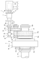
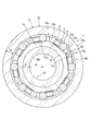
- FIG. 3 is a half cross-sectional view showing the joint member for wind power generator of FIG. 4 is a cross-sectional view taken along arrow A in FIG.
- FIG. 1 is a schematic side view of a wind turbine generator provided with a joint member for wind turbine generator according to an embodiment of the present invention.
- the wind turbine generator 1 is configured to generate power by rotating the input shaft 41 of the generator 4 by the torque from the output shaft 35 of the speed increaser 3.
- the joint member 7 for wind power generators of the embodiment of the present invention is used.
- the wind power generator 1 will be described in detail.
- the wind power generator 1 includes a blade (wind receiving member) 11, a support 12, and a nacelle 13.
- the blade 11 is constituted by a plurality of blades provided at the tip of the main shaft 2 and rotates the main shaft 2 by receiving wind.
- the nacelle 13 generates power by using the main shaft 2, a support mechanism 15 for supporting the main shaft 2, a speed increasing device 3 for increasing the rotation of the main shaft 2, and rotational power increased by the speed increasing device 3.
- Machine 4 etc. The support column 12 supports the nacelle 13 so as to be able to turn horizontally around the vertical axis.
- FIG. 2 is a schematic side view showing the speed increaser 3 and the generator 4.
- the generator 4 is configured by, for example, an induction generator, and an input shaft 41 that rotates using the rotation increased by the speed increaser 3 as an input, and a rotor 42 that is built in the generator 4. And a stator (not shown).
- the rotor 42 is coupled to the input shaft 41 so as to be integrally rotatable, and the generator 4 is configured to generate power when the input shaft 41 rotates and the rotor 42 is driven.
- the input shaft 41 is provided with a brake 44 for braking the input shaft 41.
- the speed increaser 3 includes a gear mechanism (rotation transmission mechanism) 30 that inputs the rotation of the main shaft 2 and accelerates the rotation.
- the gear mechanism 30 includes a planetary gear mechanism 31 and a high-speed gear mechanism 32 that inputs the rotation accelerated by the planetary gear mechanism 31 and further accelerates the rotation.
- the planetary gear mechanism 31 includes an internal gear (ring gear) 31a, a plurality of planetary gears 31b held by a planet carrier (not shown) coupled to the main shaft 2 so as to be integrally rotatable, and a sun gear 31c meshing with the planetary gear 31b. have.
- the sun gear 31 c rotates through the planetary gear 31 b, and the rotation is transmitted to the low speed shaft 33 of the high speed gear mechanism 32.
- the high speed gear mechanism 32 includes a low speed shaft 33 having a low speed gear 33a, an intermediate shaft 34 having a first intermediate gear 34a and a second intermediate gear 34b, and an output shaft 35 having a high speed gear 35a.
- the low speed shaft 33 is a large rotating shaft having a diameter of about 1 m, for example, and is disposed concentrically with the main shaft 2. Both axial ends of the low speed shaft 33 are rotatably supported by roller bearings 36a and 36b.
- the intermediate shaft 34 is disposed in parallel with the low-speed shaft 33, and both axial ends thereof are rotatably supported by roller bearings 37a and 37b.
- the first intermediate gear 34a of the intermediate shaft 34 meshes with the low speed gear 33a, and the second intermediate gear 34b meshes with the high speed gear 35a.
- the output shaft 35 is disposed in parallel with the intermediate shaft 34 and outputs rotational torque.
- One end portion 35b and the other end portion (output end portion) 35c side of the output shaft 35 are rotatably supported by roller bearings 38 and 39, respectively.
- the rotation of the main shaft 2 is made in three stages depending on the gear ratio of the planetary gear mechanism 31, the gear ratio between the low speed gear 33a and the first intermediate gear 34a, and the gear ratio between the second intermediate gear 34b and the high speed gear 35a. And output from the output end 35c of the output shaft 35. That is, the rotation of the main shaft 2 by wind power is increased in three stages by the speed increaser 3 and output from the output shaft 35, and the generator 4 is driven by the rotational torque of the output shaft 35.
- joint member (joint for wind power generator) that enables torque transmission between the output shaft 35 and the input shaft 41.
- the joint member 7 is provided closer to the speed increaser 3 than the brake 44 for the input shaft 41.
- FIG. 3 is a half sectional view showing the joint member 7, and FIG. 4 is a sectional view taken along arrow A in FIG.
- the joint member 7 includes a first rotating body 50, a second rotating body 51, a one-way clutch 52, and a pair of rolling bearings 8 and 9.
- the one-way clutch 52 and the rolling bearings 8 and 9 are disposed between the first rotating body 50 and the second rotating body 51.
- the first rotator 50 is disposed concentrically with the output shaft 35, and a flange 54 is provided at an end 50 a on the output shaft 35 side.
- the flange 54 and the first rotator 50 can be integrally rotated by a key 55. ing.
- a flange 57 fixed to the output shaft 35 with a key 56 is fixed to the flange 54 with a fastener 58 made of bolts and nuts.
- a cover 59 is fixed to the end 50 a of the first rotating body 50 on the output shaft 35 side by a bolt 60, and the end surface of the key 55 is covered by the cover 59.
- the first rotating body 50 is a hollow shaft over the entire length in the axial direction.
- the radial thickness (thickness) T1 of the first rotating body 50 is smaller than the radius R of the inner peripheral surface of the first rotating body 50 and the radial thickness (thickness) T2 of the second rotating body 51.
- the radial thickness T1 is about 20 mm, for example, and the radial thickness T2 is about 30 mm, for example.
- the material of the first rotating body 50 is preferably a material with low rigidity against torsion, for example, S25C which is carbon steel for mechanical structure, titanium, fiber reinforced plastic (FRP) or the like.
- the second rotating body 51 is disposed concentrically with the first rotating body 50.
- the second rotating body 51 includes a cylindrical portion 51a positioned on the radially outer side of the first rotating body 50, and a flange portion 51b extending radially outward from an end portion of the cylindrical portion 51a on the input shaft 41 side.
- the cylindrical portion 51a is made of a cylindrical member, and is in a state of overlapping in the radial direction with respect to the axial center portion of the first rotating body 50 and the portion on the input shaft 41 side from the axial center portion.
- the flange portion 51b is fixed to a flange 62 fixed to the input shaft 41 with a key 61 or the like by a fastener 63 made of bolts and nuts.
- the material of the second rotating body 51 is made of, for example, bearing steel (SUJ2). And the rigidity with respect to the torsion of the first rotating body 50 is configured to be lower than the rigidity with respect to the torsion of the second rotating body 51.
- the one-way clutch 52 is provided between the first rotating body 50 and the second rotating body 51.
- the one-way clutch 52 includes an inner ring 71 and an outer ring 72, a plurality of rollers (engagers) 73 disposed between the outer peripheral surface 71 a of the inner ring 71 and the inner peripheral surface 72 a of the outer ring 72, and the rollers 73.
- An annular retainer 74 that retains the roller 73 at predetermined intervals along the circumferential direction, and a plurality of elastic members 75 that elastically bias each roller 73 toward one circumferential direction (see FIG. 4).
- FIG. 4 In the present embodiment, in FIG.
- the axial center position of the roller 73 in the one-way clutch 52 that is, the axial center position of the connecting portion (engagement portion) constituted by the roller 73, the inner ring 71 and the outer ring 72, It is defined as an arrangement position P1 of the one-way clutch 52.
- the arrangement position P1 of the one-way clutch 52 exists on the input shaft 41 side with respect to the axial center position C of the first rotating body 50. That is, the one-way clutch 52 is not located at the center between the output shaft 35 and the input shaft 41 but is disposed closer to the input shaft 41 side (right side in FIG. 3).
- the inner ring 71 is externally fitted and fixed to a portion of the first rotating body 50 near the input shaft 41 and rotates integrally with the first rotating body 50.
- the region C at the substantially central portion in the axial direction of the cylindrical portion 51 a of the second rotating body 51 has a function as the outer ring 72 of the one-way clutch 52, and the inner peripheral surface of this region C is the inner peripheral surface of the outer ring 72. 72a.
- the rollers 73 have a cylindrical shape, and eight rollers 73 are arranged in the circumferential direction in this embodiment.
- the holder 74 holds these rollers 73 at equal intervals.
- the retainer 74 includes a pair of annular portions 74a facing each other in the axial direction, and a plurality of column portions 74b extending between the annular portions 74a in the axial direction and arranged at equal intervals in the circumferential direction (see FIG. 4). And have. These pillar portions 74b connect both annular portions 74a.
- a pocket 74c is formed between the two annular portions 74a and a pair of column portions 74b adjacent to each other in the circumferential direction, and each roller 73 is individually accommodated in each pocket 74c.
- the elastic member 75 includes a compression coil spring, and is individually accommodated in each pocket 74c of the retainer 74 and attached to the column portion 74b.
- the same number (eight) of flat cam surfaces 71a1 as the rollers 73 are formed on the outer peripheral surface 71a of the inner ring 71, and the inner peripheral surface 72a of the outer ring 72 is a cylindrical surface.
- a plurality (eight) of wedge-shaped spaces S are formed in the circumferential direction.
- the rollers 73 are individually arranged in each wedge-shaped space S, and the elastic member 75 urges the rollers 73 in the direction in which the wedge-shaped space S is narrowed.
- the outer peripheral surface of the roller 73 is a contact surface 73a that contacts the cam surface 71a1 of the inner ring 71 and the inner peripheral surface 72a of the outer ring 72, and the contact surface 73a is formed straight in the width direction (axial direction). .
- the pair of rolling bearings 8 and 9 are disposed on both axial sides of the roller 73 and between the first rotating body 50 and the cylindrical portion 51 a of the second rotating body 51, and the first rotating body 50. And the 2nd rotary body 51 is supported so that relative rotation is mutually possible.
- the rolling bearings 8 and 9 are cylinders provided with inner rings 81 and 91 and outer rings 82 and 92, and a plurality of cylindrical rollers 83 and 93 disposed so as to be able to roll between the inner rings 81 and 91 and the outer rings 82 and 92. Consists of roller bearings.
- the inner rings 81 and 91 are fitted on the first rotating body 50, and inner ring raceway surfaces 81a and 91a are formed on the outer peripheral surface.
- a region B and a region D on both end sides in the axial direction of the cylindrical portion 51a of the second rotating body 51 have a function as the outer rings 82 and 92 of the rolling bearings 8 and 9, and the inner peripheral surfaces of the regions B and D Are the outer ring raceway surfaces 82a, 92a of the outer rings 82, 92.
- Cylindrical rollers 83 and 93 are rotatably arranged between the outer ring raceway surfaces 82a and 92a and the inner ring raceway surfaces 81a and 91a.
- a pair of annular members 85 and 86 are externally fitted and fixed to the outer peripheral surface of the first rotating body 50.
- the annular member 85 on the output shaft 35 side abuts the end of the inner ring 81 of the rolling bearing 8 on the output shaft 35 side in the axial direction, and the annular member 86 on the input shaft 41 side is on the input shaft 41 side of the inner ring 91 of the rolling bearing 9. It is contact
- Seal members 87 and 88 are interposed between the outer peripheral surfaces of the annular members 85 and 86 and the inner peripheral surfaces at both axial ends of the cylindrical portion 51 a of the second rotating body 51.
- a power transmission portion from the output shaft 35 to the one-way clutch 52 in the first rotating body 50 is a torsion promoting portion 50b that easily undergoes torsional elastic deformation. That is, the twist promoting part 50b has a spring function like a torsion bar.
- the torsional elastic deformation is a deformation around the center line of the first rotating body 50.
- a portion of the second rotating body 51 from the end portion 51c on the input shaft 41 side to the corresponding position P3 corresponding to the arrangement position P1 of the one-way clutch 52 and the axial direction (hereinafter, this portion is referred to as a first portion).
- the torsion promoting portion 50b is configured to have lower torsional rigidity than the two-rotor 51 side portion).
- the rigidity to twist is lower in the torsion promoting portion 50b than the second rotating body 51 side portion
- the joint body (joint member 7) including the one-way clutch 52 in a locked state (described later) connected to the two-rotor 51 so as to rotate integrally is torsionally elastically deformed
- the relative displacement amount (twist amount, twist angle) with respect to the direction is larger than the relative displacement amount (twist amount, twist angle) with respect to the circumferential direction in the second rotating body 51 side portion ” Yes.
- the remaining portion 50c other than the torsion promoting portion 50b of the first rotating body 50 that is, the portion from the corresponding position P2 to the end 50d on the input shaft 41 side in the first rotating body 50 is particularly considered for torsional elastic deformation. It becomes a part which does not need to be.
- the twist promoting part 50b will be further described.
- the corresponding position P2 corresponding to the arrangement position P1 of the one-way clutch 52 is used as a boundary, and the output shaft 35 side is made to function as the torsion promoting portion 50b. Since the corresponding position P2 is arranged on the input shaft 41 side with respect to the axial center position C of the first rotating body 50, the axial length L1 of the torsion promoting portion 50b is the same as that of the first rotating body 50.
- the joint main body (joint member 7) including the second rotating body 51 is set to be longer than 1 ⁇ 2 of the axial total length L.
- the axial length of the remaining portion 50c of the first rotating body 50 is L2.
- the wind force increases in the one-way clutch 52, the first rotating body 50 rotates at a higher speed, and the first rotating body.
- the rotational speed of 50 exceeds the rotational speed of the second rotating body 51, the inner ring 71 tends to rotate relative to the outer ring 72 in one direction (counterclockwise direction in FIG. 4).
- the roller 73 slightly moves in the direction in which the wedge-shaped space S is narrowed by the urging force of the elastic member 75, so that the contact surface 73 a of the roller 73 is the outer peripheral surface 71 a of the inner ring 71 and the inner peripheral surface 72 a of the outer ring 72.
- the one-way clutch 52 is in a state where the roller 73 is engaged between the inner and outer rings 71 and 72.
- the inner and outer rings 71 and 72 can be integrally rotated in the one direction, and the first rotating body 50 and the second rotating body 51 can be connected to be integrally rotatable.
- a state in which such integral rotation is connected is referred to as a “locked state”.
- the first rotating body 50 is rotated at an increased speed, the wind force is constant, the first rotating body 50 is rotated at a constant speed, and the rotation speed of the first rotating body 50 is the same as the rotation speed of the second rotating body 51.
- the roller 73 is held in a state where it is engaged between the inner and outer rings 71 and 72 (locked state). Therefore, the one-way clutch 52 maintains the integral rotation of the inner and outer rings 71, 72 in the one direction, and the first rotating body 50 and the second rotating body 51 continue to rotate integrally.
- the first rotating body 50 rotates at a reduced speed, and the rotation speed of the first rotating body 50 is lower than the rotation speed of the second rotating body 51.
- the inner ring 71 tends to rotate relative to the outer ring 72 in the other direction (clockwise direction in FIG. 4).
- the roller 73 slightly moves in the direction in which the wedge-shaped space S widens against the urging force of the elastic member 75, so that the engagement between the roller 73 and the inner and outer rings 71, 72 is released. .
- the engagement between the rollers 3 is released, so that the connection between the first rotating body 50 and the second rotating body 51 is interrupted.
- a state in which this connection is interrupted is called an “unlocked state”.
- the torsion promoting portion 50b provided from the output shaft 35 to the power transmission portion to the one-way clutch 52 undergoes torsional elastic deformation, and the speed increasing device 3 Attenuates the impact torque that is headed. For this reason, it can suppress that a big impact torque acts on the output shaft 35 of the gearbox 3. Therefore, it is possible to suppress a large mechanical stress from acting on the gearbox 3 due to the impact torque and adversely affecting the durability of the gearbox 3. And after the said reconnection, the twist promotion part 50b of the 1st rotary body 50 returns to the original posture by an elastic restoring force.
- the power transmission portion from the output shaft 35 to the one-way clutch 52 in the first rotating body 50 in other words, the impact acting on the speed increaser 3 in the first rotating body 50.
- a portion necessary for torque attenuation is a torsion promoting portion 50b that is easily torsionally elastically deformed.
- the torsion promoting portion 50b is constituted by a hollow shaft portion.
- the twist promoting portion 50b is set to be longer than 1 ⁇ 2 of the overall axial length L of the joint body (joint member 7).
- the torsion promoting portion 50b that is long in the axial direction is obtained. That is, the structure which can absorb the said impact torque easily by the twist in the twist acceleration
- the first rotating body 50 and the second rotating body 51 may be formed of different materials so that the rigidity of the first rotating body 50 with respect to torsion is lower than the rigidity with respect to the torsion of the second rotating body 51.
- the first rotating body 50 may be made of a material whose rigidity against torsion becomes weak, while the material of the second rotating body 51 may be selected with emphasis on material cost, strength, and the like. That is, the rigidity of the first rotating body 50 with respect to the torsion of the material may be smaller than the rigidity of the second rotating body 51 with respect to the torsion of the material.
- the present invention is not limited to the above-described embodiment, and can be implemented with appropriate modifications.
- the second rotating body 51 is arranged on the outer peripheral side of the first rotating body 50.
- the first rotating body 50 is a cylindrical member, and on the inner peripheral side thereof.
- the shaft-like second rotating body 51 may be disposed.
- the first rotator 50 is provided with the twist accelerating portion 50b, and the torsion accelerating portion 50b is configured to have lower rigidity against the twist than the second rotator 51 side portion.
- the wind power generator 1 is not limited to the horizontal axis type shown in FIG. 1, but may be a vertical axis type.
Landscapes
- Engineering & Computer Science (AREA)
- General Engineering & Computer Science (AREA)
- Mechanical Engineering (AREA)
- Life Sciences & Earth Sciences (AREA)
- Sustainable Development (AREA)
- Sustainable Energy (AREA)
- Chemical & Material Sciences (AREA)
- Combustion & Propulsion (AREA)
- Power Engineering (AREA)
- Wind Motors (AREA)
- Vibration Dampers (AREA)
Abstract
Description
また、第1回転体の増速回転後に、風力が一定となって、第1回転体が定速回転となり、第1回転体の回転速度が第2回転体の回転速度と同一になった場合には、第1回転体及び第2回転体は一体回転し続ける。
一方、第1回転体の増速回転後に、風力が低下し、第1回転体が減速回転して、第1回転体の回転速度が第2回転体の回転速度を下回る場合には、第1回転体と第2回転体との接続が遮断される。
この際、本発明の前記第1の態様の構成によれば、第1回転体における、出力軸から一方向クラッチへの動力伝達部分に設けられているねじれ促進部が、ねじれ弾性変形することにより、増速機に向かう衝撃トルクが減衰されるので、増速機に大きな衝撃トルクが作用するのを抑制することができる。したがって、上記衝撃トルクにより、増速機に大きな機械的ストレスが作用して、増速機の耐久性に悪影響を及ぼすことを抑制することが可能となる。
この構成によれば、第1回転体において、増速機に向かう衝撃トルクの減衰に必要な部分を、ねじれに対する剛性の低いねじれ促進部とすることができる。
この構成によれば、軸方向に長いねじれ促進部が得られる。つまり、前記衝撃トルクを、ねじれ促進部におけるねじれにより吸収しやすい構成が得られる。
中空軸は中実軸よりもねじれに対する剛性が低いことから、ねじれ促進部を中空の軸部とすることで、簡単な構成によりねじれ促進部における、ねじれに対する剛性を低下させることが可能となる。
この構成によれば、前記ねじれ促進部を有した第1回転体を含む風力発電装置用継手部材が用いられることで、風力の急変動時に、増速機に大きな機械的ストレスが作用することを抑制することができる。
この風力発電装置1について具体的に説明すると、風力発電装置1は、ブレード(受風部材)11、支柱12、及びナセル13を備えている。ブレード11は、主軸2の先端に設けられた複数枚の羽根により構成され、風を受けることによって主軸2を回転させる。ナセル13は、主軸2と、この主軸2を支持するための支持機構15と、主軸2の回転を増速する増速機3と、増速機3によって増速された回転動力によって発電する発電機4等を備えている。支柱12は、上下方向の軸心回りに水平旋回可能にナセル13を支持している。
遊星歯車機構31は、内歯車(リングギヤ)31aと、主軸2に一体回転可能として連結された遊星キャリア(図示省略)に保持された複数の遊星歯車31bと、遊星歯車31bに噛み合う太陽歯車31cとを有している。これにより、主軸2とともに遊星キャリアが回転すると、遊星歯車31bを介して太陽歯車31cが回転し、その回転が高速段歯車機構32の低速軸33に伝達される。
低速軸33は、その直径が例えば約1mの大型の回転軸からなり、主軸2と同心上に配置されている。低速軸33の軸方向両端部はころ軸受36a,36bにより回転自在に支持されている。
出力軸35は中間軸34と平行に配置されており、回転トルクを出力する。出力軸35の軸方向の一端部35b及び他端部(出力端部)35c側は、それぞれころ軸受38,39により回転自在に支持されている。
第1回転体50は軸方向全長にわたって中空の軸とされている。第1回転体50の径方向厚さ(肉厚)T1は、第1回転体50の内周面の半径R及び第2回転体51の径方向厚さ(肉厚)T2よりも小とされており、径方向厚さT1は例えば20mm程度とされ、径方向厚さT2は例えば30mm程度とされる。また、第1回転体50の素材はねじれに対する剛性が弱くなるものが好ましく、例えば、機械構造用炭素鋼であるS25C、チタン、繊維強化プラスチック(FRP)等とされている。
フランジ部51bは、入力軸41にキー61等により固定されたフランジ62にボルト及びナットから成る締結具63により固定されている。第2回転体51の素材は、例えば、軸受鋼(SUJ2)からなる。
そして、第1回転体50のねじれに対する剛性は、第2回転体51のねじれに対する剛性よりも低くなるように構成されている。
本実施形態では、図3において、一方向クラッチ52における、ころ73の軸方向中央位置、すなわち、ころ73、内輪71及び外輪72により構成される接続部分(噛み合い部分)の軸方向中央位置を、一方向クラッチ52の配置位置P1と定義している。
この一方向クラッチ52の配置位置P1は、第1回転体50の軸方向中央位置Cよりも入力軸41側に存在している。すなわち、一方向クラッチ52は、出力軸35と入力軸41との間の中央ではなく、入力軸41側(図3の右側)寄りに配置されている。
ころ73は円柱形状とされ、本実施形態では周方向に8個配置されている。
弾性部材75は圧縮コイルバネからなり、保持器74の各ポケット74cに個別に収容されて柱部74bに取り付けられている。
転がり軸受8,9は、内輪81,91及び外輪82,92と、内輪81,91と外輪82,92との間に転動可能に配置された複数の円筒ころ83,93とを備えた円筒ころ軸受からなる。
第1回転体50の外周面には一対の環状部材85,86が外嵌し固定されている。出力軸35側の環状部材85は転がり軸受8の内輪81の出力軸35側の端部と軸方向に関して当接し、入力軸41側の環状部材86は転がり軸受9の内輪91の入力軸41側の端部と軸方向に関して当接している。各環状部材85,86の外周面と第2回転体51の円筒部51aにおける軸方向両端部の内周面との間には、シール部材87,88が介装されている。
ここで、「第2回転体51側部分よりも、ねじれ促進部50bにおいて、ねじれに対する剛性が低い」とは、第1回転体50、第2回転体51、及びこれら第1回転体50と第2回転体51とを一体回転可能に接続した(後述の)ロック状態にある一方向クラッチ52を含む継手本体部(継手部材7)をねじり弾性変形させた場合に、「ねじれ促進部50bにおける周方向に関する相対的な変位量(ねじれ量、ねじれ角)が、第2回転体51側部分における周方向に関する相対的な変位量(ねじれ量、ねじれ角)よりも大である」ことを意味している。
なお、第1回転体50のねじれ促進部50b以外の残部50c、すなわち、第1回転体50における上記対応位置P2から入力軸41側の端部50dまでの部分は、ねじれ弾性変形について特に考慮しなくてもよい部分となる。
そして、この対応位置P2が第1回転体50の軸方向中央位置Cよりも入力軸41側に配置されていることで、ねじれ促進部50bの軸方向長さL1は、第1回転体50と第2回転体51とを含む継手本体部(継手部材7)の軸方向全長Lの1/2よりも、長く設定されている。なお、第1回転体50の残部50cの軸方向長さをL2としている。
この場合、弾性部材75の付勢力により、ころ73はくさび状空間Sが狭くなる方向へ僅かに移動して、ころ73の接触面73aが内輪71の外周面71a及び外輪72の内周面72aに圧接し、一方向クラッチ52はころ73が内外輪71,72の間に噛み合った状態となる。これにより、内外輪71,72は前記一方向に一体回転可能となり、第1回転体50と第2回転体51とを一体回転可能に接続することができる。このように一体回転可能に接続されている状態を「ロック状態」と呼ぶ。
一方、第1回転体50の増速回転後に、風力が低下して、第1回転体50が減速回転し、第1回転体50の回転速度が第2回転体51の回転速度を下回る場合には、内輪71が外輪72に対して他方向(図4の時計回り方向)に相対回転しようとする。この場合には、弾性部材75の付勢力に抗して、ころ73はくさび状空間Sが広くなる方向へ僅かに移動することにより、ころ73と内外輪71,72との噛み合いが解除される。このように、ころ3の噛み合いが解除されることで、第1回転体50と第2回転体51との接続が遮断される。この接続が遮断されている状態を「ロック解除状態」と呼ぶ。
この際、本実施形態の第1回転体50では、出力軸35から一方向クラッチ52への動力伝達部分までに設けられている前記ねじれ促進部50bが、ねじれ弾性変形し、増速機3に向かう衝撃トルクを減衰する。このため、増速機3の出力軸35に大きな衝撃トルクが作用することを抑制することができる。したがって、上記衝撃トルクにより、増速機3に大きな機械的ストレスが作用して、増速機3の耐久性に悪影響を及ぼすことを抑制することが可能となる。
そして、上記再接続後には、第1回転体50のねじれ促進部50bが、弾性復元力により、元の体勢に戻る。
また、本実施形態では、前記のとおり、ねじれ促進部50bの軸方向長さL1が、継手本体部(継手部材7)の軸方向全長Lの1/2よりも、長く設定されており、これにより、軸方向に長いねじれ促進部50bが得られる。つまり、前記衝撃トルクを、ねじれ促進部50bにおけるねじれにより、吸収しやすい構成が得られる。
50:第1回転体、 50a:端部、 50b:ねじれ促進部、
50c:残部、 51:第2回転体、 52:一方向クラッチ、
L:軸方向全長、 L1:軸方向長さ、 P1:配置位置、
P2:対応位置、 P3:対応位置
Claims (5)
- 増速機が有する出力軸からのトルクによって発電機が有する入力軸を回転させて発電する風力発電装置に用いられる風力発電装置用継手部材であって、
前記出力軸と一体回転する第1回転体と、
当該第1回転体と同心状に配置されると共に、前記入力軸と一体回転する第2回転体と、
前記第1回転体と前記第2回転体との間に設けられ、前記出力軸の回転速度が前記入力軸の回転速度を上回る状態で前記第1回転体と前記第2回転体とを一体回転可能に接続し、前記出力軸の回転速度が前記入力軸の回転速度を下回る状態で前記第1回転体と前記第2回転体との接続を解除する一方向クラッチと、
を有し、
前記第1回転体における、前記出力軸から前記一方向クラッチへの動力伝達部分に、ねじれ弾性変形し易いねじれ促進部が設けられている、
風力発電装置用継手部材。 - 前記第1回転体における、前記出力軸側の端部から前記一方向クラッチの配置位置と軸方向に関して対応する位置までの部分が、前記ねじれ促進部とされ、
前記第2回転体における、前記入力軸側の端部から前記一方向クラッチの配置位置と軸方向に関して対応する位置までの部分よりも、前記ねじれ促進部において、ねじれに対する剛性が低く構成されている請求項1に記載の風力発電装置用継手部材。 - 前記ねじれ促進部の軸方向長さは、前記第1回転体と前記第2回転体とを含む継手本体部の軸方向全長の1/2よりも、長く設定されている請求項2に記載の風力発電装置用継手部材。
- 前記ねじれ促進部は、中空の軸部により構成されている請求項1~3の何れか一項に記載の風力発電装置用継手部材。
- 風力により回転する主軸と、
前記主軸の回転を増速して出力する出力軸を有する増速機と、
前記出力軸の回転を入力として回転する入力軸を有し当該入力軸の回転により発電を行う発電機と、
前記出力軸と前記入力軸との間に設けられ、当該出力軸と当該入力軸との間でトルク伝達を可能とするための請求項1~4の何れか一項に記載の風力発電装置用継手部材と、
を備える風力発電装置。
Priority Applications (3)
| Application Number | Priority Date | Filing Date | Title |
|---|---|---|---|
| CN201580005867.9A CN105940218B (zh) | 2014-01-30 | 2015-01-22 | 用于风力发电设备的接头部件和风力发电设备 |
| EP15743090.1A EP3101276A4 (en) | 2014-01-30 | 2015-01-22 | Joint member for wind power generation apparatus, and wind power generation apparatus |
| US15/113,552 US10233906B2 (en) | 2014-01-30 | 2015-01-22 | Joint member for wind power generation apparatus, and wind power generation apparatus |
Applications Claiming Priority (2)
| Application Number | Priority Date | Filing Date | Title |
|---|---|---|---|
| JP2014015584A JP6237273B2 (ja) | 2014-01-30 | 2014-01-30 | 風力発電装置用継手部材及び風力発電装置 |
| JP2014-015584 | 2014-01-30 |
Publications (1)
| Publication Number | Publication Date |
|---|---|
| WO2015115286A1 true WO2015115286A1 (ja) | 2015-08-06 |
Family
ID=53756862
Family Applications (1)
| Application Number | Title | Priority Date | Filing Date |
|---|---|---|---|
| PCT/JP2015/051602 Ceased WO2015115286A1 (ja) | 2014-01-30 | 2015-01-22 | 風力発電装置用継手部材及び風力発電装置 |
Country Status (5)
| Country | Link |
|---|---|
| US (1) | US10233906B2 (ja) |
| EP (1) | EP3101276A4 (ja) |
| JP (1) | JP6237273B2 (ja) |
| CN (1) | CN105940218B (ja) |
| WO (1) | WO2015115286A1 (ja) |
Cited By (1)
| Publication number | Priority date | Publication date | Assignee | Title |
|---|---|---|---|---|
| CN112041559A (zh) * | 2018-02-28 | 2020-12-04 | 乌本产权有限公司 | 风能设施的发电机,具有其的风能设施,用于锁定发电机的方法以及锁定设备的应用 |
Families Citing this family (4)
| Publication number | Priority date | Publication date | Assignee | Title |
|---|---|---|---|---|
| JP6191387B2 (ja) | 2013-08-29 | 2017-09-06 | 株式会社ジェイテクト | 継手構造及び風力発電装置 |
| JP2015169143A (ja) * | 2014-03-07 | 2015-09-28 | 株式会社ジェイテクト | 発電装置及びこれに用いる軸継手装置 |
| DE102017008878A1 (de) * | 2017-09-21 | 2019-03-21 | Imo Holding Gmbh | Hauptlagereinheit für die Rotorwelle einer Windkraftanlage und Windkraftanlage |
| CN113394912B (zh) * | 2021-06-02 | 2022-05-10 | 厦门彼奥动力科技有限公司 | 一种用于柴油发电机组的柔性传动系统 |
Citations (5)
| Publication number | Priority date | Publication date | Assignee | Title |
|---|---|---|---|---|
| US6099255A (en) * | 1994-10-17 | 2000-08-08 | Lee; Wai Cheung | Fluid power storage device |
| JP2003056451A (ja) * | 2001-08-20 | 2003-02-26 | Seiko Epson Corp | 風車発電装置 |
| JP2013060825A (ja) | 2011-09-12 | 2013-04-04 | Jtekt Corp | 発電装置 |
| JP2013076395A (ja) * | 2011-09-12 | 2013-04-25 | Jtekt Corp | 発電装置 |
| JP2014015584A (ja) | 2012-07-11 | 2014-01-30 | Sanyo Chem Ind Ltd | 粘度指数向上剤組成物および潤滑油組成物 |
Family Cites Families (19)
| Publication number | Priority date | Publication date | Assignee | Title |
|---|---|---|---|---|
| FR2300259A1 (fr) * | 1975-02-05 | 1976-09-03 | Mecanique Et Metallurg Ste Gle | Perfectionnements aux accouplements elastiques |
| CN2177125Y (zh) | 1993-05-05 | 1994-09-14 | 孔庆堂 | 两端带轴承的桃形楔块式单向超越离合器 |
| DE19961643A1 (de) * | 1999-12-21 | 2001-06-28 | Canders Wolf R | Schwungrad mit Speichern von Rotationsenergie |
| US6583528B2 (en) * | 2000-06-19 | 2003-06-24 | Indigo Energy, Inc. | High performance composite flywheel |
| DE10119427A1 (de) | 2001-04-20 | 2002-10-24 | Enron Wind Gmbh | Kopplungsvorrichtung für eine Windkraftanlage |
| JP4663922B2 (ja) * | 2001-07-23 | 2011-04-06 | 株式会社ジェイテクト | 駆動力伝達装置 |
| EP1647418B1 (en) * | 2004-10-13 | 2012-06-27 | Nsk Ltd. | Hub unit with wheel support and bearing ring, and method of manufacturing the hub unit |
| EP1939479B1 (en) * | 2006-09-28 | 2012-07-11 | JTEKT Corporation | Torque limiter-incorporating one-way clutch |
| DE102008009351A1 (de) * | 2008-02-14 | 2009-08-20 | Innovative Windpower Ag | Vorrichtung zur Drehmomentbegrenzung in einem Triebstrang |
| GB0813173D0 (en) * | 2008-02-21 | 2008-08-27 | Magnomatics Ltd | Wind turbine power train |
| CN101981351B (zh) * | 2008-03-26 | 2014-04-23 | 株式会社捷太格特 | 皮带轮单元 |
| US8257210B2 (en) * | 2008-05-27 | 2012-09-04 | Jtekt Corporation | Rotation urging mechanism and pulley device |
| GB0920148D0 (en) * | 2009-11-17 | 2009-12-30 | Magnomatics Ltd | Magnetically geared machine for marine generation |
| IT1397081B1 (it) * | 2009-11-23 | 2012-12-28 | Rolic Invest Sarl | Impianto eolico per la generazione di energia elettrica |
| US8932017B2 (en) | 2010-08-18 | 2015-01-13 | Ebo Group, Inc. | Wind turbine torque limiting clutch system |
| US9097239B2 (en) | 2010-08-18 | 2015-08-04 | Ebo Group, Inc. | Wind turbine torque limiting clutch system |
| JP5397411B2 (ja) * | 2011-05-17 | 2014-01-22 | 株式会社日本自動車部品総合研究所 | 流体ブレーキ装置及びバルブタイミング調整装置 |
| US9035476B2 (en) | 2011-09-12 | 2015-05-19 | Jtekt Corporation | Power generating device |
| ES2675291T3 (es) * | 2012-04-24 | 2018-07-10 | Ebo Group, Inc. | Sistema de embrague limitador de par para uso en turbinas eólicas |
-
2014
- 2014-01-30 JP JP2014015584A patent/JP6237273B2/ja not_active Expired - Fee Related
-
2015
- 2015-01-22 US US15/113,552 patent/US10233906B2/en not_active Expired - Fee Related
- 2015-01-22 EP EP15743090.1A patent/EP3101276A4/en not_active Withdrawn
- 2015-01-22 CN CN201580005867.9A patent/CN105940218B/zh not_active Expired - Fee Related
- 2015-01-22 WO PCT/JP2015/051602 patent/WO2015115286A1/ja not_active Ceased
Patent Citations (5)
| Publication number | Priority date | Publication date | Assignee | Title |
|---|---|---|---|---|
| US6099255A (en) * | 1994-10-17 | 2000-08-08 | Lee; Wai Cheung | Fluid power storage device |
| JP2003056451A (ja) * | 2001-08-20 | 2003-02-26 | Seiko Epson Corp | 風車発電装置 |
| JP2013060825A (ja) | 2011-09-12 | 2013-04-04 | Jtekt Corp | 発電装置 |
| JP2013076395A (ja) * | 2011-09-12 | 2013-04-25 | Jtekt Corp | 発電装置 |
| JP2014015584A (ja) | 2012-07-11 | 2014-01-30 | Sanyo Chem Ind Ltd | 粘度指数向上剤組成物および潤滑油組成物 |
Cited By (1)
| Publication number | Priority date | Publication date | Assignee | Title |
|---|---|---|---|---|
| CN112041559A (zh) * | 2018-02-28 | 2020-12-04 | 乌本产权有限公司 | 风能设施的发电机,具有其的风能设施,用于锁定发电机的方法以及锁定设备的应用 |
Also Published As
| Publication number | Publication date |
|---|---|
| US20170009748A1 (en) | 2017-01-12 |
| US10233906B2 (en) | 2019-03-19 |
| EP3101276A1 (en) | 2016-12-07 |
| JP2015140780A (ja) | 2015-08-03 |
| CN105940218B (zh) | 2019-05-31 |
| JP6237273B2 (ja) | 2017-11-29 |
| CN105940218A (zh) | 2016-09-14 |
| EP3101276A4 (en) | 2017-10-04 |
Similar Documents
| Publication | Publication Date | Title |
|---|---|---|
| JP6237273B2 (ja) | 風力発電装置用継手部材及び風力発電装置 | |
| JP6065505B2 (ja) | 発電装置 | |
| JP6380424B2 (ja) | 遊星歯車装置 | |
| KR101748177B1 (ko) | 복합 롤링 베어링부착 파동기어장치 | |
| JP2008196702A (ja) | プラネット・キャリアを有するギア・トランスミッション・ユニット | |
| JP2007525623A (ja) | 遊星歯車装置を備える歯車伝動装置 | |
| JP2013231448A (ja) | 一方向クラッチ及び発電装置 | |
| JP5520247B2 (ja) | 風力発電設備の減速装置及び出力ピニオンを備えた減速装置 | |
| US11215264B2 (en) | Roller gear cam mechanism | |
| WO2015133383A1 (ja) | 発電装置及びこれに用いる軸継手装置 | |
| JP2011102623A (ja) | 遊星ローラ機構 | |
| WO2015098925A1 (ja) | 分割型保持器、一方向クラッチ及び発電装置用の継手 | |
| JP2013053713A (ja) | ころ軸受及び風力発電用増速機 | |
| US20140086744A1 (en) | Torque limiter, wind turbine and wind turbine generator | |
| JP6097045B2 (ja) | トラクションドライブ機構 | |
| US10077762B2 (en) | Power generation device and rotating portion support structure | |
| JP5310667B2 (ja) | トラクションドライブ機構 | |
| JP6090502B2 (ja) | 一方向クラッチ及び発電装置 | |
| JP2013072526A (ja) | ロックドトレーン機構を備えた風力発電用の増速機 | |
| JP2017053378A (ja) | 伝動装置及び差動装置 | |
| JP2011102624A (ja) | 遊星ローラ機構 | |
| JP2008151298A (ja) | 遊星ローラ機構 | |
| JP2015214991A (ja) | 無段変速機 | |
| JP2013053712A (ja) | ころ軸受及び風力発電用増速機 | |
| WO2015019998A1 (ja) | 風力発電装置及びこれに用いる回転伝達装置 |
Legal Events
| Date | Code | Title | Description |
|---|---|---|---|
| 121 | Ep: the epo has been informed by wipo that ep was designated in this application |
Ref document number: 15743090 Country of ref document: EP Kind code of ref document: A1 |
|
| WWE | Wipo information: entry into national phase |
Ref document number: 15113552 Country of ref document: US |
|
| REEP | Request for entry into the european phase |
Ref document number: 2015743090 Country of ref document: EP |
|
| WWE | Wipo information: entry into national phase |
Ref document number: 2015743090 Country of ref document: EP |
|
| NENP | Non-entry into the national phase |
Ref country code: DE |
|
| 121 | Ep: the epo has been informed by wipo that ep was designated in this application |
Ref document number: 15743090 Country of ref document: EP Kind code of ref document: A1 |