WO2015115301A1 - Dispositif de couplage de faisceaux et procédé de récupération de sortie pour dispositif de couplage de faisceaux - Google Patents
Dispositif de couplage de faisceaux et procédé de récupération de sortie pour dispositif de couplage de faisceaux Download PDFInfo
- Publication number
- WO2015115301A1 WO2015115301A1 PCT/JP2015/051663 JP2015051663W WO2015115301A1 WO 2015115301 A1 WO2015115301 A1 WO 2015115301A1 JP 2015051663 W JP2015051663 W JP 2015051663W WO 2015115301 A1 WO2015115301 A1 WO 2015115301A1
- Authority
- WO
- WIPO (PCT)
- Prior art keywords
- light source
- beam combining
- light sources
- package
- optical system
- Prior art date
- Legal status (The legal status is an assumption and is not a legal conclusion. Google has not performed a legal analysis and makes no representation as to the accuracy of the status listed.)
- Ceased
Links
Images


Classifications
-
- H—ELECTRICITY
- H01—ELECTRIC ELEMENTS
- H01S—DEVICES USING THE PROCESS OF LIGHT AMPLIFICATION BY STIMULATED EMISSION OF RADIATION [LASER] TO AMPLIFY OR GENERATE LIGHT; DEVICES USING STIMULATED EMISSION OF ELECTROMAGNETIC RADIATION IN WAVE RANGES OTHER THAN OPTICAL
- H01S5/00—Semiconductor lasers
- H01S5/40—Arrangement of two or more semiconductor lasers, not provided for in groups H01S5/02 - H01S5/30
- H01S5/4012—Beam combining, e.g. by the use of fibres, gratings, polarisers, prisms
-
- B—PERFORMING OPERATIONS; TRANSPORTING
- B23—MACHINE TOOLS; METAL-WORKING NOT OTHERWISE PROVIDED FOR
- B23K—SOLDERING OR UNSOLDERING; WELDING; CLADDING OR PLATING BY SOLDERING OR WELDING; CUTTING BY APPLYING HEAT LOCALLY, e.g. FLAME CUTTING; WORKING BY LASER BEAM
- B23K26/00—Working by laser beam, e.g. welding, cutting or boring
- B23K26/02—Positioning or observing the workpiece, e.g. with respect to the point of impact; Aligning, aiming or focusing the laser beam
- B23K26/06—Shaping the laser beam, e.g. by masks or multi-focusing
- B23K26/0604—Shaping the laser beam, e.g. by masks or multi-focusing by a combination of beams
- B23K26/0613—Shaping the laser beam, e.g. by masks or multi-focusing by a combination of beams having a common axis
-
- B—PERFORMING OPERATIONS; TRANSPORTING
- B23—MACHINE TOOLS; METAL-WORKING NOT OTHERWISE PROVIDED FOR
- B23K—SOLDERING OR UNSOLDERING; WELDING; CLADDING OR PLATING BY SOLDERING OR WELDING; CUTTING BY APPLYING HEAT LOCALLY, e.g. FLAME CUTTING; WORKING BY LASER BEAM
- B23K26/00—Working by laser beam, e.g. welding, cutting or boring
- B23K26/70—Auxiliary operations or equipment
- B23K26/702—Auxiliary equipment
- B23K26/705—Beam measuring devices
-
- C—CHEMISTRY; METALLURGY
- C03—GLASS; MINERAL OR SLAG WOOL
- C03B—MANUFACTURE, SHAPING, OR SUPPLEMENTARY PROCESSES
- C03B23/00—Re-forming shaped glass
- C03B23/20—Uniting glass pieces by fusing without substantial reshaping
-
- H—ELECTRICITY
- H01—ELECTRIC ELEMENTS
- H01S—DEVICES USING THE PROCESS OF LIGHT AMPLIFICATION BY STIMULATED EMISSION OF RADIATION [LASER] TO AMPLIFY OR GENERATE LIGHT; DEVICES USING STIMULATED EMISSION OF ELECTROMAGNETIC RADIATION IN WAVE RANGES OTHER THAN OPTICAL
- H01S3/00—Lasers, i.e. devices using stimulated emission of electromagnetic radiation in the infrared, visible or ultraviolet wave range
- H01S3/05—Construction or shape of optical resonators; Accommodation of active medium therein; Shape of active medium
- H01S3/08—Construction or shape of optical resonators or components thereof
- H01S3/08059—Constructional details of the reflector, e.g. shape
-
- H—ELECTRICITY
- H01—ELECTRIC ELEMENTS
- H01S—DEVICES USING THE PROCESS OF LIGHT AMPLIFICATION BY STIMULATED EMISSION OF RADIATION [LASER] TO AMPLIFY OR GENERATE LIGHT; DEVICES USING STIMULATED EMISSION OF ELECTROMAGNETIC RADIATION IN WAVE RANGES OTHER THAN OPTICAL
- H01S5/00—Semiconductor lasers
- H01S5/06—Arrangements for controlling the laser output parameters, e.g. by operating on the active medium
- H01S5/068—Stabilisation of laser output parameters
- H01S5/06825—Protecting the laser, e.g. during switch-on/off, detection of malfunctioning or degradation
-
- H—ELECTRICITY
- H01—ELECTRIC ELEMENTS
- H01S—DEVICES USING THE PROCESS OF LIGHT AMPLIFICATION BY STIMULATED EMISSION OF RADIATION [LASER] TO AMPLIFY OR GENERATE LIGHT; DEVICES USING STIMULATED EMISSION OF ELECTROMAGNETIC RADIATION IN WAVE RANGES OTHER THAN OPTICAL
- H01S5/00—Semiconductor lasers
- H01S5/06—Arrangements for controlling the laser output parameters, e.g. by operating on the active medium
- H01S5/068—Stabilisation of laser output parameters
- H01S5/0683—Stabilisation of laser output parameters by monitoring the optical output parameters
-
- H—ELECTRICITY
- H01—ELECTRIC ELEMENTS
- H01S—DEVICES USING THE PROCESS OF LIGHT AMPLIFICATION BY STIMULATED EMISSION OF RADIATION [LASER] TO AMPLIFY OR GENERATE LIGHT; DEVICES USING STIMULATED EMISSION OF ELECTROMAGNETIC RADIATION IN WAVE RANGES OTHER THAN OPTICAL
- H01S5/00—Semiconductor lasers
- H01S5/10—Construction or shape of the optical resonator, e.g. extended or external cavity, coupled cavities, bent-guide, varying width, thickness or composition of the active region
- H01S5/14—External cavity lasers
- H01S5/141—External cavity lasers using a wavelength selective device, e.g. a grating or etalon
- H01S5/143—Littman-Metcalf configuration, e.g. laser - grating - mirror
-
- H—ELECTRICITY
- H01—ELECTRIC ELEMENTS
- H01S—DEVICES USING THE PROCESS OF LIGHT AMPLIFICATION BY STIMULATED EMISSION OF RADIATION [LASER] TO AMPLIFY OR GENERATE LIGHT; DEVICES USING STIMULATED EMISSION OF ELECTROMAGNETIC RADIATION IN WAVE RANGES OTHER THAN OPTICAL
- H01S5/00—Semiconductor lasers
- H01S5/40—Arrangement of two or more semiconductor lasers, not provided for in groups H01S5/02 - H01S5/30
- H01S5/4025—Array arrangements, e.g. constituted by discrete laser diodes or laser bar
- H01S5/4031—Edge-emitting structures
- H01S5/4062—Edge-emitting structures with an external cavity or using internal filters, e.g. Talbot filters
-
- H—ELECTRICITY
- H01—ELECTRIC ELEMENTS
- H01S—DEVICES USING THE PROCESS OF LIGHT AMPLIFICATION BY STIMULATED EMISSION OF RADIATION [LASER] TO AMPLIFY OR GENERATE LIGHT; DEVICES USING STIMULATED EMISSION OF ELECTROMAGNETIC RADIATION IN WAVE RANGES OTHER THAN OPTICAL
- H01S5/00—Semiconductor lasers
- H01S5/40—Arrangement of two or more semiconductor lasers, not provided for in groups H01S5/02 - H01S5/30
- H01S5/4025—Array arrangements, e.g. constituted by discrete laser diodes or laser bar
- H01S5/4087—Array arrangements, e.g. constituted by discrete laser diodes or laser bar emitting more than one wavelength
-
- H—ELECTRICITY
- H01—ELECTRIC ELEMENTS
- H01S—DEVICES USING THE PROCESS OF LIGHT AMPLIFICATION BY STIMULATED EMISSION OF RADIATION [LASER] TO AMPLIFY OR GENERATE LIGHT; DEVICES USING STIMULATED EMISSION OF ELECTROMAGNETIC RADIATION IN WAVE RANGES OTHER THAN OPTICAL
- H01S5/00—Semiconductor lasers
- H01S5/40—Arrangement of two or more semiconductor lasers, not provided for in groups H01S5/02 - H01S5/30
- H01S5/4025—Array arrangements, e.g. constituted by discrete laser diodes or laser bar
Definitions
- the present invention relates to a beam combiner that uses a plurality of laser beams in a single light beam, and an output recovery method of the beam combiner, and particularly to redundancy using a backup light source (a recovery function in the event of a light source failure).
- an optical fiber is fixed to each of a plurality of laser light emitting units, and these optical fibers are bundled to form a handle portion of the optical fiber.
- the laser beam has a configuration for combining a plurality of laser beams.
- the present invention has been made in order to solve the above-described problems, and it is possible to add a spare light source without reducing the upper limit of the laser output by combining a plurality of laser beams with a flexible structure.
- the purpose is to obtain a beam combiner.
- the present invention relates to a plurality of light sources, one or a plurality of auxiliary light sources, and a beam combining optical system that outputs a beam from each of the light sources and the auxiliary light source by combining it with a beam combining element.
- a beam that enters the beam combining optical system from a light source is combined after passing through the beam combining element, a monitor unit that monitors the beam from each of the light sources to detect a failure, and a failure of the light source is detected.
- at least a part of each of the light sources, the spare light source and the beam combining optical system is moved by a movable part provided in at least one part of each of the light sources, the spare light source and the beam combining optical system.
- a beam is incident on the beam combining optical system from the auxiliary light source, and the compound is transmitted in the optical path after the beam combining element.
- a beam coupling device or the like and a light source switching unit for coupling the beam from the light source In the beam coupling device or the like and a light source switching unit for coupling the beam from the light source.
- a beam combining device or the like in which a spare light source can be added without lowering the upper limit of laser output by combining a plurality of laser beams with a flexible structure.
- FIG. 4 is a side view of the LD package of FIG. 3. It is a schematic block diagram of the beam combining apparatus by Embodiment 3 of this invention. It is a figure for demonstrating operation
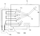
- FIG. 1 is a schematic configuration diagram of a beam combining device according to Embodiment 1 of the present invention.
- a beam combining device 100 including a wavelength-coupled external resonator combines light from a laser diode (LD) element, which is a light source, into one beam by dispersibility and outputs it.
- LD laser diode
- the operation mechanism will be briefly described with reference to FIG.
- a laser beam emitted from the LD package 1a-1e, which is a light source equipped with an LD bar, is provided with a bending mirror 2 provided for each LD package 1a-1e (an optical element that changes the beam direction on the optical path). Then, the direction is changed and the light enters the cylindrical lens 4.
- the laser beam is superimposed on a diffraction grating 5 which is a beam combining element by a cylindrical lens 4, and is superimposed on one beam between the diffraction grating 5 and the partial transmission mirror 6 due to the dispersibility of the diffraction grating 5.
- a housing 7 is provided for housing the LD package 1a-1e, each bending mirror 2, a rail 3, a cylindrical lens 4, a diffraction grating 5, and a partial transmission mirror 6 to be described later.
- An output transmission element 56 having functions of a transmission element and a dispersion optical element is disposed.
- an LD package 1e is a spare light source, which is equivalent to other LD packages.
- a collimating lens CL is provided as necessary (the same applies hereinafter).
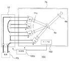
- FIG. 2 shows how the spare LD package 1e operates when the LD package 1b fails in the configuration of FIG.
- the folding mirror 2 placed on the laser beam output side of the LD package 1b is removed or moved out of the optical path of the laser beam of the LD package 1b. Instead, the folding mirror 2 of the spare LD package 1e is moved over the rail 3. It moves and the optical path of the LD package 1b is arranged so that the optical path overlaps.
- the folding mirror 2 is arranged with sufficient arrangement accuracy to function as an alternative to the LD package 1b.
- the rail 3 is offset from the optical path so as not to block the laser beam (for example, offset to the back side of the drawing in the figure).
- the rail 3 may be provided in each of the LD packages 1a-1e, and the folding mirror 2 may be moved to each. Further, the folding mirror 2 of the LD package 1e, the folding mirror 2 of the LD package 1b, and the folding mirrors of other LD packages can be moved manually or electrically, and can be performed from the outside of the housing 7. A mechanism is provided and can move without opening the housing 7. Further, it is desirable to provide a monitor mechanism (monitor unit 102) as shown in FIG. 1 so that the output reduction of the LD package 1a-1e can be monitored individually inside or outside the casing 7 as needed. In FIG. 2 and subsequent figures, illustration of the configuration outside the housing 7 is omitted.
- each LD package 1a-1e is subjected to power supply adjustment and on / off from the power supply circuit.
- Each LD package 1a-1e is provided with a drive motor (not shown) for moving the bending mirror 2 on the rail 3.
- These light source switching functions are shown as a light source switching mechanism 101.
- an LD package state monitor device for detecting a failure of the LD package 1a-1e (the wavelength of the laser beam output from the LD package, the laser beam intensity (output), the emission direction, the voltage at the LD of the LD package, etc. Is shown as the monitor unit 102.
- a control unit 100c including a computer or the like provided outside the housing 7 is connected to the light source switching mechanism 101 and the monitor unit 102, and controls the light source switching mechanism 101 to turn on / off the LD package (specifically, from the power supply circuit).
- the power supply circuit is turned on and off to connect and disconnect the power supply circuit), the power supply is adjusted, and the movement of the bending mirror 2 is controlled according to the input from the operator. Further, the failure LD package is determined according to the state of the LD package monitored by the monitor unit 102.
- the control unit 100c determines the failed LD package from the state of the LD package from the monitor unit 102, controls the light source switching mechanism 101 according to the determination result, disconnects the failed LD package from the power supply circuit, and supplies the spare LD package instead. It may be connected to a circuit, the folding mirror of the failed LD package may be removed from the optical path, and the folding mirror of the spare LD package may be moved so that the optical path is superimposed on the optical path of the failed LD package.
- the operator manually operates an operating rod having one end connected to the folding mirror 2 and the other end penetrating the housing 7 and protruding outside.
- the LD chip may be a single chip.
- the number of LD packages is four when the operation is started and the number of spare LD packages is one, the number of LD packages and spare LD packages is not limited to this. For example, a plurality of spare LD packages may be provided.
- the transmissive diffraction grating 5 is used as a dispersive medium (wavelength-coupled external resonator).
- wavelength-coupled external resonator wavelength-coupled external resonator
- spatial coupling a similar device (beam coupled external resonator) can be configured.
- the light source is coupled to the optical fiber OP (see FIG. 1) on the output side of the beam combiner, even if there is a difference between the light from the LD package 1b and the light from the LD package 1e due to an optical path difference or the like, If it is to some extent, the effect of beam fluctuation caused by switching to the spare LD can be mitigated by the isotropic effect of the beam mode by fiber propagation.
- the light source switching mechanism 101 in FIG. 1 schematically shows a movable portion 1101 for performing the above-described operation and a drive portion 1102 that drives the movable portion 1101.
- the movable unit 1101 is, for example, a mechanism that moves the bending mirror 2 onto the rail 3, and a mechanism that performs adjustment and on / off control of power supply from the power supply circuit to each LD package 1a-1e, for example, as shown in FIG. Including electric switches.
- the drive unit 1102 includes, for example, a drive motor for driving the above-described movable unit, a power supply circuit to the LD package, and a power source for these.
- FIG. FIG. 3 is a schematic configuration diagram of a beam combining device according to Embodiment 2 of the present invention.
- a beam combiner with high redundancy may be configured by providing a movable spare LD package so that the optical path can be switched.
- the laser beams generated from the LD packages 1f, 1g, and 1h are collimated by the cylindrical lens 11 and superimposed on the diffraction grating 5a.
- the beams are superimposed between the diffraction grating 5a and the partial transmission mirror 6a, and different optical paths are formed between the diffraction grating 5a and the LD packages 1f, 1g, and 1h. Due to the dispersibility of the diffraction grating 5a, beams from different LD packages have different wavelengths and are diffracted at different angles, so that the beams are extracted as one beam from the partial transmission mirror 6a.
- FIG. 4 shows a side view of the LD package 1h from the direction of arrow A in FIG.
- the movable mirrors 2a and 2b move when the LD package fails.
- the optical path is launched (the optical path is translated upward) and can be superimposed on the optical path from the LD package 1h to the diffracted photon 5a.
- the LD package 1i and its movable mirrors 2a and 2b are configured to be able to move in the direction of rotation about the diffraction grating 5a as shown by the dotted arrows in FIG.
- the optical paths of the LD packages 1f and 1g can be superimposed.
- the LD package 1i In the beam combiner configured as described above, the LD package 1i, its cylindrical lens 11b, and the movable mirror 2a for launching (optical path translation), regardless of which of the LD packages 1f, 1g, 1h fails, As 2b is rotated and swung up, the optical path of the failed LD package is replaced, and the spare LD package can be started in place of the failed package.
- a control unit 100c, a light source switching mechanism 101, 111, and a monitor unit 102 are provided in the same manner as in the above embodiment, and the LD packages 1f, 1g, It is preferable to determine which one of the 1h has failed and replace the failed LD package with the spare LD package 1i.
- the monitor unit 102 of the failed LD package is a wavelength coupled resonator, it may be equipped with a device for monitoring the wavelength, or an existing wavelength measuring device is used only during monitoring to reduce the cost of the wavelength measuring device.
- a fiber terminal that can be coupled may be provided.
- each LD package may be monitored. Further, when the diffraction grating 5a from which the 0th-order light from the diffraction grating 5a leaks is used, the direction of the leakage light may be monitored to detect which LD package has failed.
- the monitor unit operates automatically, or the monitor unit is provided outside the casing 7a of the apparatus. Further, the mechanism and the wiring for moving the movable unit are switched, and the current flows to the failed LD package. It is desirable that a mechanism for switching so that a current flows in the spare LD package is provided outside the casing of the apparatus, and switching is possible without opening the casing.
- the light source switching mechanism 101 moves the LD package 1i, its cylindrical lens 11b, and the movable mirrors 2a and 2b for launching (optical path parallel movement) in the direction of rotation about the diffraction grating 5a, and is further movable.
- the mirrors 2a and 2b are moved up.
- the LD package 1i, the cylindrical lens 11b, and the movable mirrors 2a and 2b are provided, for example, on a movable support portion (not shown) provided with a drive motor for performing these operations, and the light source switching mechanism 101 has a movable support portion. Control to move.
- the power supply of each LD package is adjusted and turned on / off.
- the monitor unit 102 monitors the state of the LD packages 1f, 1g, and 1h.
- the control unit 100c determines the failed LD package from the monitoring result of the state of the LD package from the monitor unit 102, controls the light source switching mechanism 101 according to the determination result, and disconnects the failed LD package (for example, 1h) from the power supply circuit. Instead, the spare LD package 1i is connected to the power supply circuit, and the LD package 1i, its cylindrical lens 11b, and the movable mirrors 2a and 2b are rotated to the lower side of the failed LD package to move the movable mirrors 2a and 2b up. Make it.
- the detection result of the LD package state from the monitor unit 102 is displayed on the display unit (not shown) of the control unit 100c, and the operator determines the failed LD package from the display, and the failed LD package is made a spare LD package.
- An operator may input a switching instruction to the control unit 100c, and the light source switching mechanism 101 may perform the switching operation according to a control signal from the control unit 100c according to the input instruction.
- a monitor unit 102 is provided outside the housing 7a, and detection from a sensor (not shown) that detects the laser beam wavelength, laser beam intensity (output), emission direction, voltage at the LD of the LD package, and the like in the housing. You may make it receive a signal outside the housing
- the connection and disconnection of the LD package to the power supply circuit are provided outside the housing 7a by providing a wiring switching box for switching the wiring. Alternatively, the wiring switching may be performed by providing an electric switch in the wiring switching box and performing on / off control with a control signal from the control unit 100c. The same applies to the other embodiments.
- the beam combiner configured as described above, since it is possible to replace the failed LD package with a spare LD package when the LD package fails, it is not necessary to open an optical path for the spare LD package in advance. It is possible to generate a larger output. In addition, when replacing, it is possible to detect a faulty part and perform an operation from the outside of the casing, thereby reducing the influence of the fault due to contamination. In addition, the time and labor required for replacement can be reduced.
- the LD packages 1f, 1g, and 1h which are a plurality of light sources, are arranged concentrically around the diffraction grating 5a that is a beam coupling element, for example.
- the LD package 1i which is a preliminary light source, moves on a concentric orbit having a radius smaller than that of the LD packages 1f, 1g, and 1h and offset in a direction perpendicular to a plane including the concentric circles.
- the movable part of the light source switching mechanism 101 is, for example, an LD package 1i, a cylindrical lens 11b, and movable mirrors 2a and 2b that are movably supported as described above. Further, for example, an LD as shown in FIG.
- the drive unit includes an electric switch SW of a mechanism for adjusting power supply from a power supply circuit to the package and performing on / off control.
- the drive unit includes a drive motor that moves these movable units, a power supply circuit to the LD package, and a power source for these.
- FIG. 5 is a schematic configuration diagram of a beam combining device according to Embodiment 3 of the present invention.
- one optical path for a spare light source (spare LD package) is provided in a wavelength-coupled external resonator using dispersibility.
- the optical path can be changed only by switching the wiring from the power source. It is good also as a structure to switch.
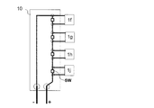
- the LD packages 1f, 1g, and 1h on which the LD bar is mounted are connected in series on the wiring switching box 10 that connects and disconnects the power supply circuit of the LD package.
- a common optical path is provided between the partial transmission mirror 6b and the diffraction grating 5a, and a diffraction angle between the diffraction grating 5a and the LD packages 1f, 1g, and 1h varies depending on the wavelength due to the dispersibility of the diffraction grating 5a.
- An optical path is formed.
- the spare (light source) LD package 1j is connected to the + (positive electrode) terminal and the-(negative electrode) terminal at the start of use in order to prevent failure.
- a cylindrical lens 11c is provided in each of the LD packages 1f, 1g, 1h and the spare (light source) LD package 1j.
- FIG. 6 shows how the spare light source (LD package) 1j substitutes for the operation of the LD package 1g when the LD package 1g fails.
- the spare LD package 1j is configured such that a beam is incident on and superposed on the same position as the other LD in the diffraction grating 5a on which the light from the LD package 1f-1h is incident. Between the part 5a and the partial transmission mirror 6b, it is configured to have the same optical axis as other beams.
- the spare LD package 1j has a gain sufficient to substitute another LD in a wavelength band corresponding to the diffraction angle at the position as shown in FIG.
- the spare LD package 1j is arranged at the end, but it is not necessarily arranged at the end, and it may be arranged between the LD packages or at both ends.
- the number of spare LD packages 1j need not be limited to one, and any number of spare LD packages 1j may be arranged according to the redundancy required for the apparatus.
- operations such as being able to share the optical path from the diffraction grating 5a to the partially transmissive mirror 6b with other LD packages, obtaining a predetermined output, and a predetermined light collecting property are performed in advance before using the apparatus. It has been adjusted.
- the method for detecting a failed LD package may monitor the voltage of each LD package or monitor the laser beam output, emission direction, wavelength, etc. of each LD package. Good. Further, only a terminal for monitoring and a light receiving unit may be provided, and a fiber, a console, and a PC (personal computer) may be connected at the time of inspection.
- the operator stops supplying current to the LD package 1g in the wiring switching box 10 arranged outside the housing 7b as shown in FIG.
- the spare LD package 1j is connected to the power supply circuit, the wiring is switched so that the current supply is started, and the apparatus is operated.
- the output of the LD package may be adjusted by adjusting the current and voltage by the power supply PS shown in FIG.
- the power supply PS can also be used as a power supply for the drive motor of each drive unit.
- the wiring switching box 10 which is a light source switching mechanism is provided outside the casing, and the wiring can be switched without opening the casing. Contamination to elements and LD elements and adverse effects of moisture can be avoided. In addition, since wiring switching and monitoring can be performed quickly, the burden on the operator performing maintenance can be reduced. If possible, it is desirable to automatically perform either or both of detection of a failed LD package and switching of wiring.
- the control unit 100c determines the failed LD package from the monitoring result of the LD package state from the monitor unit 102, and exemplifies FIG. 16 according to the determination result. , Outputs an open / close control signal to the electric switch SW provided on the wiring switching box 10 serving as a light source switching mechanism (including a movable part and a driving part) for connecting and disconnecting the power, and feeds the failed LD package. Disconnect from the circuit and connect the spare LD package 1j to the power supply circuit instead. Furthermore, the current and voltage may be adjusted by controlling the power supply PS of the power feeding circuit.
- the LD package 1f-1h and the spare LD package 1j are connected in series, and a short circuit including the electric switch SW is provided in each LD package.
- the electric switch SW of the short circuit of the spare LD package 1j is turned on (connected and energized), and the electric switch SW of the short circuit of the LD packages 1f, 1g, and 1h. Is off (not connected and cannot be energized), the LD packages 1f, 1g, and 1h operate, and the device performs its function. For example, when the LD package 1g as shown in FIG.
- the short-circuit electric switch SW provided in the LD package 1g changes from the OFF state to the ON state, and the short-circuit electric switch provided in the spare LD package 1j.
- the SW changes from the on state to the off state
- the LD packages 1f and 1h and the spare LD package 1j operate.
- the configuration of the switching circuit is an example, and an appropriate configuration may be used in accordance with the application.
- the wiring switching box 10 may be provided outside the housing, and a mechanism for manually switching may be provided. That is, the effect of the present invention is more greatly exhibited when the current supplied to the light source exceeds 1 A.
- a separate optical path is provided in the spare package to configure the wavelength coupled external oscillator, so that the failure can be achieved only by switching the wiring without providing a moving mechanism or the like as in the second embodiment.
- FIG. 7 is a schematic configuration diagram of a beam combining device according to Embodiment 4 of the present invention.
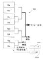
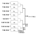
- laser modules 12a to 12h are wavelength-coupled external resonators each including the spare LD package described in the third embodiment, for example.
- 5 includes, for example, the LD package 1f-1h, the spare LD package 1j, the cylindrical lens 11c, the diffraction grating 5a, the partial transmission mirror 6b, the housing 7b, and the wiring switching box 10, the monitor unit 102, and the control unit 100c.
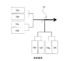
- adjacent laser modules that is, 12a and 12b, 12c and 12d, 12e and 12f, and 12g and 12h, are spatially coupled (position coupled), and a total of eight outgoing beams from each module. Will be four.
- the laser beams generated from the laser modules 12 a and 12 b are collected by the first cylindrical lens 13. Then, it is collimated by the second cylindrical lens 14 disposed after passing through the condensing point, and the interval is narrower than when entering the first cylindrical lens 13. In the laser beam thus narrowed, the light condensing property as a whole of the two beams that are spatially coupled (position coupled) is improved as compared to immediately after they are emitted from the laser modules 12a and 12b.
- the fiber diameter and fiber NA (Numerical Aperture) are selected appropriately, the size and divergence angle that can be incident on the fiber can be accommodated, and the beam can be substantially combined. I can say that.
- the method shown in FIG. 8 is an example, and various other optical systems are conceivable.
- the number of beams that are spatially coupled (position coupled) depends on the condensing property of the beam emitted from the laser module and can be incident on the fiber. If the light property can be maintained, the number may be increased.
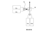
- the spatially-coupled (position-coupled) beams are polarization-coupled to form a total of two beams.
- the polarization coupling will be described with reference to FIG.
- the polarization direction of the laser beams generated from the laser modules 12a and 12b is rotated by 90 degrees as shown in FIG. 9 by a polarization rotation element 15 such as a wave plate or a polarization rotator.
- the polarization direction of the beams generated from the laser modules 12a and 12b is 90 degrees different from the polarization direction of the beams generated from the laser modules 12c and 12d, and is superimposed on one beam by the polarizing element 16. .
- wavelength coupling As shown in FIG. Wavelength coupling will be described with reference to FIG.
- the beams from the laser modules 12 a to 12 d and the beams from the laser modules 12 e to 12 h are combined by the wavelength coupling mirror 17 to be combined into one beam.
- the laser modules 12a-12d and the laser modules 12e-12h need to use laser diodes having different wavelengths.
- the number of wavelength-coupled beams is not limited to two, and may be three or more. For this purpose, it is necessary to prepare laser diodes having different specifications.
- LD LD
- one laser module it is not always the case that one LD package (LD) fails in one laser module as shown in FIGS. 5 and 6, but one laser module. It is possible that two or more LD packages will fail. In addition, a failure may occur due to disconnection, contamination, or the like, and one laser module may not operate at a time (all LD packages in one laser module are in a state of failure or incapable of outputting a beam).
- FIG. 11 is a diagram showing the operation of the beam combining device of the present invention when the laser module 12e becomes inoperable.
- the laser module 12e stops operating.
- the decrease in output due to the stop of the laser module 12e is compensated, the operation is continued, and the operation until the maintenance is continued. Therefore, each laser module may be provided with a plurality of spare LD packages, or there may be a laser module without any spare LD package.
- the operation may be continued by increasing the current in addition to the operation of the spare LD package.
- two or more LD packages fail in one laser module and it is sufficient to operate a part of the spare LD packages, it is not necessary to operate all the spare LD packages.
- the operation may be continued only by moving the LD package.
- each laser module including one spare LD package can be reduced when the number of LD packages included in one laser module exceeds the number of beam combinations after emission from the laser module.
- the only way to increase the number of beam couplings is to increase the number of spatial coupling (position coupling) or wavelength coupling.
- Increasing the number of spatially coupled (positionally coupled) beams degrades the beam condensing performance of the entire device.
- To increase the number of wavelength couplings it is necessary to increase the wavelength, which leads to an increase in cost and difficulty in maintenance.
- the number of beam combinations after emission from the laser module is limited, and it is advantageous to increase the number of wavelength couplings using a diffraction grating or a dispersion optical element, which is a beam combining element in the module, in order to improve the output.
- a wavelength coupling device using a dispersive optical element the effect of the present invention is exhibited more greatly.
- the apparatus can be configured with a smaller number of parts and the probability of failure can be reduced. Moreover, the apparatus can be miniaturized.
- the possibility of dealing with various failures will be expanded.
- one spare laser module when one spare laser module is provided, it is possible that the spare laser module fails and normal operation cannot be performed.
- the output reduction of one laser module can be reduced by another. If it is configured so as to be supplemented with a laser module, it is possible to cover even when one laser module is broken.
- the number of LD packages required to ensure the redundancy can be reduced.
- the monitoring results from the respective monitor units 102 of all the laser modules in the beam combiner are input in a concentrated manner.
- Laser module 102a that monitors a state for detecting a defect (failure) of each LD package in the laser module and the laser module, and a failure laser based on a monitoring result of the state of the laser module and LD package from laser monitor unit 102a
- Control for determining a module and a failed LD package and outputting an open / close control signal for performing open / close control of an electric switch (not shown) provided on the wiring switching box 10 according to the determination result to the controller 100c of the corresponding laser module, for example.
- a laser control unit 100cc for sending a signal may be provided.
- the laser control unit 100cc performs control for causing the control unit 100c of the corresponding laser module to perform control for increasing the output of the normal LD package in order to compensate for the output of the failed LD package.
- the control unit 100c may perform control to increase the LD current of the LD package.
- each laser module is not limited to the configuration of the third embodiment, and may have a configuration including a spare LD package described in other embodiments.
- FIG. 12 is a schematic configuration diagram of a beam combining device according to Embodiment 5 of the present invention.
- the beam combining device of FIG. 12 includes wavelength-coupled external resonators having dispersibility in a plurality of laser modules, which perform coupling by space (position), polarization, and wavelength. A laser beam combined into one beam.
- the laser modules 12f and 12g are not provided with a spare LD package.
- FIG. 13 illustrates a laser module that does not include a spare LD package.
- FIG. 14 shows a wiring change when one of the LD packages shown in FIG. 13 fails.
- no spare LD package is provided in the laser module.
- the wiring switching box 10 is provided so that the wiring can be switched outside the housing 7b so that the LD package can be short-circuited regardless of which LD package is defective. Same as 5 and 6.
- the positive and negative terminals of the failed LD package 1f are short-circuited by wiring, and the operation is stopped.
- the LD package 1f stops operating, the output of the entire laser module is reduced.
- the above wiring is equivalent to the LD package 1f being disconnected from the power supply circuit.
- the LD package 1f may be wired so as to be disconnected from the power feeding circuit.
- the LD package stops operating as shown in FIG. 12, not only the same laser module but also spare laser modules arranged inside other laser modules also operate. It is not necessary to provide an LD package, and the operation can be continued until maintenance is performed. Further, the number of spare LD packages is not necessarily limited to one per module, and may be increased as necessary. Even if the number of spare LD packages is equal to one laser module, the optical element and the housing can be omitted. In such a configuration, since the number of parts is small, the apparatus can be miniaturized. In addition, the probability of failure occurrence can be reduced.
- Embodiment 6 FIG.
- the operating current value of the LD of the LD package is, for example, a device whose limit is 60A and the output increases depending on the current in a current region of 60A or less, it is always operated at 40A or 50A.
- the LD package fails, only the failed LD package is disconnected from the power supply circuit by switching the wiring, the current value is increased to, for example, 55 A, etc., the necessary output is secured, and the operation is continued until maintenance can be performed. Also good.
- the apparatus can be reduced in size.
- FIG. FIG. 15 is a schematic configuration diagram of a beam combining device according to Embodiment 7 of the present invention.
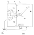
- the LD package 1i, 1j, 1k in which failure may occur the casing 18 in which optical components such as the cylindrical lens 11c around the LD package are arranged, the diffraction grating 5b, and the part
- the housing 7c including other optical elements such as the transmission mirror 6c may be provided separately. In this case, the adjustment is performed while arranging the LD packages one by one, and finally, all the LD packages are not arranged so as to operate normally.
- a positioning member 19 that provides positional accuracy such as an abutment surface and a pin may be provided, and the housing 7c and the housing 18 may be arranged with a positional accuracy higher than a predetermined accuracy.
- the housing 18 and the housing 7c may be configured such that a window W is provided and the inside of the housing 18 and the housing 7c is not affected by contamination or moisture even if it is removed on site. Further, the cover may be applied only when the window is removed so that the window does not affect the normal operation.
- the housing 18 may be adjusted at another place by preparing another housing 7c as a reference for adjusting the housing 18.
- the monitor unit 102 and the control unit 100c are provided, but these devices may be provided on the housing 7c side as shown in FIG. It may be provided separately.
- the LD package can be easily replaced by separating the LD package and the optical component casing.
- an adjustment mechanism for finely adjusting the positional relationship between the housing 18 and the housing 7c may be provided.
- an adjustment mechanism may be provided in part or all of the diffraction grating 5b, the partial reflection mirror 6c, and the like of the components constituting the housing 7c, and adjustment control may be performed from the control unit 100c.
- the adjusting mechanism be a mechanism that can be finely moved without opening the housing.
- all the LD packages are stored in one casing 18, but as shown by a broken line, one part is put in another casing and only a part of the LD package casings is replaced. You may do it.
- another casing 18 may be prepared as a replacement part, and only the casing 18 may be replaced when a failure occurs.
- a spare LD package may be included in the LD packages 1i, 1j, and 1k.
- FIG. 17 is a schematic configuration diagram of a beam combining device according to an eighth embodiment of the present invention.
- a switching configuration between a failed LD package (light source) and a spare LD package (backup light source) is shown in relation to the first embodiment.
- the LD package 1e is a spare light source
- the LD packages 1a, 1b, and 1c are a plurality of light sources.
- an LD package 1a, 1b, 1c, a bending mirror 2A-2F, a cylindrical lens 4, a dispersion optical element 5c as a beam coupling element, and an output coupling element 6d as an output optical element constitute an external resonator.
- the light emitted from the LD packages 1a, 1b, and 1c is coupled to one beam between the output coupling element 6d and the dispersion optical element 5c, and is extracted from the output coupling element 6d. Further, part of the beam incident on the output coupling element 6d is returned to the LD packages 1a, 1b, and 1c via the dispersion optical element 5c.
- part of the light from the LD packages 1a, 1b, and 1c is incident on the monitor unit 102, and can be detected when the output is reduced, for example, by comparison with the intensity of the output signal at the normal time. Yes.
- control unit 100c operates the light source switching mechanism 101 according to the failure location in accordance with the detection result of the failure location of the LD packages 1a, 1b, and 1c from the monitor unit 102, and the failed LD package and the dispersion optical element 5c.
- the optical path connecting the spare LD package 1e and the dispersion optical element 5c is in the operating state.
- the spare LD package 1e can replace the operation of the LD package 1a by moving the folding mirrors 2A, 2E, and 2F.
- the spare LD package 1e can replace the operation of the LD package 1b by moving the folding mirrors 2B and 2F as shown in FIG.
- the spare LD package 1e can replace the operation of the LD package 1c by moving the folding mirror 2C.
- FIG. 21 shows a folding mirror that moves and a folding mirror that remains stationary with respect to failure of each LD package.
- the distance between the spare LD package 1e and the dispersion optical element 5c and the distance between the LD packages 1a, 1b, 1c and the dispersion optical element 5c may be equal.
- a lens illustrated by a broken line in FIG. 17
- a circuit for switching the circuit of the failed LD package from the power supply circuit and switching the power supply to the spare LD package 1 e may be provided.
- the method of removing the folding mirror from the optical path is not limited to movement as long as the optical path is not affected by the bending mirror, and is not limited to movement, but is rotated (indicated by a broken line in the folding mirror 2A in FIG. 17), or moved and rotated. The same effect can be obtained even by applying the combination.
- the bending mirrors 2A to 2F are configured to move on the rails 3a and 3b and to rotate about, for example, the center of the bending mirror by a drive motor (not shown). Further, the LD packages 1a, 1b, 1c and the spare LD package 1e are provided on the moving substrate 112 shown in FIG. 17 so as to be movable in the xy plane by a drive motor (not shown), thereby changing the positions of the LD packages. Thus, it becomes possible to support the failed LD package by the spare LD package.
- LD package 1a-1d is a light source
- LD package 1e is a spare light source
- the diffraction grating 5 is a beam coupling element
- the bending mirror 2, the cylindrical lens 4, the diffraction grating 5, and the partial transmission mirror 6 include a beam coupling optical system
- the monitor unit 102 is a monitor unit
- the light source switching mechanisms 101 and 111 and the control unit 100c are power supply switching units, Configure.
- a mechanism for moving the bending mirror 2 onto the rail 3 and further an electric switch SW of a mechanism for adjusting the power supply from the power supply circuit to each LD package 1a-1e and controlling on / off as shown in FIG. And the like constitute a movable part of the light source switching mechanism 101.
- a drive motor for driving the movable part, a power supply circuit to the LD package, and a power source thereof constitute a drive part of the light source switching mechanism 101.
- LD packages 1f, 1g, 1h are light sources
- LD package 1i is a spare light source
- the diffraction grating 5a is a beam coupling element
- the cylindrical lens 11, the movable mirrors 2a and 2b, the diffraction grating 5a, and the partial transmission mirror 6a are a beam coupling optical system
- the monitor unit 102 is a monitor unit
- the light source switching mechanism 101 and the control unit 100c are a power source switching unit, Configure.
- the LD package 1i, the cylindrical lens 11b, and the movable mirrors 2a and 2b are movably supported by a movable support portion, and further, for example, as shown in FIG.
- An electric switch SW or the like of a mechanism that performs control constitutes a movable part of the light source switching mechanism 101.
- a drive motor that moves these movable parts, a power supply circuit to the LD package, and a power source thereof constitute a drive part of the light source switching mechanism 101.
- LD packages 1f, 1g, 1h are light sources
- LD package 1j is a spare light source
- the diffraction grating 5a is a beam coupling element
- the cylindrical lens 11c, the diffraction grating 5a, and the partial transmission mirror 6b are a beam coupling optical system
- the monitor unit 102 is a monitor unit
- the wiring switching box 10 is a wiring switching box
- the housing 7b is a housing
- the control unit 100c (light source switching mechanism 101) is a power switching unit, Configure.
- the movable switch of the light source switching mechanism 101 is configured by the electric switch SW of the mechanism for adjusting the power supply from the power supply circuit to the LD package and controlling on / off as shown in FIG. To do.
- the power supply circuit to the LD package, its power supply, and the like constitute a drive unit of the light source switching mechanism 101.
- Laser modules 12a-12h are laser modules
- the spatial coupling (position coupling) unit, the polarization coupling unit, the wavelength coupling unit, and the fiber coupling unit are a module beam coupling optical system 500
- the laser monitor unit 102a is a laser monitor unit
- the laser control unit 100cc is a laser control unit, Configure. The configuration in each laser module follows the configuration of other embodiments.
- LD packages 1i, 1j, and 1k are light sources and auxiliary light sources
- the diffraction grating 5b is a beam coupling element
- the cylindrical lens 11c, the diffraction grating 5b, and the partial transmission mirror 6c are a beam coupling optical system
- the housing 7c is the main housing
- a case 18 (including each divided case) is a sub-case
- the positioning member 19 is a positioning portion; Configure.
- LD package 1a-1c is a light source
- LD package 1e is a spare light source
- the bending mirror 2A-2E is an optical element
- the dispersion optical element 5c is a beam coupling element
- the output coupling element 6d is an output optical element
- the bending mirror 2A-2E, the cylindrical lens 4, the dispersion optical element 5c, and the output coupling element 6d are a beam coupling optical system
- the monitor unit 102 is a monitor unit
- the light source switching mechanism 101 and the control unit 100c are a power source switching unit, Configure.
- the electric switch SW or the like of a mechanism that performs adjustment of power supply from the power supply circuit to 1e and on / off control constitutes a movable portion of the light source switching mechanism 101.
- each drive motor for driving the movable part, a power supply circuit to the LD package, and a power source thereof constitute a drive part of the light source switching mechanism 101.
- the present invention is not limited to the above-described embodiments, and includes all possible combinations thereof. Further, the light source switching of the beam combining device of each embodiment may be performed manually or automatically by a control unit or the like.
- the configuration of the beam combining device according to the present invention can be applied to beam light sources in various fields.
- 1a-1j LD package 2,2A-2F bending mirror, 2a, 2b movable mirror, 3, 3a, 3b rail, 4, 11, 11b, 11c cylindrical lens, 5, 5a, 5b diffraction grating, 5c dispersion optical element, 6, 6a, 6b, 6c partial transmission mirror, 6d output coupling element, 7, 7a, 7b, 7c, 18 housing, 10 wiring switching box, 12a-12h laser module, 13 first cylindrical lens, 14 second cylindrical lens, 15 polarization rotation element, 16 polarization element, 17 wavelength coupling mirror, 19 positioning member, 100 beam coupling device, 100c control unit, 100cc laser control unit, 101, 111 light source switching mechanism, 102 monitor unit, 102a laser monitor unit, movable unit 1011, drive unit 1012, SW Electric switch, W window.
Landscapes
- Physics & Mathematics (AREA)
- Optics & Photonics (AREA)
- Electromagnetism (AREA)
- Condensed Matter Physics & Semiconductors (AREA)
- General Physics & Mathematics (AREA)
- Engineering & Computer Science (AREA)
- Plasma & Fusion (AREA)
- Mechanical Engineering (AREA)
- Chemical & Material Sciences (AREA)
- Organic Chemistry (AREA)
- Materials Engineering (AREA)
- Semiconductor Lasers (AREA)
- Lasers (AREA)
Abstract
Priority Applications (3)
| Application Number | Priority Date | Filing Date | Title |
|---|---|---|---|
| JP2015559900A JP6266025B2 (ja) | 2014-01-30 | 2015-01-22 | ビーム結合装置 |
| US15/112,598 US20160344162A1 (en) | 2014-01-30 | 2015-01-22 | Beam combining device and output recovery method for beam combining device |
| CN201580006615.8A CN105940577B (zh) | 2014-01-30 | 2015-01-22 | 光束耦合装置以及光束耦合装置的输出恢复方法 |
Applications Claiming Priority (2)
| Application Number | Priority Date | Filing Date | Title |
|---|---|---|---|
| JP2014015840 | 2014-01-30 | ||
| JP2014-015840 | 2014-01-30 |
Publications (1)
| Publication Number | Publication Date |
|---|---|
| WO2015115301A1 true WO2015115301A1 (fr) | 2015-08-06 |
Family
ID=53756877
Family Applications (1)
| Application Number | Title | Priority Date | Filing Date |
|---|---|---|---|
| PCT/JP2015/051663 Ceased WO2015115301A1 (fr) | 2014-01-30 | 2015-01-22 | Dispositif de couplage de faisceaux et procédé de récupération de sortie pour dispositif de couplage de faisceaux |
Country Status (4)
| Country | Link |
|---|---|
| US (1) | US20160344162A1 (fr) |
| JP (1) | JP6266025B2 (fr) |
| CN (1) | CN105940577B (fr) |
| WO (1) | WO2015115301A1 (fr) |
Cited By (13)
| Publication number | Priority date | Publication date | Assignee | Title |
|---|---|---|---|---|
| JP6227212B1 (ja) * | 2017-03-01 | 2017-11-08 | 三菱電機株式会社 | レーザ発振装置 |
| JP2018049916A (ja) * | 2016-09-21 | 2018-03-29 | スタンレー電気株式会社 | 光源システム及び車両用灯具 |
| WO2018173109A1 (fr) * | 2017-03-21 | 2018-09-27 | 三菱電機株式会社 | Oscillateur laser et dispositif de traitement au laser |
| CN109565146A (zh) * | 2016-08-05 | 2019-04-02 | 特拉迪欧德公司 | 具有模块化二极管源的高功率激光系统 |
| JP6608104B1 (ja) * | 2019-03-14 | 2019-11-20 | 三菱電機株式会社 | レーザ装置およびレーザ加工機 |
| JP2020068312A (ja) * | 2018-10-25 | 2020-04-30 | パナソニックIpマネジメント株式会社 | レーザ装置 |
| US10727648B2 (en) | 2018-05-31 | 2020-07-28 | Nichia Corporation | Light source device |
| JP2021022593A (ja) * | 2019-07-24 | 2021-02-18 | パナソニックIpマネジメント株式会社 | レーザ加工装置 |
| JPWO2019163335A1 (ja) * | 2018-02-26 | 2021-03-18 | パナソニックIpマネジメント株式会社 | 光共振器及びレーザ加工機 |
| US11031750B2 (en) | 2018-03-28 | 2021-06-08 | Nichia Corporation | Light source device |
| JP2021517995A (ja) * | 2018-06-28 | 2021-07-29 | オプティシス カンパニー リミテッド | 光コネクタ |
| JP2023503554A (ja) * | 2019-11-29 | 2023-01-31 | サイマー リミテッド ライアビリティ カンパニー | 複数のレーザビームを組み合わせるための装置及びその方法 |
| JP7387077B1 (ja) * | 2023-04-24 | 2023-11-27 | 三菱電機株式会社 | レーザ装置およびレーザ加工機 |
Families Citing this family (13)
| Publication number | Priority date | Publication date | Assignee | Title |
|---|---|---|---|---|
| CN108463760A (zh) * | 2016-01-19 | 2018-08-28 | 索尼奥林巴斯医疗解决方案公司 | 医疗用光源装置和医疗用观察系统 |
| US10025107B2 (en) * | 2016-02-16 | 2018-07-17 | Gerald Ho Kim | Two-dimensional coherent beam combination using circular or spiral diffraction grating |
| JP6955932B2 (ja) * | 2017-08-25 | 2021-10-27 | 株式会社ディスコ | レーザービームプロファイラユニット及びレーザー加工装置 |
| US11070032B2 (en) * | 2018-01-09 | 2021-07-20 | Daylight Solutions, Inc. | Laser assembly with spectral beam combining |
| US10559943B2 (en) * | 2018-01-09 | 2020-02-11 | Daylight Solutions, Inc. | Laser assembly with spectral beam combining |
| US11688997B2 (en) | 2018-01-09 | 2023-06-27 | Daylight Solutions, Inc. | Laser assembly with beam combining |
| CN118825768A (zh) * | 2018-05-22 | 2024-10-22 | 松下知识产权经营株式会社 | 波长光束组合激光系统中的功率和光谱监测 |
| WO2019224601A2 (fr) * | 2018-05-24 | 2019-11-28 | Panasonic intellectual property Management co., Ltd | Modules de résonateur laser interchangeables dotés d'un réglage angulaire |
| WO2021076462A1 (fr) * | 2019-10-16 | 2021-04-22 | Panasonic intellectual property Management co., Ltd | Accélération de démarrage à froid pour résonateurs laser combinant des faisceaux de longueurs d'onde |
| EP4067978B1 (fr) * | 2019-11-28 | 2025-04-16 | Panasonic Holdings Corporation | Dispositif de couplage de faisceaux et machine de traitement au laser |
| EP4235986A4 (fr) * | 2020-10-26 | 2024-09-11 | Fujikura Ltd. | Module laser et dispositif laser à fibre |
| CN116941146A (zh) * | 2021-03-23 | 2023-10-24 | 三菱电机株式会社 | 激光装置 |
| US11988553B2 (en) * | 2022-09-20 | 2024-05-21 | Advanced Semiconductor Engineering, Inc. | Optical module |
Citations (8)
| Publication number | Priority date | Publication date | Assignee | Title |
|---|---|---|---|---|
| JPS63194886A (ja) * | 1987-02-06 | 1988-08-12 | Nikon Corp | レ−ザ光軸検出装置 |
| JPH03249628A (ja) * | 1990-02-28 | 1991-11-07 | Nec Corp | 半導体レーザ増幅器 |
| JPH10284789A (ja) * | 1997-04-08 | 1998-10-23 | Nec Corp | レーザダイオード駆動回路 |
| JP2005270995A (ja) * | 2004-03-23 | 2005-10-06 | Matsushita Electric Ind Co Ltd | レーザハイブリッドアーク溶接機とレーザハイブリッドアーク溶接システム |
| JP2005530332A (ja) * | 2002-03-02 | 2005-10-06 | ロフィン−ジナール レーザー ゲゼルシャフト ミット ベシュレンクテル ハフツング | 複数のレーザダイオードを備えるレーザダイオード装置 |
| JP2006095911A (ja) * | 2004-09-30 | 2006-04-13 | Konica Minolta Medical & Graphic Inc | マルチビーム露光装置及びマルチビーム露光方法 |
| JP2012043698A (ja) * | 2010-08-20 | 2012-03-01 | Sharp Corp | 発光装置および照明装置 |
| WO2014208048A1 (fr) * | 2013-06-24 | 2014-12-31 | 日本電気株式会社 | Pilote de diode laser, dispositif d'amplification de lumière directe, système de transmission de signal lumineux et procédé de pilotage de diode laser |
Family Cites Families (14)
| Publication number | Priority date | Publication date | Assignee | Title |
|---|---|---|---|---|
| CA2091302A1 (fr) * | 1992-03-11 | 1993-09-12 | Ichiro Yoshida | Laser a semiconducteur et sa methode de fabrication |
| US6049641A (en) * | 1998-02-24 | 2000-04-11 | Gemfire Corporation | Connection system for optical redundancy |
| JP3605629B2 (ja) * | 1998-12-15 | 2004-12-22 | 富士通株式会社 | 光源の冗長切替方法及び該方法による波長多重伝送装置 |
| US6275623B1 (en) * | 1999-07-12 | 2001-08-14 | Corning Incorporated | Dynamically configurable spectral filter |
| JP4161621B2 (ja) * | 2001-06-29 | 2008-10-08 | 住友電気工業株式会社 | 励起光光源ユニット、ラマン増幅器、及び光伝送システム |
| JP4083464B2 (ja) * | 2002-05-02 | 2008-04-30 | 富士通株式会社 | 波長可変光源装置およびそれを用いた光増幅器 |
| JP2004214225A (ja) * | 2002-12-26 | 2004-07-29 | Toshiba Corp | 半導体レーザ装置及び映像表示装置 |
| JP4407282B2 (ja) * | 2003-01-08 | 2010-02-03 | 株式会社ニコン | 逆分散型二重分光器 |
| JP2005175049A (ja) * | 2003-12-09 | 2005-06-30 | Sony Corp | 外部共振器型半導体レーザ |
| JP2007220851A (ja) * | 2006-02-16 | 2007-08-30 | Fujifilm Corp | 光源モジュール及び光通信装置 |
| JP2010204197A (ja) * | 2009-02-27 | 2010-09-16 | Sony Corp | レーザ装置、レーザディスプレイ装置、レーザ照射装置及び非線形光学素子 |
| US9325144B2 (en) * | 2012-02-14 | 2016-04-26 | TeraDiode, Inc. | Two-dimensional multi-beam stabilizer and combining systems and methods |
| US9762022B2 (en) * | 2013-12-05 | 2017-09-12 | Mitsubishi Electric Corporation | Multi wavelength laser device |
| CN105874663B (zh) * | 2014-01-24 | 2019-05-17 | 株式会社藤仓 | 控制方法、控制装置以及光源装置 |
-
2015
- 2015-01-22 WO PCT/JP2015/051663 patent/WO2015115301A1/fr not_active Ceased
- 2015-01-22 CN CN201580006615.8A patent/CN105940577B/zh not_active Expired - Fee Related
- 2015-01-22 US US15/112,598 patent/US20160344162A1/en not_active Abandoned
- 2015-01-22 JP JP2015559900A patent/JP6266025B2/ja active Active
Patent Citations (8)
| Publication number | Priority date | Publication date | Assignee | Title |
|---|---|---|---|---|
| JPS63194886A (ja) * | 1987-02-06 | 1988-08-12 | Nikon Corp | レ−ザ光軸検出装置 |
| JPH03249628A (ja) * | 1990-02-28 | 1991-11-07 | Nec Corp | 半導体レーザ増幅器 |
| JPH10284789A (ja) * | 1997-04-08 | 1998-10-23 | Nec Corp | レーザダイオード駆動回路 |
| JP2005530332A (ja) * | 2002-03-02 | 2005-10-06 | ロフィン−ジナール レーザー ゲゼルシャフト ミット ベシュレンクテル ハフツング | 複数のレーザダイオードを備えるレーザダイオード装置 |
| JP2005270995A (ja) * | 2004-03-23 | 2005-10-06 | Matsushita Electric Ind Co Ltd | レーザハイブリッドアーク溶接機とレーザハイブリッドアーク溶接システム |
| JP2006095911A (ja) * | 2004-09-30 | 2006-04-13 | Konica Minolta Medical & Graphic Inc | マルチビーム露光装置及びマルチビーム露光方法 |
| JP2012043698A (ja) * | 2010-08-20 | 2012-03-01 | Sharp Corp | 発光装置および照明装置 |
| WO2014208048A1 (fr) * | 2013-06-24 | 2014-12-31 | 日本電気株式会社 | Pilote de diode laser, dispositif d'amplification de lumière directe, système de transmission de signal lumineux et procédé de pilotage de diode laser |
Cited By (27)
| Publication number | Priority date | Publication date | Assignee | Title |
|---|---|---|---|---|
| CN109565146A (zh) * | 2016-08-05 | 2019-04-02 | 特拉迪欧德公司 | 具有模块化二极管源的高功率激光系统 |
| JP2019525475A (ja) * | 2016-08-05 | 2019-09-05 | テラダイオード, インコーポレーテッド | モジュール式ダイオード源を有する高出力レーザシステム |
| JP2018049916A (ja) * | 2016-09-21 | 2018-03-29 | スタンレー電気株式会社 | 光源システム及び車両用灯具 |
| WO2018158892A1 (fr) * | 2017-03-01 | 2018-09-07 | 三菱電機株式会社 | Dispositif d'oscillation laser |
| JP6227212B1 (ja) * | 2017-03-01 | 2017-11-08 | 三菱電機株式会社 | レーザ発振装置 |
| US10714902B2 (en) | 2017-03-01 | 2020-07-14 | Mitsubishi Electric Corporation | Laser oscillator |
| WO2018173109A1 (fr) * | 2017-03-21 | 2018-09-27 | 三菱電機株式会社 | Oscillateur laser et dispositif de traitement au laser |
| JPWO2019163335A1 (ja) * | 2018-02-26 | 2021-03-18 | パナソニックIpマネジメント株式会社 | 光共振器及びレーザ加工機 |
| US11664641B2 (en) | 2018-03-28 | 2023-05-30 | Nichia Corporation | Light source device |
| US11031750B2 (en) | 2018-03-28 | 2021-06-08 | Nichia Corporation | Light source device |
| US10727648B2 (en) | 2018-05-31 | 2020-07-28 | Nichia Corporation | Light source device |
| US10998698B2 (en) | 2018-05-31 | 2021-05-04 | Nichia Corporation | Light source device |
| JP7170356B2 (ja) | 2018-06-28 | 2022-11-14 | オプティシス カンパニー リミテッド | 光コネクタ |
| US11422309B2 (en) | 2018-06-28 | 2022-08-23 | Opticis Co., Ltd. | Optical connector |
| JP2021517995A (ja) * | 2018-06-28 | 2021-07-29 | オプティシス カンパニー リミテッド | 光コネクタ |
| JP7199034B2 (ja) | 2018-10-25 | 2023-01-05 | パナソニックIpマネジメント株式会社 | レーザ装置 |
| JP2020068312A (ja) * | 2018-10-25 | 2020-04-30 | パナソニックIpマネジメント株式会社 | レーザ装置 |
| US11389895B2 (en) | 2019-03-14 | 2022-07-19 | Mitsubishi Electric Corporation | Laser device and laser processing machine |
| WO2020183729A1 (fr) * | 2019-03-14 | 2020-09-17 | 三菱電機株式会社 | Dispositif laser et appareil d'usinage au laser |
| JP6608104B1 (ja) * | 2019-03-14 | 2019-11-20 | 三菱電機株式会社 | レーザ装置およびレーザ加工機 |
| JP2021022593A (ja) * | 2019-07-24 | 2021-02-18 | パナソニックIpマネジメント株式会社 | レーザ加工装置 |
| JP7312956B2 (ja) | 2019-07-24 | 2023-07-24 | パナソニックIpマネジメント株式会社 | レーザ加工装置 |
| JP2023503554A (ja) * | 2019-11-29 | 2023-01-31 | サイマー リミテッド ライアビリティ カンパニー | 複数のレーザビームを組み合わせるための装置及びその方法 |
| JP7395729B2 (ja) | 2019-11-29 | 2023-12-11 | サイマー リミテッド ライアビリティ カンパニー | 複数のレーザビームを組み合わせるための装置及びその方法 |
| US12298670B2 (en) | 2019-11-29 | 2025-05-13 | Cymer, Llc | Apparatus for and methods of combining multiple laser beams |
| JP7387077B1 (ja) * | 2023-04-24 | 2023-11-27 | 三菱電機株式会社 | レーザ装置およびレーザ加工機 |
| WO2024224436A1 (fr) * | 2023-04-24 | 2024-10-31 | 三菱電機株式会社 | Dispositif laser et machine de traitement au laser |
Also Published As
| Publication number | Publication date |
|---|---|
| JP6266025B2 (ja) | 2018-01-24 |
| US20160344162A1 (en) | 2016-11-24 |
| CN105940577B (zh) | 2019-01-18 |
| CN105940577A (zh) | 2016-09-14 |
| JPWO2015115301A1 (ja) | 2017-03-23 |
Similar Documents
| Publication | Publication Date | Title |
|---|---|---|
| JP6266025B2 (ja) | ビーム結合装置 | |
| JP2008052212A (ja) | Mems光スイッチ装置 | |
| US9952441B2 (en) | Optical module | |
| WO2018016541A1 (fr) | Dispositif de commande de moteur et dispositif de direction assistée électrique | |
| JP6619410B2 (ja) | レーザ加工装置 | |
| EP3796490A1 (fr) | Dispositif d'oscillation laser pour procédé laser à diode directe et procédé de diagnostic de défaillance pour dispositif d'oscillation laser | |
| JP4621725B2 (ja) | 光伝送装置およびその調整方法 | |
| JP2004279943A (ja) | レーザ装置、映像表示装置 | |
| JP4079531B2 (ja) | 光伝送装置およびその調整方法 | |
| CN102288888A (zh) | 电泵浦半导体激光器性能监测装置及方法 | |
| ES2802002T3 (es) | Módulo encendedor de motor | |
| US20210175679A1 (en) | Laser oscillator with enhanced maintainability | |
| CN118573276B (zh) | 舱间超高速高可靠无线光通信装置自检排故方法 | |
| JP2006126341A (ja) | 光スイッチのミラー制御装置 | |
| US12050127B2 (en) | Fluorescence detection system | |
| JP6132426B2 (ja) | レーザー装置 | |
| JP4704261B2 (ja) | 光通信装置 | |
| CN116318380A (zh) | 一种基于光纤通信的故障诊断系统 | |
| KR101909247B1 (ko) | 스마트 pra 커넥터 모듈 | |
| JP4540051B2 (ja) | 監視システム | |
| US20250306265A1 (en) | Optical integrated circuit element | |
| JP6245364B2 (ja) | 半導体レーザ装置 | |
| JP5033744B2 (ja) | 光伝送装置および光伝送システム | |
| KR20220028293A (ko) | 오류 검출 가능 차량 전원 분배 장치 | |
| KR102006834B1 (ko) | 멀티채널 레이저 다이오드 광원 제어장치 및 그 제어방법 |
Legal Events
| Date | Code | Title | Description |
|---|---|---|---|
| 121 | Ep: the epo has been informed by wipo that ep was designated in this application |
Ref document number: 15743326 Country of ref document: EP Kind code of ref document: A1 |
|
| ENP | Entry into the national phase |
Ref document number: 2015559900 Country of ref document: JP Kind code of ref document: A |
|
| WWE | Wipo information: entry into national phase |
Ref document number: 15112598 Country of ref document: US |
|
| NENP | Non-entry into the national phase |
Ref country code: DE |
|
| 122 | Ep: pct application non-entry in european phase |
Ref document number: 15743326 Country of ref document: EP Kind code of ref document: A1 |