WO2015115320A1 - 医療用画像形成装置 - Google Patents
医療用画像形成装置 Download PDFInfo
- Publication number
- WO2015115320A1 WO2015115320A1 PCT/JP2015/051809 JP2015051809W WO2015115320A1 WO 2015115320 A1 WO2015115320 A1 WO 2015115320A1 JP 2015051809 W JP2015051809 W JP 2015051809W WO 2015115320 A1 WO2015115320 A1 WO 2015115320A1
- Authority
- WO
- WIPO (PCT)
- Prior art keywords
- image
- observation
- laser
- light
- laser light
- Prior art date
- Legal status (The legal status is an assumption and is not a legal conclusion. Google has not performed a legal analysis and makes no representation as to the accuracy of the status listed.)
- Ceased
Links
Images


Classifications
-
- A—HUMAN NECESSITIES
- A61—MEDICAL OR VETERINARY SCIENCE; HYGIENE
- A61B—DIAGNOSIS; SURGERY; IDENTIFICATION
- A61B1/00—Instruments for performing medical examinations of the interior of cavities or tubes of the body by visual or photographical inspection, e.g. endoscopes; Illuminating arrangements therefor
- A61B1/00002—Operational features of endoscopes
- A61B1/00004—Operational features of endoscopes characterised by electronic signal processing
- A61B1/00009—Operational features of endoscopes characterised by electronic signal processing of image signals during a use of endoscope
- A61B1/000094—Operational features of endoscopes characterised by electronic signal processing of image signals during a use of endoscope extracting biological structures
-
- A—HUMAN NECESSITIES
- A61—MEDICAL OR VETERINARY SCIENCE; HYGIENE
- A61B—DIAGNOSIS; SURGERY; IDENTIFICATION
- A61B1/00—Instruments for performing medical examinations of the interior of cavities or tubes of the body by visual or photographical inspection, e.g. endoscopes; Illuminating arrangements therefor
- A61B1/04—Instruments for performing medical examinations of the interior of cavities or tubes of the body by visual or photographical inspection, e.g. endoscopes; Illuminating arrangements therefor combined with photographic or television appliances
- A61B1/043—Instruments for performing medical examinations of the interior of cavities or tubes of the body by visual or photographical inspection, e.g. endoscopes; Illuminating arrangements therefor combined with photographic or television appliances for fluorescence imaging
-
- A—HUMAN NECESSITIES
- A61—MEDICAL OR VETERINARY SCIENCE; HYGIENE
- A61B—DIAGNOSIS; SURGERY; IDENTIFICATION
- A61B1/00—Instruments for performing medical examinations of the interior of cavities or tubes of the body by visual or photographical inspection, e.g. endoscopes; Illuminating arrangements therefor
- A61B1/06—Instruments for performing medical examinations of the interior of cavities or tubes of the body by visual or photographical inspection, e.g. endoscopes; Illuminating arrangements therefor with illuminating arrangements
- A61B1/0638—Instruments for performing medical examinations of the interior of cavities or tubes of the body by visual or photographical inspection, e.g. endoscopes; Illuminating arrangements therefor with illuminating arrangements providing two or more wavelengths
-
- A—HUMAN NECESSITIES
- A61—MEDICAL OR VETERINARY SCIENCE; HYGIENE
- A61B—DIAGNOSIS; SURGERY; IDENTIFICATION
- A61B1/00—Instruments for performing medical examinations of the interior of cavities or tubes of the body by visual or photographical inspection, e.g. endoscopes; Illuminating arrangements therefor
- A61B1/06—Instruments for performing medical examinations of the interior of cavities or tubes of the body by visual or photographical inspection, e.g. endoscopes; Illuminating arrangements therefor with illuminating arrangements
- A61B1/0655—Control therefor
-
- A—HUMAN NECESSITIES
- A61—MEDICAL OR VETERINARY SCIENCE; HYGIENE
- A61B—DIAGNOSIS; SURGERY; IDENTIFICATION
- A61B1/00—Instruments for performing medical examinations of the interior of cavities or tubes of the body by visual or photographical inspection, e.g. endoscopes; Illuminating arrangements therefor
- A61B1/06—Instruments for performing medical examinations of the interior of cavities or tubes of the body by visual or photographical inspection, e.g. endoscopes; Illuminating arrangements therefor with illuminating arrangements
- A61B1/0661—Endoscope light sources
- A61B1/0669—Endoscope light sources at proximal end of an endoscope
-
- A—HUMAN NECESSITIES
- A61—MEDICAL OR VETERINARY SCIENCE; HYGIENE
- A61B—DIAGNOSIS; SURGERY; IDENTIFICATION
- A61B1/00—Instruments for performing medical examinations of the interior of cavities or tubes of the body by visual or photographical inspection, e.g. endoscopes; Illuminating arrangements therefor
- A61B1/313—Instruments for performing medical examinations of the interior of cavities or tubes of the body by visual or photographical inspection, e.g. endoscopes; Illuminating arrangements therefor for introducing through surgical openings, e.g. laparoscopes
- A61B1/3137—Instruments for performing medical examinations of the interior of cavities or tubes of the body by visual or photographical inspection, e.g. endoscopes; Illuminating arrangements therefor for introducing through surgical openings, e.g. laparoscopes for examination of the interior of blood vessels
-
- A—HUMAN NECESSITIES
- A61—MEDICAL OR VETERINARY SCIENCE; HYGIENE
- A61B—DIAGNOSIS; SURGERY; IDENTIFICATION
- A61B5/00—Measuring for diagnostic purposes; Identification of persons
- A61B5/145—Measuring characteristics of blood in vivo, e.g. gas concentration or pH-value ; Measuring characteristics of body fluids or tissues, e.g. interstitial fluid or cerebral tissue
- A61B5/1455—Measuring characteristics of blood in vivo, e.g. gas concentration or pH-value ; Measuring characteristics of body fluids or tissues, e.g. interstitial fluid or cerebral tissue using optical sensors, e.g. spectral photometrical oximeters
- A61B5/14551—Measuring characteristics of blood in vivo, e.g. gas concentration or pH-value ; Measuring characteristics of body fluids or tissues, e.g. interstitial fluid or cerebral tissue using optical sensors, e.g. spectral photometrical oximeters for measuring blood gases
- A61B5/14552—Details of sensors specially adapted therefor
-
- G—PHYSICS
- G02—OPTICS
- G02B—OPTICAL ELEMENTS, SYSTEMS OR APPARATUS
- G02B23/00—Telescopes, e.g. binoculars; Periscopes; Instruments for viewing the inside of hollow bodies; Viewfinders; Optical aiming or sighting devices
- G02B23/24—Instruments or systems for viewing the inside of hollow bodies, e.g. fibrescopes
- G02B23/2407—Optical details
- G02B23/2461—Illumination
-
- G—PHYSICS
- G02—OPTICS
- G02B—OPTICAL ELEMENTS, SYSTEMS OR APPARATUS
- G02B23/00—Telescopes, e.g. binoculars; Periscopes; Instruments for viewing the inside of hollow bodies; Viewfinders; Optical aiming or sighting devices
- G02B23/24—Instruments or systems for viewing the inside of hollow bodies, e.g. fibrescopes
- G02B23/2476—Non-optical details, e.g. housings, mountings, supports
- G02B23/2484—Arrangements in relation to a camera or imaging device
-
- G—PHYSICS
- G03—PHOTOGRAPHY; CINEMATOGRAPHY; ANALOGOUS TECHNIQUES USING WAVES OTHER THAN OPTICAL WAVES; ELECTROGRAPHY; HOLOGRAPHY
- G03B—APPARATUS OR ARRANGEMENTS FOR TAKING PHOTOGRAPHS OR FOR PROJECTING OR VIEWING THEM; APPARATUS OR ARRANGEMENTS EMPLOYING ANALOGOUS TECHNIQUES USING WAVES OTHER THAN OPTICAL WAVES; ACCESSORIES THEREFOR
- G03B15/00—Special procedures for taking photographs; Apparatus therefor
- G03B15/02—Illuminating scene
- G03B15/03—Combinations of cameras with lighting apparatus; Flash units
- G03B15/05—Combinations of cameras with electronic flash apparatus; Electronic flash units
-
- G—PHYSICS
- G06—COMPUTING OR CALCULATING; COUNTING
- G06T—IMAGE DATA PROCESSING OR GENERATION, IN GENERAL
- G06T5/00—Image enhancement or restoration
- G06T5/90—Dynamic range modification of images or parts thereof
- G06T5/92—Dynamic range modification of images or parts thereof based on global image properties
-
- A—HUMAN NECESSITIES
- A61—MEDICAL OR VETERINARY SCIENCE; HYGIENE
- A61B—DIAGNOSIS; SURGERY; IDENTIFICATION
- A61B1/00—Instruments for performing medical examinations of the interior of cavities or tubes of the body by visual or photographical inspection, e.g. endoscopes; Illuminating arrangements therefor
- A61B1/06—Instruments for performing medical examinations of the interior of cavities or tubes of the body by visual or photographical inspection, e.g. endoscopes; Illuminating arrangements therefor with illuminating arrangements
- A61B1/063—Instruments for performing medical examinations of the interior of cavities or tubes of the body by visual or photographical inspection, e.g. endoscopes; Illuminating arrangements therefor with illuminating arrangements for monochromatic or narrow-band illumination
-
- G—PHYSICS
- G03—PHOTOGRAPHY; CINEMATOGRAPHY; ANALOGOUS TECHNIQUES USING WAVES OTHER THAN OPTICAL WAVES; ELECTROGRAPHY; HOLOGRAPHY
- G03B—APPARATUS OR ARRANGEMENTS FOR TAKING PHOTOGRAPHS OR FOR PROJECTING OR VIEWING THEM; APPARATUS OR ARRANGEMENTS EMPLOYING ANALOGOUS TECHNIQUES USING WAVES OTHER THAN OPTICAL WAVES; ACCESSORIES THEREFOR
- G03B2215/00—Special procedures for taking photographs; Apparatus therefor
- G03B2215/05—Combinations of cameras with electronic flash units
- G03B2215/0564—Combinations of cameras with electronic flash units characterised by the type of light source
- G03B2215/0567—Solid-state light source, e.g. LED, laser
-
- G—PHYSICS
- G06—COMPUTING OR CALCULATING; COUNTING
- G06T—IMAGE DATA PROCESSING OR GENERATION, IN GENERAL
- G06T2207/00—Indexing scheme for image analysis or image enhancement
- G06T2207/10—Image acquisition modality
- G06T2207/10068—Endoscopic image
-
- G—PHYSICS
- G06—COMPUTING OR CALCULATING; COUNTING
- G06T—IMAGE DATA PROCESSING OR GENERATION, IN GENERAL
- G06T2207/00—Indexing scheme for image analysis or image enhancement
- G06T2207/20—Special algorithmic details
- G06T2207/20172—Image enhancement details
- G06T2207/20208—High dynamic range [HDR] image processing
-
- G—PHYSICS
- G06—COMPUTING OR CALCULATING; COUNTING
- G06T—IMAGE DATA PROCESSING OR GENERATION, IN GENERAL
- G06T2207/00—Indexing scheme for image analysis or image enhancement
- G06T2207/30—Subject of image; Context of image processing
- G06T2207/30004—Biomedical image processing
- G06T2207/30101—Blood vessel; Artery; Vein; Vascular
Definitions
- the present invention relates to a medical image forming apparatus.
- solid light sources Compared to conventional gas light sources, solid light sources have advantages such as low power consumption, high connection efficiency, small size, and high-speed switching. The technological innovation for such solid state light sources is remarkable.
- a solid-state laser has a characteristic that the light density in the emission area is extremely high. Due to this characteristic, so-called fiber light sources configured by combining a solid-state laser with, for example, an optical fiber have been actively developed.
- the fiber light source is suitable for illuminating the inside of a thin structure, and its application to an endoscope or the like is being advanced.
- Japanese Patent Application Laid-Open No. 2011-200572 discloses a white blood image, a fine blood vessel image, an oxygen saturation image, and a blood vessel depth image.
- An electronic endoscope system capable of simultaneously acquiring and displaying one or two types of images selected by a user or the like is provided.
- a plurality of solid-state light sources for broadband light, a plurality of lasers for microvascular images, a plurality of lasers for oxygen saturation images, and a plurality of lasers for blood vessel depth images Is provided as a light source.
- Japanese Patent Application Laid-Open No. 2011-200572 acquires a plurality of images by irradiating a target object with a plurality of light sources corresponding to selected images simultaneously or sequentially.
- the present invention has been made in view of the above circumstances, and an object thereof is to provide a medical image forming apparatus with high image reproduction accuracy while realizing low cost, low volume, and low power consumption.
- a medical image forming apparatus includes a plurality of laser light emitting elements that emit laser beams having different wavelengths, an image selection unit for selecting the type of observation image, A light source control unit that performs lighting control of the plurality of laser light emitting elements according to an observation mode corresponding to the selected combination of observation images, and imaging that images the return light of the laser light from the observation target and outputs it as an image signal And an image signal processing circuit that forms the observation image from the image signal from the imaging unit, and is turned on by the light source control unit when the type of the selected observation image is the first observation image
- Laser light emitting element for emitting a laser beam are included.
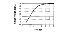
- FIG. 1 is a graph showing the results of calculating the average color rendering index Ra for various wavelengths and the number of lasers.
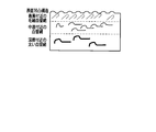
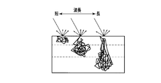
- FIG. 2A is a diagram schematically showing a cross-sectional structure of a biological mucous membrane.
- FIG. 2B is a diagram schematically illustrating the relationship between the wavelength length and the penetration depth.
- FIG. 3 is a diagram showing the wavelength dependence of the extinction coefficient of blood hemoglobin.
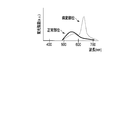
- FIG. 4A is a graph showing absorption intensity characteristics regarding the autofluorescent material.
- FIG. 4B is a graph showing fluorescence intensity characteristics.
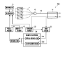
- FIG. 5 is a block diagram showing the configuration of the medical image forming apparatus according to the first embodiment of the present invention.
- FIG. 5 is a block diagram showing the configuration of the medical image forming apparatus according to the first embodiment of the present invention.
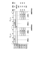
- FIG. 6 is a diagram illustrating an example of laser output conditions when all of the special light image 1, the special light image 2, the special light image 3, and the white light image are selected.
- FIG. 7 is a diagram illustrating an example of laser output conditions when special light images 1, 2, and 3 and a white light image are displayed simultaneously.
- FIG. 8 is a diagram illustrating an example of parallel display of four observation images.
- FIG. 9 is a diagram illustrating an example of laser output conditions when only the special light image 1 and the white light image are selected.
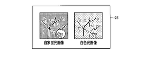
- FIG. 10 is a diagram illustrating an example of parallel display of two observation images.
- FIG. 11 is a block diagram showing a configuration of a medical image forming apparatus according to the second embodiment of the present invention.
- FIG. 12 is a diagram illustrating an example of laser output conditions when all of the special light image 1 and the white light image are selected in the second embodiment of the present invention.
- FIG. 13 is a diagram illustrating an example of parallel display of two observation images according to the second embodiment of the present invention.
- the applicant performed calculation of the average color rendering index Ra, which is one of the illuminator quality evaluation parameters defined in Japanese Industrial Standards (JIS), for various wavelengths and the number of lasers. As a result, as shown in FIG. 1, it has been found that by combining a plurality of laser beams having different wavelengths, a performance equivalent to or higher than the broad spectrum general illumination conventionally used can be obtained. It was. Specifically, if there are at least four lasers, the average color rendering index Ra is 80, and sufficient performance as an illumination light source can be obtained.
- JIS Japanese Industrial Standards
- the laser can output light with high light density and parallelism from a light emitting area smaller than a gas light source or LED. Therefore, a laser as a light source for white light observation that requires color rendering is introduced with high efficiency into a small-diameter light guide member such as a fiber in an observation apparatus that is expected to be observed in a closed space such as an endoscope apparatus. Easy to use (low power consumption, high brightness lighting). In addition, for special light observations that have been actively developed in the field of endoscopes in recent years, the narrow spectral characteristics of the laser also provide the advantage of easily acquiring the wavelength characteristics of specific substances at the target site. be able to. Special light observation includes, for example, observation of a blood vessel enhancement image, an oxygen saturation image, and an autofluorescence image. Hereinafter, each observation image will be described.
- wavelength light (B light) having a short wavelength penetrates only to the vicinity of the surface layer, and is absorbed and scattered in the vicinity thereof.
- the return light at this time is emitted from the surface of the living body.
- the wavelength light (G light) having a medium wavelength penetrates to a range deeper than the surface layer, and is absorbed and scattered in the vicinity thereof.
- the return light at this time is emitted from the surface of the living body. With this return light, it is possible to acquire information in a deeper part than light having a short wavelength.
- wavelength light (R light) having a long wavelength (on the order of 600 nm) penetrates to a deeper range and is absorbed and scattered in the vicinity thereof.
- the return light at this time is emitted from the surface of the living body. With this return light, it is possible to acquire information in a deeper part than light having a medium wavelength.
- FIG. 3 shows the wavelength dependence of the extinction coefficient of blood hemoglobin. As shown in FIG. 3, the absorption spectra are slightly different between oxygenated hemoglobin and reduced hemoglobin. When light of the first half wavelength of the 400nm range, which has a high hemoglobin extinction coefficient, is irradiated toward the living body, it is possible to obtain an image that emphasizes the blood vessels that are mainly present on the surface of the living body.
- Oxygen saturation image The oxygen saturation of hemoglobin is calculated by obtaining the amount of oxyhemoglobin relative to the amount of total hemoglobin.
- the wavelengths of 450 nm, 540 nm, and 805 nm are wavelengths with almost no difference in extinction coefficient between oxyhemoglobin and reduced hemoglobin.
- wavelengths of 430 nm, 560 nm, and 760 nm are wavelengths having a larger extinction coefficient of reduced hemoglobin
- wavelengths of 470 nm, 590 nm, and 840 nm are wavelengths having a greater extinction coefficient of oxyhemoglobin.
- the image information of each wavelength band thus obtained is assigned to, for example, each color of red, green, and blue.
- an observation image is an oxygen saturation image.
- the light penetration length is longer for longer wavelengths, so when using light with a wavelength in the 400 nm range, the oxygen saturation image for the surface blood vessels is used with light having a wavelength in the 500 nm range.
- FIG. 4A is a graph showing the absorption intensity characteristic regarding the autofluorescent substance
- FIG. 4B is a graph showing the fluorescence intensity characteristic.
- These graphs show absorption intensity characteristics and fluorescence intensity characteristics of Flavin Adenine Dinucleotide (FAD) and porphyrin, which are autofluorescent substances correlated with tumors.
- FAD Flavin Adenine Dinucleotide
- porphyrin generates fluorescence by light having a central wavelength of 400 nm
- FAD generates fluorescence by light having central wavelengths of 380 nm and 450 nm.
- An image obtained by imaging such fluorescence is an autofluorescence image.
- the fluorescence intensity of autofluorescence differs between the lesioned part and the normal part. That is, fluorescence having a peak near 550 nm is generated in the normal part, while fluorescence having two peaks of 560 nm and 630 nm is generated in the lesion site. It is known that porphyrin accumulates in lesions such as cancer. Therefore, the fluorescence at 630 nm for the lesion site shown in FIG. 4B is fluorescence derived from porphyrin.
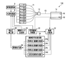
- FIG. 5 is a block diagram showing the configuration of the medical image forming apparatus according to the first embodiment of the present invention.
- the medical image forming apparatus 100 displays a special light image 1, a special light image 2, a special light image 3, and a white light image with high image accuracy.
- the special light image is an observation image obtained by irradiating with light of a specific wavelength, in which specific features of the observation target are emphasized.
- An example of the special light image 1 is an autofluorescence image.
- the special light image 2 of an example is a blood vessel emphasis image.
- the special light image 3 as an example is an oxygen saturation image.
- the white light image is a normal observation image obtained by irradiating with white light, in which specific features of the observation target are not emphasized. This white light image is used for screening or the like.
- the medical image forming apparatus 100 shown in FIG. 5 has laser light emitting elements (hereinafter simply referred to as lasers) 1 to 7 as illumination light sources.
- lasers are, for example, semiconductor lasers and have different emission wavelengths.
- laser 1 emits light with a wavelength of 400 nm
- laser 2 emits light with a wavelength of 450 nm
- laser 3 emits light with a wavelength of 420 nm
- laser 4 emits light with a wavelength of 540 nm.
- the laser 5 emits light of 640 nm
- the laser 6 emits light of 590 nm
- the laser 7 emits light of 560 nm.
- Lasers 1 to 7 are connected to the light source control unit 8.
- the light source control unit 8 is connected to the image selection unit 9 and the observation mode storage unit 10.
- the image selection unit 9 is an operation member such as a touch panel, for example, and accepts an operation for selecting the type of observation image by the user.
- the observation mode storage unit 10 stores laser output conditions (laser lighting start timing, lighting period, lighting cycle, etc.) for each observation mode suitable for the combination of observation images selected by the image selection unit 9.
- the light source control unit 8 acquires the laser output condition corresponding to the observation mode from the observation mode storage unit 10 and forms the observation image selected by the image selection unit 9 in accordance with the acquired laser output condition. Control lighting. Details will be described later.
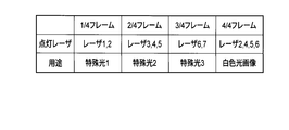
- Examples of laser output conditions when all of special light image 1 (autofluorescence image), special light image 2 (blood vessel enhancement image), special light image 3 (oxygen saturation image), and white light image are selected.
- This laser output condition is a laser output condition for an observation mode in which four selected observation images are displayed simultaneously.
- the image display cycle is 1 frame
- 1/4 frame is a period for forming the special light image 1
- the lasers 1 and 2 are turned on during this period.
- the 2/4 frame is a period for forming the special light image 2
- the lasers 3, 4, and 5 are turned on during this period.
- the 3/4 frame is a period for forming the special light image 3, and the lasers 6 and 7 are turned on during this period.
- the 4/4 frame is a period for forming a white light image, and the lasers 2, 4, 5, and 6 are turned on during this period.
- the laser used for forming the special light image is also used for forming the white light image. For this reason, the number of lasers may be seven.
- the lasers 1 to 7 are connected to the combiner 12 via the optical fiber 11.
- the combiner 12 combines a plurality of laser beams guided by the optical fiber 11.
- the combiner 12 is connected to a light distribution conversion member 16 provided at the distal end of the scope insertion portion 14 via an optical fiber 13.
- the light distribution conversion member 16 adjusts the light distribution of the mixed light guided by the optical fiber 13 to a state suitable for imaging (for example, an optimal light distribution spread angle) and emits the light toward an observation target (not shown).
- the light distribution conversion member 16 is, for example, a lens, a surface diffusing member having a light diffusing function on the surface, an internal diffusing member containing a minute member having a different refractive index or reflectance, or a combination thereof.
- a composite optical member is desirable.
- the imaging unit 18 includes, for example, R (red), G (green), and B (blue) imaging elements (for example, CCD imaging elements) that are regularly arranged on the same plane.
- the R image sensor is an image sensor having a sensitivity peak in the R wavelength band (near 600 nm).
- the G image sensor is an image sensor having a sensitivity peak in the G wavelength band (near 540 nm).
- the B image sensor is an image sensor having a peak of sensitivity in the B wavelength band (around 480 nm).
- Each of these imaging elements generates light-specific image signals by photoelectrically converting light in the corresponding wavelength band.
- the illumination imaging synchronization unit 20 is connected to the imaging unit 18.
- the illumination imaging synchronization unit 20 is also connected to the light source control unit 8 and the image distribution unit 22.
- the illumination imaging synchronization unit 20 synchronizes illumination by the lasers 1 to 7, imaging by the imaging unit 18, and image distribution by the image distribution unit 22, so that the light source control unit 8, the imaging unit 18, and the image distribution unit 22 are synchronized. And a sync signal is output.
- the imaging unit 18 is connected to the image distribution unit 22.
- the image distribution unit 22 includes a plurality of image forming units provided in the image signal processing circuit 24, that is, a special light 1 image forming unit 24a, a special light 2 image forming unit 24b, a special light 3 image forming unit 24c, and white light. It is connected to each of the image forming units 24d.
- the image distribution unit 22 transmits the image signal received from the imaging unit 18 to the corresponding image forming unit in response to the input of the synchronization signal from the illumination imaging synchronization unit 20.
- the special light 1 image forming unit 24a forms a special light image 1 (autofluorescence image) from the received image signal.
- the special light 2 image forming unit 24b forms the special light image 2 (blood vessel emphasized image) from the received image signal.
- the special light 3 image forming unit 24c forms a special light image 3 (oxygen saturation image) from the received image signal.
- the white light image forming unit 24d forms a white light image from the received image signal.
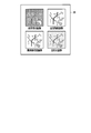
- the image display unit 26 receives the observation image formed by the image forming unit of the image signal processing circuit 24 and displays it in a state that is easy for the user or the like to understand. For example, the image display unit 26 divides one screen into four and displays each observation image in parallel.
- the brightness correction unit 28 receives the observation image from the image display unit 26 and determines the brightness of the observation image displayed on the image display unit 26. Then, when the brightness of the observation image displayed on the image display unit 26 is not appropriate, a correction signal is output to the light source control unit 8 so that the brightness of the observation image becomes appropriate.
- an observation image is selected by an operation of the image selection unit 9 by the user.
- the light source control unit 8 acquires a laser output condition corresponding to the observation mode suitable for the selected observation image from the observation mode storage unit 10.
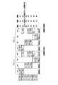
- FIG. 7 shows an example of laser output conditions when the special light images 1, 2, and 3 and the white light image are displayed simultaneously.
- the laser 1 is used only for forming the special light image 1 (autofluorescence image). Therefore, the lighting start timing of the laser 1 is the start timing of 1/4 frame, which is the formation period of the special light image 1.
- the lighting period of the laser 1 is a quarter of one frame. Further, the lighting cycle is a period of one frame.
- the laser 2 is used for forming the special light image 1 and the white light image. Therefore, the lighting start timing of the laser 2 is the start timing of 1/4 frame, which is the formation period of the special light image 1, and the start timing of 4/4 frame, which is the formation period of the white light image.
- the 4/4 frame and the 1/4 frame are continuous. Therefore, the actual lighting start timing of the laser 2 is the start timing of the 1/4 frame and the start timing of the 4/4 frame only for the first frame, and the start timing of the 4/4 frame in the previous frame after the second frame It is.
- the lighting period of the laser 2 is a quarter period of one frame only for the first quarter frame, and is a half period of one frame thereafter. Further, the lighting cycle of the laser 2 is a period of 3/4 of one frame only during the period from the first frame 1/4 to the frame 4/4, and thereafter is a period of one frame.
- the laser 3 is used only for forming the special light image 2 (blood vessel enhanced image). Therefore, the lighting start timing of the laser 3 is a start timing of 2/4 frame, which is the formation period of the special light image 2.
- the lighting period of the laser 3 is a quarter period of one frame. Further, the lighting cycle is a period of one frame.
- the laser 4 is used to form the special light image 2 and the white light image.
- the lighting start timing of the laser 4 is the start timing of the 2/4 frame that is the formation period of the special light image 2 and the start timing of the 4/4 frame that is the formation period of the white light image.
- the lighting period of the laser 4 is a quarter of one frame.
- the lighting cycle is a period of 1/2 frame.
- the laser 5 is used to form the special light image 2 and the white light image. Therefore, the lighting start timing of the laser 5 is the start timing of 2/4 frame, which is the formation period of the special light image 2, and the start timing of 4/4 frame, which is the formation period of the white light image.
- the lighting period of the laser 5 is a quarter of one frame. Further, the lighting cycle is a period of 1/2 frame.
- the laser 6 is used for forming a special light image 3 (oxygen saturation image) and a white light image. Therefore, the lighting start timing of the laser 6 is the start timing of the 3/4 frame that is the formation period of the special light image 3 and the start timing of the 4/4 frame that is the formation period of the white light image. Since the 3/4 frame and the 4/4 frame are continuous, the actual lighting start timing of the laser 6 is the start timing of the 3/4 frame.
- the lighting period of the laser 6 is a half period of one frame. Further, the lighting cycle is a period of one frame.
- the laser 7 is used only for forming the special light image 3. Accordingly, the lighting start timing of the laser 7 is the start timing of the 3/4 frame that is the formation period of the special light image 3.
- the lighting period of the laser 7 is a quarter of one frame. Further, the lighting cycle is a period of one frame.
- the light source control unit 8 turns on the lasers 1 to 7 in accordance with the output conditions as described above and the synchronization signal from the illumination imaging synchronization unit 20.
- the imaging unit 18 images the return light from the observation target of the laser light emitted from the lasers 1 to 7 in accordance with the synchronization signal from the illumination imaging synchronization unit 20, generates an image signal, and generates the generated image signal as an image distribution unit. 22 to send.
- the image distribution unit 22 identifies the type of observation image to be formed based on the synchronization signal from the illumination imaging synchronization unit 20, and the image signal received from the imaging unit 18 in accordance with the identification result is used as the special light 1 image formation unit 24a, the special light image formation unit 24a.
- the image is transmitted to a necessary image forming unit among the light 2 image forming unit 24b, the special light 3 image forming unit 24c, and the white light image forming unit 24d.
- the image forming unit forms a corresponding observation image from the received image signal, and transmits the formed observation image to the image display unit 26.
- the image display unit 26 displays the received observation image so that the user can easily see it. For example, as shown in FIG. 8, the image display unit 26 displays four observation images in parallel.
- the observation image formed by the image forming unit is input from the image display unit 26 to the brightness correction unit 28.
- the brightness correction unit 28 instructs the light source control unit 8 to correct the outputs of the lasers 1 to 7 so that the brightness of the observation image displayed on the image display unit 26 is appropriate.
- FIG. 9 shows an example of laser output conditions when only the special light image 1 and the white light image are selected.
- the two observation images are displayed in parallel as shown in FIG. In such an observation mode, it is only necessary to form two observation images in one frame. Therefore, as shown in FIG. 9, the lighting periods of the lasers 1, 4, 5, and 6 may be 1 ⁇ 2 period of one frame. Further, the laser 2 may be kept on.
- the observation image formation period can be lengthened. Therefore, if the period of one frame is the same as that of the example of FIG. Can be long. Therefore, in the example of FIG. 9, it is possible to display a brighter observation image than in the example of FIG.
- white light or special light is formed using a laser.
- the laser can be easily introduced into a thin light guide member such as a fiber with high efficiency, and can realize illumination light with considerably higher brightness than an LED light source or a gas light source.
- special light it is possible to acquire image information unique to only that wavelength compared to a light source having a broad spectrum such as an LED light source. Therefore, the image accuracy is high.
- a white light image is constructed by utilizing a part of the special light laser, the number of lasers can be reduced and the cost and volume can be reduced. Further, since four white light image lasers are prepared, the color rendering property of the white light image is ensured. Furthermore, since the other laser is not turned on when acquiring the white light image, a white light image with high image accuracy can be formed. In addition, since a plurality of types of special light image lasers are also made common, the number of lasers can be reduced to reduce cost and volume.
- the laser lighting start timing, the laser lighting period, and the laser lighting cycle corresponding to the observation mode in the observation mode storage unit 10 there is no useless driving of the laser. This can also reduce power consumption.
- individually changing the lighting cycle of different lasers it is possible to keep the lasers lit across frames in which different image types are captured. This makes it possible to illuminate the shared laser without a load in terms of circuitry. This also makes it possible to reduce power consumption.
- the illumination imaging synchronization unit 20 transfers an image signal to the image forming unit at an appropriate timing. This also makes it possible to reduce power consumption.
- the medical image forming apparatus 100 of the present embodiment has a configuration in which a white light image is generated only by a laser prepared for a special light image, but this is not a limitation. In the case of a configuration in which a high-quality white light image cannot be created with only a laser prepared for a special light image, a white light image laser may be separately prepared.
- the medical image forming apparatus 100 according to the present embodiment prepares different lasers for laser beams used for a plurality of types of special light. Also good. For example, the excitation center wavelength of porphyrin and the wavelength at which the oxide and hemoglobin-related spectra for hemoglobin match at 450 nm match. Therefore, the laser for forming the autofluorescence image and the laser for forming the oxygen saturation image may be only one 450 nm laser.
- FIG. 11 is a block diagram showing a configuration of a medical image forming apparatus according to the second embodiment of the present invention.
- the medical image forming apparatus 100 of this embodiment has a simpler configuration than that of the first embodiment. In the following, description of the configuration common to the first embodiment is omitted.
- the medical image forming apparatus 100 of the second embodiment includes lasers 1 to 4 as illumination light sources.
- laser 1 emits light with a wavelength of 400 nm
- laser 2 emits light with a wavelength of 450 nm
- laser 3 emits light with a wavelength of 540 nm
- laser 4 emits light with a wavelength of 640 nm.
- only two observation images of the special light image 1 (blood vessel emphasized image) and the white light image are formed at most. Therefore, there are only two image forming units.
- FIG. 12 shows an example of laser output conditions when only the special light image 1 and the white light image are selected in the second embodiment.
- the laser 1 and the laser 3 are turned on.
- the laser 2, the laser 3, and the laser 4 are turned on during the white light image formation period.
- the lighting cycle and the lighting period may be the same as those in FIG. In such a second embodiment, two observation images as shown in FIG. 13 are displayed in parallel.
- the number of lasers and the number of other members can be further reduced as compared with the first embodiment.
- individual functions can be simplified as compared with the first embodiment, it is possible to achieve cost reduction, volume reduction, and power consumption reduction as compared with the first embodiment.
- the laser lighting period and the imaging period for one observation image are maximized within one frame. As a result, an image with high image accuracy can be acquired.
Landscapes
- Health & Medical Sciences (AREA)
- Life Sciences & Earth Sciences (AREA)
- Surgery (AREA)
- Physics & Mathematics (AREA)
- Engineering & Computer Science (AREA)
- Optics & Photonics (AREA)
- Veterinary Medicine (AREA)
- Pathology (AREA)
- Public Health (AREA)
- Biophysics (AREA)
- Biomedical Technology (AREA)
- Heart & Thoracic Surgery (AREA)
- Medical Informatics (AREA)
- Molecular Biology (AREA)
- Animal Behavior & Ethology (AREA)
- General Health & Medical Sciences (AREA)
- Radiology & Medical Imaging (AREA)
- Nuclear Medicine, Radiotherapy & Molecular Imaging (AREA)
- General Physics & Mathematics (AREA)
- Astronomy & Astrophysics (AREA)
- Signal Processing (AREA)
- Multimedia (AREA)
- Spectroscopy & Molecular Physics (AREA)
- Theoretical Computer Science (AREA)
- Endoscopes (AREA)
- Exposure Control For Cameras (AREA)
- Stroboscope Apparatuses (AREA)
- Closed-Circuit Television Systems (AREA)
Abstract
医療用画像形成装置(100)は、異なる波長のレーザ光を発するレーザ発光素子(1)~(7)と、観察画像の種類を選択するための画像選択部(9)と、選択された観察画像の組み合わせに応じた観察モードに従ってレーザ発光素子(1)~(7)の点灯制御を行う光源制御部(8)と、観察対象からのレーザ光の戻り光を撮像する撮像部(18)と、撮像部(18)からの画像信号から観察画像を形成する画像信号処理回路(24)とを有している。光源制御部(8)は、第1の観察画像が選択された場合にレーザ発光素子(1)~(7)の少なくとも1つを点灯させ、第2の観察画像が選択された場合に第1の観察画像の場合に点灯させるレーザ発光素子の少なくとも1つを点灯させる。
Description
本発明は、医療用画像形成装置に関する。
従来から用いられている気体光源等に対し、固体光源は、低消費電力、高接続効率、小型、高速切替可能等の長所を有する。このような固体光源に対する技術革新は目覚しい。このような固体光源のうち、特に、固体レーザは出射面積内の光密度が極めて高いという特性を有している。この特性により、固体レーザを例えば光ファイバと組み合わせることによって構成された、いわゆるファイバ光源が活発に開発されている。ファイバ光源は、細い構造物内を照明するのに好適であり、内視鏡等への応用が進められている。
ファイバ光源を用いた医療用画像形成装置の例として、例えば、日本国特開2011-200572号公報は、白色光画像に加え、微細血管画像、酸素飽和度画像、血管深さ画像の中から、使用者等によって選ばれた1種又は2種の画像を同時に取得して同時に表示することができる電子内視鏡システムを提供している。日本国特開2011-200572号公報においては、広帯域光用の複数の固体光源、微細血管画像用の複数のレーザ、酸素飽和度画像用の複数のレーザ、及び血管深さ画像用の複数のレーザが光源として設けられている。そして、日本国特開2011-200572号公報は、選択された画像に応じた複数の光源を同時に又は順次に対象物に照射させることにより、複数の画像を取得している。
日本国特開2011-200572号公報では、選択できる画像毎に専用のレーザが設けられている。このため、選択できる画像の数が多くなると、レーザの数が多くなって製造コストが高くなり、かつ、容積も大きくなってしまう。また、画像向けの複数のレーザの波長が近接していたとしてもそれらの複数のレーザを順次照射しなければならないため、回路に対する負荷が大きく、高消費電力に繋がり易い。さらに、日本国特開2011-200572号公報では、波長的に近接しているレーザを同時に照射して、別々の特殊光画像を構築している。このとき、各波長の受光強度に対する推定を行っており、画像再現正確度が低くなり易い。
本発明は、前記の事情に鑑みてなされたものであり、低コスト化、低容積化、低消費電力化を実現しつつ、画像再現正確度の高い医療用画像形成装置を提供することを目的とする。
前記の目的を達成するために、本発明の一態様の医療用画像形成装置は、異なる波長のレーザ光を発する複数のレーザ発光素子と、観察画像の種類を選択するための画像選択部と、前記選択された観察画像の組み合わせに応じた観察モードに従って前記複数のレーザ発光素子の点灯制御を行う光源制御部と、観察対象からの前記レーザ光の戻り光を撮像して画像信号として出力する撮像部と、前記撮像部からの画像信号から前記観察画像を形成する画像信号処理回路とを具備し、前記選択された観察画像の種類が第1の観察画像である場合に前記光源制御部によって点灯制御されるレーザ発光素子と前記選択された観察画像の種類が第2の観察画像である場合に前記光源制御部によって点灯制御されるレーザ発光素子との間には共通の波長のレーザ光を発するレーザ発光素子が含まれている。
以下、図面を参照して本発明の実施形態を説明する。まず、本実施形態の前提となる技術について説明する。従来、高品質で、かつ、画像再現正確度の高い白色照明装置には、可視光全体に渡り波長欠落のない光が出射されることが不可欠と考えられてきた。しかしながら、近年、レーザ光のような単波長光を複数組み合わせた照明光でも、十分に照明光としての性能(演色性)が高いことが明らかとなってきている(例えば、A. Neumann et al., Opt. Exp., 19, S4, A982(July 4, 2011)参照)。
出願人は、日本工業規格(JIS)等で定められている照明器品質評価パラメータの一つである平均演色指数Raの計算を、様々な波長やレーザ本数に対して行った。この結果、図1のように、複数本の波長の異なるレーザ光をうまく組み合わせることで、従来から用いられてきたブロードなスペクトルの一般照明と同等か、それ以上の性能が得られることがわかってきた。具体的には、レーザが少なくとも4本あれば、平均演色指数Raが80となり、照明光源として十分な性能を得ることができる。
レーザは、気体光源やLEDよりも小さな発光領域から光密度と平行度の高い光を出力させることができる。したがって、演色性が必要な白色光観察用光源としてのレーザは、内視鏡装置のような閉空間内の観察が想定される観察装置におけるファイバ等の細径導光部材に高効率に導入しやすいという利点がある(低消費電力、高輝度照明)。また、近年内視鏡分野で開発が盛んに行われている特殊光観察に対しても、レーザの狭スペクトル性により、対象部位の特定物質に対する波長的特徴を正確に取得しやすい利点をも得ることができる。特殊光観察とは、例えば血管強調画像、酸素飽和度画像、自家蛍光画像の観察が挙げられる。以下、それぞれの観察画像について説明する。
1、血管強調画像
生体内に紫外光から近赤外光の領域内の光を照射した場合、生体の持つ散乱特性や吸収特性により、長波長光を照射するほど光の侵達長が長くなることが知られている。例えば生体粘膜の断面構造が模式的に図2Aのようになっているとすると、生体に入射した光は、生体内におけるおおよそ侵達長の深さまで侵達し、その深さの範囲において吸収や散乱等を受けて戻ってくる。この戻り光を観察することにより、侵達長の深度周辺の情報を観察することができる。図2Bに示すように、短波長(400nm台)の波長光(B光)は、表層付近までしか侵達せず、その付近で吸収、散乱を受ける。このときの戻り光が生体表面から射出される。また、図2Bに示すように、中波長(500nm台)の波長光(G光)は、表層よりも深い範囲まで侵達し、その付近で吸収、散乱を受ける。このときの戻り光が生体表面から射出される。この戻り光により、短波長の波長光よりも深部の情報を取得することができる。さらにまた、図2Bに示すように、長波長(600nm台)の波長光(R光)は、さらに深い範囲まで侵達し、その付近で吸収、散乱を受ける。このときの戻り光が生体表面から射出される。この戻り光により、中波長の波長光よりも深部の情報を取得することができる。
生体内に紫外光から近赤外光の領域内の光を照射した場合、生体の持つ散乱特性や吸収特性により、長波長光を照射するほど光の侵達長が長くなることが知られている。例えば生体粘膜の断面構造が模式的に図2Aのようになっているとすると、生体に入射した光は、生体内におけるおおよそ侵達長の深さまで侵達し、その深さの範囲において吸収や散乱等を受けて戻ってくる。この戻り光を観察することにより、侵達長の深度周辺の情報を観察することができる。図2Bに示すように、短波長(400nm台)の波長光(B光)は、表層付近までしか侵達せず、その付近で吸収、散乱を受ける。このときの戻り光が生体表面から射出される。また、図2Bに示すように、中波長(500nm台)の波長光(G光)は、表層よりも深い範囲まで侵達し、その付近で吸収、散乱を受ける。このときの戻り光が生体表面から射出される。この戻り光により、短波長の波長光よりも深部の情報を取得することができる。さらにまた、図2Bに示すように、長波長(600nm台)の波長光(R光)は、さらに深い範囲まで侵達し、その付近で吸収、散乱を受ける。このときの戻り光が生体表面から射出される。この戻り光により、中波長の波長光よりも深部の情報を取得することができる。
図3は、血中ヘモグロビンの吸光係数の波長依存性を示している。図3に示すように、酸化ヘモグロビンと還元ヘモグロビンとで、若干吸収スペクトルが異なっている。ヘモグロビンの吸光係数の高い400nm台の前半の波長の光が生体に向けて照射された場合、主に生体表層に存在する血管が強調された画像が取得でき、同じく、ヘモグロビンの吸光係数の高い500nm台の波長の光が生体に向けて照射された場合、主に生体中層に存在する血管が強調された画像が取得でき、600nm以上の波長の光が生体に向けて照射された場合、主に深層に存在する血管が強調された画像が取得できる。これらの観察画像が血管強調画像である。
2、酸素飽和度画像
ヘモグロビンの酸素飽和度は、全ヘモグロビンの量に対する酸化ヘモグロビンの量を得ることにより算出される。図3から分かるように、450nm、540nm、805nmの波長は、酸化ヘモグロビンと還元ヘモグロビンとの吸光係数の差がほとんどない波長である。一方430nm、560nm、760nmの波長は還元ヘモグロビンの方の吸光係数が大きい波長であり、470nm、590nm、840nmの波長は酸化ヘモグロビンの方の吸光係数が大きい波長である。このように、酸化ヘモグロビンと還元ヘモグロビンとで吸光係数が逆転する波長の光を選んで生体に照射し、これにより得られた各波長帯域の画像情報を例えば赤、緑、青の各色に割り当てて観察することにより、酸素飽和度の変化を画像の色の変化として捉えやすくなる。このような観察画像が酸素飽和度画像である。ここで、上述のように光の侵達長は長波長ほど長いので、400nm台の波長の光を用いた場合には表層血管に関する酸素飽和度画像を、500nm台の波長の光を用いた場合には中層血管に関する酸素飽和度画像を、600nm以上の波長の光を用いた場合には深層血管に関する酸素飽和度画像をそれぞれ表示させることができる。
ヘモグロビンの酸素飽和度は、全ヘモグロビンの量に対する酸化ヘモグロビンの量を得ることにより算出される。図3から分かるように、450nm、540nm、805nmの波長は、酸化ヘモグロビンと還元ヘモグロビンとの吸光係数の差がほとんどない波長である。一方430nm、560nm、760nmの波長は還元ヘモグロビンの方の吸光係数が大きい波長であり、470nm、590nm、840nmの波長は酸化ヘモグロビンの方の吸光係数が大きい波長である。このように、酸化ヘモグロビンと還元ヘモグロビンとで吸光係数が逆転する波長の光を選んで生体に照射し、これにより得られた各波長帯域の画像情報を例えば赤、緑、青の各色に割り当てて観察することにより、酸素飽和度の変化を画像の色の変化として捉えやすくなる。このような観察画像が酸素飽和度画像である。ここで、上述のように光の侵達長は長波長ほど長いので、400nm台の波長の光を用いた場合には表層血管に関する酸素飽和度画像を、500nm台の波長の光を用いた場合には中層血管に関する酸素飽和度画像を、600nm以上の波長の光を用いた場合には深層血管に関する酸素飽和度画像をそれぞれ表示させることができる。
3、自家蛍光画像
図4Aは自家蛍光物質に関する吸収強度特性を表すグラフであり、図4Bは蛍光強度特性を表すグラフである。これらのグラフには、腫瘍と相関のある自家蛍光物質であるFlavin Adenine Dinucleotide(FAD)及びポルフィリンの吸収強度特性及び蛍光強度特性が示されている。図4Aのグラフから分かるように、ポルフィリンは中心波長400nmの光によって蛍光を発生し、FADは中心波長380nm及び450nmの光によって蛍光を発生する。このような蛍光を撮像して画像としたものが自家蛍光画像である。ここで、自家蛍光の蛍光強度は、病変部と正常部で異なる。すなわち、正常部では550nm付近にピークを有する蛍光が発生する一方、病変部位では、560nmと630nmの2つのピークを有する蛍光が発生する。癌等の病変部においては、ポルフィリンが蓄積されることが知られている。したがって、図4Bに示す病変部位に関する630nmの蛍光はポルフィリンに由来する蛍光である。このように、ポルフィリンの蛍光強度の違いを捉えることにより、正常部と病変部とを区別することが可能である(参考文献:田村守、「シリーズ/光が拓く生命科学 第6巻 光による医学診断」、日本光生物学協会編、共立出版、2001年3月18日)。
図4Aは自家蛍光物質に関する吸収強度特性を表すグラフであり、図4Bは蛍光強度特性を表すグラフである。これらのグラフには、腫瘍と相関のある自家蛍光物質であるFlavin Adenine Dinucleotide(FAD)及びポルフィリンの吸収強度特性及び蛍光強度特性が示されている。図4Aのグラフから分かるように、ポルフィリンは中心波長400nmの光によって蛍光を発生し、FADは中心波長380nm及び450nmの光によって蛍光を発生する。このような蛍光を撮像して画像としたものが自家蛍光画像である。ここで、自家蛍光の蛍光強度は、病変部と正常部で異なる。すなわち、正常部では550nm付近にピークを有する蛍光が発生する一方、病変部位では、560nmと630nmの2つのピークを有する蛍光が発生する。癌等の病変部においては、ポルフィリンが蓄積されることが知られている。したがって、図4Bに示す病変部位に関する630nmの蛍光はポルフィリンに由来する蛍光である。このように、ポルフィリンの蛍光強度の違いを捉えることにより、正常部と病変部とを区別することが可能である(参考文献:田村守、「シリーズ/光が拓く生命科学 第6巻 光による医学診断」、日本光生物学協会編、共立出版、2001年3月18日)。
[第1の実施形態]
図5は、本発明の第1の実施形態に係る医療用画像形成装置の構成を示すブロック図である。この医療用画像形成装置100は、特殊光画像1、特殊光画像2、特殊光画像3、白色光画像を画像正確性高く表示させるものである。特殊光画像は、特定の波長の光の照射により得られる、観察対象の特定の特徴が強調された観察画像である。一例の特殊光画像1は、自家蛍光画像である。また、一例の特殊光画像2は、血管強調画像である。さらに、一例の特殊光画像3は、酸素飽和度画像である。また、白色光画像は、白色光が照射されることにより得られる、観察対象の特定の特徴が強調されていない通常の観察画像である。この白色光画像は、スクリーニング等に用いられる。
図5は、本発明の第1の実施形態に係る医療用画像形成装置の構成を示すブロック図である。この医療用画像形成装置100は、特殊光画像1、特殊光画像2、特殊光画像3、白色光画像を画像正確性高く表示させるものである。特殊光画像は、特定の波長の光の照射により得られる、観察対象の特定の特徴が強調された観察画像である。一例の特殊光画像1は、自家蛍光画像である。また、一例の特殊光画像2は、血管強調画像である。さらに、一例の特殊光画像3は、酸素飽和度画像である。また、白色光画像は、白色光が照射されることにより得られる、観察対象の特定の特徴が強調されていない通常の観察画像である。この白色光画像は、スクリーニング等に用いられる。
図5に示す医療用画像形成装置100は、照明用光源として、レーザ発光素子(以下、単にレーザと言う)1~7を有する。これらのレーザは、例えば半導体レーザであって発光波長が異なっている。一例においては、レーザ1は400nmの波長の光を照射し、レーザ2は450nmの波長の光を照射し、レーザ3は420nmの波長の光を照射し、レーザ4は540nmの波長の光を照射し、レーザ5は640nmの光を照射し、レーザ6は590nmの光を照射し、レーザ7は560nmの光を照射する。
レーザ1~7は、光源制御部8に接続されている。また、光源制御部8は、画像選択部9及び観察モード記憶部10に接続されている。画像選択部9は、例えばタッチパネルのような操作部材であって、使用者による観察画像の種類の選択操作を受け付ける。観察モード記憶部10は、画像選択部9によって選択された観察画像の組み合わせに適した観察モード毎のレーザ出力条件(レーザの点灯開始タイミング、点灯期間、点灯周期等)を記憶している。光源制御部8は、観察モード記憶部10から観察モードに応じたレーザ出力条件を取得し、取得したレーザ出力条件に従って画像選択部9で選択された観察画像が形成できるようにレーザ1~7の点灯制御をする。詳細については後で説明する。
例えば、特殊光画像1(自家蛍光画像)、特殊光画像2(血管強調画像)、特殊光画像3(酸素飽和度画像)、白色光画像の全てが選択された場合のレーザ出力条件の例を図6に示す。このレーザ出力条件は、選択された4つの観察画像を同時表示する観察モードについてのレーザ出力条件である。画像が表示される周期を1フレームとしたとき、図6の例では、1/4フレームが特殊光画像1を形成するための期間であって、この期間中にはレーザ1、2が点灯される。また、2/4フレームが特殊光画像2を形成するための期間であって、この期間中にはレーザ3、4、5が点灯される。また、3/4フレームが特殊光画像3を形成するための期間であって、この期間中にはレーザ6、7が点灯される。また、4/4フレームが白色光画像を形成するための期間であって、この期間中にはレーザ2、4、5、6が点灯される。本実施形態では、特殊光画像の形成に使用されるレーザが白色光画像の形成にも使用される。このため、レーザの本数は7本でよい。
また、レーザ1~7は、光ファイバ11を介してコンバイナ12に接続されている。コンバイナ12は、光ファイバ11によって導波された複数のレーザ光を合波する。また、コンバイナ12は、光ファイバ13を介してスコープ挿入部14の先端に設けられた配光変換部材16に接続されている。配光変換部材16は、光ファイバ13によって導波された混合光の配光を撮像に適した状態(例えば最適な配光広がり角)に調整して、図示しない観察対象に向けて射出する。ここで、配光変換部材16は、例えば、レンズ、表面において光拡散機能を有する表面拡散部材、内部に屈折率や反射率の異なる微小部材の何れかを含有した内部拡散部材又はそれらの組み合わせである複合光学部材であることが望ましい。
スコープ挿入部14の先端には、さらに、撮像部18が設けられている。撮像部18は、同一平面上に規則的に複数個ずつ配置された、例えばR(赤色)、G(緑色)、B(青色)の撮像素子(例えばCCD撮像素子)を有している。Rの撮像素子は、Rの波長帯域(600nm付近)に感度のピークを有する撮像素子である。同様に、Gの撮像素子は、Gの波長帯域(540nm付近)に感度のピークを有する撮像素子である。Bの撮像素子は、Bの波長帯域(480nm付近)に感度のピークを有する撮像素子である。これらの撮像素子は、それぞれ、対応する波長帯域の光を光電変換して色別の画像信号を生成する。
撮像部18には、照明撮像同期部20が接続されている。また、照明撮像同期部20は、光源制御部8及び画像分配部22にも接続されている。照明撮像同期部20は、レーザ1~7による照明と、撮像部18による撮像と、画像分配部22による画像分配とを同期させるため、光源制御部8と、撮像部18と、画像分配部22とに同期信号を出力する。
撮像部18は、画像分配部22に接続されている。また、画像分配部22は、画像信号処理回路24に設けられた複数の画像形成部、すなわち特殊光1画像形成部24a、特殊光2画像形成部24b、特殊光3画像形成部24c、白色光画像形成部24dのそれぞれに接続されている。画像分配部22は、照明撮像同期部20からの同期信号の入力に応じて撮像部18から受信した画像信号を対応する画像形成部に送信する。特殊光1画像形成部24aは、受信した画像信号から特殊光画像1(自家蛍光画像)を形成する。特殊光2画像形成部24bは、受信した画像信号から特殊光画像2(血管強調画像)を形成する。特殊光3画像形成部24cは、受信した画像信号から特殊光画像3(酸素飽和度画像)を形成する。白色光画像形成部24dは、受信した画像信号から白色光画像を形成する。
画像表示部26は、画像信号処理回路24の画像形成部で形成された観察画像を受信し、使用者等にとってわかりやすい状態で表示する。例えば、画像表示部26は、1画面を4分割してそれぞれの観察画像を並列表示する。
明るさ補正部28は、画像表示部26から観察画像を受信して、画像表示部26に表示されている観察画像の明るさを判別する。そして、画像表示部26に表示されている観察画像の明るさが適切な明るさでない場合に、観察画像の明るさが適切な明るさとなるように、光源制御部8に補正信号を出力する。
次に本実施形態に係る医療用画像形成装置100の動作を説明する。まず、使用者による画像選択部9の操作によって観察画像の選択が行われる。一例においては、特殊光画像1、2、3と白色光画像との全てが選択されたとする。観察画像の選択が行われると、光源制御部8は、選択された観察画像に適した観察モードに応じたレーザ出力条件を観察モード記憶部10から取得する。図7は、特殊光画像1、2、3と白色光画像とを同時表示させる場合のレーザ出力条件の例を示している。図7に示すように、レーザ1は、特殊光画像1(自家蛍光画像)の形成にのみ用いられる。したがって、レーザ1の点灯開始タイミングは、特殊光画像1の形成期間である1/4フレームの開始タイミングである。また、レーザ1の点灯期間は、1フレームの1/4の期間である。さらに、点灯周期は、1フレームの期間である。これに対し、レーザ2は、特殊光画像1の形成と白色光画像の形成とに用いられる。したがって、レーザ2の点灯開始タイミングは、特殊光画像1の形成期間である1/4フレームの開始タイミングと白色光画像の形成期間である4/4フレームの開始タイミングである。ただし、繰り返し表示が行われる場合、図7に示すように、4/4フレームと1/4フレームとが連続することになる。したがって、実際のレーザ2の点灯開始タイミングは、最初のフレームのみ1/4フレームの開始タイミングと4/4フレームの開始タイミングであり、2フレーム目以降は前のフレームにおける4/4フレームの開始タイミングである。また、レーザ2の点灯期間は、最初の1/4フレームのみ1フレームの1/4の期間であり、それ以後は1フレームの1/2の期間である。さらに、レーザ2の点灯周期は、最初のフレーム1/4からフレーム4/4の期間のみ1フレームの3/4の期間であり、それ以後は1フレームの期間である。また、レーザ3は、特殊光画像2(血管強調画像)の形成にのみ用いられる。したがって、レーザ3の点灯開始タイミングは、特殊光画像2の形成期間である2/4フレームの開始タイミングである。また、レーザ3の点灯期間は、1フレームの1/4の期間である。さらに、点灯周期は、1フレームの期間である。また、レーザ4は、特殊光画像2の形成と白色光画像の形成とに用いられる。したがって、レーザ4の点灯開始タイミングは、特殊光画像2の形成期間である2/4フレームの開始タイミングと白色光画像の形成期間である4/4フレームの開始タイミングである。また、レーザ4の点灯期間は、1フレームの1/4の期間である。さらに、点灯周期は、1/2フレームの期間である。また、レーザ5は、特殊光画像2の形成と白色光画像の形成とに用いられる。したがって、レーザ5の点灯開始タイミングは、特殊光画像2の形成期間である2/4フレームの開始タイミングと白色光画像の形成期間である4/4フレームの開始タイミングである。また、レーザ5の点灯期間は、1フレームの1/4の期間である。さらに、点灯周期は、1/2フレームの期間である。また、レーザ6は、特殊光画像3(酸素飽和度画像)の形成と白色光画像の形成とに用いられる。したがって、レーザ6の点灯開始タイミングは、特殊光画像3の形成期間である3/4フレームの開始タイミングと白色光画像の形成期間である4/4フレームの開始タイミングである。なお、3/4フレームと4/4フレームとは連続しているので、実際のレーザ6の点灯開始タイミングは、3/4フレームの開始タイミングである。また、レーザ6の点灯期間は、1フレームの1/2の期間である。さらに、点灯周期は、1フレームの期間である。また、レーザ7は、特殊光画像3の形成にのみ用いられる。したがって、レーザ7の点灯開始タイミングは、特殊光画像3の形成期間である3/4フレームの開始タイミングである。また、レーザ7の点灯期間は、1フレームの1/4の期間である。さらに、点灯周期は、1フレームの期間である。
以上のような出力条件と照明撮像同期部20からの同期信号とに従って光源制御部8は、レーザ1~7を点灯させる。撮像部18は、照明撮像同期部20からの同期信号に従ってレーザ1~7から照射されたレーザ光の観察対象からの戻り光を撮像して画像信号を生成し、生成した画像信号を画像分配部22に送信する。
画像分配部22は、照明撮像同期部20からの同期信号によって形成すべき観察画像の種類を識別し、この識別結果に従って撮像部18から受信した画像信号を、特殊光1画像形成部24a、特殊光2画像形成部24b、特殊光3画像形成部24c、及び白色光画像形成部24dのうちの必要な画像形成部に送信する。画像形成部は、受信した画像信号から対応する観察画像を形成し、形成した観察画像を画像表示部26に送信する。画像表示部26は、受信した観察画像を使用者が見やすいように表示する。画像表示部26は、例えば図8に示すように4つの観察画像を並列表示する。
また、画像形成部で形成された観察画像は、画像表示部26から明るさ補正部28に入力される。明るさ補正部28は、画像表示部26に表示される観察画像の明るさが適正になるように光源制御部8に対してレーザ1~7の出力の補正指示をする。
図9は、特殊光画像1と白色光画像のみが選択されたときのレーザ出力条件の例を示している。2つの観察画像のみが選択された場合、図10に示すような2つの観察画像の並列表示が行われる。このような観察モードでは、1フレームで2つの観察画像を形成できればよい。したがって、図9に示すように、レーザ1、4、5、6の点灯期間は、1フレームの1/2の期間でよい。また、レーザ2は、点灯させ続けてよい。図9の例では、観察画像の形成期間を長くできるので、1フレームの期間が図7の例と同じであれば、観察対象へのレーザ光の照射期間と撮像期間を図7の例よりも長くすることができる。したがって、図9の例では、図7の例よりも明るい観察画像を表示させることが可能である。
以上説明したように本実施形態においてはレーザを用いて白色光や特殊光を形成している。レーザはファイバ等の細径導光部材に高効率に導入しやすく、かつ、LED光源や気体光源と比べてかなりの明るさの照明光を実現することができる。また、レーザを用いて特殊光を形成することにより、LED光源等のブロードなスペクトルを有する光源と比較して、その波長だけに特有な像情報を取得することができる。したがって画像正確度が高い。
また、特殊光用レーザの一部を活用して白色光画像を構築しているので、レーザ本数を少なくして低コスト化及び低容積化を図ることができる。また、白色光画像用レーザは4灯用意されているので、白色光画像の演色性が確保される。さらに、白色光画像を取得する際に他のレーザが点灯されないので、画像正確性の高い白色光画像を形成することができる。また、複数種類の特殊光画像用レーザについても共通化させているため、よりレーザ数を少なくして低コスト化及び低容積化を図ることができる。
また、画像選択部9によって使用者の所望の画像のみが形成される。このため、不必要なレーザ点灯がなく、不必要な画像取得期間もない。したがって、1フレーム内で1つの観察画像に対するレーザの点灯期間及び撮像期間が最大化される。これにより、画像正確度の高い画像を取得することができる。
また、観察モード記憶部10に、観察モードに応じたレーザ点灯開始タイミング、レーザ点灯期間、レーザ点灯周期を記憶させておくことにより、無駄なレーザの駆動がない。これによっても低消費電力化を図ることができる。また、異なるレーザの点灯周期を個別に変化させることにより、画像種の異なる撮像を行っているフレームをまたいでレーザを点灯し続けさせることができる。これにより、共通化されたレーザを回路的に負荷無く照明させることができる。このことによっても低消費電力化を図ることができる。
照明撮像同期部20により、適切なタイミングで画像形成部に画像信号が転送される。
このことによっても低消費電力化を図ることができる。
このことによっても低消費電力化を図ることができる。
ここで、本実施形態の医療用画像形成装置100は特殊光画像用に用意したレーザのみで白色光画像を作り出すような構成を有しているが、その限りではない。特殊光画像用に用意したレーザのみでは、高品位な白色光画像が作り出せない構成の場合、白色光画像用レーザを別途用意しても良い。また、本実施形態の医療用画像形成装置100は複数種類の特殊光用に用いるレーザ光についてもそれぞれ別のレーザを用意したが、このことに関しても同一にすることができる技術があればしても良い。例えば、ポルフィリンの励起中心波長とヘモグロビンに関する酸化物と還元物スペクトルが一致する波長とは450nmで一致している。したがって自家蛍光画像の形成用のレーザと酸素飽和度画像の形成用のレーザは450nmのレーザ1本のみとしてもよい。
[第2の実施形態]
次に本発明の第2の実施形態について説明する。図11は、本発明の第2の実施形態に係る医療用画像形成装置の構成を示すブロック図である。本実施形態の医療用画像形成装置100は、第1の実施形態のものよりも単純な構成である。なお、以下においては第1の実施形態と共通の構成については説明を省略する。
次に本発明の第2の実施形態について説明する。図11は、本発明の第2の実施形態に係る医療用画像形成装置の構成を示すブロック図である。本実施形態の医療用画像形成装置100は、第1の実施形態のものよりも単純な構成である。なお、以下においては第1の実施形態と共通の構成については説明を省略する。
第2の実施形態の医療用画像形成装置100は、照明用光源として、レーザ1~4を有する。一例においては、レーザ1は400nmの波長の光を照射し、レーザ2は450nmの波長の光を照射し、レーザ3は540nmの波長の光を照射し、レーザ4は640nmの波長の光を照射する。また、第2の実施形態では最大でも特殊光画像1(血管強調画像)と白色光画像の2つの観察画像しか形成されない。したがって、画像形成部も2つのみである。
図12は、第2の実施形態において特殊光画像1と白色光画像のみが選択されたときのレーザ出力条件の例を示している。図12に示すように、特殊光画像1の形成期間では、レーザ1とレーザ3とが点灯される。また、白色光画像の形成期間では、レーザ2と、レーザ3と、レーザ4とが点灯される。点灯周期及び点灯期間は図9と同様でよい。このような第2の実施形態では、図13に示すような2つの観察画像の並列表示が行われる。
以上説明したように本実施形態によれば、レーザ本数やその他の部材数を第1の実施形態に比べてさら減らすことができる。また、第1の実施形態に比べて個々の機能を単純化することができるので、第1の実施形態に比べて低コスト化、低容積化、低消費電力化を図ることが可能となる。また、使用者にとって真に必要な観察モードだけが形成可能な構成となっているので、1フレーム内で1つの観察画像に対するレーザの点灯期間及び撮像期間が最大化される。これによる、画像正確度の高い画像を取得することができる。
また、第2の実施形態では白色光画像用にレーザを新設しているため、レーザが3灯であっても演色性の高い白色光画像を得ることができる。
Claims (10)
- 異なる波長のレーザ光を発する複数のレーザ発光素子と、
観察画像の種類を選択するための画像選択部と、
前記選択された観察画像の組み合わせに応じた観察モードに従って前記複数のレーザ発光素子の点灯制御を行う光源制御部と、
観察対象からの前記レーザ光の戻り光を撮像して画像信号として出力する撮像部と、
前記撮像部からの画像信号から前記観察画像を形成する画像信号処理回路と、
を具備し、
前記選択された観察画像の種類が第1の観察画像である場合に前記光源制御部によって点灯制御されるレーザ発光素子と前記選択された観察画像の種類が第2の観察画像である場合に前記光源制御部によって点灯制御されるレーザ発光素子との間には共通の波長のレーザ光を発するレーザ発光素子が含まれている医療用画像形成装置。 - 前記第1の観察画像と前記第2の観察画像とは、互いに異なる期間に取得される請求項1に記載の医療用画像形成装置。
- 前記観察モードに応じた前記複数のレーザ発光素子の点灯開始タイミングと、点灯期間と、点灯周期とをレーザ出力条件として記憶する観察モード記憶部をさらに具備し、
前記光源制御部は、前記観察モード記憶部に記憶された前記レーザ出力条件に基づいて前記複数のレーザ発光素子の点灯制御を行う請求項1に記載の医療用画像形成装置。 - 前記複数のレーザ発光素子の少なくとも一部は、点灯期間又は点灯周期が異なる請求項1に記載の医療用画像形成装置。
- 前記選択された観察画像の種類が第1の観察画像である場合に前記光源制御部によって点灯制御されるレーザ発光素子と前記選択された観察画像の種類が第2の観察画像である場合に前記光源制御部によって点灯制御されるレーザ発光素子との間には異なる波長のレーザ光を発するレーザ発光素子が含まれている請求項1に記載の医療用画像形成装置。
- 前記第1の観察画像は前記観察対象の特定の特徴が強調された強調画像であり、前記第2の観察画像は前記観察対象の特定の特徴が強調されていない通常画像である請求項1に記載の医療用画像形成装置。
- 前記強調画像は特殊光画像であり、前記通常画像は白色光画像である請求項6に記載の医療用画像形成装置。
- 前記白色光画像の形成には、異なる波長のレーザ光を発する少なくとも4個の前記レーザ発光素子が用いられる請求項7に記載の医療用画像形成装置。
- 前記第1の観察画像は前記観察対象の特定の特徴が強調された第1の強調画像であり、前記第2の観察画像は前記観察対象の別の特定の特徴が強調された第2の強調画像である請求項1に記載の医療用画像形成装置。
- 前記第1の強調画像及び前記第2の強調画像は特殊光画像である請求項9に記載の医療用画像形成装置。
Priority Applications (3)
| Application Number | Priority Date | Filing Date | Title |
|---|---|---|---|
| EP15742832.7A EP3100670A4 (en) | 2014-01-29 | 2015-01-23 | Medical image formation device |
| CN201580006447.2A CN105939651B (zh) | 2014-01-29 | 2015-01-23 | 医疗用图像形成装置 |
| US15/221,664 US10226168B2 (en) | 2014-01-29 | 2016-07-28 | Medical image formation apparatus |
Applications Claiming Priority (2)
| Application Number | Priority Date | Filing Date | Title |
|---|---|---|---|
| JP2014014869A JP2015139613A (ja) | 2014-01-29 | 2014-01-29 | 医療用画像形成装置 |
| JP2014-014869 | 2014-01-29 |
Related Child Applications (1)
| Application Number | Title | Priority Date | Filing Date |
|---|---|---|---|
| US15/221,664 Continuation US10226168B2 (en) | 2014-01-29 | 2016-07-28 | Medical image formation apparatus |
Publications (1)
| Publication Number | Publication Date |
|---|---|
| WO2015115320A1 true WO2015115320A1 (ja) | 2015-08-06 |
Family
ID=53756894
Family Applications (1)
| Application Number | Title | Priority Date | Filing Date |
|---|---|---|---|
| PCT/JP2015/051809 Ceased WO2015115320A1 (ja) | 2014-01-29 | 2015-01-23 | 医療用画像形成装置 |
Country Status (5)
| Country | Link |
|---|---|
| US (1) | US10226168B2 (ja) |
| EP (1) | EP3100670A4 (ja) |
| JP (1) | JP2015139613A (ja) |
| CN (1) | CN105939651B (ja) |
| WO (1) | WO2015115320A1 (ja) |
Cited By (2)
| Publication number | Priority date | Publication date | Assignee | Title |
|---|---|---|---|---|
| JPWO2017104046A1 (ja) * | 2015-12-17 | 2018-10-04 | オリンパス株式会社 | 内視鏡装置 |
| WO2023166694A1 (ja) * | 2022-03-04 | 2023-09-07 | オリンパス株式会社 | 画像処理装置、生体観察システムおよび画像処理方法 |
Families Citing this family (10)
| Publication number | Priority date | Publication date | Assignee | Title |
|---|---|---|---|---|
| JP6285370B2 (ja) * | 2015-01-22 | 2018-02-28 | 富士フイルム株式会社 | 内視鏡用のプロセッサ装置、内視鏡用のプロセッサ装置の作動方法、内視鏡用の制御プログラム、及び内視鏡システム |
| CN107105996B (zh) * | 2015-01-30 | 2018-11-20 | 奥林巴斯株式会社 | 照明装置、内窥镜系统及色调修正装置 |
| JP6654117B2 (ja) * | 2016-08-31 | 2020-02-26 | 富士フイルム株式会社 | 内視鏡システム及び内視鏡システムの作動方法 |
| JP7123135B2 (ja) * | 2018-06-19 | 2022-08-22 | オリンパス株式会社 | 内視鏡装置、内視鏡装置の作動方法及びプログラム |
| CN113518910B (zh) | 2019-01-17 | 2025-08-05 | 莫勒库莱特股份有限公司 | 用于多模态成像和分析的模块化系统 |
| KR20210118110A (ko) | 2019-01-17 | 2021-09-29 | 에스비아이 알라파마 캐나다, 인크. | 종양 시각화 및 제거를 위한 장치, 시스템 및 방법 |
| AU2020209518A1 (en) * | 2019-01-17 | 2021-08-26 | Sbi Alapharma Canada, Inc. | Modular endoscopic system for visualization of disease |
| KR102266349B1 (ko) * | 2019-05-27 | 2021-06-17 | 한국광기술원 | 동물 실험용 융합 이미징 시스템 및 방법 |
| USD1117133S1 (en) | 2021-08-23 | 2026-03-10 | Moleculight Inc. | Modular handheld imaging device |
| EP4480385A1 (en) * | 2023-06-19 | 2024-12-25 | Leica Instruments (Singapore) Pte Ltd | Data processing device for a medical observation device such as a microscope or an endoscope and computer-implemented method for generating a digital reflectance color output image |
Citations (3)
| Publication number | Priority date | Publication date | Assignee | Title |
|---|---|---|---|---|
| JP2009207584A (ja) * | 2008-03-03 | 2009-09-17 | Hoya Corp | 内視鏡装置 |
| JP2011200572A (ja) | 2010-03-26 | 2011-10-13 | Fujifilm Corp | 電子内視鏡システム |
| JP2012016545A (ja) * | 2010-07-09 | 2012-01-26 | Fujifilm Corp | 内視鏡装置 |
Family Cites Families (11)
| Publication number | Priority date | Publication date | Assignee | Title |
|---|---|---|---|---|
| DE10136191A1 (de) * | 2001-07-25 | 2003-02-20 | Wolf Gmbh Richard | Vorrichtung zur bildgebenden und spektroskopischen Diagnose von Gewebe |
| JP4648683B2 (ja) * | 2004-11-09 | 2011-03-09 | Hoya株式会社 | 内視鏡システム |
| JP2008212317A (ja) * | 2007-03-02 | 2008-09-18 | Seiko Epson Corp | 光学装置及びモニタ装置 |
| US20120245410A1 (en) | 2008-10-22 | 2012-09-27 | Davis Sean | Lotus massage systems and methods |
| JP2011243440A (ja) * | 2010-05-19 | 2011-12-01 | Olympus Corp | 照明装置 |
| US9523680B2 (en) * | 2010-06-30 | 2016-12-20 | Ambergen, Inc. | Global Proteomic screening of random bead arrays using mass spectrometry imaging |
| JP5460536B2 (ja) * | 2010-09-24 | 2014-04-02 | 富士フイルム株式会社 | 電子内視鏡システム |
| JP5611892B2 (ja) * | 2011-05-24 | 2014-10-22 | 富士フイルム株式会社 | 内視鏡システム及び内視鏡システムの作動方法 |
| JP2013027432A (ja) * | 2011-07-26 | 2013-02-07 | Fujifilm Corp | 内視鏡装置及びその製造方法 |
| JP5654511B2 (ja) * | 2012-03-14 | 2015-01-14 | 富士フイルム株式会社 | 内視鏡システム、内視鏡システムのプロセッサ装置、及び内視鏡システムの作動方法 |
| JP5587932B2 (ja) * | 2012-03-14 | 2014-09-10 | 富士フイルム株式会社 | 内視鏡システム、内視鏡システムのプロセッサ装置、及び内視鏡システムの作動方法 |
-
2014
- 2014-01-29 JP JP2014014869A patent/JP2015139613A/ja active Pending
-
2015
- 2015-01-23 CN CN201580006447.2A patent/CN105939651B/zh active Active
- 2015-01-23 EP EP15742832.7A patent/EP3100670A4/en not_active Withdrawn
- 2015-01-23 WO PCT/JP2015/051809 patent/WO2015115320A1/ja not_active Ceased
-
2016
- 2016-07-28 US US15/221,664 patent/US10226168B2/en active Active
Patent Citations (3)
| Publication number | Priority date | Publication date | Assignee | Title |
|---|---|---|---|---|
| JP2009207584A (ja) * | 2008-03-03 | 2009-09-17 | Hoya Corp | 内視鏡装置 |
| JP2011200572A (ja) | 2010-03-26 | 2011-10-13 | Fujifilm Corp | 電子内視鏡システム |
| JP2012016545A (ja) * | 2010-07-09 | 2012-01-26 | Fujifilm Corp | 内視鏡装置 |
Non-Patent Citations (3)
| Title |
|---|
| A. NEUMANN ET AL., OPT. EXP., vol. 19, 4 July 2011 (2011-07-04), pages 4,A982 |
| See also references of EP3100670A4 |
| TAMURA, MAMORU: "Series/Photobiology Vol. 6 Photomedicine Diagnosis", 18 March 2001, KYORITSU SHUPPAN CO., LTD. |
Cited By (4)
| Publication number | Priority date | Publication date | Assignee | Title |
|---|---|---|---|---|
| JPWO2017104046A1 (ja) * | 2015-12-17 | 2018-10-04 | オリンパス株式会社 | 内視鏡装置 |
| EP3391805A4 (en) * | 2015-12-17 | 2019-09-18 | Olympus Corporation | ENDOSCOPE DEVICE |
| US10881283B2 (en) | 2015-12-17 | 2021-01-05 | Olympus Corporation | Endoscope apparatus |
| WO2023166694A1 (ja) * | 2022-03-04 | 2023-09-07 | オリンパス株式会社 | 画像処理装置、生体観察システムおよび画像処理方法 |
Also Published As
| Publication number | Publication date |
|---|---|
| CN105939651B (zh) | 2018-07-10 |
| JP2015139613A (ja) | 2015-08-03 |
| EP3100670A4 (en) | 2018-01-17 |
| CN105939651A (zh) | 2016-09-14 |
| US10226168B2 (en) | 2019-03-12 |
| US20160331218A1 (en) | 2016-11-17 |
| EP3100670A1 (en) | 2016-12-07 |
Similar Documents
| Publication | Publication Date | Title |
|---|---|---|
| WO2015115320A1 (ja) | 医療用画像形成装置 | |
| JP5303015B2 (ja) | 内視鏡診断装置 | |
| JP6724101B2 (ja) | 内視鏡用光源装置 | |
| US9943230B2 (en) | Endoscope system, processor device of endoscope system, and image processing method | |
| JP5371946B2 (ja) | 内視鏡診断装置 | |
| JP5303012B2 (ja) | 内視鏡システム、内視鏡システムのプロセッサ装置及び内視鏡システムの作動方法 | |
| CN102334972B (zh) | 内窥镜系统 | |
| EP2754379B1 (en) | Endoscope system and image display method | |
| JP5159904B2 (ja) | 内視鏡診断装置 | |
| JP6103959B2 (ja) | 光源装置及び被検体観察装置並びに光源制御方法 | |
| JP6336098B2 (ja) | 生体観察システム | |
| CN106132275B (zh) | 观察图像取得系统以及观察图像取得方法 | |
| CN106163375B (zh) | 内窥镜装置 | |
| CN107072508A (zh) | 观察系统 | |
| JP2020018914A (ja) | 内視鏡システム | |
| JP2014161639A (ja) | 光源装置、及びこれを用いた内視鏡システム | |
| JP2012217673A (ja) | 内視鏡診断装置 | |
| JPWO2017046857A1 (ja) | 内視鏡装置 | |
| CN101449961A (zh) | 辅助诊断的多波长光源内视镜系统 | |
| JP6277068B2 (ja) | 内視鏡用光源装置及び内視鏡システム | |
| JP5331855B2 (ja) | 内視鏡診断装置 | |
| JP2018196774A (ja) | 医療用画像形成装置 | |
| JP6203124B2 (ja) | 内視鏡装置、内視鏡装置の作動方法 | |
| JP2013094489A (ja) | 内視鏡装置 | |
| JP2012217670A (ja) | 内視鏡診断装置 |
Legal Events
| Date | Code | Title | Description |
|---|---|---|---|
| 121 | Ep: the epo has been informed by wipo that ep was designated in this application |
Ref document number: 15742832 Country of ref document: EP Kind code of ref document: A1 |
|
| NENP | Non-entry into the national phase |
Ref country code: DE |
|
| REEP | Request for entry into the european phase |
Ref document number: 2015742832 Country of ref document: EP |
|
| WWE | Wipo information: entry into national phase |
Ref document number: 2015742832 Country of ref document: EP |