WO2015115406A1 - 家具システム - Google Patents
家具システム Download PDFInfo
- Publication number
- WO2015115406A1 WO2015115406A1 PCT/JP2015/052155 JP2015052155W WO2015115406A1 WO 2015115406 A1 WO2015115406 A1 WO 2015115406A1 JP 2015052155 W JP2015052155 W JP 2015052155W WO 2015115406 A1 WO2015115406 A1 WO 2015115406A1
- Authority
- WO
- WIPO (PCT)
- Prior art keywords
- furniture
- plate
- adjacent
- sofa
- cushion
- Prior art date
- Legal status (The legal status is an assumption and is not a legal conclusion. Google has not performed a legal analysis and makes no representation as to the accuracy of the status listed.)
- Ceased
Links
Images


Classifications
-
- A—HUMAN NECESSITIES
- A47—FURNITURE; DOMESTIC ARTICLES OR APPLIANCES; COFFEE MILLS; SPICE MILLS; SUCTION CLEANERS IN GENERAL
- A47C—CHAIRS; SOFAS; BEDS
- A47C13/00—Convertible chairs, stools or benches
- A47C13/005—Modular seating
-
- A—HUMAN NECESSITIES
- A47—FURNITURE; DOMESTIC ARTICLES OR APPLIANCES; COFFEE MILLS; SPICE MILLS; SUCTION CLEANERS IN GENERAL
- A47B—TABLES; DESKS; OFFICE FURNITURE; CABINETS; DRAWERS; GENERAL DETAILS OF FURNITURE
- A47B83/00—Combinations comprising two or more pieces of furniture of different kinds
- A47B83/02—Tables combined with seats
-
- A—HUMAN NECESSITIES
- A47—FURNITURE; DOMESTIC ARTICLES OR APPLIANCES; COFFEE MILLS; SPICE MILLS; SUCTION CLEANERS IN GENERAL
- A47C—CHAIRS; SOFAS; BEDS
- A47C1/00—Chairs adapted for special purposes
- A47C1/12—Theatre, auditorium or similar chairs
- A47C1/124—Separate chairs, connectible together into a row
-
- A—HUMAN NECESSITIES
- A47—FURNITURE; DOMESTIC ARTICLES OR APPLIANCES; COFFEE MILLS; SPICE MILLS; SUCTION CLEANERS IN GENERAL
- A47B—TABLES; DESKS; OFFICE FURNITURE; CABINETS; DRAWERS; GENERAL DETAILS OF FURNITURE
- A47B2230/00—Furniture jointing; Furniture with such jointing
- A47B2230/07—Releasable locking means or connectors for fastening together parts of furniture
-
- A—HUMAN NECESSITIES
- A47—FURNITURE; DOMESTIC ARTICLES OR APPLIANCES; COFFEE MILLS; SPICE MILLS; SUCTION CLEANERS IN GENERAL
- A47B—TABLES; DESKS; OFFICE FURNITURE; CABINETS; DRAWERS; GENERAL DETAILS OF FURNITURE
- A47B87/00—Sectional furniture, i.e. combinations of complete furniture units, e.g. assemblies of furniture units of the same kind such as linkable cabinets, tables, racks or shelf units
- A47B87/002—Combination of tables; Linking or assembling means therefor
Definitions
- the present invention relates to a furniture system including a plurality of furniture such as sofas.
- This application claims priority based on Japanese Patent Application No. 2014-017383 filed in Japan on January 31, 2014, the contents of which are incorporated herein by reference.
- a plurality of pieces of furniture such as sofas may be installed on the floor side by side (for example, see Patent Document 1).
- a plurality of types of furniture may be installed side by side.
- the surface is covered with a flexible cushion.
- the cushion swells outward as the cushion is pressed from above.
- other sofas and furniture are installed adjacent to the sofa without a gap, the other sofas and furniture adjacent to the sofa may be pushed laterally by the cushion bulging outward, and the position may be shifted.
- Patent Document 1 discloses a configuration in which a strip plate-like connecting member is provided on one sofa and a member to be connected to which the connecting member is locked is provided on the other sofa.
- an object of the present invention is to provide a furniture system capable of easily and reliably connecting furniture and preventing furniture from being displaced.
- a furniture system includes a plurality of furniture arranged adjacent to each other and a connecting member that connects the plurality of furniture, and at least one of the two furniture adjacent to each other faces another adjacent furniture.
- a cushion part that is elastically deformable on the outer surface, and the connecting member has a connecting part connected to each furniture at both ends, and at least one connecting part of the connecting member is adjacent to each other.
- the furniture can be engaged and disengaged in a state in which the cushion part is compressed and deformed in a direction in which two pieces of furniture are brought close to each other, and the state of engagement with the furniture is maintained in a state in which the compressed and deformed cushion part is deformed in a restoring direction.
- the cushion portion in order to connect two furniture pieces adjacent to each other by the connecting member, the cushion portion is compressed and deformed by pushing the two pieces of furniture adjacent to each other toward each other. Then, the connection part of the at least one end part of a connection member can be engaged with furniture. Thus, after engaging the connection part of a connection member with respect to furniture, the press between furniture is cancelled
- an engaging member that engages the connecting member is provided on one of the adjacent furniture, and the connecting portion is engaged in a state in which the cushion portion is compressed and deformed in a direction in which two adjacent furniture are brought close to each other.
- an engaging member can be inserted in an insertion part in the state which compressed and deform
- a connection member can be engaged / disengaged with respect to furniture.
- the engaging member is engaged with the engaging portion that is expanded in the direction in which the furniture is separated from the insertion portion.
- a connection member maintains the engagement state with respect to furniture.
- connection member may be rotatably connected with the other of the furniture which mutually adjoins.
- the furniture which adjoins mutually can be easily connected by rotating a connection member. Even when the furniture is disconnected, the connecting member is connected to the other furniture adjacent to each other, so that it is not necessary to prepare a connecting member separately.
- the engaging member may have a displacement allowing portion that engages in a state in which the connecting member is displaceable in the height direction of the furniture.
- the furniture may include a furniture main body and legs that stand the furniture main body on the floor surface, and the connecting member may be disposed on the lower surface of the furniture main body.
- connection member may be arrange
- At least one of the furniture adjacent to each other may be a sofa. This makes it possible to easily and reliably connect the sofa having the cushion portion on the outer surface to other sofas and other furniture.
- furniture can be easily and reliably connected to each other, and the displacement of the furniture can be prevented.
- connection structure in the upper part of a panel body. It is a front view which shows the connection part of the leg parts in the sofa front part which mutually adjoins. It is a top view which shows a connection plate. It is a side view which shows an engaging member. It is a figure which shows the flow when connecting the leg parts of a sofa which mutually adjoins, and is a figure which shows the state before rotating a connection plate. It is a figure which shows the flow when connecting the leg parts of a sofa which mutually adjoins, and is a figure which shows the state just before engaging the connection part of a connection plate with an engagement member.
- connection plate It is a figure which shows the state which engaged the connection part of the connection plate with the engaging member, and connected the sofas. It is a top view which shows the modification of a connection plate. It is a figure which shows the modification of the lower connection member which connects panel bodies.
- FIG. 1 is a front view showing a sofa system according to the present embodiment.
- FIG. 2 is a bottom view showing the sofa system.
- FIG. 3 is a side view of the sofa constituting the sofa system.
- a sofa system (furniture system) 100 includes a plurality of sofas (furniture) 101 arranged adjacent to each other, and a connecting plate (connecting member) 200 that connects the sofas 101 adjacent to each other. It is equipped with.
- Each sofa 101 includes a seat surface portion (furniture body) 102 on which a user sits, a leg portion 103 that supports the seat surface portion 102, and a backrest portion 104 provided on one end side of the seat surface portion 102.
- the seat surface portion 102 includes a frame 102a that is assembled in a rectangular shape in plan view below the seat surface portion 102, and a cushion portion 102c that is provided so as to cover the frame 102a and is formed in, for example, a rectangular parallelepiped having a substantially square shape in plan view. I have.
- the cushion part 102c is provided so that the outer side surface of the circumference
- the cushion part 102c is made of an elastically deformable material such as urethane foam and is covered with a skin material or the like.
- the leg portions 103 are provided at the four corners of the lower surface of the seat surface portion 102, respectively.
- the leg portion 103 includes a base plate 105 fixed to the lower surface of the seat surface portion 102, a support leg 106 extending downward from the base plate 105, and a height level adjustment adjuster 107 provided at the lower end portion of the support leg 106. It is equipped with.
- the backrest portion 104 includes a backrest plate 108 provided at the rear portion of the sofa 101, and a backrest cushion 109 disposed on the seat surface portion 102.
- the backrest plate 108 is integrally fixed to the back surface of the seat surface portion 102.
- the backrest cushion 109 may be fixed to the seat surface portion 102 and the backrest plate 108, or may simply be placed on the seat surface portion 102.
- a panel body 11 is attached to the back surface of the backrest plate 108.
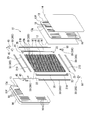
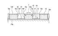
- FIG. 4 is a perspective developed view showing the configuration of the panel body in the present embodiment.
- FIG. 5 is a half cross-sectional view of an intermediate portion in the plate thickness direction of the panel body.
- FIG. 6 is a top view showing an end portion of the panel body.
- FIG. 7 is a cross-sectional view showing the structure of the straight portion of the panel body.
- FIG. 8 is a cross-sectional view showing the structure of the corner portion of the panel body.
- the panel body 11 includes a panel base material (base material) 12, a cushion material (soft material) 13 provided along both surfaces of the panel base material 12, the panel base material 12, and the cushion material. 13 and a fixing member 30 are provided.
- the panel body 11 has a flat plate shape, or a substantially L shape that is bent or curved at an intermediate portion when viewed in plan or side view, or a plan view that is curved as a whole. It can be C-shaped or the like. In the following description, it is assumed that the panel body 11 has a flat plate shape.
- the panel base 12 includes a panel-shaped core 15, a frame 20 provided along the outer periphery of the core 15, a base sheet 18 provided so as to cover both the core 15 and the frame 20, It has.
- the core material 15 is made of, for example, a paper material, a resin material, a wood material, or the like.
- the core material 15 is preferably as light as possible. Therefore, in the present embodiment, the core material 15 is formed of a paper-based material, and a large number of holes 15h penetrating in the thickness direction are arranged in parallel. For example, the holes 15h are combined in a plurality of staggered shapes with a hexagonal cross section. It has a honeycomb structure.
- a frame 20 is provided on the outer peripheral portion of the core member 15.
- the frame 20 includes frame members 21 ⁇ / b> A, 21 ⁇ / b> B, 21 ⁇ / b> C, and 21 ⁇ / b> D provided along the four sides of the core member 15.
- Each frame member 21A, 21B, 21D, 21D is formed of a metal-based material, a resin-based material, or the like.
- the frame members 21 ⁇ / b> A and 21 ⁇ / b> B extend in the vertical direction along two sides facing each other in the core member 15, and are provided on both sides in the width direction of the panel body 11.
- the frame members 21 ⁇ / b> C and 21 ⁇ / b> D extend in the horizontal direction perpendicular to the frame members 21 ⁇ / b> A and 21 ⁇ / b> B and are provided on both sides of the panel body 11 in the vertical direction.
- the frame members 21A, 21B and the frame members 21C, 21D are joined together by bolts 23, welding, adhesion, or the like via an L-shaped bracket 22.
- These frame members 21A, 21B, 21C, and 21D form a frame 20 having a rectangular shape as a whole.
- the frame members 21A, 21B, 21C, and 21D are respectively formed from a base portion 21e facing the outer peripheral end surface 15a of the core member 15 on the inner peripheral side of the frame 20, and from both sides in the width direction of the base portion 21e.
- Each of them is formed in a substantially U-shaped cross section including a side wall portion 21 f rising toward the outer peripheral side of the frame 20.
- a portion surrounded by the base portion 21e and the side wall portions 21f and 21f on both sides is formed as a groove 25.
- the panel base material 12 has a groove 25 which is continuous along the outer peripheral end portion thereof and is recessed toward the inside of the panel base material 12.
- the L-shaped bracket 22 is formed on the first plate portion 22a and the first plate portion 22a provided at the end of the frame member 21A or 21B along the frame member 21A or 21B.
- a second plate portion 22b that is perpendicular to the frame member 21C or 21D along the frame member 21C or 21D, and an L-shaped bracket 22 that extends along the first plate portion 22a and the second plate portion 22b.
- a rib portion 22c provided on the inner side in the bending direction is integrally formed.
- a female screw portion 29 is formed on the first plate portion 22 a and the second plate portion 22 b of the L-shaped bracket 22. Further, the base portion 21e of the frame member 21A or 21B along the first plate portion 22a of the bracket 22 and the base portion 21e of the frame member 21C or 21D along the second plate portion 22b are respectively at positions facing the female screw portion 29. A through hole 28 is formed. The female screw portion 29 and the through hole 28 are optional member attachment portions for attaching various optional members exemplified later.
- the rib portion 22c is formed so as to protrude from the first plate portion 22a and the second plate portion 22b toward the inner peripheral side of the panel body 11 perpendicular to the first plate portion 22a and the second plate portion 22b.
- This rib part 22c is formed in the width direction both sides of the 1st plate part 22a and the 2nd plate part 22b, ie, the one surface side and the other surface side of the panel body 11, respectively.
- the rib portion 22c not only functions as a reinforcing member that increases the bending strength of the first plate portion 22a and the second plate portion 22b, but can also function as a pressing member for a corner portion of the core material 15.
- the core material 15 is sandwiched between the rib portions 22c provided on the one surface side and the other surface side of the panel base material 12, respectively. That is, in the panel base material 12, the core material 15 can be held inside the frame 20 by providing such brackets 22 at the four corners.
- sheet-like base sheets 18 are provided on both surfaces of the core material 15 so as to cover the frame 20 and the core material 15.
- the base sheet 18 is made of, for example, cardboard.
- the base sheet 18 has an outer dimension larger than that of the core member 15, and an outer peripheral portion 18 a is bonded to the surface 20 f of the frame 20 with an adhesive or the like.
- the cushion material 13 is provided along the base sheet 18 that forms the surface of the panel substrate 12.
- the cushion material 13 is provided so as to cover the entire core material 15 via the base sheet 18.
- the cushion member 13 is provided so that the outer peripheral end portion 13 s covers the side wall portion 21 f of each frame member 21 A, 21 B, 21 C, 21 D constituting the frame 20. That is, the cushion material 13 is provided so as to cover the core material 15 and the frame 20.
- the cushion material 13 is formed of a material having flexibility and elasticity, such as a urethane foam material.
- FIG. 9A and 9B are cross-sectional views showing the cushion material 13 provided along the surface of the panel substrate 12, FIG. 9A is a cross-sectional view of the cushion material 13 in a state where the skin material 14 is not attached, and FIG. It is sectional drawing of the cushion material 13 in the state which mounted
- FIG. 4 As shown in FIG. 4, a plurality of through holes 16 are formed in the cushion material 13.
- the through hole 16 has, for example, an oval shape with the vertical direction as the major axis direction.
- a plurality of through holes 16 are arranged on the outer surface 13 f of the cushion material 13 at intervals in the vertical direction and the horizontal direction perpendicular to the vertical direction.
- each through-hole 16 cushions the cushion material 13 from the outer surface 13f facing the opposite side of the panel base material 12 to the opposing surface 13g facing the panel base material 12 side.
- the material 13 is formed so as to penetrate in the thickness direction.
- each through-hole 16 has an inner peripheral surface 16f formed perpendicular to the outer surface 13f. Thereby, a corner 16v is formed at the periphery of the through hole 16.
- the skin material 14 is provided so as to cover the entire cushion material 13.
- the skin material 14 extends along the outer surface 13 f of the cushion material 13, the inner peripheral surface 16 f orthogonal to the outer surface 13 f in the through hole 16, and the exposed surface 18 f of the base sheet 18 exposed at the bottom of the through hole 16. It is glued. In this manner, the skin material 14 extends along the plurality of through holes 16 formed in the cushion material 13, so that a plurality of oval (concave / convex portions) recesses 17 are formed on the surface of the panel body 11. ing.
- the skin material 14 is adhere
- the skin material 14 is formed of an elastically deformable material such as polyester, and covers the cushion material 13 and the panel base material 12 in an expanded state.
- a corner 16 v that protrudes outward at the periphery of the through hole 16 on the outer surface 13 f side is pressed inward by the skin material 14.
- the cushion material 13 is elastically deformed in the compression direction at the corner portion 16v, and the corner portion 16v of the through hole 16 has an arcuate cross section.
- the cushion material 13 and the skin material 14 have larger outer dimensions than the panel base material 12. And as for the cushion material 13 and the skin material 14, the outer peripheral edge parts 13e and 14e go around the outer-periphery edge part of the panel base material 12, ie, the side wall part 21f of each frame material 21A, 21B, 21C, 21D, and are grooved. 25 is caught inside.
- the cushion material 13 is compressed by the skin material 14 at the portion where the outer peripheral end portions 13e, 14e of the cushion material 13 and the skin material 14 wrap around the side wall portions 21f of the frame materials 21A, 21B, 21C, 21D. Thereby, the panel body 11 is formed so that the thickness becomes gradually thinner toward the outer peripheral end portion 11s.
- the panel body 11 is formed in a circular arc shape at a portion where the cushion material 13 and the skin material 14 wrap around the side wall portions 21f of the frame materials 21A, 21B, 21C, and 21D at the outer peripheral end portion 11s.
- the cushion material 13 and the skin material 14 constitute a skin structure.
- the fixing member 30 is fitted in the groove 25.
- the fixing member 30 sandwiches the outer peripheral end portions 13 e and 14 e of the cushion material 13 and the skin material 14 wound inside the groove 25 between the inner peripheral surface of the groove 25 and the outer peripheral surface of the fixing member 30.
- the outer peripheral end portions 13e and 14e of the cushion material 13 and the skin material 14 are fixed to the side wall portion 21f of the frame 20.
- the fixing member 30 includes a linear portion fixing member 30 ⁇ / b> S disposed on the linear portion 12 ⁇ / b> S of the outer peripheral portion of the rectangular panel base material 12 and an outer peripheral portion of the rectangular panel base material 12. And a corner portion fixing member 30C disposed at the corner portion 12C.
- the linear portion fixing member 30 ⁇ / b> S includes side plate portions 31, 31 whose cross-sectional shapes perpendicular to the direction in which the linear portion fixing member 30 ⁇ / b> S continues are positioned in parallel to each other, And a connecting plate portion 32 for connecting the 31 together.
- the side plate portions 31 and 31 sandwich the outer peripheral end portions 13e and 14e of the cushion material 13 and the skin material 14 between the side wall portions 21f forming the grooves 25 of the frame 20. For this reason, the interval between the side plate portions 31 and 31 is formed to be smaller than the interval between the side wall portions 21f and 21f of the groove 25 by a predetermined dimension.
- the side plate portions 31 and 31 are formed such that the tip portions 31 a and 31 a abut against the base portion 21 e of the groove 25 when the linear portion fixing member 30 ⁇ / b> S is fitted in the groove 25.
- the connecting plate portion 32 is formed so as to be offset in a direction away from the base portion 21e of the groove 25 with respect to the front end portions 31a, 31a of the side plate portions 31, 31.
- the straight part fixing member 30 ⁇ / b> S has a substantially H-shaped cross section by the side plate parts 31, 31 and the connecting plate part 32. Then, in a state where the linear portion fixing member 30 ⁇ / b> S is fitted in the groove 25, it is surrounded by the tip portions 31 a and 31 a side of the side plate portions 31 and 31, the connection plate portion 32, and the base portion 21 e of the groove 25.
- a space S1 is formed in the part.
- This space S1 is more than the portion of the cushion material 13 and the outer peripheral end portions 13e, 14e of the skin material 14 wound in the groove 25, that is, the portion of the outer peripheral end portions 13e, 14e that hits the base portion 21e of the frame 20. It functions as an accommodating space that can accommodate a tip portion (not shown).
- the linear portion fixing member 30 ⁇ / b> S prevents the cushion material 13 and the skin material 14 from coming out of the groove 25.
- protrusions 34, 34 projecting inward from the side plate portions 31, 31 are provided on the side farther from the base portion 21 e of the groove 25 than the connecting plate portion 32. Is formed.
- a holding groove 35 is formed as an optional member mounting portion surrounded by the protrusions 34, 34, the side plate portions 31, 31 and the connecting plate portion 32.
- the corner portion fixing member 30 ⁇ / b> C disposed at the upper corner portion of the panel body 11 is bent from the upper end of the first linear portion 38 ⁇ / b> A and the first linear portion 38 ⁇ / b> A in the lateral direction.
- a second linear portion 38B extending in a substantially L shape. 38 A of 1st linear parts are engage
- the second linear portion 38B is formed continuously from one end of the first linear portion 38A, and is fitted into the groove 25 at both ends of the frame member 21C or the frame member 21D extending in the lateral direction.
- the groove 25 is continuously formed on the upper surface and both side surfaces of the base material 21, and the corner portion fixing member 30 ⁇ / b> C is provided at a portion where the groove 25 on the upper surface and the groove 25 on both side surfaces are continuous. ing.
- the first linear portion 38 ⁇ / b> A and the second linear portion 38 ⁇ / b> B have side plate portions 36 and 36 in which the cross-sectional shapes orthogonal to the continuous direction are parallel to each other, and the side plate And a connecting plate portion 37 for connecting the portions 36 and 36 together.
- the side plate portions 36 and 36 sandwich the outer peripheral end portions 13e and 14e of the cushion material 13 and the skin material 14 between the side wall portions 21f and 21f forming the groove 25 of the frame 20. For this reason, the interval between the side plate portions 36 and 36 is formed to be smaller than the interval between the side wall portions 21 f and 21 f of the groove 25 by a predetermined dimension.
- the side plate portions 36 and 36 are formed such that the end portions 36 a and 36 a abut against the base portion 21 e of the groove 25 when the corner portion fixing member 30 ⁇ / b> C is fitted into the groove 25.
- convex portions 36 t and 36 t are formed on the side facing the side wall portions 21 f and 21 f of the groove 25.
- the convex portions 36t and 36t sandwich the outer peripheral end portions 13e and 14e of the cushion material 13 and the skin material 14 between the side plate portions 31 and 31 and the side wall portions 21f and 21f.
- the connecting plate portion 37 is formed so as to be offset in a direction away from the base portion 21e of the groove 25 with respect to the front end portions 36a, 36a of the side plate portions 36, 36. Accordingly, the corner portion fixing member 30 ⁇ / b> C has a substantially H-shaped cross section by the side plate portions 36 and 36 and the connecting plate portion 37.
- the linear portion fixing member 30S is surrounded by the distal end portions 36a, 36a of the side plate portions 36, 36, the connecting plate portion 37, and the base portion 21e of the groove 25 in a state where the linear portion fixing member 30S is fitted in the groove 25.
- a space S2 is formed in the part.
- This space S2 is more than the portion of the cushion material 13 and the outer peripheral end portions 13e, 14e of the skin material 14 wound in the groove 25, that is, the portion of the outer peripheral end portions 13e, 14e that hits the base portion 21e of the frame 20. It functions as an accommodating space that can accommodate a tip portion (not shown).
- the connecting plate portion 37 is closer to the base portion 21e than the connecting plate portion 32 in the linear portion fixing member 30S, and the space S2 is formed to be smaller than the space S1.
- the corner portion fixing member 30 ⁇ / b> C is fixed to the groove 25 by a corner cap 40.
- the corner cap 40 has a substantially L shape including a first linear portion 41A and a second linear portion 41B that is continuous with one end of the first linear portion 41A and extends orthogonally to the first linear portion 41A.
- the first linear portion 41A and the second linear portion 41B are side plate portions 36, 36 with respect to the first linear portion 38A and the second linear portion 38B of the corner fixing member 30C. And is abutted against the connecting plate portion 37.
- the protrusion piece 43 is formed in the lower end part of 41 A of 1st linear parts toward the downward direction. The protruding piece 43 is inserted into the holding groove 35 (see FIG. 7) between the connecting plate portion 32 and the protrusion 34 at the upper end portion of the linear portion fixing member 30S.
- a bolt insertion hole 44 for inserting a bolt 45 is formed in the second linear portion 41B.
- the corner cap 40, the corner portion fixing member 30C, the frame member 21C, and the second plate portion 22b of the bracket 22 are integrally fastened by the bolt 45 inserted through the bolt insertion hole 44.
- support legs 50 are provided at the corners of the lower ends of the panel body 11 as described above.
- the support leg 50 makes the panel body 11 stand on the floor surface by being grounded to the floor surface.
- the support leg 50 extends downward from one end of the lower support 51 and the lower support 51 accommodated in the groove 25 at the lower end 12P of the panel base 12, and the side lower end 12Q of the panel base 12.
- the side support portion 52 accommodated in the groove 25 and the support leg portion 53 extending downward from the lower support portion 51 are integrally provided.
- the lower support 51 is abutted against and fixed to a base 21 e that forms the bottom surface of the groove 25 at the lower end of the frame 20.
- the side portion support portion 52 is fixed in contact with a base portion 21 e that forms the bottom surface of the groove 25 at the side end portion of the frame 20.
- Bolt insertion holes 54 through which the bolts 48 are inserted are formed in the lower support portion 51 and the side support portions 52. The bolt 48 inserted into the bolt insertion hole 54 is screwed into the female screw portion 29 and the through hole 28. As a result, the support leg 50 is fixed to the panel body 11.
- the support leg portion 53 extends below the lower support portion 51, and a height adjusting screw 49 can be screwed into a lower end portion thereof.
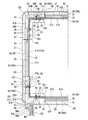
- FIG. 10 is a side view of the connecting portion of the panel body 11 with respect to the upper part of the backrest plate 108 of the sofa.
- FIG. 11 is a cross-sectional view showing the structure of the connecting portion between the sofa 101 and the panel body 11.
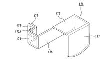
- FIG. 12 is a perspective view of the fixture upper connection bracket 171 that connects the sofa 101 and the panel body 11.
- FIG. 13 is a perspective view of the lower fixture connecting bracket 181 that connects the sofa 101 and the panel body 11.
- an upper fixture bracket 171 that connects the panel body 11 and the upper portion of the sofa 101 can be attached to the upper portion of the panel body 11.
- the fixture upper connection bracket 171 is a locking portion 172 attached to the end in the width direction of the panel body 11, and is bent from the end of the locking portion 172, and is a linear portion fixing member 30 ⁇ / b> S provided in the groove 25 of the panel body 11.
- Side wall portion 173 extending along side plate portion 31.
- the fixture upper connection bracket 171 is bent from the end portion of the side wall portion 173 and extends along the outer peripheral end portion 11 s of the panel body 11, and is bent from the end portion of the outer wall portion 174 to be attached to the skin material 14 of the panel body 11. And a sandwiching wall portion 175 disposed along.
- the upper fixture connecting bracket 171 includes an upper wall portion 176 disposed along the upper end of the backrest plate 108 of the sofa 101, and a front wall disposed along the front surface of the backrest plate 108 from the end portion of the upper wall portion 176. Part 177.
- a through hole 172A is formed in the locking portion 172 of the fixture upper connection bracket 171.
- a base portion in which a bolt 179 inserted through the through hole 172A is provided in the holding groove 35 of the linear portion fixing member 30S fixed to the frame member 21A (or the frame member 21B) of the panel body 11, and a female screw is formed. 178 is screwed together. With the fixture upper connection bracket 171 attached to the panel body 11 in this manner, the upper portion of the backrest plate 108 of the sofa 101 is held between the holding wall portion 175 and the front wall portion 177 of the fixture upper connection bracket 171. .
- the cushion material 13P on the panel body 11 on the side where the outer wall portion 174 of the fixture upper connection bracket 171 is arranged is pressed by the outer wall portion 174.
- the width dimension of the cushion material 13P on the side where the fixture connection bracket 171 is arranged is shorter than the width dimension of the cushion material 13Q on the side where the fixture connection bracket 171 is not arranged.
- the end portion of the cushion material 13Q and the end surface of the outer wall portion 174 of the fixture connection bracket 171 disposed along the cushion material 13P are flush with each other.
- the upper part of the sofa 101 and the lower part of the panel body 11 are connected via a fixture lower connection bracket 181.
- the fixture lower connection bracket 181 includes a support wall portion 182 fixed to the base plate 105 of the leg portion 103 attached to the lower surface of the seat surface portion 102 of the sofa 101 with a bolt (not shown), and downward from the end portion of the support wall portion 182. And a bent wall portion 183 formed to be bent.
- the fixture lower connection bracket 181 is bent from the end of the bent wall portion 183 and is bent from the upper and lower wall portions 184 arranged along the skin material 14 of the panel body 11 and the lower end of the upper and lower wall portion 184 to the panel body 11 side.
- a lower wall portion 185 extending toward the upper side and a locking portion 186 extending upward from an end portion of the lower wall portion 185 are provided.
- a rib 186 ⁇ / b> A having a width corresponding to the distance between the side plate portions 31, 31 of the linear portion fixing member 30 ⁇ / b> S at the lower end portion of the panel body 11 is formed in the locking portion 186.
- the locking portion 186 of the lower fixture bracket 181 is inserted and locked between the side plate portions 31 and 31 of the linear portion fixing member 30S at the lower end portion of the panel body 11.
- the panel body 11 is attached to the back surface of the backrest plate 108 via the fixture upper connection bracket 171 and the fixture lower connection bracket 181.
- the sofas 101 and 101 adjacent to each other are connected to all the leg portions 103 and 103 of the sofa 101 and the panel bodies 11 and 11 as follows. ing.
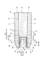
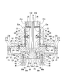
- FIG. 14 is a perspective view showing an example of a connection structure in the support leg 50 provided at the lower corner of the panel body 11.
- FIG. 15 is a cross-sectional view showing a connection structure at the lower part of the panel bodies 11 and 11.
- the support leg 50 is integrally formed with a bulging portion 56 bulging downward from the lower support portion 51.
- a slit 57 into which one end of the plate-like lower connecting member 55 can be inserted is formed in an intermediate portion of the support leg 50 along the thickness direction of the panel body 11.
- the slit 57 is open to the side surface 56 a and the lower surface 56 b on the side adjacent to the other panel body 11 in the bulging portion 56.
- an insertion recess 57 a into which a projection 58 ⁇ / b> A of a lower connecting member 55 described later is inserted is formed in the upper part of the slit 57 so as to be recessed upward.
- a protruding portion 57b that protrudes downward is formed adjacent to the insertion concave portion 57a.
- the bulging portion 56 is formed with a locking hole 56 h for locking the lower connecting member 55 inserted in the slit 57, penetrating along the thickness direction of the panel body 11. .
- the lower connecting member 55 has through holes 55h at both ends.
- protrusions 58A that protrude upward are formed at both ends of the lower connecting member 55, respectively.
- the lower connecting member 55 is formed with a central protrusion 58B protruding upward between the protrusions 58A and 58A at both ends.
- An engagement recess 58C that is recessed downward is formed between the central protrusion 58B and the protrusions 58A on both sides thereof.
- the protruding portion 57b and the engaging recess 58C are formed as vertical surfaces 57f and 58f extending in the vertical direction on the side surface 56a side and the central protruding portion 58B side of the bulging portion 56, and as the opposite side goes upward, the vertical surface 57f, The inclined surfaces 57g and 58g are separated from 58f.
- the protrusion 57b and the engagement recess 58C both have a tapered shape in which the width dimension gradually decreases as going downward.
- both end portions of the lower connecting member 55 in which the through holes 55h are formed are inserted into the slits 57 of the support leg 50.
- the protrusions 57b of the support legs 50 provided on the panel bodies 11 on both sides are fitted into the engagement recesses 58C at both ends of the lower connecting member 55, respectively.
- the projecting portion 57b and the engaging recess 58C both have a tapered shape in which the width dimension gradually decreases as going downward. Therefore, the protrusion 57b is inserted into the engaging recess 58C, whereby the lower connecting member 55 and the support leg 50 are positioned with respect to each other in the direction in which the panel bodies 11 and 11 are adjacent to each other.
- FIG. 16 is a perspective view showing an example of a connection structure in the upper part of the panel bodies 11 and 11.
- the panel bodies 11 and 11 adjacent to each other can be connected to each other by upper connection members 61 as optional members.
- the upper connecting member 61 is attached to the corner portion fixing member 30C instead of the corner cap 40.
- Bolt insertion holes 62 are formed in both end portions 61 a and 61 a of the upper connecting member 61.
- the corner portion fixing members 30C are formed in both end portions 61 a and 61 a of the upper connecting member 61.
- the corner portion fixing members 30C are formed in both end portions 61 a and 61 a of the upper connecting member 61.
- An interval regulating portion 63 that regulates the interval of 30C is formed to protrude downward.
- the corner restricting members 30C.. Are disposed at the upper portions of the panel bodies 11 and 11 adjacent to each other. By inserting between 30C, the space
- the upper connecting member 61 is connected to the corner portion fixing members 30C. Place on 30C. At this time, the lower surfaces of both end portions 61a and 61a of the upper connecting member 61 are inserted between the side plate portions 36 and 36 with respect to the second linear portion 38B of the corner portion fixing member 30C, and the connecting plate portion 37 is inserted. Has been hit. And the space
- the connecting plate portion 37 of the first linear portion 38A of the corner portion fixing member 30C is abutted against both side surfaces 63a and 63a of the interval restricting portion 63 so that the interval between the panel bodies 11 and 11 is appropriate. Can be positioned.
- the bolt 64 inserted through the bolt insertion hole 62 is fastened to the female screw portion 29 through the through hole 28, whereby the upper connecting member 61, the corner portion fixing member 30C, and the frame member 21C (see FIG. 5).
- the second plate portion 22b (see FIG. 5) of the bracket 22 is fixed integrally. As a result, the upper ends of the panel bodies 11 and 11 adjacent to each other are connected to each other.
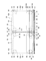
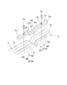
- FIG. 17 is a front view showing a connecting portion between the leg portions 103 and 103 in the front portions of the sofas 101 and 101 adjacent to each other.
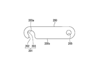
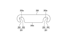
- FIG. 18 is a plan view showing the connecting plate 200.
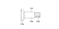
- FIG. 19 is a side view showing the engaging member 210.
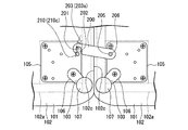
- 20A and 20B are diagrams illustrating a flow when the leg portions 103 and 103 of the sofas 101 and 101 adjacent to each other are coupled to each other, and FIG. 20A is a diagram illustrating a state before the coupling plate 200 is rotated; FIG. 20B is a diagram illustrating a state immediately before the coupling portion 201 of the coupling plate 200 is engaged with the engagement member 210.
- FIG. 20A is a diagram illustrating a state before the coupling plate 200 is rotated;
- FIG. 20B is a diagram illustrating a state immediately before the coupling portion 201 of the coupling plate 200 is engaged with the engagement member 210.
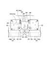
- FIG. 21 is a diagram illustrating a state in which the sofas 101 are connected to each other by engaging the connecting portion 201 of the connecting plate 200 with the engaging member 210.
- the sofas 101, 101 adjacent to each other are connected to the leg portions 103, 103 provided on the front end side of the seating surface portion 102 by the connecting plate 200.
- the connecting plate 200 is formed from an oval metal plate.
- the connection plate 200 includes a connection part 201 and a connection hole (connection part) 205 as connection parts connected to the respective sofas 101 at both ends.
- the connecting portion 201 is formed at one end of the connecting plate 200 and is connected to one sofa 101.
- the connection hole 205 is formed through the other end of the connection plate 200 and is rotatably connected to the other sofa 101.
- the connection portion 201 includes an insertion portion 202 that opens to a side 200 s extending in the longitudinal direction of the connection plate 200, and an engagement portion 203 that is formed continuously with the insertion portion 202.
- the insertion portion 202 has an opening width larger than the outer diameter of a shaft portion 210c (see FIG.
- the insertion portion 202 extends from the side 200 s of the connection plate 200 along the short direction of the connection plate 200.
- the engaging portion 203 is formed at the center in the short direction of the connecting plate 200.
- the engaging part 203 has a larger inner diameter than the shaft part 210 c of the engaging member 210.
- the engaging portion 203 is formed offset with respect to the insertion portion 202 on the side away from the connecting hole 205. As a result, the engagement portion 203 is formed with an engagement recess 203 a that expands toward the side away from the connection hole 205 with respect to the insertion portion 202.
- the connecting plate 200 has an in-plane surface along the lower surface 102 f of the seat surface portion 102 around the screw 206 by fastening a screw 206 passed through the connecting hole 205 to the base plate 105 of the leg portion 103. It can be rotated freely.
- the engagement member 210 is formed of a so-called stepped screw, a screw head 210 a provided on one end side, a male screw portion 210 b provided on the other end side, and a screw head 210 a
- the shaft portion 210c is formed between the male screw portion 210b and has an outer diameter larger than that of the male screw portion 210b.
- a male screw portion 210 b is screwed into the base plate 105 of the leg portion 103 provided on the lower surface of the seat surface portion 102 of the sofa 101.
- the shaft portion 210c of the engaging member 210 abuts against the base plate 105, and the screw head portion 210a is positioned below the base plate 105 with an interval corresponding to the axial length of the shaft portion 210c.
- the shaft portions (displacement allowing portions) 210 c of the engaging member 210 enter the inserting portion 202 of the connecting portion 201 and engage with the engaging portion 203, so that the sofas 101, 101 adjacent to each other are connected.
- Link
- the engagement member 210 can be inserted in a state where the cushion portion 102c is compressed and deformed in a direction in which the two adjacent sofas 101 and 101 are brought close to each other. .
- the connecting member 200 in order to connect the two sofas 101 and 101 adjacent to each other by the connecting plate 200, the connecting member 200 is centered on the screw 206 as shown in FIGS. 20A and 20B.
- the shaft part 210c of the engaging member 210 is received in the connecting part 201 by rotating.
- the insertion portion 202 of the connecting portion 201 interferes with the shaft portion 210c of the engaging member 210 as shown in FIG. 20B. Therefore, as shown in FIG. 21, the cushion portion 102c is compressed and deformed in a direction in which the two sofas 101, 101 adjacent to each other are brought close to each other.
- the two sofas 101 adjacent to each other may be pushed in a direction to bring them close to each other.
- the engaging member 210 can be inserted into the engaging portion 203 through the insertion portion 202 of the connecting portion 201 at one end of the connecting plate 200.
- the press between sofas 101 and 101 is cancelled
- the cushion portion 102c is deformed in a restoring direction by the repulsive force of the cushion portion 102c that has been compressed and deformed.
- the engagement member 210 engages with the engagement recess 203 a of the engagement portion 203 of the connecting portion 201.
- the engaging state with respect to the sofa 101 is maintained in the connecting portion 201 on one end side of the connecting plate 200. In this way, the two sofas 101 adjacent to each other are connected to each other.
- the two sofas 101 and 101 adjacent to each other are pushed in a direction to approach each other, and the cushion portion 102c is compressed and deformed.
- the shaft portion 210 c of the engaging member 210 is displaced from the state where the shaft portion 210 c enters the engaging recess 203 a of the engaging portion 203 and is engaged with the inserting portion 202.
- the connecting plate 200 is rotated about the connecting hole 205, the shaft portion 210 c of the engaging member 210 comes out of the insertion portion 202. In this way, the connecting portion 201 at one end of the connecting plate 200 can be detached from the sofa 101.
- the axial length of the shaft portion 210 c of the engaging member 210 is set to be greater than the plate thickness of the connecting plate 200.
- the sofas 101 and 101 adjacent to each other are connected by the connection plate 200.
- the connecting portion 201 at one end of the connecting plate 200 can be engaged / disengaged with the sofa 101 in a state in which the cushion portion 102c is compressed and deformed in a direction in which the two sofas 101, 101 adjacent to each other are brought close to each other.
- the engaged state with respect to the sofa 101 is maintained in a state in which the compressed and deformed cushion portion 102c is deformed in a restoring direction.
- the cushion part 102c is compressed and deformed by pushing the two sofas 101 and 101 adjacent to each other in the approaching direction, so that the connection part 201 of the connection plate 200 is compressed. Can be detached from the sofa 101. In this way, the sofas 101 and 101 can be easily and reliably connected to each other to prevent the position of the sofa 101 from being displaced.
- an engaging member 210 that engages the connecting plate 200 is provided on one of the sofas 101 adjacent to each other, and the connecting part 201 has a cushion part 102c in a direction in which the two sofas 101, 101 adjacent to each other are brought close to each other.
- an engaging portion 203 to be engaged is provided on one of the sofas 101 adjacent to each other, and the connecting part 201 has a cushion part 102c in a direction in which the two sofas 101, 101 adjacent to each other are brought close to each other.
- the engagement member 210 is inserted into the insertion portion 202 in a state in which the cushion portion 102c is compressed and deformed in a direction in which the two sofas 101, 101 adjacent to each other approach each other. 201 can be engaged and disengaged with respect to the sofa 101. Further, when the cushion portion 102c which has been compressed and deformed is deformed in the restoring direction, the engaging member 210 is engaged with the engaging portion 203 which is expanded more in the direction in which the cushion portion 102c is restored than the insertion portion 202. Thereby, the engagement state with respect to the sofa 101 is maintained.
- connection hole 205 at the other end of the connection plate 200 is rotatably connected to the other of the sofas 101 adjacent to each other.
- the connection plate 200 is connected to the other of the sofas 101 adjacent to each other, so that it is not necessary to prepare the connection plate 200 separately.
- the engaging member 210 has a shaft portion 210c having a certain length in the vertical direction, and the engaging plate 210 is engaged with the shaft portion 210c in a state in which the connecting plate 200 can be displaced in the height direction of the sofa 101. Match. With this configuration, the sofas 101 and 101 can be connected to each other by the connecting plate 200 even when the adjacent sofas 101 and 101 have different height levels due to unevenness of the floor surface.
- the sofa 101 includes a seat surface portion 102 and leg portions 103 that stand on the floor surface, and the connecting plate 200 is provided on the lower surface of the seat surface portion 102.
- the connecting plate 200 is provided on the lower surface of the seat surface portion 102.
- the connecting plate 200 is disposed at the base of the leg 103.
- the sofas 101 and 101 adjacent to each other can be brought close to each other by grasping both leg portions 103 and 103. Therefore, the sofa 101 and 101 can be easily connected by the connection plate 200.
- the seating surface portions 102 and 102 of the sofas 101 and 101 adjacent to each other are connected by the connection plate 200 in a state where the cushion portions 102c and 102c are pressed against each other.
- the seating surface portions 102 and 102 can be brought into close contact with each other without shifting and the appearance can be improved.
- the seat surface portions 102 and 102 are in close contact with each other, it is possible to prevent articles and the like from falling into the gap between the seat surface portions 102 and 102.
- the panel bodies 11 and 11 mounted on the backrest plates 108 and 108 are connected between the sofas 101 and 101 adjacent to each other.
- sofa 101,101 can be connected in a rear part.
- the skin material 14 that covers the panel base material 12 and the cushion material 13 wraps around the outer peripheral edge portion of the panel base material 12 in the outer peripheral portion of the panel body 11 to form the groove 25. It is caught inside. For this reason, the outer peripheral part of the panel body 11 is covered with the skin material 14 without the panel base material 12 being exposed. Furthermore, since the skin material 14 is fixed by the fixing member 30 in the groove 25, the fixing member 30 can be prevented from being exposed to the outer peripheral portion of the panel body 11. Thereby, the external appearance of the panel body 11 can be made into a flexible and organic impression.
- connection plate 200 forms the connecting part 201 at one end and the connecting hole 205 at the other end, but is not limited thereto.
- connecting portions 201 may be formed at both ends of the connecting plate 200.
- connection part 201 of the connection plate 200 was engaged with the engagement member 210, the engagement member 210 may be what kind of structure.
- the connecting plate 200 is engaged with the shaft portion 210c having a certain length in the vertical direction so as to be displaceable in the height direction of the sofa 101, but is not limited thereto.
- the shaft portion 210 c may have a thickness equivalent to the plate thickness of the connection plate 200.
- the connecting portion 201 of the connecting plate 200 may be engaged with the support leg 106 itself of the leg portion 103. .
- the panel bodies 11 and 11 are connected to each other by the upper connecting member 61 and the lower connecting member 55, but the present invention is not limited to this.
- the panel bodies 11 may not be connected to each other, and the sofas 101 and 101 adjacent to each other may be connected to each other by the connection plate 200 in the leg 103 at the rear part of the sofa 101 in the same manner as the front part of the sofa.
- the lower connecting member 55 that connects the panel bodies 11 and 11, as in the connecting plate 200 is in the direction in which the two adjacent panel bodies 11 and 11 approach each other at least at one end.
- the connection bolt 59 of the panel body 11 can be engaged and disengaged, and in the state where the compressed and deformed cushion material 13 is deformed in the restoring direction, the connection bolt of the panel body 11 is restored.
- the connection part 201 with which the engagement state with respect to 59 is maintained may be provided.
- the sofa 101 may have any configuration.
- the backrest portion 104 includes the backrest plate 108 and the backrest cushion 109, and the panel body 11 is attached to the backrest plate 108.
- the present invention is not limited to this.
- the panel body 11 and the backrest cushion 109 may not be provided, and a backrest portion extending upward from the rear end portion of the seat surface portion 102 may be formed integrally with the seat surface portion 102.
- the panel body 11 may have any configuration.
- the panel base material 12 was formed from the core material 15, the frame 20, and the base sheet 18, it is not restricted to this.
- a panel made of a resin material or the like may be used as the panel substrate 12 as it is.
- the cushion material 13 and the skin material 14 are provided in the said embodiment, the cushion material 13 and the skin material 14 are not essential structures.
- the sofa system 100 which connects sofas 101 and 101 was mentioned as an example, it is not restricted to this.
- the same configuration can be applied to the portion connecting the sofa 101 and other furniture such as a side table and a cabinet.
- the present invention can be similarly applied as long as the furniture is connected.
- the configuration described in the above embodiment can be selected or changed to another configuration as appropriate without departing from the gist of the present invention.
- furniture can be easily and reliably connected to each other, and the displacement of the furniture can be prevented.
Landscapes
- Health & Medical Sciences (AREA)
- General Health & Medical Sciences (AREA)
- Dentistry (AREA)
- Connection Of Plates (AREA)
- Chairs For Special Purposes, Such As Reclining Chairs (AREA)
- Combinations Of Kitchen Furniture (AREA)
- Nursing (AREA)
Abstract
家具システムは、互いに隣接配置される複数の家具(101)と、複数の家具(101)どうしを連結する連結プレート(200)と、を備え、互いに隣接する二つの家具(101)の少なくとも一方は、隣接する他の家具(101)に対向する外側面に弾性変形可能なクッション部(102c)を有し、連結プレート(200)は、両端部に、それぞれの家具(101)に連結される連結部(201、205)を有し、連結プレート(200)において少なくとも一端部の連結部(201)は、互いに隣接する二つの家具どうし(101)を接近させる方向にクッション部(102c)を圧縮変形させた状態で家具(101)に係合・離脱可能とされ、圧縮変形したクッション部(102c)が復元する方向に変形した状態で、家具(101)に対する係合状態が維持される。
Description
本発明は、ソファ等の家具を複数備える家具システムに関する。
本願は、2014年1月31日に、日本に出願された特願2014-017383号に基づき優先権を主張し、その内容をここに援用する。
本願は、2014年1月31日に、日本に出願された特願2014-017383号に基づき優先権を主張し、その内容をここに援用する。
ソファ等の家具は、複数個を並べて床上に設置することがある(例えば特許文献1参照)。また、ソファに隣接してテーブルやキャビネットを設置する場合等、複数種の家具を並べて設置することもある。
例えば、ソファの場合、表面が柔軟なクッションで覆われている。このようなソファは、利用者が着座すると、クッションが上方から押圧されるにともなってクッションが外側に膨らむように変形する。すると、ソファに隣接して他のソファや家具を隙間なく設置した場合、外側に膨らんだクッションによって、隣接する他のソファや家具が横方向に押され、位置がずれてしまうことがある。
例えば、ソファの場合、表面が柔軟なクッションで覆われている。このようなソファは、利用者が着座すると、クッションが上方から押圧されるにともなってクッションが外側に膨らむように変形する。すると、ソファに隣接して他のソファや家具を隙間なく設置した場合、外側に膨らんだクッションによって、隣接する他のソファや家具が横方向に押され、位置がずれてしまうことがある。
そこで、ソファの着座部下面にプレートを設けておき、このプレートに連結金具をボルト留めすることによって、ソファと他のソファや家具を連結する方法が用いられている。
また、特許文献1には、一方のソファに帯板状の連結部材を設け、他方のソファに連結部材が係止される被連結部材が設けられた構成が開示されている。
また、特許文献1には、一方のソファに帯板状の連結部材を設け、他方のソファに連結部材が係止される被連結部材が設けられた構成が開示されている。
しかしながら、連結金具をボルト留めするには手間がかかる。
さらに、ソファ等の家具は、着座部下面の下方に十分な隙間があるとは限らず、着座部下面に連結金具をボルト留めしにくいことがある。ソファ等の家具を横倒しにしたり上下を反転させれば、ボルト留め作業を行いやすくなる。しかし、家具が重い場合や、上下を反転させると家具が傷ついたり壊れる可能性がある場合には、家具を横出しにしたり上下を反転させるのが困難である。
また、特許文献1のように、連結部材を被連結部材に係止したのみでは、ソファの位置がずれた場合に、連結部材の被連結部材への係止が解除されてしまう可能性がある。
そこで、本発明の目的は、家具どうしを容易かつ確実に連結し、家具の位置ずれを防ぐことができる家具システムを提供することである。
本発明は、上記課題を解決するため、以下の手段を採用する。
この発明に係る家具システムは、互いに隣接配置される複数の家具と、複数の家具どうしを連結する連結部材と、を備え、互いに隣接する二つの家具の少なくとも一方は、隣接する他の家具に対向する外側面に弾性変形可能なクッション部を有し、連結部材は、両端部に、それぞれの家具に連結される連結部を有し、連結部材において少なくとも一端部の連結部は、互いに隣接する二つの家具どうしを接近させる方向にクッション部を圧縮変形させた状態で家具に係合・離脱可能とされ、圧縮変形したクッション部が復元する方向に変形した状態で、家具に対する係合状態が維持される。
この発明に係る家具システムは、互いに隣接配置される複数の家具と、複数の家具どうしを連結する連結部材と、を備え、互いに隣接する二つの家具の少なくとも一方は、隣接する他の家具に対向する外側面に弾性変形可能なクッション部を有し、連結部材は、両端部に、それぞれの家具に連結される連結部を有し、連結部材において少なくとも一端部の連結部は、互いに隣接する二つの家具どうしを接近させる方向にクッション部を圧縮変形させた状態で家具に係合・離脱可能とされ、圧縮変形したクッション部が復元する方向に変形した状態で、家具に対する係合状態が維持される。
このような家具システムにおいては、互いに隣接する二つの家具どうしを連結部材によって連結させるには、互いに隣接する二つの家具どうしを接近させる方向に押してクッション部を圧縮変形させる。すると、連結部材の少なくとも一端部の連結部を、家具に対して係合させることができる。
このようにして連結部材の連結部を家具に対して係合させた後、家具どうしの押圧を解除する。すると、圧縮変形したクッション部が復元する方向に変形する。その結果、連結部の家具に対する係合状態が維持される。これにより、二つの家具どうしが連結される。
また、二つの家具どうしの連結を解除するには、互いに隣接する二つの家具どうしを接近させる方向に押してクッション部を圧縮変形させる。すると、連結部材の少なくとも一端部の連結部を、家具に対して離脱させることができる。
このようにして、ボルト締結作業を行うことなく、家具どうしを連結することができる。
このようにして連結部材の連結部を家具に対して係合させた後、家具どうしの押圧を解除する。すると、圧縮変形したクッション部が復元する方向に変形する。その結果、連結部の家具に対する係合状態が維持される。これにより、二つの家具どうしが連結される。
また、二つの家具どうしの連結を解除するには、互いに隣接する二つの家具どうしを接近させる方向に押してクッション部を圧縮変形させる。すると、連結部材の少なくとも一端部の連結部を、家具に対して離脱させることができる。
このようにして、ボルト締結作業を行うことなく、家具どうしを連結することができる。
また、互いに隣接する家具の一方に、連結部材が係合する係合部材が設けられ、連結部は、互いに隣接する二つの家具どうしを接近させる方向にクッション部を圧縮変形させた状態で係合部材が挿入される挿入部と、挿入部に連続して形成され、挿入部に対して家具どうしが離間する方向に拡開し、係合部材が係合する係合部と、を備えていてもよい。
このように構成することで、互いに隣接する二つの家具どうしを接近させる方向にクッション部を圧縮変形させた状態で、係合部材が挿入部に挿入可能となる。これにより、連結部材は家具に対して係合・離脱可能とされる。
また、圧縮変形したクッション部が復元する方向に変形すると、係合部材が、挿入部よりも家具どうしが離間する方向に拡開した係合部に係合する。これにより、連結部材は、家具に対する係合状態を維持する。
このように構成することで、互いに隣接する二つの家具どうしを接近させる方向にクッション部を圧縮変形させた状態で、係合部材が挿入部に挿入可能となる。これにより、連結部材は家具に対して係合・離脱可能とされる。
また、圧縮変形したクッション部が復元する方向に変形すると、係合部材が、挿入部よりも家具どうしが離間する方向に拡開した係合部に係合する。これにより、連結部材は、家具に対する係合状態を維持する。
また、連結部材の他端部が、互いに隣接する家具の他方に回動自在に連結されていてもよい。
このように構成することで、連結部材を回動させることによって、互いに隣接する二つの家具どうしを容易に連結できる。
また、家具どうしの連結を解除した状態でも、連結部材は、互いに隣接する家具の他方に連結されているため、連結部材を別途用意する必要がない。
このように構成することで、連結部材を回動させることによって、互いに隣接する二つの家具どうしを容易に連結できる。
また、家具どうしの連結を解除した状態でも、連結部材は、互いに隣接する家具の他方に連結されているため、連結部材を別途用意する必要がない。
また、係合部材は、連結部材が家具の高さ方向に変位可能な状態で係合する変位許容部を有していてもよい。
このように構成することで、床面の不陸等によって、互いに隣接する家具どうしの高さレベルが異なる場合でも、連結部材によって家具どうしを連結できる。
このように構成することで、床面の不陸等によって、互いに隣接する家具どうしの高さレベルが異なる場合でも、連結部材によって家具どうしを連結できる。
また、家具は、家具本体と、家具本体を床面上に立脚する脚部と、を備え、連結部材は、家具本体の下面に配置されていてもよい。
このように構成することで、脚部に支持された家具本体の下方には、床面との間に隙間が存在する。したがって、連結部材による家具どうしの連結作業を、家具本体と床面との隙間に手を入れて容易に行うことができる。
このように構成することで、脚部に支持された家具本体の下方には、床面との間に隙間が存在する。したがって、連結部材による家具どうしの連結作業を、家具本体と床面との隙間に手を入れて容易に行うことができる。
また、連結部材は、脚部の基部に配置されていてもよい。
これにより、互いに隣接する家具どうしを、双方の脚部を掴むことによって接近させることができる。したがって、連結部材による家具どうしの連結作業を容易に行うことができる。
これにより、互いに隣接する家具どうしを、双方の脚部を掴むことによって接近させることができる。したがって、連結部材による家具どうしの連結作業を容易に行うことができる。
また、互いに隣接する家具の少なくとも一方がソファであってもよい。
これにより、外側面がクッション部を有したソファを、他のソファや他の家具と容易かつ確実に連結することが可能となる。
これにより、外側面がクッション部を有したソファを、他のソファや他の家具と容易かつ確実に連結することが可能となる。
この発明に係る家具システムによれば、家具どうしを容易かつ確実に連結し、家具の位置ずれを防ぐことができる。
以下、添付図面を参照して、本発明による家具システムを実施するための形態を説明する。
図1は、本実施形態に係るソファシステムを示す正面図である。図2は、ソファシステムを示す底面図である。図3は、ソファシステムを構成するソファの側面図である。
図1~図3に示すように、ソファシステム(家具システム)100は、互いに隣接配置される複数のソファ(家具)101と、互いに隣接するソファ101どうしを連結する連結プレート(連結部材)200と、を備えている。
図1は、本実施形態に係るソファシステムを示す正面図である。図2は、ソファシステムを示す底面図である。図3は、ソファシステムを構成するソファの側面図である。
図1~図3に示すように、ソファシステム(家具システム)100は、互いに隣接配置される複数のソファ(家具)101と、互いに隣接するソファ101どうしを連結する連結プレート(連結部材)200と、を備えている。
(ソファ)
各ソファ101、使用者が着座する座面部(家具本体)102と、座面部102を支持する脚部103と、座面部102の一端側に設けられた背凭れ部104と、を備えている。
各ソファ101、使用者が着座する座面部(家具本体)102と、座面部102を支持する脚部103と、座面部102の一端側に設けられた背凭れ部104と、を備えている。
座面部102は、座面部102の下部において平面視矩形に組まれたフレーム102aと、フレーム102aを覆うように設けられ、例えば平面視略正方形状をなす直方体に形成されたクッション部102cと、を備えている。ここで、クッション部102cは、フレーム102aの周囲四方の外側面を覆うように設けられている。クッション部102cは、ウレタンフォーム等、弾性変形可能な材料からなり、表皮材等によって覆われている。
脚部103は、座面部102の下面の四隅にそれぞれ設けられている。脚部103は、座面部102の下面に固定されたベースプレート105と、ベースプレート105から下方に向けて延びる支持脚106と、支持脚106の下端部に設けられた高さレベル調整用のアジャスタ107と、を備えている。
背凭れ部104は、ソファ101の後部に設けられた背凭れ板108と、座面部102上に配置された背凭れクッション109と、を備えている。
背凭れ板108は、座面部102の背面に一体に固定されている。
背凭れクッション109は、座面部102や背凭れ板108に固定されていてもよいし、単に座面部102上に載置されていてもよい。
また、背凭れ板108の背面にはパネル体11が装着されている。
背凭れ板108は、座面部102の背面に一体に固定されている。
背凭れクッション109は、座面部102や背凭れ板108に固定されていてもよいし、単に座面部102上に載置されていてもよい。
また、背凭れ板108の背面にはパネル体11が装着されている。
(パネル体)
図4は、本実施形態におけるパネル体の構成を示す斜視展開図である。図5は、パネル体の板厚方向中間部における半断面図である。図6は、パネル体の端部を示す上面図である。図7は、パネル体の直線部の構造を示す断面図である。図8は、パネル体のコーナー部の構造を示す断面図である。
図4に示すように、パネル体11は、パネル基材(基材)12と、パネル基材12の両面に沿って設けられたクッション材(軟性材)13と、パネル基材12およびクッション材13を覆う表皮材14と、固定部材30と、を備えている。
パネル体11は、設置する什器の形状等に沿って、平面板状、あるいは平面視または側面視したときに、中間部で折曲または湾曲した略L字状、あるいは全体が湾曲した平面視略C字状等とすることができる。以下においては、パネル体11が平面板状であるとして説明を行う。
(パネル基材)
パネル基材12は、パネル状の芯材15と、芯材15の外周部に沿って設けられたフレーム20と、芯材15およびフレーム20の両面を覆うように設けられたベースシート18と、を備えている。
パネル基材12は、パネル状の芯材15と、芯材15の外周部に沿って設けられたフレーム20と、芯材15およびフレーム20の両面を覆うように設けられたベースシート18と、を備えている。
芯材15は、例えば紙系材料、樹脂系材料、木質系材料等から形成されている。この芯材15は、なるべく軽量とするのが好ましい。そこで、本実施形態では、芯材15は、紙系材料から形成され、板厚方向に貫通する孔15hが多数並設された、例えば孔15hが断面を六角形状として複数千鳥状に組み合わされたハニカム構造とされている。
(フレーム)
図4、図5に示すように、この芯材15の外周部には、フレーム20が設けられている。フレーム20は、芯材15の四辺に沿って設けられた枠材21A,21B,21C,21Dを備えている。各枠材21A,21B,21D,21Dは、金属系材料、樹脂系材料等から形成されている。
枠材21A,21Bは、芯材15において互いに対向する2辺に沿って上下方向に延び、パネル体11の幅方向両側に設けられている。枠材21C,21Dは、枠材21A,21Bに直交して横方向に延び、パネル体11の上下方向両側に設けられている。これら枠材21A,21Bと枠材21C,21Dとは、L字状のブラケット22を介し、ボルト23、あるいは溶接、接着等によって接合されている。これら枠材21A,21B,21C,21Dによって、全体として矩形状をなしたフレーム20が形成されている。
図6~図8に示すように、各枠材21A,21B,21C,21Dは、フレーム20の内周側の芯材15の外周端面15aに対向する基部21eと、基部21eの幅方向両側からそれぞれフレーム20の外周側に向けて立ち上がる側壁部21fと、からなる、断面略U字状に形成されている。これにより、基部21eと、両側の側壁部21f,21fとに囲まれた部分は、溝25とされている。
このようにして、パネル基材12は、その外周端部に沿って連続し、パネル基材12の内方に向けて凹んだ溝25を有している。
このようにして、パネル基材12は、その外周端部に沿って連続し、パネル基材12の内方に向けて凹んだ溝25を有している。
ここで、図5に示すように、L字状のブラケット22は、枠材21Aまたは21Bに沿って枠材21Aまたは21Bの端部に設けられる第一プレート部22aと、第一プレート部22aに直交し、枠材21Cまたは21Dに沿って枠材21Cまたは21Dの端部に設けられる第二プレート部22bと、第一プレート部22aおよび第二プレート部22bに沿ってL字状のブラケット22の屈曲方向内側に設けられたリブ部22cとが一体に形成されている。
L字状のブラケット22の第一プレート部22a、第二プレート部22bには、雌ネジ部29が形成されている。またブラケット22の第一プレート部22aに沿う枠材21Aまたは21Bの基部21eと、第二プレート部22bに沿う枠材21Cまたは21Dの基部21eには、それぞれ、雌ネジ部29に対向した位置に、貫通孔28が形成されている。これら雌ネジ部29および貫通孔28は、後に例示する各種のオプション部材を取り付けるオプション部材取付部である。
リブ部22cは、第一プレート部22aおよび第二プレート部22bから、第一プレート部22aおよび第二プレート部22bに直交して、パネル体11の内周側に向けて突出形成されている。このリブ部22cは、第一プレート部22aおよび第二プレート部22bの幅方向両側、つまり、パネル体11の一面側と他面側とにそれぞれ形成されている。
このリブ部22cは、第一プレート部22aおよび第二プレート部22bの曲げ強度を高める補強部材として機能するだけでなく、芯材15の角部の押さえ部材としても機能することができる。したがって、パネル基材12の一面側と他面側にそれぞれ設けられたリブ部22cの間に芯材15が挟み込まれる。すなわち、パネル基材12においては、四隅にこのようなブラケット22が設けられることにより、芯材15をフレーム20の内側に保持できる。
このリブ部22cは、第一プレート部22aおよび第二プレート部22bの曲げ強度を高める補強部材として機能するだけでなく、芯材15の角部の押さえ部材としても機能することができる。したがって、パネル基材12の一面側と他面側にそれぞれ設けられたリブ部22cの間に芯材15が挟み込まれる。すなわち、パネル基材12においては、四隅にこのようなブラケット22が設けられることにより、芯材15をフレーム20の内側に保持できる。
図7、図8に示すように、フレーム20および芯材15を覆うように、芯材15の両面には、シート状のベースシート18が設けられている。ベースシート18は、例えばボール紙等から形成されている。このベースシート18は、芯材15よりも外形寸法が大きく、その外周部18aがフレーム20の表面20fに接着剤等により接着されている。
(クッション材)
クッション材13は、パネル基材12の表面を形成するベースシート18に沿って設けられている。クッション材13は、ベースシート18を介して、芯材15の全体を覆うように設けられている。さらに、クッション材13は、その外周端部13sが、フレーム20を構成する各枠材21A,21B,21C,21Dの側壁部21fを覆うように設けられている。つまり、クッション材13は、芯材15およびフレーム20を覆うように設けられている。
このクッション材13は、柔軟性および弾性を有した材料、例えば発泡ウレタン材等から形成されている。
クッション材13は、パネル基材12の表面を形成するベースシート18に沿って設けられている。クッション材13は、ベースシート18を介して、芯材15の全体を覆うように設けられている。さらに、クッション材13は、その外周端部13sが、フレーム20を構成する各枠材21A,21B,21C,21Dの側壁部21fを覆うように設けられている。つまり、クッション材13は、芯材15およびフレーム20を覆うように設けられている。
このクッション材13は、柔軟性および弾性を有した材料、例えば発泡ウレタン材等から形成されている。
図9AおよびBは、パネル基材12の表面に沿って設けられたクッション材13を示す断面図であり、図9Aは表皮材14を非装着の状態におけるクッション材13の断面図、図9Bは表皮材14を装着した状態におけるクッション材13の断面図である。
図4に示すように、クッション材13には、複数の貫通孔16が形成されている。貫通孔16は、例えば、上下方向を長軸方向とした長円形状とされている。そして、クッション材13の外表面13fには、複数の貫通孔16が、上下方向および上下方向に直交する横方向に、間隔を空けて配列されている。
図4に示すように、クッション材13には、複数の貫通孔16が形成されている。貫通孔16は、例えば、上下方向を長軸方向とした長円形状とされている。そして、クッション材13の外表面13fには、複数の貫通孔16が、上下方向および上下方向に直交する横方向に、間隔を空けて配列されている。
図7、図9AおよびBに示すように、各貫通孔16は、クッション材13においてパネル基材12とは反対側を向く外表面13fからパネル基材12側に対向する対向面13gまで、クッション材13の厚さ方向に貫通して形成されている。図9Aに示すように、各貫通孔16は、その内周面16fが外表面13fと直交して形成されている。これにより、貫通孔16の周縁に角部16vが形成されている。
このような貫通孔16が形成されたクッション材13をパネル基材12の表面に設けることで、パネル基材12の表面に角部16vを有する凹凸形状が形成される。
このような貫通孔16が形成されたクッション材13をパネル基材12の表面に設けることで、パネル基材12の表面に角部16vを有する凹凸形状が形成される。
(表皮材)
図7、図9AおよびBに示すように、表皮材14は、クッション材13の全体を覆うよう設けられている。表皮材14は、クッション材13の外表面13fと、貫通孔16において外表面13fに直交する内周面16fと、貫通孔16の底部に露出するベースシート18の露出面18fとに沿うよう、接着されている。このようにして、表皮材14が、クッション材13に形成された複数の貫通孔16に沿うことで、パネル体11の表面には、複数の長円形状の(凹凸部)凹部17が形成されている。そして、各凹部17において、表皮材14は、貫通孔16を通して、パネル基材12の表面を形成するベースシート18に接着されている。
ここで、表皮材14は、例えばポリエステル等、弾性変形可能な材質で形成され、伸長した状態でクッション材13およびパネル基材12を覆っている。クッション材13は、外表面13f側の貫通孔16の周縁において外方に向けて凸となる角部16vが、表皮材14によって内方に向けて押圧される。これにより、クッション材13は、角部16vにおいて圧縮方向に弾性変形し、貫通孔16の角部16vは、円弧状断面とされている。
また、図7、図8に示すように、クッション材13および表皮材14は、パネル基材12よりも大きな外形寸法を有している。そして、クッション材13および表皮材14は、その外周端部13e,14eが、パネル基材12の外周縁部、つまり各枠材21A,21B,21C,21Dの側壁部21fを回り込んで、溝25内側に巻き込まれている。このクッション材13および表皮材14の外周端部13e,14eが、各枠材21A,21B,21C,21Dの側壁部21fを回り込む部分で、クッション材13が表皮材14によって圧縮される。これにより、パネル体11は、外周端部11sに向かうにしたがって、その厚みが漸次薄くなるように形成されている。また、パネル体11は、外周端部11sにおいてクッション材13および表皮材14が各枠材21A,21B,21C,21Dの側壁部21fを回り込む部分で、丸く円弧状に形成されている。
これらクッション材13および表皮材14が、表皮構造を構成している。
これらクッション材13および表皮材14が、表皮構造を構成している。
(固定部材)
固定部材30は、溝25に嵌め込まれている。固定部材30は、溝25内側に巻き込まれたクッション材13および表皮材14の外周端部13e,14eを、溝25の内周面と固定部材30の外周面との間に挟み込んでいる。これにより、クッション材13および表皮材14の外周端部13e,14eをフレーム20の側壁部21fに固定している。
固定部材30は、溝25に嵌め込まれている。固定部材30は、溝25内側に巻き込まれたクッション材13および表皮材14の外周端部13e,14eを、溝25の内周面と固定部材30の外周面との間に挟み込んでいる。これにより、クッション材13および表皮材14の外周端部13e,14eをフレーム20の側壁部21fに固定している。
ここで、図4に示すように、固定部材30は、矩形状のパネル基材12の外周部の直線部分12Sに配置される直線部固定部材30Sと、矩形状のパネル基材12の外周部のコーナー部12Cに配置されるコーナー部固定部材30Cと、を備えている。
図7に示すように、直線部固定部材30Sは、直線部固定部材30Sが連続する方向に直交する断面形状が、互いに平行に位置する側部プレート部31,31と、側部プレート部31,31どうしを一体に連結する連結プレート部32と、を備えている。
側部プレート部31,31は、フレーム20の溝25を形成する側壁部21fとの間に、クッション材13および表皮材14の外周端部13e,14eを挟み込む。このため、側部プレート部31,31の間隔は、溝25の側壁部21f,21fの間隔よりも所定寸法小さく形成されている。これら側部プレート部31,31は、直線部固定部材30Sを溝25内に嵌め込んだときに、先端部31a,31aが溝25の基部21eに突き当たるよう形成されている。
連結プレート部32は、側部プレート部31,31の先端部31a,31aよりも、溝25の基部21eから離間する方向にオフセットして形成されている。これにより、直線部固定部材30Sは、側部プレート部31,31と連結プレート部32とにより、断面略H字状をなしている。そして、直線部固定部材30Sが、溝25内に嵌め込まれた状態で、側部プレート部31,31の先端部31a,31a側と、連結プレート部32と、溝25の基部21eとに囲まれた部分に、空間S1が形成される。この空間S1は、溝25内に巻き込まれたクッション材13および表皮材14の外周端部13e,14eの余剰部、すなわち外周端部13e,14eのうちフレーム20の基部21eに突き当たった部分よりも先端部分(不図示)を収容できる収容空間として機能する。
また、側部プレート部31,31において、溝25の側壁部21f,21fに対向する側には、突起33,33が形成されている。この突起33,33は、側部プレート部31,31と側壁部21f,21fとの間に挟み込まれたクッション材13および表皮材14の外周端部13e,14eに食い込むようになっている。これにより、直線部固定部材30Sは、クッション材13および表皮材14が溝25から抜け出ることを防止している。
さらに、側部プレート部31,31において、連結プレート部32よりも溝25の基部21eから離間する側には、側部プレート部31,31から内方に向けて突出する突条34,34が形成されている。そして、これら突条34,34と、側部プレート部31,31と、連結プレート部32とに囲まれて、オプション部材取付部として保持溝35が形成されている。
図5に示すように、パネル体11の上部のコーナー部に配置されるコーナー部固定部材30Cは、上下方向に延びる第一直線状部38Aと、第一直線状部38Aの上端から屈曲して横方向に延びる第二直線状部38Bとから、略L字状に形成されている。
第一直線状部38Aは、上下方向に延びる枠材21Aまたは枠材21Bの上端部において溝25内に嵌め込まれる。第二直線状部38Bは、第一直線状部38Aの一端から連続して形成され、横方向に延びる枠材21Cまたは枠材21Dの両端部において溝25内に嵌め込まれる。このようにして、溝25は、基材21の上面と両側面とに連続して形成されて、上面の溝25と両側面の溝25とが連続する部分にコーナー部固定部材30Cが設けられている。
第一直線状部38Aは、上下方向に延びる枠材21Aまたは枠材21Bの上端部において溝25内に嵌め込まれる。第二直線状部38Bは、第一直線状部38Aの一端から連続して形成され、横方向に延びる枠材21Cまたは枠材21Dの両端部において溝25内に嵌め込まれる。このようにして、溝25は、基材21の上面と両側面とに連続して形成されて、上面の溝25と両側面の溝25とが連続する部分にコーナー部固定部材30Cが設けられている。
図8に示すように、第一直線状部38A、第二直線状部38Bは、それぞれが連続する方向に直交する断面形状が、互いに平行に位置する側部プレート部36,36と、側部プレート部36,36どうしを一体に連結する連結プレート部37と、を備えている。
側部プレート部36,36は、フレーム20の溝25を形成する側壁部21f,21fとの間に、クッション材13および表皮材14の外周端部13e,14eを挟み込む。このため、側部プレート部36,36の間隔は、溝25の側壁部21f,21fの間隔よりも所定寸法小さく形成されている。これら側部プレート部36,36は、コーナー部固定部材30Cを溝25内に嵌め込んだときに、先端部36a,36aが溝25の基部21eに突き当たるよう形成されている。
ここで、側部プレート部36,36において、溝25の側壁部21f,21fに対向する側に、凸部36t,36tが形成されている。この凸部36t,36tは、側部プレート部31,31と側壁部21f,21fとの間にクッション材13および表皮材14の外周端部13e,14eを挟み込む。
ここで、側部プレート部36,36において、溝25の側壁部21f,21fに対向する側に、凸部36t,36tが形成されている。この凸部36t,36tは、側部プレート部31,31と側壁部21f,21fとの間にクッション材13および表皮材14の外周端部13e,14eを挟み込む。
連結プレート部37は、側部プレート部36,36の先端部36a,36aよりも、溝25の基部21eから離間する方向にオフセットして形成されている。これにより、コーナー部固定部材30Cは、側部プレート部36,36と連結プレート部37により、断面略H字状をなしている。そして、直線部固定部材30Sが、溝25内に嵌め込まれた状態で、側部プレート部36,36の先端部36a,36a側と、連結プレート部37と、溝25の基部21eとに囲まれた部分に、空間S2が形成される。この空間S2は、溝25内に巻き込まれたクッション材13および表皮材14の外周端部13e,14eの余剰部、すなわち外周端部13e,14eのうちフレーム20の基部21eに突き当たった部分よりも先端部分(不図示)を収容できる収容空間として機能する。なおここで、連結プレート部37は、直線部固定部材30Sにおける連結プレート部32よりも基部21eに近く、空間S2は、空間S1よりも小さく形成されている。
図5に示すように、このようなコーナー部固定部材30Cは、溝25に対し、コーナーキャップ40によって固定されている。コーナーキャップ40は、第一直線状部41Aと、第一直線状部41Aの一端に連続し、第一直線状部41Aに直交して延びる第二直線状部41Bとからなる略L字状をなしている。図8に示すように、これら第一直線状部41A,第二直線状部41Bは、コーナー部固定部材30Cの第一直線状部38A,第二直線状部38Bに対し、側部プレート部36,36との間に挿入され、連結プレート部37に突き当てられている。
そして、図5に示すように、第一直線状部41Aの下端部には、突起片43が下方に向けて突出形成されている。この突起片43が、直線部固定部材30Sの上端部において、連結プレート部32と突条34との間の保持溝35(図7参照)に挿入されている。
そして、図5に示すように、第一直線状部41Aの下端部には、突起片43が下方に向けて突出形成されている。この突起片43が、直線部固定部材30Sの上端部において、連結プレート部32と突条34との間の保持溝35(図7参照)に挿入されている。
また、図5に示すように、第二直線状部41Bには、ボルト45を挿入するボルト挿通孔44が形成されている。このボルト挿通孔44に挿通させたボルト45により、コーナーキャップ40と、コーナー部固定部材30C、枠材21C、ブラケット22の第二プレート部22bが一体に締結されている。
(支持脚体)
図5に示すように、上記したようなパネル体11の下部両端部のコーナー部には、それぞれ、支持脚体50が設けられている。この支持脚体50は、床面に接地することで、パネル体11を床面上に立設させる。
支持脚体50は、パネル基材12の下部端部12Pで溝25内に収容される下部支持部51と、下部支持部51の一端から上方に延び、パネル基材12の側部下端部12Qで溝25内に収容される側部支持部52と、下部支持部51よりも下方に延びる支持脚部53と、を一体に備えている。
図5に示すように、上記したようなパネル体11の下部両端部のコーナー部には、それぞれ、支持脚体50が設けられている。この支持脚体50は、床面に接地することで、パネル体11を床面上に立設させる。
支持脚体50は、パネル基材12の下部端部12Pで溝25内に収容される下部支持部51と、下部支持部51の一端から上方に延び、パネル基材12の側部下端部12Qで溝25内に収容される側部支持部52と、下部支持部51よりも下方に延びる支持脚部53と、を一体に備えている。
下部支持部51はフレーム20の下端部の溝25の底面を形成する基部21eに突き当てて固定されている。また、側部支持部52は、フレーム20の側端部の溝25の底面を形成する基部21eに突き当てて固定されている。
下部支持部51および側部支持部52には、ボルト48が挿通されるボルト挿通孔54が形成されている。このボルト挿通孔54に挿通されるボルト48は、雌ネジ部29および貫通孔28にねじ込まれる。これにより、支持脚体50が、パネル体11に固定される。
下部支持部51および側部支持部52には、ボルト48が挿通されるボルト挿通孔54が形成されている。このボルト挿通孔54に挿通されるボルト48は、雌ネジ部29および貫通孔28にねじ込まれる。これにより、支持脚体50が、パネル体11に固定される。
支持脚部53は、下部支持部51よりも下方に延び、その下端部に、高さ調整ネジ49がねじ込み可能とされている。
(ソファとパネル体との連結構造)
図10は、ソファの背凭れ板108の上部に対するパネル体11の連結部の側面図である。図11は、ソファ101とパネル体11との連結部分の構造を示す断面図である。図12は、ソファ101とパネル体11とを連結する什器上連結ブラケット171の斜視図である。図13は、ソファ101とパネル体11とを連結する什器下連結ブラケット181の斜視図である。
図10は、ソファの背凭れ板108の上部に対するパネル体11の連結部の側面図である。図11は、ソファ101とパネル体11との連結部分の構造を示す断面図である。図12は、ソファ101とパネル体11とを連結する什器上連結ブラケット171の斜視図である。図13は、ソファ101とパネル体11とを連結する什器下連結ブラケット181の斜視図である。
図3、図10~図12に示すように、パネル体11の上部には、このパネル体11とソファ101の上部とを連結する什器上連結ブラケット171が装着可能とされている。
什器上連結ブラケット171は、パネル体11の幅方向端部に取り付けられる係止部172と、係止部172の端部から屈曲し、パネル体11の溝25に設けられた直線部固定部材30Sの側部プレート部31に沿って延びる側壁部173とを有している。什器上連結ブラケット171は、側壁部173の端部から屈曲しパネル体11の外周端部11sに沿って延びる外壁部174と、外壁部174の端部から屈曲しパネル体11の表皮材14に沿って配置される挟持壁部175とを有している。什器上連結ブラケット171は、ソファ101の背凭れ板108の上端に沿って配置される上壁部176と、上壁部176の端部から背凭れ板108の前面に沿って配置される前壁部177とを有している。
什器上連結ブラケット171の係止部172には、貫通孔172Aが形成されている。
この貫通孔172Aから挿通されたボルト179が、パネル体11の枠材21A(または枠材21B)に固定された直線部固定部材30Sの保持溝35内に設けられ、雌ねじが形成されたベース部178に螺合されている。このように什器上連結ブラケット171がパネル体11に取り付けられた状態で、ソファ101の背凭れ板108の上部は、什器上連結ブラケット171の挟持壁部175と前壁部177とで挟持される。
この貫通孔172Aから挿通されたボルト179が、パネル体11の枠材21A(または枠材21B)に固定された直線部固定部材30Sの保持溝35内に設けられ、雌ねじが形成されたベース部178に螺合されている。このように什器上連結ブラケット171がパネル体11に取り付けられた状態で、ソファ101の背凭れ板108の上部は、什器上連結ブラケット171の挟持壁部175と前壁部177とで挟持される。
このとき、パネル体11における什器上連結ブラケット171の外壁部174が配置される側のクッション材13Pは、外壁部174に押圧されている。これにより、什器上連結ブラケット171が配置される側のクッション材13Pの幅寸法は、什器上連結ブラケット171が配置されない側のクッション材13Qの幅寸法よりも短くなる。また、クッション材13Qの端部と、クッション材13Pに沿って配置された什器上連結ブラケット171の外壁部174の端面とは、面一とされている。
図3,図13に示すように、ソファ101の上部とパネル体11の下部とは、什器下連結ブラケット181を介して連結されている。
什器下連結ブラケット181は、図示しないボルトによりソファ101の座面部102の下面に取り付けられる脚部103のベースプレート105に固定される支持壁部182と、支持壁部182の端部から下方に向かって屈曲形成された屈曲壁部183とを有している。什器下連結ブラケット181は、屈曲壁部183の端部から屈曲しパネル体11の表皮材14に沿って配置される上下壁部184と、上下壁部184の下端から屈曲しパネル体11側に向かって伸びる下壁部185と、下壁部185の端部から上方に向かって延びる係止部186とを有している。係止部186には、パネル体11の下端部の直線部固定部材30Sの側部プレート部31,31の間隔に応じた幅を有したリブ186Aが形成されている。
什器下連結ブラケット181の係止部186は、パネル体11の下端部の直線部固定部材30Sの側部プレート部31,31間に挿入されて係止されている。
このように、パネル体11は、什器上連結ブラケット171および什器下連結ブラケット181を介して、背凭れ板108の背面に装着されている。
(ソファどうしの連結)
次に、上記のようなソファシステム100において、互いに隣接するソファ101,101どうしは、ソファ101の全部の脚部103,103どうし、パネル体11,11どうしが、それぞれ以下のようにして連結されている。
次に、上記のようなソファシステム100において、互いに隣接するソファ101,101どうしは、ソファ101の全部の脚部103,103どうし、パネル体11,11どうしが、それぞれ以下のようにして連結されている。
(支持脚体によるパネル体下部の連結)
図14は、パネル体11の下部の角部に設けられた支持脚体50における連結構造の一例を示す斜視図である。図15は、パネル体11,11どうしの下部における連結構造を示す断面図である。
図14、図15に示すように、支持脚体50には、隣接して配置される他のパネル体11と連結するための下部連結部材55の一端が係止可能とされている。このため、支持脚体50には、下部支持部51よりも下方に膨出した膨出部56が一体に形成されている。
図14は、パネル体11の下部の角部に設けられた支持脚体50における連結構造の一例を示す斜視図である。図15は、パネル体11,11どうしの下部における連結構造を示す断面図である。
図14、図15に示すように、支持脚体50には、隣接して配置される他のパネル体11と連結するための下部連結部材55の一端が係止可能とされている。このため、支持脚体50には、下部支持部51よりも下方に膨出した膨出部56が一体に形成されている。
この膨出部56には、パネル体11の厚さ方向に沿った支持脚体50の中間部に、プレート状の下部連結部材55の一端が挿入可能なスリット57が形成されている。
スリット57は、膨出部56において他方のパネル体11に隣接する側の側面56aおよび下面56bに開口している。
図15に示すように、スリット57の上部には、後述する下部連結部材55の突起部58Aが挿入される挿入凹部57aが、上方に向けて凹んで形成されている。そして、スリット57の上部において、膨出部56の側面56a側には、挿入凹部57aに隣接して、下方に向けて突出する突起部57bが形成されている。
スリット57は、膨出部56において他方のパネル体11に隣接する側の側面56aおよび下面56bに開口している。
図15に示すように、スリット57の上部には、後述する下部連結部材55の突起部58Aが挿入される挿入凹部57aが、上方に向けて凹んで形成されている。そして、スリット57の上部において、膨出部56の側面56a側には、挿入凹部57aに隣接して、下方に向けて突出する突起部57bが形成されている。
また、膨出部56には、スリット57内に挿入された下部連結部材55を係止するための、係止孔56hが、パネル体11の厚さ方向に沿って貫通して形成されている。
下部連結部材55は、両端部にそれぞれ貫通孔55hが形成されている。また、下部連結部材55の両端部には、それぞれ、上方に向けて突出する突起部58Aが形成されている。また、下部連結部材55には、両端部の突起部58A,58Aの間に、上方に向けて突出する中央突起部58Bが形成されている。そして、中央突起部58Bと、その両側の突起部58Aとの間には、下方に向けて凹となる係合凹部58Cが形成されている。
突起部57bおよび係合凹部58Cは、膨出部56の側面56a側、中央突起部58B側が、上下方向に延びる鉛直面57f、58fとされ、その反対側が、上方に行くにしたがい鉛直面57f、58fから離間する傾斜面57g、58gとされている。これにより、突起部57bおよび係合凹部58Cは、いずれも下方に行くにしたがいその幅寸法が漸次小さくなるテーパ状をなしている。
この係合凹部58Cに、スリット57の突起部57bが嵌め込まれることで、下部連結部材55と支持脚体50とを、パネル体11,11が隣り合う方向において、容易に位置決めできる。
この係合凹部58Cに、スリット57の突起部57bが嵌め込まれることで、下部連結部材55と支持脚体50とを、パネル体11,11が隣り合う方向において、容易に位置決めできる。
互いに隣接するパネル体11,11どうしを連結するには、貫通孔55hが形成された下部連結部材55の両端部を、支持脚体50のスリット57に挿入する。下部連結部材55の両端部の係合凹部58Cに、それぞれ、両側のパネル体11に設けられた支持脚体50の突起部57bを嵌め込む。ここで、突起部57bおよび係合凹部58Cは、いずれも下方に行くにしたがいその幅寸法が漸次小さくなるテーパ状をなしている。したがって、係合凹部58Cに突起部57bが挿入されることで、下部連結部材55と支持脚体50とが、パネル体11,11が隣り合う方向において互いに位置決めされる。これにより、下部連結部材55に形成された両端部の貫通孔55hと、支持脚体50の係止孔56hとが連通する。そこで、これら貫通孔55hおよび係止孔56hに連結ボルト59を挿通・締結させる。これにより、下部連結部材55によって、パネル体11,11どうしが下端部で連結される。
(パネル体上部における連結)
図16は、パネル体11,11どうしの上部における連結構造の一例を示す斜視図である。
この図16に示すように、互いに隣接するパネル体11,11どうしは、それぞれの上端部どうしを、オプション部材としての上部連結部材61によって連結することができる。
この上部連結部材61は、コーナーキャップ40に代えて、コーナー部固定部材30Cに取り付けられる。上部連結部材61の両端部61a,61aには、ボルト挿通孔62が形成されている。
また、上部連結部材61の中間部61bの下面側には、互いに隣接するパネル体11,11の上部に配置されたコーナー部固定部材30C.30Cの間隔を規制する間隔規制部63が下方に向けて突出形成されている。間隔規制部63が、互いに隣接するパネル体11,11の上部に配置されたコーナー部固定部材30C.30Cの間に挿入されることで、パネル体11,11どうしの間隔を規制することができる。
このような上部連結部材61によって、互いに隣接するパネル体11,11の上端部どうしを連結するには、以下のようにする。
まず、上部連結部材61を、互いに隣接するパネル体11,11の上部に配置されたコーナー部固定部材30C.30C上に載せる。このとき、上部連結部材61の両端部61a,61aの下面が、コーナー部固定部材30Cの第二直線状部38Bに対し、側部プレート部36,36との間に挿入され、連結プレート部37に突き当てられている。そして、間隔規制部63が、互いに隣接するパネル体11,11の上部に配置されたコーナー部固定部材30C.30Cの間に挿入されることで、パネル体11,11どうしの間隔を規制することができる。より具体的には、間隔規制部63の両側面63a,63aに、コーナー部固定部材30Cの第一直線状部38Aの連結プレート部37を突き当てることで、パネル体11,11どうしの間隔を適正に位置決めできる。この状態で、ボルト挿通孔62に挿通させたボルト64を、貫通孔28を通して雌ネジ部29に締結させることにより、上部連結部材61と、コーナー部固定部材30C、枠材21C(図5参照)、ブラケット22の第二プレート部22b(図5参照)を一体に固定する。これによって、互いに隣接するパネル体11,11の上端部どうしが連結される。
まず、上部連結部材61を、互いに隣接するパネル体11,11の上部に配置されたコーナー部固定部材30C.30C上に載せる。このとき、上部連結部材61の両端部61a,61aの下面が、コーナー部固定部材30Cの第二直線状部38Bに対し、側部プレート部36,36との間に挿入され、連結プレート部37に突き当てられている。そして、間隔規制部63が、互いに隣接するパネル体11,11の上部に配置されたコーナー部固定部材30C.30Cの間に挿入されることで、パネル体11,11どうしの間隔を規制することができる。より具体的には、間隔規制部63の両側面63a,63aに、コーナー部固定部材30Cの第一直線状部38Aの連結プレート部37を突き当てることで、パネル体11,11どうしの間隔を適正に位置決めできる。この状態で、ボルト挿通孔62に挿通させたボルト64を、貫通孔28を通して雌ネジ部29に締結させることにより、上部連結部材61と、コーナー部固定部材30C、枠材21C(図5参照)、ブラケット22の第二プレート部22b(図5参照)を一体に固定する。これによって、互いに隣接するパネル体11,11の上端部どうしが連結される。
(ソファ前部における脚部どうしの連結)
図17は、互いに隣接するソファ101,101前部における脚部103,103どうしの連結部分を示す正面図である。図18は、連結プレート200を示す平面図である。
図19は、係合部材210を示す側面図である。図20AおよびBは、互いに隣接するソファ101,101の脚部103,103どうしを連結するときの流れを示す図であり、図20Aは、連結プレート200を回動させる前の状態を示す図、図20Bは、連結プレート200の連結部201を係合部材210に係合させる直前の状態を示す図である。図21は、連結プレート200の連結部201を係合部材210に係合させて、ソファ101,101どうしを連結させた状態を示す図である。
図17に示すように、ソファシステム100において、互いに隣接するソファ101,101どうしは、連結プレート200により、座面部102の前端側に設けられた脚部103,103が連結されている。
図18に示すように、連結プレート200は、長円形状の金属板から形成されている。
連結プレート200は、両端部に、それぞれのソファ101に連結される連結部として、連結部201、連結孔(連結部)205を備えている。連結部201は、連結プレート200の一端部に形成され、一方のソファ101に連結される。連結孔205は、連結プレート200の他端部に貫通形成され、他方のソファ101に回動自在に連結される。
連結部201は、連結プレート200の長手方向に延びる側辺200sに開口する挿入部202と、挿入部202に連続して形成された係合部203と、を備えている。
挿入部202は、後述する係合部材210の軸部210c(図17参照)の外径より大きな開口幅を有している。挿入部202は、連結プレート200の側辺200sから、連結プレート200の短手方向に沿って延びている。
係合部203は、連結プレート200の短手方向中央部に形成されている。係合部203は、係合部材210の軸部210cよりも大きな内径を有している。係合部203は、挿入部202に対し、連結孔205から離間する側にオフセットして形成されている。これにより、係合部203には、挿入部202に対し連結孔205から離間する側に拡開した係合凹部203aが形成されている。
図17に示すように、連結プレート200は、連結孔205に貫通させたビス206を脚部103のベースプレート105に締結することによって、ビス206を中心として座面部102の下面102fに沿った面内で回動自在とされている。
互いに隣接するソファ101の一方には、連結プレート200が係合する係合部材210が設けられている。図19に示すように、係合部材210は、いわゆる段付きビスからなり、一端側に設けられたビス頭部210aと、他端側に設けられた雄ネジ部210bと、ビス頭部210aと雄ネジ部210bとの間に形成され、雄ネジ部210bよりも大きな外径を有した軸部210cと、を有している。
図17に示すように、この係合部材210は、ソファ101の座面部102の下面に設けられた脚部103のベースプレート105に、雄ネジ部210bがねじ込まれる。すると、係合部材210の軸部210cがベースプレート105に突き当たり、ビス頭部210aは、軸部210cの軸方向長さの分だけ、ベースプレート105の下方に間隔をあけて位置する。
図17に示すように、この係合部材210は、ソファ101の座面部102の下面に設けられた脚部103のベースプレート105に、雄ネジ部210bがねじ込まれる。すると、係合部材210の軸部210cがベースプレート105に突き当たり、ビス頭部210aは、軸部210cの軸方向長さの分だけ、ベースプレート105の下方に間隔をあけて位置する。
連結プレート200は、係合部材210の軸部(変位許容部)210cが、連結部201の挿入部202に入り込み、係合部203に係合することで、互いに隣接するソファ101,101どうしを連結する。
ここで、連結部201の挿入部202に対しては、互いに隣接する二つのソファ101,101どうしを接近させる方向にクッション部102cを圧縮変形させた状態で係合部材210が挿入可能とされる。
ここで、連結部201の挿入部202に対しては、互いに隣接する二つのソファ101,101どうしを接近させる方向にクッション部102cを圧縮変形させた状態で係合部材210が挿入可能とされる。
したがって、このようなソファシステム100においては、互いに隣接する二つのソファ101,101どうしを連結プレート200によって連結するには、図20AおよびBに示すように、連結部材200を、ビス206を中心として回動させ、連結部201に係合部材210の軸部210cを受け入れる。このとき、ソファ101,101どうしを単に接した状態としただけでは、図20Bに示すように、連結部201の挿入部202が係合部材210の軸部210cと干渉する。そこで、図21に示すように、互いに隣接する二つのソファ101,101どうしを接近させる方向にクッション部102cを圧縮変形させる。これには、互いに隣接する二つのソファ101,101どうしを接近させる方向に押せば良い。すると、係合部材210を、連結プレート200の一端部の連結部201の挿入部202を通して係合部203内に挿入することができる。
そして、連結プレート200の連結部201をソファ101に対して係合させた後、ソファ101,101どうしの押圧を解除する。すると、圧縮変形したクッション部102cの反発力によって、クッション部102cが復元する方向に変形する。その結果、連結部201の係合部203の係合凹部203aに、係合部材210が係合する。これにより、連結プレート200の一端側の連結部201において、ソファ101に対する係合状態が維持される。このようにして、互いに隣接する二つのソファ101,101どうしが連結される。
そして、連結プレート200の連結部201をソファ101に対して係合させた後、ソファ101,101どうしの押圧を解除する。すると、圧縮変形したクッション部102cの反発力によって、クッション部102cが復元する方向に変形する。その結果、連結部201の係合部203の係合凹部203aに、係合部材210が係合する。これにより、連結プレート200の一端側の連結部201において、ソファ101に対する係合状態が維持される。このようにして、互いに隣接する二つのソファ101,101どうしが連結される。
また、連結プレート200による二つのソファ101,101どうしの連結を解除するには、図20Bに示すように、互いに隣接する二つのソファ101,101どうしを接近させる方向に押してクッション部102cを圧縮変形させる。すると、係合部材210の軸部210cが、係合部203の係合凹部203aに入り込んで係合した状態から、挿入部202に連通した位置に変位する。この状態で、図20Aに示すように、連結プレート200を、連結孔205を中心として回動させると、係合部材210の軸部210cが、挿入部202から抜け出る。このようにして、連結プレート200の一端部の連結部201を、ソファ101に対して離脱させることができる。
ここで、図17に示すように、係合部材210の軸部210cは、軸方向の長さが、連結プレート200の板厚より大きく設定されている。これにより、連結プレート200の連結部201は、係合部材210の軸部210cに対し、ソファ101の高さ方向に変位可能な状態で係合可能とされている。
上述したように、ソファシステム100は、互いに隣接するソファ101,101どうしが連結プレート200により連結されている。そして、連結プレート200の一端部の連結部201は、互いに隣接する二つのソファ101,101どうしを接近させる方向にクッション部102cを圧縮変形させた状態でソファ101に係合・離脱可能とされ、圧縮変形したクッション部102cが復元する方向に変形した状態で、ソファ101に対する係合状態が維持される。
これにより、互いに隣接する二つのソファ101,101どうしを連結プレート200によって連結する場合には、互いに隣接する二つのソファ101,101どうしを接近させる方向にクッション部102cを圧縮変形させた状態で、連結部201を、ソファ101に対して係合させることができる。そして、連結部201をソファ101に対して係合させた後、ソファ101,101どうしの押圧を解除する。すると、圧縮変形したクッション部102cが復元する方向に変形し、連結部201のソファ101に対する係合状態が維持される。これにより、二つのソファ101,101どうしが連結される。
また、二つのソファ101,101どうしの連結を解除するには、互いに隣接する二つのソファ101,101どうしを接近させる方向に押してクッション部102cを圧縮変形させれば、連結プレート200の連結部201を、ソファ101から離脱させることができる。
このようにして、ソファ101,101どうしを容易かつ確実に連結し、ソファ101の位置ずれを防ぐことができる。
また、互いに隣接するソファ101の一方に、連結プレート200が係合する係合部材210が設けられ、連結部201は、互いに隣接する二つのソファ101,101どうしを接近させる方向にクッション部102cを圧縮変形させた状態で係合部材210が挿入される挿入部202と、挿入部202に連続して形成され、挿入部202よりもクッション部102cが復元する方向に拡開し、係合部材210が係合する係合部203と、を備えている。
このように構成することで、互いに隣接する二つのソファ101,101どうしを接近させる方向にクッション部102cを圧縮変形させた状態で、係合部材210が挿入部202に挿入されるので、連結部201はソファ101に対して係合・離脱可能とされる。
また、圧縮変形したクッション部102cが復元する方向に変形すると、係合部材210が、挿入部202よりもクッション部102cが復元する方向に拡開した係合部203に係合する。これにより、ソファ101に対する係合状態が維持される。
このように構成することで、互いに隣接する二つのソファ101,101どうしを接近させる方向にクッション部102cを圧縮変形させた状態で、係合部材210が挿入部202に挿入されるので、連結部201はソファ101に対して係合・離脱可能とされる。
また、圧縮変形したクッション部102cが復元する方向に変形すると、係合部材210が、挿入部202よりもクッション部102cが復元する方向に拡開した係合部203に係合する。これにより、ソファ101に対する係合状態が維持される。
また、連結プレート200の他端部の連結孔205が、互いに隣接するソファ101の他方に回動自在に連結されている。
このように構成することで、連結プレート200を回動させることで、互いに隣接する二つのソファ101,101どうしを容易に連結できる。
また、ソファ101,101どうしの連結を解除した状態でも、連結プレート200は、互いに隣接するソファ101の他方に連結されているため、連結プレート200を別途用意する必要がない。
このように構成することで、連結プレート200を回動させることで、互いに隣接する二つのソファ101,101どうしを容易に連結できる。
また、ソファ101,101どうしの連結を解除した状態でも、連結プレート200は、互いに隣接するソファ101の他方に連結されているため、連結プレート200を別途用意する必要がない。
また、係合部材210は、軸部210cが上下方向に一定の長さを有しており、この軸部210cに対して、連結プレート200がソファ101の高さ方向に変位可能な状態で係合する。このように構成することで、床面の不陸等によって、互いに隣接するソファ101,101どうしの高さレベルが異なる場合でも、連結プレート200によってソファ101,101どうしを連結できる。
また、ソファ101は、座面部102と、座面部102を床面上に立脚する脚部103と、を備え、連結プレート200は、座面部102の下面に設けられている。
このように構成することで、脚部103に支持された座面部102の下方には、床面との間に隙間が存在する。したがって、連結プレート200によるソファ101,101どうしの連結作業を、座面部102と床面との隙間に手を入れることで、容易に行うことができる。
このように構成することで、脚部103に支持された座面部102の下方には、床面との間に隙間が存在する。したがって、連結プレート200によるソファ101,101どうしの連結作業を、座面部102と床面との隙間に手を入れることで、容易に行うことができる。
また、連結プレート200は、脚部103の基部に配置されている。これにより、互いに隣接するソファ101,101どうしを、双方の脚部103,103を掴むことによって接近させることができる。したがって、連結プレート200によるソファ101,101どうしの連結作業を容易に行うことができる。
さらに、互いに隣接するソファ101,101の座面部102,102は、クッション部102c、102cを互いに押し付けた状態で、連結プレート200により連結される。
これにより、座面部102,102同士がずれることなく密着し、体裁を向上させることができる。
また、座面部102,102が密着することで、物品等が座面部102,102の隙間に落ちるのを防ぐことができる。
これにより、座面部102,102同士がずれることなく密着し、体裁を向上させることができる。
また、座面部102,102が密着することで、物品等が座面部102,102の隙間に落ちるのを防ぐことができる。
また、上述したソファシステム100において、互いに隣接するソファ101,101間で、背凭れ板108,108に装着されたパネル体11,11どうしも連結されている。
これにより、ソファ101,101を後部において連結することができる。
これにより、ソファ101,101を後部において連結することができる。
ここで、上述したパネル体11によれば、パネル基材12およびクッション材13を覆う表皮材14が、パネル体11の外周部において、パネル基材12の外周縁部を回り込んで溝25の内側に巻き込まれている。このため、パネル体11の外周部は、パネル基材12が露出することなく、表皮材14で覆われることになる。
さらに、表皮材14は、溝25内で固定部材30により固定されるため、固定部材30がパネル体11の外周部に露出するのを抑えることができる。
これにより、パネル体11の外観を、柔軟な、有機的な印象とすることができる。
さらに、表皮材14は、溝25内で固定部材30により固定されるため、固定部材30がパネル体11の外周部に露出するのを抑えることができる。
これにより、パネル体11の外観を、柔軟な、有機的な印象とすることができる。
(その他の実施形態)
本発明の家具システムは、図面を参照して説明した上述の実施形態に限定されず、その技術的範囲において様々な変形例が考えられる。
例えば、連結プレート200は、一端部に連結部201を形成し、他端部に連結孔205を形成するが、これに限らない。図22に示すように、連結プレート200の両端部に、それぞれ連結部201を形成してもよい。
本発明の家具システムは、図面を参照して説明した上述の実施形態に限定されず、その技術的範囲において様々な変形例が考えられる。
例えば、連結プレート200は、一端部に連結部201を形成し、他端部に連結孔205を形成するが、これに限らない。図22に示すように、連結プレート200の両端部に、それぞれ連結部201を形成してもよい。
また、本実施形態においては、連結プレート200の連結部201を、係合部材210に係合させたが、係合部材210は、いかなる構成であってもよい。さらに、上下方向に一定の長さを有した軸部210cに対して、連結プレート200をソファ101の高さ方向に変位可能な状態で係合させたが、これに限らない。例えば、軸部210cは、連結プレート200の板厚と同等の厚さとしてもよい。
また、脚部103のベースプレート105にねじ込んだ係合部材210に連結プレート200を係合させるのではなく、脚部103の支持脚106自体に連結プレート200の連結部201を係合させてもよい。
また、脚部103のベースプレート105にねじ込んだ係合部材210に連結プレート200を係合させるのではなく、脚部103の支持脚106自体に連結プレート200の連結部201を係合させてもよい。
また、本実施形態では、パネル体11、11どうしを上部連結部材61、下部連結部材55により連結したが、これに限らない。例えば、パネル体11どうしは連結せず、ソファ101の後部の脚部103において、ソファの前部と同様にして、連結プレート200により互いに隣接するソファ101,101どうしを連結してもよい。
また、図23に示すように、パネル体11、11どうしを連結する下部連結部材55を、連結プレート200と同様、少なくとも一端部に、互いに隣接する二つのパネル体11、11どうしを接近させる方向にクッション材13を圧縮変形させた状態で、パネル体11の連結ボルト59に係合・離脱可能とされ、圧縮変形したクッション材13が復元する方向に変形した状態で、パネル体11の連結ボルト59に対する係合状態が維持される連結部201を備えてもよい。
また、ソファ101については、いかなる構成であってもよい。本実施形態においては、背凭れ部104を、背凭れ板108と背凭れクッション109とを備え、背凭れ板108にパネル体11を装着したが、これに限らない。例えば、パネル体11や背凭れクッション109を備えず、座面部102の後端部から上方に向けて延びる背凭れ部を座面部102と一体に形成してもよい。
例えば、上記実施形態においては、パネル体11の構成について説明したが、パネル体11はいかなる構成であってもよい。パネル基材12を、芯材15、フレーム20、およびベースシート18から形成したが、これに限らない。例えば、単体で所要の強度を確保できるのであれば、例えば、樹脂材料等からなるパネルをそのままパネル基材12としてもよい。
また、上記実施形態においては、クッション材13および表皮材14を備えるが、クッション材13および表皮材14は必須の構成ではない。
また、上記実施形態においては、クッション材13および表皮材14を備えるが、クッション材13および表皮材14は必須の構成ではない。
さらに、上記実施形態では、ソファ101,101どうしを連結するソファシステム100を例にあげたが、これに限らない。ソファ101と、サイドテーブルやキャビネット等、他の家具と連結する部分においても、同様の構成が適用できる。
これ以外にも、家具どうしの連結であれば、本発明を同様に適用できる。
これ以外にも、本発明の主旨を逸脱しない限り、上記実施の形態で挙げた構成を取捨選択したり、他の構成に適宜変更したりすることが可能である。
これ以外にも、家具どうしの連結であれば、本発明を同様に適用できる。
これ以外にも、本発明の主旨を逸脱しない限り、上記実施の形態で挙げた構成を取捨選択したり、他の構成に適宜変更したりすることが可能である。
この発明に係る家具システムによれば、家具どうしを容易かつ確実に連結し、家具の位置ずれを防ぐことができる。
11 パネル体
11s 外周端部
12 パネル基材
13 クッション材
14 表皮材
20 フレーム
20f 表面
55 下部連結部材
59 連結ボルト
61 上部連結部材
100 ソファシステム(家具システム)
101 ソファ(家具)
102 座面部(家具本体)
102a フレーム
102c クッション部
102f 下面
103 脚部
104 背凭れ部
105 ベースプレート
106 支持脚
107 アジャスタ
109 クッション
200 連結プレート(連結部材)
201 連結部
202 挿入部
203 係合部
203a 係合凹部
205 連結孔(連結部)
210 係合部材
210c 軸部(変位許容部)
11s 外周端部
12 パネル基材
13 クッション材
14 表皮材
20 フレーム
20f 表面
55 下部連結部材
59 連結ボルト
61 上部連結部材
100 ソファシステム(家具システム)
101 ソファ(家具)
102 座面部(家具本体)
102a フレーム
102c クッション部
102f 下面
103 脚部
104 背凭れ部
105 ベースプレート
106 支持脚
107 アジャスタ
109 クッション
200 連結プレート(連結部材)
201 連結部
202 挿入部
203 係合部
203a 係合凹部
205 連結孔(連結部)
210 係合部材
210c 軸部(変位許容部)
Claims (7)
- 互いに隣接配置される複数の家具と、
複数の前記家具どうしを連結する連結部材と、を備え、
互いに隣接する二つの前記家具の少なくとも一方は、隣接する他の前記家具に対向する外側面に弾性変形可能なクッション部を有し、
前記連結部材は、両端部に、それぞれの前記家具に連結される連結部を有し、
前記連結部材において少なくとも一端部の前記連結部は、互いに隣接する二つの前記家具どうしを接近させる方向に前記クッション部を圧縮変形させた状態で前記家具に係合・離脱可能とされ、圧縮変形した前記クッション部が復元する方向に変形した状態で、前記家具に対する係合状態が維持される家具システム。 - 互いに隣接する前記家具の一方に、前記連結部材が係合する係合部材が設けられ、
前記連結部は、互いに隣接する二つの前記家具どうしを接近させる方向に前記クッション部を圧縮変形させた状態で前記係合部材が挿入される挿入部と、
前記挿入部に連続して形成され、前記挿入部に対して前記家具どうしが離間する方向に拡開し、前記係合部材が係合する係合部と、を備える請求項1に記載の家具システム。 - 前記連結部材の他端部が、互いに隣接する家具の他方に回動自在に連結されている請求項2に記載の家具システム。
- 前記係合部材は、前記連結部材が前記家具の高さ方向に変位可能な状態で係合する変位許容部を有している請求項2または3に記載の家具システム。
- 前記家具は、家具本体と、前記家具本体を床面上に立脚する脚部と、を備え、
前記連結部材は、前記家具本体の下面に配置されている請求項1から4のいずれか一項に記載の家具システム。 - 前記連結部材は、前記脚部の基部に配置されている請求項5に記載の家具システム。
- 互いに隣接する前記家具の少なくとも一方がソファである請求項1から6のいずれか一項に記載の家具システム。
Priority Applications (3)
| Application Number | Priority Date | Filing Date | Title |
|---|---|---|---|
| EP15744031.4A EP3100643A4 (en) | 2014-01-31 | 2015-01-27 | Furniture system |
| CN201580006390.6A CN105960180A (zh) | 2014-01-31 | 2015-01-27 | 家具系统 |
| US15/114,327 US20170000259A1 (en) | 2014-01-31 | 2015-01-27 | Furniture system |
Applications Claiming Priority (2)
| Application Number | Priority Date | Filing Date | Title |
|---|---|---|---|
| JP2014017383A JP6265531B2 (ja) | 2014-01-31 | 2014-01-31 | 家具システム |
| JP2014-017383 | 2014-01-31 |
Publications (1)
| Publication Number | Publication Date |
|---|---|
| WO2015115406A1 true WO2015115406A1 (ja) | 2015-08-06 |
Family
ID=53756979
Family Applications (1)
| Application Number | Title | Priority Date | Filing Date |
|---|---|---|---|
| PCT/JP2015/052155 Ceased WO2015115406A1 (ja) | 2014-01-31 | 2015-01-27 | 家具システム |
Country Status (5)
| Country | Link |
|---|---|
| US (1) | US20170000259A1 (ja) |
| EP (1) | EP3100643A4 (ja) |
| JP (1) | JP6265531B2 (ja) |
| CN (1) | CN105960180A (ja) |
| WO (1) | WO2015115406A1 (ja) |
Families Citing this family (7)
| Publication number | Priority date | Publication date | Assignee | Title |
|---|---|---|---|---|
| US9770112B2 (en) * | 2015-06-26 | 2017-09-26 | Yao-Chuan Wu | Chair and furniture set with the chair |
| WO2018081415A1 (en) | 2016-10-27 | 2018-05-03 | Steelcase Inc. | Flip top table |
| USD901912S1 (en) | 2018-08-29 | 2020-11-17 | Vitra Patente Ag | Modular sofa |
| JP3221355U (ja) * | 2019-02-04 | 2019-05-23 | 株式会社小出製作所 | 電源ポール |
| US11109685B1 (en) | 2020-02-14 | 2021-09-07 | James Yang | Flexible furniture back |
| US11464339B2 (en) | 2020-02-14 | 2022-10-11 | Sofaweb.Com Inc. | Knock-down furniture |
| JP7489801B2 (ja) * | 2020-03-26 | 2024-05-24 | 株式会社イトーキ | 什器とこれに使用する転倒防止装置及びベースユニット |
Citations (4)
| Publication number | Priority date | Publication date | Assignee | Title |
|---|---|---|---|---|
| JPS56128058U (ja) * | 1980-02-27 | 1981-09-29 | ||
| JPS62157461U (ja) * | 1986-03-31 | 1987-10-06 | ||
| JP3085398U (ja) * | 2001-10-16 | 2002-04-26 | 俊幸 長谷川 | ソファ兼用ベッド |
| JP2013094405A (ja) | 2011-10-31 | 2013-05-20 | Okamura Corp | ソファーユニット |
Family Cites Families (11)
| Publication number | Priority date | Publication date | Assignee | Title |
|---|---|---|---|---|
| GB180472A (en) * | 1921-03-19 | 1922-06-01 | George Ellison | An improved window fastener |
| US3661410A (en) * | 1970-07-07 | 1972-05-09 | Keystone Consolidated Ind Inc | Panel latching mechanism |
| US5244710A (en) * | 1992-05-22 | 1993-09-14 | Lydon-Bricher Manufacturing Company | Table pad swing lock |
| US5931529A (en) * | 1997-08-08 | 1999-08-03 | La-Z-Boy Incorporated | Apparatus for securing independent sections of a modular seating assembly |
| CN2547207Y (zh) * | 2001-12-09 | 2003-04-30 | 冷鹭浩 | 一种带有三角形铰链的折叠椅 |
| CN2530528Y (zh) * | 2001-10-14 | 2003-01-15 | 冷鹭浩 | 一种折叠椅结构的改良 |
| DE20308842U1 (de) * | 2003-06-06 | 2003-09-11 | Rolf Benz AG & Co. KG, 72202 Nagold | Möbelverbindungsbeschlag |
| DE102004018439A1 (de) * | 2004-04-08 | 2005-10-27 | Upmeyer, Arnold, Prof. Dr. | Leuchte für eine Unterwasserkamera |
| US7237845B2 (en) * | 2005-02-15 | 2007-07-03 | Dodaz, Inc. | Furniture designed for sitting and having inner core support assembly |
| US7806474B2 (en) * | 2009-01-14 | 2010-10-05 | Kimball International, Inc. | Connecting arrangement for articles of furniture |
| CN203073821U (zh) * | 2013-01-22 | 2013-07-24 | 安吉中源工艺品有限公司 | 一种靠背垫能调节的沙发 |
-
2014
- 2014-01-31 JP JP2014017383A patent/JP6265531B2/ja active Active
-
2015
- 2015-01-27 EP EP15744031.4A patent/EP3100643A4/en not_active Withdrawn
- 2015-01-27 US US15/114,327 patent/US20170000259A1/en not_active Abandoned
- 2015-01-27 CN CN201580006390.6A patent/CN105960180A/zh active Pending
- 2015-01-27 WO PCT/JP2015/052155 patent/WO2015115406A1/ja not_active Ceased
Patent Citations (4)
| Publication number | Priority date | Publication date | Assignee | Title |
|---|---|---|---|---|
| JPS56128058U (ja) * | 1980-02-27 | 1981-09-29 | ||
| JPS62157461U (ja) * | 1986-03-31 | 1987-10-06 | ||
| JP3085398U (ja) * | 2001-10-16 | 2002-04-26 | 俊幸 長谷川 | ソファ兼用ベッド |
| JP2013094405A (ja) | 2011-10-31 | 2013-05-20 | Okamura Corp | ソファーユニット |
Non-Patent Citations (1)
| Title |
|---|
| See also references of EP3100643A4 |
Also Published As
| Publication number | Publication date |
|---|---|
| JP2015142683A (ja) | 2015-08-06 |
| JP6265531B2 (ja) | 2018-01-24 |
| EP3100643A1 (en) | 2016-12-07 |
| CN105960180A (zh) | 2016-09-21 |
| EP3100643A4 (en) | 2017-08-23 |
| US20170000259A1 (en) | 2017-01-05 |
Similar Documents
| Publication | Publication Date | Title |
|---|---|---|
| JP6265531B2 (ja) | 家具システム | |
| US10030424B2 (en) | Panel body | |
| US20160280533A1 (en) | Cover structure, panel body, and panel body manufacturing method | |
| JP6292822B2 (ja) | パネル体 | |
| JP6436556B2 (ja) | 間仕切り装置、什器システム | |
| JP6292823B2 (ja) | 間仕切り装置 | |
| JP6338210B2 (ja) | パネル体 | |
| KR101852315B1 (ko) | 시트의 스트레칭장치 | |
| JP2015085107A (ja) | 什器システム | |
| JP6366167B2 (ja) | 間仕切り装置 | |
| JP6489681B2 (ja) | 什器システム | |
| JP6470540B2 (ja) | 間仕切り装置、パネル体 | |
| JP6327600B2 (ja) | パネルユニット | |
| JP6351144B2 (ja) | パネル体 | |
| JP6381099B2 (ja) | ブラケットの取付構造 | |
| JP6351143B2 (ja) | パネル体 | |
| JP6341594B2 (ja) | パネルユニット及び什器システム | |
| JP6292821B2 (ja) | パネル体 | |
| JP6210635B2 (ja) | パネルユニット | |
| JP2015190161A (ja) | パネル体 | |
| JP2015190116A (ja) | 間仕切り装置 |
Legal Events
| Date | Code | Title | Description |
|---|---|---|---|
| REEP | Request for entry into the european phase |
Ref document number: 2015744031 Country of ref document: EP |
|
| WWE | Wipo information: entry into national phase |
Ref document number: 2015744031 Country of ref document: EP |
|
| 121 | Ep: the epo has been informed by wipo that ep was designated in this application |
Ref document number: 15744031 Country of ref document: EP Kind code of ref document: A1 |
|
| WWE | Wipo information: entry into national phase |
Ref document number: 15114327 Country of ref document: US |
|
| NENP | Non-entry into the national phase |
Ref country code: DE |