WO2015115475A1 - 組合せ計量装置 - Google Patents
組合せ計量装置 Download PDFInfo
- Publication number
- WO2015115475A1 WO2015115475A1 PCT/JP2015/052343 JP2015052343W WO2015115475A1 WO 2015115475 A1 WO2015115475 A1 WO 2015115475A1 JP 2015052343 W JP2015052343 W JP 2015052343W WO 2015115475 A1 WO2015115475 A1 WO 2015115475A1
- Authority
- WO
- WIPO (PCT)
- Prior art keywords
- unit
- article
- combination weighing
- placement
- area
- Prior art date
- Legal status (The legal status is an assumption and is not a legal conclusion. Google has not performed a legal analysis and makes no representation as to the accuracy of the status listed.)
- Ceased
Links
Images


Classifications
-
- G—PHYSICS
- G01—MEASURING; TESTING
- G01G—WEIGHING
- G01G19/00—Weighing apparatus or methods adapted for special purposes not provided for in the preceding groups
- G01G19/387—Weighing apparatus or methods adapted for special purposes not provided for in the preceding groups for combinatorial weighing, i.e. selecting a combination of articles whose total weight or number is closest to a desired value
-
- G—PHYSICS
- G01—MEASURING; TESTING
- G01G—WEIGHING
- G01G19/00—Weighing apparatus or methods adapted for special purposes not provided for in the preceding groups
- G01G19/387—Weighing apparatus or methods adapted for special purposes not provided for in the preceding groups for combinatorial weighing, i.e. selecting a combination of articles whose total weight or number is closest to a desired value
- G01G19/393—Weighing apparatus or methods adapted for special purposes not provided for in the preceding groups for combinatorial weighing, i.e. selecting a combination of articles whose total weight or number is closest to a desired value using two or more weighing units
Definitions
- the present invention relates to a combination weighing device.
- Patent Document 2 Japanese Patent Application Laid-Open No. 2013-250143
- Patent Document 1 Japanese Patent Publication No. WO95 / 31702
- Japanese Patent Publication No. WO95 / 31702 Japanese Patent Publication No. WO95 / 31702
- Patent Document 2 Japanese Patent Laid-Open No. 2013-250143
- stagnation of articles can be eliminated, there is no description regarding accurate supply control.
- an object of the present invention is to provide a combination weighing device that accurately controls the supply of articles in an article transport unit.
- a combination weighing device includes a placement unit for an article and a drive unit that drives the placement unit, and the article is disposed downstream in the transport direction by driving the drive unit.
- Article supply unit to be conveyed a detection unit that detects the state of the article on the placement unit in a non-contact manner, and supply control of the article by performing drive control of the article conveyance unit based on the detection result of the detection unit
- a supply control unit wherein the detection unit detects the state of the article for each of the plurality of regions along the transport direction, and the supply control unit detects from the state of the article for each region.
- the drive control is performed based on the grasped physical quantity relating to the height of the article on the placement unit for each region.
- the supply based on a specific quantitative value (physical quantity related to the height of the article on the placement unit) as compared with the conventional rough supply control based on the tendency of the conveyance amount. Control becomes possible.
- the physical quantity is calculated finely for each region along the transport direction, and the supply control is performed based on the value, so that accurate supply control can be performed. Therefore, the weighing accuracy of the combination weighing device is improved.
- the combination weighing device is the combination weighing device according to the first aspect of the present invention, and stores a physical quantity related to the height of the article on the placement unit for each region in association with the time. And a storage unit.
- the supply control unit performs drive control of the article transport unit based on the physical quantity for each region stored in the storage unit and associated with the time.
- the supply control according to the supply desired for the next combination weighing, the determination of whether or not to supply based on the combination result predicted next time, whether or not additional supply is possible, etc. Since it can perform appropriately, the driving
- the combination weighing device is the combination weighing device according to the first or second aspect of the present invention, and is based on the detection result of the detection unit, and is loaded as a physical quantity for each region.
- a height calculation unit that calculates the height of the article on the placement unit is further provided.
- control based on the height of the article on the placement unit is possible, and it is easy to perform accurate supply control and improve the measurement accuracy of the combination weighing device. is there.
- the combination weighing device is the combination weighing device according to the first or second aspect of the present invention, and is based on the detection result of the detection unit, and is loaded for each region as a physical quantity for each region.
- a placement amount calculation unit for calculating the placement amount of the article on the placement unit is further provided.
- the combination weighing device it is possible to perform control based on the loading amount of the article on the loading portion, and it is easy to perform accurate supply control and improve the weighing accuracy of the combination weighing device. It is.
- the combination weighing device is the combination weighing device according to any one of the first to fourth aspects of the present invention, and the detection unit detects the state of the article every predetermined cycle.
- the combination weighing device In the combination weighing device according to the fifth aspect of the present invention, real-time control is possible, and the physical quantity related to the height of the article on the placement unit can be calculated more accurately. Since supply control based on an accurate physical quantity can be performed, the weighing accuracy of the combination weighing of the combination weighing device is improved.
- the height calculation unit calculates the height of the article in correspondence with the width direction of the conveyance direction.
- the supply control unit performs drive control of the article conveying unit based on the article height for each region corresponding to the width direction of the conveying direction.
- Patent Document 1 Japanese Patent Publication No. WO95 / 31702
- the height of an article is grasped by taking an image from the side, the height of the article is only one in the width direction of the transport direction. Although it cannot be grasped, since the height of the article is calculated for each region in the width direction of the transport direction, more accurate supply control can be performed. Therefore, the weighing accuracy of the combination weighing of the combination weighing device is improved.
- the combination weighing device it is possible to perform an operation that improves the weighing accuracy of the combination weighing device or an operation that does not reduce the operating rate of the combination weighing device by accurately performing the supply control of the article in the article conveyance unit. .
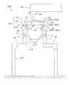
- FIG. 1 shows a schematic diagram of a combination weighing device 100 according to an embodiment of the present invention.
- the article is supplied from the article supply unit 90 to the dispersion unit 10, and the article is supplied from the dispersion unit 10 to the plurality of radiation units 20 arranged radially in the circumferential direction of the dispersion unit 10.
- a pool hopper 30 is provided corresponding to each radiation unit 20 on the downstream side in the transport direction of the radiation unit 20, and articles from the radiation unit 20 are temporarily stored.
- a weighing hopper 40 is arranged corresponding to each pool hopper 30 and receives articles discharged from the corresponding pool hopper 30.
- Each of the plurality of weighing hoppers 40 weighs the stored articles, and a combination calculation is performed based on the measured values. Then, a combination of articles whose combination calculation result is a value within a predetermined allowable range is selected, and the articles are discharged from the weighing hopper 40 related to the combination.
- the combination weighing device 100 is arranged above a packaging device (not shown). As shown in FIG. 1, the combination weighing device 100 is installed above a gantry 91 provided in the vicinity of the packaging device. Work passages 92 are provided on four sides of the combination weighing device 100 so that an operator can access the combination weighing device 100 during an abnormality or maintenance.
- the combination weighing device 100 mainly includes an article supply unit 90, a dispersion unit 10, a plurality of radiation units 20 (20a to 20n), and a plurality of pool hoppers 30 (30a to 30n). And a plurality of weighing hoppers 40 (40a to 40n), one collective chute 110, a camera 60, a touch panel 70, and a control device 80.
- the combination weighing device 100 includes 14 radiation units 20, pool hoppers 30, and weighing hoppers 40, respectively.
- the plurality of radiating portions 20 (20a to 20n), the plurality of pool hoppers 30 (30a to 30n), and the plurality of weighing hoppers 40 (40a to 40n) constitute heads HD (HDa to HDn), respectively.
- heads HDa to HDn are arranged in a ring shape in the circumferential direction of the dispersion part with the dispersion part 10 as the center in plan view.
- Identification numbers 1 to 14 are assigned to the heads HDa to HDn, respectively.
- the heads HD assigned identification numbers 1 to 14 are shown as heads HDa to HDn, respectively.
- the heads HDa to HDn are arranged such that the heads HDa to HDn having large identification numbers come clockwise.
- the heads HDa to HDn, the radiating portions 20 (20a to 20n), the pool hoppers 30 (30a to 30n), and the weighing hoppers 40 (40a to 40n), respectively, are the same as the heads HDa to HDn.
- Identification numbers (1 to 14) are assigned.
- the radiation units 20a to 20n, the pool hoppers 30a to 30n, and the weighing hoppers 40a to 40n belonging to the same heads HDa to HDn are associated with each other.
- the article is conveyed from the article supply unit 90 to the dispersion unit 10, and then the article is conveyed from the dispersion unit 10 to the radiation units 20a to 20n. Further, the articles are supplied from the radiating units 20a to 20n to the pool hoppers 30a to 30n associated with the radiating units 20a to 20n. The articles supplied to the pool hoppers 30a to 30n are then supplied to the weighing hoppers 40a to 40n associated with the pool hoppers 30a to 30n. Thereafter, the articles are discharged from the weighing hoppers 40a to 40n to the collecting chute 110. The articles discharged to the collecting chute 110 are then put into the packaging device.
- the dispersing unit 10 and the radiating units 20a to 20n will be described as an article conveying unit.
- the article supply unit 90 is a unit that supplies articles to the dispersion unit 10.
- the article supply unit 90 is disposed above the dispersion unit 10 as shown in FIG.
- the article supply unit 90 is driven by the article supply unit driving unit 90a (see FIG. 3).
- the article supply unit 90 changes the operation / stop state and the amount of articles to be conveyed based on a control command sent from the control device 80 described later.
- the dispersing unit 10 is a unit that receives an article conveyed from the article supply unit 90 and conveys the article to the radiating unit 20. Specifically, the dispersion unit 10 disperses the article conveyed from the article supply unit 90 by vibration and sends it to each of the radiation units 20a to 20n.
- the distribution unit 10 mainly includes a distribution table (mounting unit) 11.
- the distribution table 11 receives articles conveyed from the article supply unit 90, and a large number of articles are placed thereon.
- the distribution table 11 is a flat conical table member.
- the dispersion table 11 vibrates by driving the dispersion table driving electromagnet 12 (see FIG. 3).
- the dispersion unit 10 vibrates the dispersion table 11 to convey the article placed on the dispersion table 11 in the radial direction while dispersing the article in the circumferential direction.
- the dispersion table drive electromagnet 12 of the dispersion unit 10 is controlled based on a control command sent from a control device 80 described later. Further, the amount of articles supplied from the dispersion unit 10 to the radiation unit 20 is also controlled based on a control command sent from the control device 80.
- the dispersion table driving electromagnet 12 changes the strength (vibration strength) for vibrating the dispersion table 11 and the time (vibration time) for vibrating the dispersion table 11 based on the control command.
- the initial setting values of the vibration intensity and vibration time of the dispersion table 11 are stored in the storage unit 81 of the control device 80 described later. The vibration intensity and the vibration time can be changed using a touch panel 70 described later.
- the radiation unit 20 receives an article from the dispersion unit 10 and supplies the article to the pool hopper 30.
- the radiating unit 20 receives the article supplied by the dispersing unit 10 and supplies the article to the pool hopper 30 arranged further downstream.
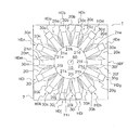
- Each of the radiation units 20a to 20n has radiation troughs (mounting units) 21a to 21n for receiving the articles conveyed by the dispersion unit 10. A large number of articles are placed on the radiation troughs 21a to 21n. As shown in FIG. 2, the radiation troughs 21a to 21n are arranged so as to extend radially around the dispersion unit 10. The radiating portions 20a to 20n are arranged on the outer edge side of the dispersing portion 10 so as to surround the dispersing portion 10. Each of the radiation troughs 21a to 21n is driven and vibrated by the radiation trough driving electromagnet 22 (see FIG. 3).
- the radiating unit 20 vibrates the radiating troughs 21a to 21n to convey the articles respectively placed on the radiating troughs 21a to 21n toward the outer edge. That is, each of the radiation units 20a to 20n conveys the article in a direction away from the dispersion unit 10.
- the articles conveyed by the radiating portions 20a to 20n are supplied to pool hoppers 30a to 30n disposed below the outer edges of the radiating portions 20a to 20n.
- the radiation trough drive electromagnets 22 of the radiation units 20a to 20n are controlled based on control commands sent from the control device 80 described later.
- the radiation trough drive electromagnet 22 controls each of the radiation parts 20a to 20n independently. Further, the amount of articles conveyed from each of the radiating units 20a to 20n to the pool hopper 30 is also controlled based on a control command sent from the control device 80.
- the radiation trough drive electromagnet 22 changes the vibration intensity and vibration time for vibrating the radiation troughs 21a to 21n based on the control command.
- the vibration time of 21a to 21n is one cycle time from when a radiation trough driving electromagnet 22 described later starts vibration of the radiation troughs 21a to 21n to when the vibration is stopped.
- the initial setting values of the vibration intensity and vibration time of the radiation troughs 21a to 21n are stored in the storage unit 81 of the control device 80 described later.
- the vibration intensity and vibration time can also be changed using the touch panel 70 described later.
- pool hopper 30 temporarily stores articles supplied from the radiating unit 20, and then discharges the stored articles to a weighing hopper 40 described later.
- the pool hopper 30 is disposed on the outer edge side of the radiating unit 20. Further, the pool hopper 30 is disposed below the radiating unit 20 so as to receive articles falling from the radiating unit 20.
- the pool hoppers 30a to 30n belonging to each of the heads HDa to HDn are disposed below the outer edges of the radiating portions 20a to 20n belonging to the same head HDa to HDn.
- the pool hopper 30 has openings at the upper and lower ends.
- the opening on the upper end side is an opening for receiving an article falling from the radiating portion 20.
- the opening on the lower end side is an opening for discharging articles in the pool hopper 30 to the weighing hopper 40.
- a gate 31 is attached to the opening on the lower end side. That is, the gate 31 constitutes the bottom of the pool hopper 30.
- the gate 31 is configured to be openable and closable.
- the gate 31 is driven by a pool hopper drive motor 32 (see FIG. 3).
- the pool hopper drive motor 32 is, for example, a stepping motor.
- the pool hopper drive motor 32 is driven by the control device 80.
- the control device 80 individually controls the gates 31 attached to the pool hoppers 30a to 30n.
- each gate 31 opens and closes independently.
- the gate 31 is opened, the articles stored in the pool hopper 30 are discharged to the weighing hopper 40.
- the weighing hopper 40 weighs the articles discharged by the pool hopper 30, and then discharges the weighed articles to the collecting chute 110.
- the weighing hopper 40 is disposed below the pool hopper 30 so as to receive articles dropped from the pool hopper 30.
- the weighing hoppers 40a to 40n belonging to the heads HDa to HDn are arranged below the pool hoppers 30a to 30n belonging to the same heads HDa to HDn.
- the weighing hopper 40 also has openings at the upper and lower ends.
- the opening on the upper end side is an opening for receiving articles falling from the pool hopper 30.
- the opening on the lower end side is an opening for sending articles in the weighing hopper 40 to the collecting chute 110.
- a gate 41 is attached to the opening on the lower end side. That is, the gate 41 constitutes the bottom of the weighing hopper 40.
- the gate 41 is configured to be openable and closable.
- the gate 41 is driven by a weighing hopper drive motor 42 (see FIG. 3).
- the weighing hopper drive motor 42 is, for example, a stepping motor.
- the weighing hopper drive motor 42 is driven by the control device 80.
- the control device 80 individually controls the gates 41 attached to the weighing hoppers 40a to 40n. That is, each gate 41 performs an opening / closing operation independently. When the gate 41 is opened, the articles stored in the weighing hopper 40 fall on the collecting chute 110.
- Each weighing hopper 40a to 40n has a load cell 43, respectively.
- the articles held by the weighing hoppers 40a to 40n are weighed by the load cell 43.
- the weighing result of the article by the load cell 43 is sent to the control device 80 described later as a weighing value as needed.
- the collecting chute 110 collects articles discharged from the weighing hopper 40 and discharges them outside the combination weighing device 100. The discharged articles are discharged to a packaging machine or the like (not shown) disposed below the collecting chute 110.
- the camera 60 is an example of a detection unit.
- the camera 60 continuously captures images of the article conveyance unit (conveyance unit image).
- the camera 60 is a so-called TOF (Time Of Flight) camera, and includes an irradiation unit and an imaging unit (not shown).
- the TOF camera used in the present embodiment outputs a distance from the camera 60 for each transport area stored in a transport area position storage unit 81d to be described later corresponding to the surface imaged by itself. . That is, the camera 60 detects the state of the article in a non-contact manner for each conveyance area stored in a conveyance area position storage unit 81d described later. Specifically, the camera 60 detects the distance from the camera 60 to the imaging target in a non-contact manner for each transport area stored in a transport area position storage unit 81d described later, and outputs the detection result.
- TOF Time Of Flight
- the mounting unit means the dispersion table 11 of the dispersion unit 10 and the radiation trough 21 of the radiation unit 20 as described above.
- the conveyance unit image includes an image of the article on the dispersion table 11 and the radiation trough 21.
- the camera 60 is arranged at the center of the discharge part of the article supply unit 90 as shown in FIG. That is, the camera 60 images the placement unit from directly above the dispersion unit 10.
- the conveyance unit image is an image captured from directly above the dispersion unit 10.
- the camera 60 is disposed at the center position of the dispersion unit 10 in plan view. That is, the combination weighing device 100 according to the present embodiment is provided with one camera 60.
- the lens of the camera 60 faces the central direction of the dispersion unit 10. Note that the number of cameras 60 is an example, and a plurality of cameras 60 may be provided.
- the camera 60 captures an image for each weighing cycle to be described later, and outputs each distance from the camera 60 to each conveyance area set in a conveyance area position storage unit 81d to be described later for each weighing cycle. In other words, the camera 60 detects the state of the article on the placement unit for each conveyance area stored in a conveyance area position storage unit 81d described later for each weighing cycle.
- the touch panel 70 is a liquid crystal display (LCD).
- the touch panel 70 functions as an input unit and a display unit.
- the touch panel 70 receives various settings related to combination weighing.
- the touch panel 70 displays the operation status and setting information of the combination weighing device 100.
- the operation status includes the operation / stop status of the combination weighing device 100, the weight value of the articles weighed by the respective weighing hoppers 40a to 40n, the combination weighing result, and the like.
- the operating status of the combination weighing device 100 displayed on the touch panel 70 changes almost in real time.
- the operation status of the combination weighing device 100 includes a warning indicating a conveyance abnormality.
- the warning is displayed on the touch panel 70 when an article conveyance abnormality in the article conveyance unit is determined by the control device 80 described later.
- the setting information is information regarding initial settings and settings accepted by the touch panel 70.
- the settings accepted by the touch panel 70 include the vibration intensity and vibration time of the dispersion table 11 and the vibration intensity and vibration time of the radiation troughs 21a to 21n described above.
- the settings accepted by the touch panel 70 include weighing speed setting of the combination weighing device 100, setting of a plurality of conveyance areas in the article conveyance unit, timing adjustment, and the like.
- the weighing speed of the combination weighing device 100 is the number of combination weighings performed per unit time (1 minute). In the present embodiment, for example, since combination weighing (weighing cycle) is performed every 1 sec, the weighing speed is 60 times / minute.
- the setting of the article conveyance area in the article conveyance unit means that an area in which an article is conveyed by each of the radiation units 20a to 20n among a plurality of areas included in the conveyance unit image and an identification number of the radiation unit 20a to 20n. This is a setting for association.
- the setting of the article conveyance area in the article conveyance unit is associated with which part of the conveyance unit image corresponds to which part of the article conveyance unit (which part of the dispersion table 11 and the radiation troughs 21a to 21n). It is a setting for.
- the association is performed using the dispersion table 11 and the images of the radiation troughs 21a to 21n displayed on the touch panel 70.
- An image (setting image) used for setting the association is displayed so that a specific area can be specified on the touch panel 70.
- the region surrounded by the points is changed to a specific feeder ( It is set as an area (conveyance area) where the article is conveyed by the radiating unit 20).
- the transport area is further subdivided and set.
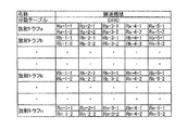
- association information between the distribution table 11 and each of the radiation units 20a to 20n and the setting image conveyance area is generated (see FIG. 7).
- Timing adjustment which is one of the settings accepted by the touch panel 70, is adjustment of timing related to timing for opening and closing the gate 31 of the pool hopper 30 and the gate 41 of the weighing hopper 40.
- the setting accepted by the touch panel 70 is stored in the storage unit 81 of the control device 80 described later.
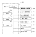
- the control device 80 is a device for controlling the combination weighing device 100. As shown in FIG. 3, the control device 80 includes an article supply unit drive unit 90a, a dispersion table drive electromagnet 12, a radiation trough drive electromagnet 22, a pool hopper drive motor 32, a weighing hopper drive motor 42, a load cell 43, a camera 60, and a touch panel. 70 or the like.
- the control device 80 includes a CPU 80a, a ROM 80b, a RAM 80c, and an HDD 80d.
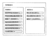
- the control device 80 functions as a storage unit 81 and a calculation unit 82.
- storage part 81 and the calculating part 82 are demonstrated using FIG.
- the storage unit 81 includes a ROM 80b, a RAM 80c, and an HDD 80d.
- the storage unit 81 stores a program to be read and executed by the CPU, various settings received by the touch panel 70, various data necessary for arithmetic processing, operation data, results obtained by arithmetic processing, and the like. .
- the storage unit 81 mainly includes a transfer region height storage unit 81a, a transfer region placement amount storage unit 81b, a drive data storage unit 81c, a transfer region position storage unit 81d, a transfer region distance storage unit 81e, and a transfer A region area storage unit 81f and a reservation storage unit 81g are included.
- Transport area height storage unit 81a captures articles for each transport area (described later) of the article transport unit captured by the camera 60 and calculated by the article height calculation unit 82a (described later). The height is remembered.
- the conveyance area height storage unit 81a stores the height of the article for each conveyance area in association with the time for each weighing cycle. In the present embodiment, data for the past one hour is stored in the transport area height storage unit 81a.
- the article placement weight for each transport region (described later) of the article transport unit calculated by the article placement weight calculation unit 82b (described later) is stored. It is remembered.
- the loading amount for each transfer region is stored in the transfer region placement amount storage unit 81b in association with the time for each weighing cycle.
- data for the past hour is stored in the transport area placement amount storage unit 81b.
- the drive data storage unit 81c stores drive data of each component included in the combination weighing device 100.
- the drive data includes the driving state of the article supply unit 90 (whether articles are being supplied), the open / closed state (ON / OFF) of the gate 31 of the pool hopper 30 and the gate 41 of the weighing hopper 40, and the like. .
- the drive data includes drive data for the dispersion unit 10 and the radiation units 20a to 20n.
- the drive data of the dispersion unit 10 and the radiation units 20a to 20n is data relating to the vibration intensity and vibration time of the dispersion unit 10 and the radiation units 20a to 20n.
- vibration intensity is a number from 0 to 99 and vibration time is stored in units of msec.
- the information stored in the drive data storage unit 81c is stored in association with the time when the drive data is obtained.
- data for the past hour is stored in the drive data storage unit 81c.
- Transport region position storage unit 81d indicates which part of the imaging region corresponds to which transport region of the article transport unit (the dispersion unit 10 and each of the radiation units 20a to 20n). The data shown is stored.
- a setting image is displayed on the touch panel 70, and the position of the entire area of the radiation trough 21k is specified by touching the touch panel at the position of the black dot shown in FIG.
- the conveyance area is set by dividing into 10 areas Rk-1-1 to Rk-5-2 shown in FIG.
- the transport area of the radiation trough 21k is the left area downstream of Rk-1-1, the right area of Rk-1-2 in the article conveyance direction, and the left area upstream of the next article conveyance direction.
- Rk-2-1 and Rk-2-1 on the right area are divided into a total of 10 areas, 5 divisions in the conveyance direction of the article and 2 divisions in the width direction in the conveyance direction.
- the touch panel 70 is operated to call the Rk-1-1 portion of the transport area position storage unit 81d shown in FIG. 7, and a range corresponding to that area is designated on the touch panel 70 in the setting image shown in FIG. To do.
- the coordinate value of the region of Rk-1-1 is set in the storage unit related to Rk-1-1 of the transport region position storage unit 81d.
- Rk-1-2 to Rk-5-2 are similarly set, and the setting of all the transport areas of the radiation trough 21k is completed.
- the transport area distance storage unit 81e stores the distance from the camera 60 to the center of each transport region set by the transport region position storage unit 81d. In the transfer area distance storage unit 81e, the distance to the center of each transfer area measured by the camera 60 in a state where there are no articles in the dispersion unit 10 and the radiating unit 20 is stored for each transfer area.
- Transport region area storage unit 81f stores the area of each transport region calculated from the coordinates of the transport region stored in the transport region position storage unit 81d for each transport region. Yes.
- the reservation storage unit 81g includes a reservation number of an item to be weighed, a measurement value, a measurement speed, a target supply weight of the head, vibration intensity and vibration time of the dispersion unit 10, and vibration intensity and vibration of the radiation unit 20.
- the density data of the article to be weighed is stored with time and the like.
- vibration intensity and vibration time of the radiating unit 20 as initial values are set so that the article advances a distance corresponding to one region in the conveyance direction set in the conveyance region position storage unit 81d by driving the radiating unit once. Is set to such intensity and time.
- the strength and strength are set such that all articles placed on one radiating unit 20 are supplied to the pool hopper 30 in five weighing cycles. Time and default settings.
- the calculation unit 82 is mainly composed of the CPU 80a.
- the CPU 80a controls the operation of the combination weighing device 100 by reading and executing a control program stored in the ROM 80b and the HDD 80d in cooperation with the RAM 80c.
- the calculation unit 82 includes an article height calculation unit 82a, an article placement weight calculation unit 82b, and a drive data generation unit 82c.
- the article height calculation unit 82a is an example of a height calculation unit.
- the article height calculation unit 82a calculates the height of the article on the placement unit for each conveyance area.
- the article height calculation unit 82a outputs the distance L1 from the camera 60 to the center of each conveyance area in the state where the article is placed, which is output for each weighing cycle. Received as a detection result.
- the distance L0 from the camera 60 to each conveyance area when there is no article is stored for each conveyance area in the conveyance area distance storage unit 81e. Therefore, the article height L of each conveyance area is calculated by subtracting L1 from L0 of the corresponding conveyance area.
- the article height calculation unit 82a is based on the distance L1 to the center of each conveyance area in the state where the article is placed, which is the detection result of the camera 60. Calculate the height.
- the article placement weight calculation unit 82b is an example of a placement amount calculation unit.
- the article placement weight calculation unit 82b multiplies the article height L for each conveyance region calculated by the article height calculation unit 82a by the area of the corresponding conveyance region stored in the conveyance region area storage unit 81f. Furthermore, the article placement weight for each transport area is calculated by multiplying the density of the articles stored in the reservation storage unit 81g. In other words, the article placement weight calculation unit 82b detects the article for each transport area based on the distance L1 to the center of each transport area in the state where the article is placed, which is the detection result of the camera 60. Calculate the loading weight.
- the drive data generation unit 82c is an example of a supply control unit.
- the drive data generation unit 82c generates a control command for controlling each unit (the dispersion unit 10, the radiation unit 20, the pool hopper 30, the weighing hopper 40, etc.) connected to the control device 80.
- the control command is sent to each unit through a communication unit (not shown) and executed.
- the generation of drive data for the radiation unit 20 by the drive data generation unit 82c will be described taking generation of drive data for the radiation unit 20k as an example.
- the drive data generation unit 82c sets the article placement weight in the transport region at the most downstream side of the radiation trough 21k recorded in the transport region placement amount storage unit 81b (if the radiation trough 21k, the transport region Rk-1-1). Based on the total weight of the article placement weight with the transport region Rk-1-2), the vibration intensity of the radiation unit 20k corresponding to the supply weight to be supplied to the pool hopper next time is calculated.
- the article placement weight of the transport area (hereinafter referred to as the next area) on the most downstream side of the radiation unit 20k is stored and known in the transport area placement amount storage unit 81b, this value is the reservation storage unit 81g. Is compared with the target supply weight of the head stored in If the article placement weight in the next area of the radiation unit 20k is within a predetermined range with respect to the target supply weight of the head stored in the reservation storage unit 81g, the drive data generation unit 82c does not change the vibration intensity.
- the drive data generation unit 82c calculates the insufficient weight and vibrates so that the supply weight of the article to be supplied next time becomes the supply target weight. Increase strength.
- the relationship between the vibration intensity and the transport distance is proportional in the predetermined vibration region, and is one upstream from the most downstream side of the radiating unit 20k (referred to as the “second-pass region”, in the radiation trough 21k, the transport region Rk-2-1 and the transport region). Since the article placement weight in the transport area Rk-2-2) is also known, the vibration intensity to be changed is calculated so as to correspond to the shortage by using the articles in the successive areas.
- the article placement weight of the next area is 30 g
- the article placement weight of the next area is 20 g
- the supply target weight is 40 g
- the shortage weight is calculated as 10 g.
- the vibration intensity before the change is 50, for example.
- the vibration intensity may be set to 75.
- the drive data generation unit 82c reduces the vibration intensity.
- the vibration intensity is calculated in the same manner as when the vibration intensity is increased when the vibration intensity is decreased.
- the drive data generation unit 82c generates the vibration intensity of the dispersion unit 10 and each radiation unit 20 based on the article placement weight for each conveyance region stored in the conveyance region placement amount storage unit 81b. To do. In other words, the drive data generation unit 82c generates the vibration intensity of each radiating unit 20 based on the article height for each conveyance region used for calculating the article placement weight for each conveyance region. Furthermore, in other words, the drive data generation unit 82c is used to calculate the height of the article for each conveyance area, and is output from the camera 60, and the state of the article on the placement unit for each conveyance area (the article is loaded). Based on the distance L1) to the center of each transport area in the placed state, the vibration intensity of each radiation unit 20 is generated.
- the drive data generation unit 82c repeats such an operation every measurement cycle.
- the combination weighing device 100 calculates drive data by the drive data generation unit 82c based on the article placement weight of each conveyance area while calculating the article placement weight of each conveyance area for each weighing cycle. To continue the combination weighing operation.
- the transport region can be further subdivided with respect to the slit light irradiation direction in the transport direction as compared with the TOF method.
- the TOF camera is used as the detection unit, but instead, the side wall of the radiation trough is inclined to form an article transport path in an inverted trapezoidal shape or an inverted V shape, You may image with a camera from upper direction, and may detect the length and area of the part which is not hidden with the article
- the height of the article can be calculated. This makes it possible to subdivide the region division in the transport direction. By subdividing the region division, the calculation of the article placement weight is subdivided, so that accurate supply control is possible.
- the article placement weight for each area of the article on the placement unit is used for the combination weighing, but may be used for determining whether or not the additional supply is appropriate. As a result, it is possible to prevent a reduction in operating rate and a reduction in measurement accuracy that would cause the head to become inoperable due to an overcapacity due to inadvertent additional supply.
- the vibration device is used for the dispersion unit 10 and the radiation unit 20, but a belt method or a screw method may be used. Depending on the article or the like, even an article that cannot be conveyed by absorbing vibration can be conveyed.
- the correlation between the vibration strength and the vibration time of the article may be measured using the article placement weight for each article region on the placement unit. This makes it possible to accurately calculate the initial value, the vibration intensity at the time of operation, and the vibration time, thereby increasing the accuracy of supply control for all articles.
- the radiating unit 20 is disposed so as to surround the dispersion unit 10, and the weighing hopper 40 is disposed below the radiating unit 20 (FIGS. 1 and FIG. 1). 2).
- the same configuration as the combination weighing device according to the first embodiment can be applied to a so-called linearly arranged combination weighing device instead.
- the drive data generation unit 82c causes the article placement weight calculation unit 82b on the radiation trough 21 for each region along the conveyance direction calculated by the article height calculation unit 82a.
- Drive control of the article conveyance unit based on the article placement weight for each region along the conveyance direction calculated based on the height of the article (determination of the vibration intensity of each radiation unit 20 in the first embodiment) I do.
- the drive data generation unit 82c calculates the article height (article placement weight) on the radiation trough 21 for each region along the transport direction calculated by the article height calculation unit 82a.
- the driving control of the radiating unit 20 may be performed on the basis of the value corresponding to (1). More specifically, the drive data generation unit 82c replaces the article placement weight for each area along the conveyance direction, stored in association with the time in the conveyance area placement amount storage unit 81b, and the conveyance area height. You may perform drive control of the radiation
- the drive data generation unit 82c detects the distance to the center of each conveyance area of the placement unit in a state where the article is placed, which is detected by the camera 60 instead of the height of the article. You may perform drive control of the radiation
- the radiating unit 20 is based on the distance L1 to the center of each transport area of the placement section, the height of the article for each transport area of the placement section, and the like when the article is placed.
- the value may not be a value expressed in a unit system (for example, an international unit system).
- a value determined based on a reference different from a normal unit system may be used as the distance L1.
- the amount represented as 50 cm in the international unit system is represented as 100.
- a small value may be used as the distance L1.
- the camera 60 is a region along the transport direction and the transport direction of the radiating unit 20 (more specifically, the direction orthogonal to the cross direction) (the width direction of the radiation trough 21).
- a physical quantity distance from the camera 60 to the center of each region
- the camera 60 may detect a physical quantity for grasping the height of the article on the placement unit only for each region along the conveyance direction of the radiating unit 20.
- the article height calculation unit 82a may calculate the height of the article on the radiation trough 21 for each region along the conveyance direction based on the detection result.
- the article placement weight calculation unit 82b may calculate the article placement weight on the radiation trough 21 for each region along the conveyance direction.
- the camera 60 emits radiation for each of a plurality of areas along the direction (the width direction of the radiation trough 21) intersecting the conveyance direction of the radiation unit 20. It is preferable to detect the state of the article on the trough 21. Moreover, it is preferable that the article height calculation unit 82a calculates the height of the article on the radiation trough 21 for each region along the direction intersecting the transport direction based on the detection result. Moreover, it is preferable that the article placement weight calculation unit 82b calculates the article placement weight on the radiation trough 21 for each region along the direction intersecting the transport direction.
- the detection unit may be an optical displacement sensor.
- the optical displacement sensor has a light source and a light receiving element (PSD (Position Sensitive Device), CCD (Charge Coupled Device), etc.), and the light emitted from the light source is reflected on the article and forms an image on the light receiving element. By capturing the change in position, the distance to the article can be detected as the state of the article.
- PSD Position Sensitive Device
- CCD Charge Coupled Device
- the detection unit may be an ultrasonic displacement sensor.
- the ultrasonic displacement sensor has a sensor head that transmits ultrasonic waves and receives ultrasonic waves reflected from the article, and measures the time difference between the transmission and reception of ultrasonic waves to determine the distance to the article. It can be detected as the state of the article.
- the article placement weight calculation unit 82b is configured for each region based on the article height for each region along the conveyance direction calculated by the article height calculation unit 82a.
- the article loading weight is calculated, the present invention is not limited to this.
- the article placement weight calculation unit 82b directly uses the distance L1 to the center of each conveyance area of the placement unit in a state where the article is placed, which is detected by the camera 60, and uses the article placement weight calculation unit 82b.
- the installed weight may be calculated.
- the camera 60 detects the state of the article on the placement unit in a non-contact manner, and the article on the placement unit based on the detection result.
- the drive data generation unit 82c performs drive control of the article transport unit based on the physical quantity related to the height of the item.
- the combination weighing device may be configured as follows.
- the camera 60 has, as the state of the article on the placement unit, for example, an article in each conveyance region that is an amount correlated with the article placement weight on the placement unit.
- the area of the area to be detected is detected without contact.
- the calculation unit of the control device 80 calculates the ratio of the area of the portion where the article is present to the total area for each conveyance region.
- the calculation unit of the control device 80 calculates the ratio of the area of the portion where the article is present to the total area for each region along the transport direction.
- the drive data generation unit 82c performs the supply control of the article by performing the drive control of the article conveyance unit based on the ratio of the area of the part where the article exists to the total area for each region along the conveyance direction.
- the supply control of the articles in the article transport unit can be performed with high accuracy, and operation with improved weighing accuracy of the combination weighing device and operation without reducing the operating rate of the combination weighing device are possible. It becomes.
- Dispersing part (article conveying part) 11 Dispersion table (mounting section) 20 (20a to 20n) Radiation section (article transport section) 21 (21a-21n) Radiation trough (mounting part) 30 (30a-30n) Pool hopper 31 Gate 32 Pool hopper drive motor 40 (40a-40n) Weigh hopper 41 Gate 42 Weigh hopper drive motor 43 Load cell 60 Camera 70 Touch panel (display unit) 80 control device 81 storage unit 81a transport region height storage unit 81b transport region placement amount storage unit 81c drive data storage unit 81d transport region position storage unit 81e transport region distance storage unit 81f transport region area storage unit 82 calculation unit 82a article height Height calculator (height calculator) 82b Article placement amount calculation unit (placement amount calculation unit) 82c Drive data generation unit (supply control unit) 90 Article supply unit (supply unit) 100 combination weighing device
Landscapes
- Physics & Mathematics (AREA)
- General Physics & Mathematics (AREA)
- Feeding Of Articles To Conveyors (AREA)
- Filling Or Emptying Of Bunkers, Hoppers, And Tanks (AREA)
- Control Of Conveyors (AREA)
Abstract
Description
以下、図面を参照しつつ、本発明の一実施形態に係る組合せ計量装置100について説明する。
まず、図1に、本発明の一実施形態に係る組合せ計量装置100の概略図を示す。組合せ計量装置100では、物品供給ユニット90から物品が分散部10に供給され、分散部10の周方向に放射状に配置された複数の放射部20に分散部10から物品が供給される。また、組合せ計量装置100では、放射部20の搬送方向下流に放射部20ごとに対応してプールホッパ30が備えられ、放射部20からの物品が一時貯留される。
(2-1)物品供給ユニット
物品供給ユニット90は、分散部10に物品を供給するユニットである。物品供給ユニット90は、図1に示すように、分散部10の上方に配置されている。物品供給ユニット90は、物品供給ユニット駆動部90aによって駆動される(図3参照)。
分散部10は、上述した物品供給ユニット90から搬送された物品を受けて、当該物品を放射部20へ搬送するユニットである。具体的に、分散部10は、物品供給ユニット90から搬送された物品を振動により分散させて各放射部20a~20nに送る。
放射部20は、分散部10から物品を受け取り、当該物品をプールホッパ30に供給する。放射部20は、分散部10によって供給された物品を受け取り、さらに下流に配置されたプールホッパ30へ物品を供給する。
プールホッパ30は、放射部20から供給される物品を一時的に貯留し、その後、貯留した物品を後述する計量ホッパ40に排出する。プールホッパ30は、放射部20の外縁側に配置される。また、プールホッパ30は、放射部20から落下する物品を受けるように、放射部20の下方に配置される。具体的に、各ヘッドHDa~HDnに属するプールホッパ30a~30nは、同一ヘッドHDa~HDnに属する放射部20a~20nの外縁側下方に配置される。
計量ホッパ40は、プールホッパ30によって排出される物品を計量し、その後、計量した物品を集合シュート110に排出する。計量ホッパ40は、プールホッパ30から落下した物品を受けるように、プールホッパ30の下方に配置される。具体的に、各ヘッドHDa~HDnに属する計量ホッパ40a~40nは、同一ヘッドHDa~HDnに属するプールホッパ30a~30nの下方に配置される。
集合シュート110は、計量ホッパ40から排出される物品を集合させて組合せ計量装置100の外に排出する。排出された物品は、集合シュート110の下方に配置される図示しない包装機等に排出される。
カメラ60は、検知部の一例である。カメラ60は、物品搬送部の画像(搬送部画像)を連続的に撮像する。カメラ60は、いわゆるTOF(Time Of Flight)方式のカメラで、図示しない照射部と撮像部とで構成されている。また、本実施例で用いるTOF方式のカメラは、それ自体で撮像した面に対応して、後述する搬送領域位置記憶部81dに記憶された各搬送領域ごとに、カメラ60からの距離を出力する。つまり、カメラ60は、後述する搬送領域位置記憶部81dに記憶された搬送領域ごとに、物品の状態を非接触で検知する。具体的には、カメラ60は、後述する搬送領域位置記憶部81dに記憶された搬送領域ごとに、カメラ60から撮像対象までの距離を、非接触で検知し、検知結果を出力する。
タッチパネル70は、液晶ディスプレイ(LCD)である。タッチパネル70は、入力部および表示部として機能する。タッチパネル70は、組合せ計量に関する各種設定を受け付ける。また、タッチパネル70は、組合せ計量装置100の運転状況や設定情報を表示する。運転状況には、組合せ計量装置100の運転/停止の状況、各計量ホッパ40a~40nによって計量される物品の重量値、組合せ計量結果等が含まれる。タッチパネル70に表示される組合せ計量装置100の運転状況は、ほぼリアルタイムで変化する。また、組合せ計量装置100の運転状況には、搬送異常を示す警告が含まれる。警告は、後述する制御装置80によって物品搬送部における物品の搬送異常が判定された場合に、タッチパネル70に表示される。設定情報は、初期設定およびタッチパネル70で受け付けられた設定に関する情報である。
制御装置80は、組合せ計量装置100を制御するための装置である。制御装置80は図3に示すように、物品供給ユニット駆動部90a、分散テーブル駆動電磁石12、放射トラフ駆動電磁石22、プールホッパ駆動モータ32、計量ホッパ駆動モータ42、ロードセル43、カメラ60、およびタッチパネル70等に接続されている。
記憶部81は、ROM80b、RAM80cおよびHDD80dによって構成されている。記憶部81は、CPUが読み出して実行するためのプログラムや、タッチパネル70で受け付けた各種設定、演算処理のために必要な各種データ、運転データや演算処理によって得られた結果等が記憶されている。
搬送領域高さ記憶部81aには、カメラ60によって撮像され、後述する物品高さ算出部82aにて算出された物品搬送部の後述する各搬送領域ごとの物品高さが記憶されている。
搬送領域載置量記憶部81bには、後述の物品載置重量算出部82bで算出された物品搬送部の後述する各搬送領域ごとの物品載置重量が記憶されている。
駆動データ記憶部81cには、組合せ計量装置100に含まれる各構成の駆動データが記憶されている。例えば、駆動データには、物品供給ユニット90の駆動状態(物品を供給しているか否か)、プールホッパ30のゲート31および計量ホッパ40のゲート41の開閉状態(ON/OFF)等が含まれる。
搬送領域位置記憶部81dには、撮像領域のどの部分が、物品搬送部(分散部10および各放射部20a~20n)のうち、どの搬送領域に対応するかを示すデータが記憶されている。
搬送領域距離記憶部81eには、カメラ60から搬送領域位置記憶部81dで設定された各搬送領域の中心までの距離が記憶される。搬送領域距離記憶部81eには、分散部10および放射部20に物品が無い状態でカメラ60にて測定された各搬送領域の中心までの距離が、各搬送領域ごとに記憶される。
搬送領域面積記憶部81fには、搬送領域位置記憶部81dに記憶された搬送領域の座標から算出された各搬送領域の面積が、各搬送領域ごとに記憶されている。
予約記憶部81gには、計量する物品の予約番号、計量値、計量スピード、ヘッドの供給目標重量、分散部10の振動強度や振動時間、放射部20の振動強度や振動時間等と共に、計量する物品の密度データが記憶されている。
演算部82は、主として、CPU80aから構成されている。CPU80aは、RAM80cと協働しつつ、ROM80bおよびHDD80dに記憶されている制御プログラムを読み出して実行することにより、組合せ計量装置100の動作を制御する。演算部82は、物品高さ算出部82aと、物品載置重量算出部82bと、駆動データ生成部82cと、を有する。
物品高さ算出部82aは、高さ算出部の一例である。物品高さ算出部82aは、各搬送領域ごとの戴置部上の物品の高さを算出する。
物品載置重量算出部82bは、載置量算出部の一例である。物品載置重量算出部82bは、物品高さ算出部82aによって算出された各搬送領域ごとの物品高さLに、搬送領域面積記憶部81fに記憶された、対応する搬送領域の面積を掛け、さらに、予約記憶部81gに記憶された物品の密度を掛けることで、各搬送領域ごとの物品載置重量を算出する。言い換えれば、物品載置重量算出部82bは、カメラ60の検知結果である、物品が載置された状態での各搬送領域ごとのその領域中心までの距離L1に基づき、各搬送領域ごとの物品載置重量を算出する。
駆動データ生成部82cは、供給制御部の一例である。駆動データ生成部82cは、制御装置80に接続された各部(分散部10、放射部20、プールホッパ30、計量ホッパ40等)を制御するための制御指令を生成する。制御指令は、図示しない通信部を介して各部に送られて実行される。
以下に、上記第1実施形態の変形例を示す。なお、変形例は、互いに矛盾しない範囲で、複数組み合わされてもよい。
上記第1実施形態に係る組合せ計量装置100では、各放射トラフの搬送領域が10分割されたが、さらに細分化されてもよい。細分化されることで、物品載置重量の算出が細分化されるため、正確な供給制御が可能となる。
上記第1実施形態に係る組合せ計量装置100では、検知部にTOFカメラを用いたが、それに代えて、光切断法で物品高さが、物品の状態として検出されてもよい。
上記第1実施形態に係る組合せ計量装置100では、検知部にTOFカメラを用いたが、それに代えて、放射トラフの側壁を傾斜させて物品の搬送経路を逆台形や逆V形に形成し、上方よりカメラで撮像し、側壁部の物品で隠れていない部分の長さや面積を、放射トラフ上の物品の状態として検知してもよい。
上記第1実施形態に係る組合せ計量装置100では、検知部にTOFカメラを用いたが、それに代えて、パターン照射法を用いてもよい。
上記第1実施形態に係る組合せ計量装置100では、載置部上の物品の領域ごとの物品戴置重量が、組合せ計量に用いられたが、追加供給の適否の判断に用いられてもよい。このことで不用意な追加供給による容量オーバーでヘッドが動作不能になるような稼働率低下や計量精度低下を防止できる。
上記第1実施形態に係る組合せ計量装置100では、駆動データ生成部82cが、放射部20の振動強度を制御する場合について説明したが、物品の性状や状況によっては放射部20の振動時間を制御対象としてもよく、または、両方を制御対象としてもよい。そうすることでさらに正確な供給制御が可能となる。
上記第1実施形態に係る組合せ計量装置100では、分散部10や放射部20に振動装置を用いたが、ベルト方式、スクリュー方式でもよい。物品等によっては振動を吸収して搬送できない物品でも搬送が可能となる。
上記第1実施形態に係る組合せ計量装置100では、放射部20の制御を説明したが、分散部10も同様に制御が行われてもよい。そうすることでさらに正確な供給制御が可能となる。
上記第1実施形態に係る組合せ計量装置100では、計量ホッパのみ組合せの対象にする組合せ計量に用いたが、各搬送領域ごとの物品載置重量値を組合せの対象にしてもよい。
上記第1実施形態に係る組合せ計量装置100では、載置部上の物品の領域ごとの物品戴置重量を用いて、振動強度や振動時間の物品に対する相関関係が測定されてもよい。このことで初期値や稼動時の振動強度や振動時間の算出する場合に正確に算出が可能となるため、あらゆる物品に対する供給制御の精度が上がる。
上記第1実施形態に係る組合せ計量装置100では、放射部20は、分散部10の回りを囲むように配置され、計量ホッパ40は放射部20の下方にそれぞれ配置されている(図1および図2参照)。
上記第1実施形態に係る組合せ計量装置100では、駆動データ生成部82cは、物品戴置重量算出部82bが、物品高さ算出部82aが算出する搬送方向に沿った領域ごとの放射トラフ21上の物品の高さに基づいて算出する、搬送方向に沿った領域ごとの物品戴置重量に基づいて、物品搬送部の駆動制御(上記第1実施形態では各放射部20の振動強度の決定)を行う。
上記第1実施形態に係る組合せ計量装置では、カメラ60は、放射部20の搬送方向および搬送方向に交差する(より具体的には直交する)方向(放射トラフ21の幅方向)に沿った領域ごとに、載置部上の物品の高さを把握するための物理量を(カメラ60から各領域の中心までの距離)を検知するが、これに限定されるものではない。例えば、カメラ60は、放射部20の搬送方向に沿った領域ごとにだけ、載置部上の物品の高さを把握するための物理量を検知してもよい。そして、物品高さ算出部82aは、その検知結果に基づいて、搬送方向に沿った領域ごとの放射トラフ21上の物品の高さを算出してもよい。また、物品戴置重量算出部82bは、搬送方向に沿った領域ごとの放射トラフ21上の物品戴置重量を算出してもよい。
上記第1実施形態に係る組合せ計量装置100では、検知部にTOFカメラが用いられるが、これに限定されるものではない。
上記第1実施形態に係る組合せ計量装置100では、物品戴置重量算出部82bは、物品高さ算出部82aが算出する搬送方向に沿った領域ごとの物品の高さに基づいて、領域ごとの物品戴置重量を算出しているが、これに限定されるものではない。例えば、物品戴置重量算出部82bは、カメラ60が検知する、物品が載置された状態での、戴置部の各搬送領域ごとのその領域中心までの距離L1を直接用いて、物品戴置重量を算出してもよい。
上記第1実施形態に係る組合せ計量装置100では、カメラ60が載置部上の物品の状態を非接触で検知し、この検知結果に基づいて載置部上の物品の高さに関する物理量に基づいて駆動データ生成部82cが物品搬送部の駆動制御を行うが、これに代えて、あるいは、これに加えて、組合せ計量装置は以下のように構成されてもよい。
11 分散テーブル(載置部)
20(20a~20n) 放射部(物品搬送部)
21(21a~21n) 放射トラフ(載置部)
30(30a~30n) プールホッパ
31 ゲート
32 プールホッパ駆動モータ
40(40a~40n) 計量ホッパ
41 ゲート
42 計量ホッパ駆動モータ
43 ロードセル
60 カメラ
70 タッチパネル(表示部)
80 制御装置
81 記憶部
81a 搬送領域高さ記憶部
81b 搬送領域載置量記憶部
81c 駆動データ記憶部
81d 搬送領域位置記憶部
81e 搬送領域距離記憶部
81f 搬送領域面積記憶部
82 演算部
82a 物品高さ算出部(高さ算出部)
82b 物品載置量算出部(載置量算出部)
82c 駆動データ生成部(供給制御部)
90 物品供給ユニット(供給ユニット)
100 組合せ計量装置
Claims (5)
- 物品の載置部と該載置部を駆動させる駆動部とを有し、該駆動部を駆動させることで前記物品を搬送方向下流に配置されたホッパに搬送させる物品搬送部と、
前記載置部上の前記物品の状態を非接触で検知する検知部と、
前記検知部の検知結果に基づき前記物品搬送部の駆動制御を行うことで前記物品の供給制御を行う供給制御部と、
を備える組合せ計量装置であって、
前記検知部は、前記搬送方向に沿った複数の領域について、前記領域ごとに前記物品の状態を検知し、
前記供給制御部は、前記領域ごとの前記物品の状態から把握される、前記領域ごとの前記載置部上の前記物品の高さに関する物理量に基づき前記駆動制御を行うことを特徴とする、
組合せ計量装置。 - 前記領域ごとの前記物理量を、時刻と関連させて記憶する記憶部をさらに有し、
前記供給制御部は、前記記憶部に記憶された、時刻と関連させた前記領域ごとの前記物理量に基づき前記駆動制御を行うことを特徴とする、
請求項1に記載の組合せ計量装置。 - 前記検知部の検知結果に基づき、前記領域ごとの前記物理量として、前記領域ごとの前記載置部上の前記物品の高さを算出する高さ算出部をさらに備えることを特徴とする、
請求項1又は2に記載の組合せ計量装置。 - 前記検知部の検知結果に基づき、前記領域ごとの前記物理量として、前記領域ごとの前記載置部上の前記物品の戴置量を算出する戴置量算出部をさらに備えることを特徴とする、
請求項1又は2に記載の組合せ計量装置。 - 前記検知部が、所定サイクルごとに前記物品の状態を検知することを特徴とする、
請求項1から請求項4のいずれか1項に記載の組合せ計量装置。
Priority Applications (7)
| Application Number | Priority Date | Filing Date | Title |
|---|---|---|---|
| CN201590000218.5U CN205808532U (zh) | 2014-01-30 | 2015-01-28 | 组合计量装置 |
| JP2015559973A JP6255039B2 (ja) | 2014-01-30 | 2015-01-28 | 組合せ計量装置 |
| BR112016017547-6A BR112016017547B1 (pt) | 2014-01-30 | 2015-01-28 | dispositivo de pesagem combinado |
| EP15743210.5A EP3101398B1 (en) | 2014-01-30 | 2015-01-28 | Combination weighing apparatus |
| US15/112,323 US10151622B2 (en) | 2014-01-30 | 2015-01-28 | Combination weighing device for weighing articles conveyed to a hopper |
| MX2016009447A MX359813B (es) | 2014-01-30 | 2015-01-28 | Dispositivo de pesaje combinado. |
| AU2016101407A AU2016101407A4 (en) | 2014-01-30 | 2016-08-04 | Combination weighing device |
Applications Claiming Priority (2)
| Application Number | Priority Date | Filing Date | Title |
|---|---|---|---|
| JP2014-015612 | 2014-01-30 | ||
| JP2014015612 | 2014-01-30 |
Related Child Applications (1)
| Application Number | Title | Priority Date | Filing Date |
|---|---|---|---|
| AU2016101407A Division AU2016101407A4 (en) | 2014-01-30 | 2016-08-04 | Combination weighing device |
Publications (1)
| Publication Number | Publication Date |
|---|---|
| WO2015115475A1 true WO2015115475A1 (ja) | 2015-08-06 |
Family
ID=53757048
Family Applications (1)
| Application Number | Title | Priority Date | Filing Date |
|---|---|---|---|
| PCT/JP2015/052343 Ceased WO2015115475A1 (ja) | 2014-01-30 | 2015-01-28 | 組合せ計量装置 |
Country Status (8)
| Country | Link |
|---|---|
| US (1) | US10151622B2 (ja) |
| EP (1) | EP3101398B1 (ja) |
| JP (1) | JP6255039B2 (ja) |
| CN (1) | CN205808532U (ja) |
| AU (1) | AU2016101407A4 (ja) |
| BR (1) | BR112016017547B1 (ja) |
| MX (1) | MX359813B (ja) |
| WO (1) | WO2015115475A1 (ja) |
Cited By (3)
| Publication number | Priority date | Publication date | Assignee | Title |
|---|---|---|---|---|
| JP2017146162A (ja) * | 2016-02-16 | 2017-08-24 | 株式会社イシダ | 組合せ計量装置用の制御装置、組合せ計量装置及び組合せ計量装置システム |
| JP2017167084A (ja) * | 2016-03-18 | 2017-09-21 | 株式会社イシダ | 組合せ計量装置用の制御装置、組合せ計量装置及び組合せ計量装置システム |
| WO2020261679A1 (ja) * | 2019-06-25 | 2020-12-30 | 株式会社イシダ | 組合せ計量装置 |
Families Citing this family (6)
| Publication number | Priority date | Publication date | Assignee | Title |
|---|---|---|---|---|
| JP3197141U (ja) * | 2015-02-09 | 2015-04-23 | 株式会社イシダ | 組合せ計量装置 |
| JP7233096B2 (ja) * | 2019-06-25 | 2023-03-06 | 株式会社イシダ | 計量装置及び組合せ計量装置 |
| JP7526454B2 (ja) * | 2019-12-06 | 2024-08-01 | 株式会社イシダ | 改善判断システム |
| EP3933354B1 (de) | 2020-06-30 | 2022-10-19 | Multipond Wägetechnik GmbH | Verbesserte überwachung von kombinationswaagen durch einen 3d-sensor |
| JP7587817B2 (ja) * | 2020-11-27 | 2024-11-21 | 株式会社イシダ | 物品処理装置及び下流側装置 |
| JP2023137505A (ja) * | 2022-03-18 | 2023-09-29 | 株式会社イシダ | 組合せ計量装置 |
Citations (6)
| Publication number | Priority date | Publication date | Assignee | Title |
|---|---|---|---|---|
| JPH0643012A (ja) * | 1992-07-27 | 1994-02-18 | Ishida Co Ltd | 組合せ計量装置の被計量物供給方法及び被計量物供給装置 |
| WO1995031702A1 (en) | 1994-05-13 | 1995-11-23 | Ishida Co., Ltd. | Combination weighing apparatus |
| JP2004107077A (ja) * | 2002-09-20 | 2004-04-08 | Anritsu Sanki System Co Ltd | 分散供給装置及びそれを用いた組合せ計量装置 |
| JP2005162394A (ja) * | 2003-12-02 | 2005-06-23 | Ishida Co Ltd | 分散供給装置及びそれを備えてなる組合せ計量装置 |
| WO2013137008A1 (ja) * | 2012-03-16 | 2013-09-19 | 株式会社イシダ | 組合せ計量装置 |
| JP2013250143A (ja) | 2012-05-31 | 2013-12-12 | Ishida Co Ltd | 組合せ計量装置 |
Family Cites Families (10)
| Publication number | Priority date | Publication date | Assignee | Title |
|---|---|---|---|---|
| JPS59102123A (ja) * | 1982-12-03 | 1984-06-13 | Ishida Scales Mfg Co Ltd | 自動計量装置 |
| EP0112664B1 (en) | 1982-12-03 | 1990-01-24 | Kabushiki Kaisha Ishida Koki Seisakusho | Automatic weighing apparatus and method |
| JPS6144328A (ja) * | 1984-08-08 | 1986-03-04 | Ishida Scales Mfg Co Ltd | 組合せ計量装置のホツパ開閉装置 |
| US4708215A (en) * | 1984-08-08 | 1987-11-24 | Ishida Scales Manufacturing Company, Ltd. | Automatic weighing system |
| JPS6156916A (ja) * | 1984-08-28 | 1986-03-22 | Ishida Scales Mfg Co Ltd | 複合駆動装置及び複合駆動装置を用いた組合せ計量装置の被計量物分散供給装置 |
| US4711345A (en) | 1984-08-28 | 1987-12-08 | Ishida Scales Mfg. Co., Ltd. | Composite-motion drive unit and combinatorial weighing apparatus employing the same |
| US5270495A (en) * | 1992-02-28 | 1993-12-14 | Package Machinery Company | Combination weighing machine with feed control |
| FR2936601B1 (fr) * | 2008-09-30 | 2011-02-11 | Arbor Sa | Procede de traitement d'objets en fonction de leurs poids individuels |
| JP5785123B2 (ja) * | 2012-03-16 | 2015-09-24 | 株式会社イシダ | 組合せ計量装置 |
| EP2887029B1 (de) * | 2013-12-20 | 2016-03-09 | Multipond Wägetechnik GmbH | Befüllungsvorrichtung und Verfahren zum Erfassen einer Befüllung |
-
2015
- 2015-01-28 EP EP15743210.5A patent/EP3101398B1/en active Active
- 2015-01-28 CN CN201590000218.5U patent/CN205808532U/zh not_active Expired - Lifetime
- 2015-01-28 BR BR112016017547-6A patent/BR112016017547B1/pt not_active IP Right Cessation
- 2015-01-28 MX MX2016009447A patent/MX359813B/es active IP Right Grant
- 2015-01-28 WO PCT/JP2015/052343 patent/WO2015115475A1/ja not_active Ceased
- 2015-01-28 JP JP2015559973A patent/JP6255039B2/ja active Active
- 2015-01-28 US US15/112,323 patent/US10151622B2/en active Active
-
2016
- 2016-08-04 AU AU2016101407A patent/AU2016101407A4/en not_active Expired
Patent Citations (6)
| Publication number | Priority date | Publication date | Assignee | Title |
|---|---|---|---|---|
| JPH0643012A (ja) * | 1992-07-27 | 1994-02-18 | Ishida Co Ltd | 組合せ計量装置の被計量物供給方法及び被計量物供給装置 |
| WO1995031702A1 (en) | 1994-05-13 | 1995-11-23 | Ishida Co., Ltd. | Combination weighing apparatus |
| JP2004107077A (ja) * | 2002-09-20 | 2004-04-08 | Anritsu Sanki System Co Ltd | 分散供給装置及びそれを用いた組合せ計量装置 |
| JP2005162394A (ja) * | 2003-12-02 | 2005-06-23 | Ishida Co Ltd | 分散供給装置及びそれを備えてなる組合せ計量装置 |
| WO2013137008A1 (ja) * | 2012-03-16 | 2013-09-19 | 株式会社イシダ | 組合せ計量装置 |
| JP2013250143A (ja) | 2012-05-31 | 2013-12-12 | Ishida Co Ltd | 組合せ計量装置 |
Non-Patent Citations (1)
| Title |
|---|
| See also references of EP3101398A4 |
Cited By (4)
| Publication number | Priority date | Publication date | Assignee | Title |
|---|---|---|---|---|
| JP2017146162A (ja) * | 2016-02-16 | 2017-08-24 | 株式会社イシダ | 組合せ計量装置用の制御装置、組合せ計量装置及び組合せ計量装置システム |
| JP2017167084A (ja) * | 2016-03-18 | 2017-09-21 | 株式会社イシダ | 組合せ計量装置用の制御装置、組合せ計量装置及び組合せ計量装置システム |
| WO2020261679A1 (ja) * | 2019-06-25 | 2020-12-30 | 株式会社イシダ | 組合せ計量装置 |
| JP2021004756A (ja) * | 2019-06-25 | 2021-01-14 | 株式会社イシダ | 組合せ計量装置 |
Also Published As
| Publication number | Publication date |
|---|---|
| US20160341596A1 (en) | 2016-11-24 |
| BR112016017547B1 (pt) | 2021-03-09 |
| EP3101398B1 (en) | 2020-10-14 |
| BR112016017547A2 (pt) | 2017-08-08 |
| MX2016009447A (es) | 2016-10-13 |
| MX359813B (es) | 2018-10-11 |
| US10151622B2 (en) | 2018-12-11 |
| CN205808532U (zh) | 2016-12-14 |
| EP3101398A1 (en) | 2016-12-07 |
| JP6255039B2 (ja) | 2017-12-27 |
| EP3101398A4 (en) | 2017-02-08 |
| JPWO2015115475A1 (ja) | 2017-03-23 |
| AU2016101407A4 (en) | 2016-09-01 |
Similar Documents
| Publication | Publication Date | Title |
|---|---|---|
| JP6255039B2 (ja) | 組合せ計量装置 | |
| CN104487811B (zh) | 组合计量装置 | |
| JP6255036B2 (ja) | 組合せ計量装置 | |
| WO2013137008A1 (ja) | 組合せ計量装置 | |
| US20110019881A1 (en) | Method of creating dictionary for soil detection of a sheet, sheet processing apparatus, and sheet processing method | |
| WO2016129635A1 (ja) | 搬送装置及び組合せ計量装置 | |
| CN108469435A (zh) | 人工智能大米质检机器人及质检方法 | |
| CN110546467B (zh) | 组合秤 | |
| JP6484052B2 (ja) | 組合せ計量装置 | |
| JP6686649B2 (ja) | 骨材識別方法、骨材識別装置および骨材搬送貯蔵装置 | |
| JP4245903B2 (ja) | 組合せ計量計数装置 | |
| JP5288947B2 (ja) | 組合せ秤 | |
| JP5289216B2 (ja) | 組合せ秤 | |
| CN106971421A (zh) | 三维物体数据处理方法、处理设备及3d打印设备 | |
| JP3392537B2 (ja) | 組合せ計量方法及び組合せ計量装置 | |
| JP5154380B2 (ja) | 半自動式組合せ秤 | |
| JP3164903B2 (ja) | 組合せ計量装置の被計量物供給方法及び被計量物供給装置 | |
| JP4128861B2 (ja) | 組合せ計量装置 | |
| JP2010164336A (ja) | 組合せ秤 | |
| JP2022007575A (ja) | サイドガイド部材摩耗管理システムおよびサイドガイド部材摩耗管理装置 | |
| JP2003233796A (ja) | 計数システム | |
| KR100584618B1 (ko) | 화상 형성 장치의 소모품 잔여량 검출 방법 및 장치 | |
| JPH0763600A (ja) | はかり取り装置 | |
| JPS6344109A (ja) | ワ−クロ−ル表面の粗度測定方法およびその測定装置 | |
| JPS62133322A (ja) | 組合せ計量装置 |
Legal Events
| Date | Code | Title | Description |
|---|---|---|---|
| 121 | Ep: the epo has been informed by wipo that ep was designated in this application |
Ref document number: 15743210 Country of ref document: EP Kind code of ref document: A1 |
|
| ENP | Entry into the national phase |
Ref document number: 2015559973 Country of ref document: JP Kind code of ref document: A |
|
| WWE | Wipo information: entry into national phase |
Ref document number: 15112323 Country of ref document: US |
|
| WWE | Wipo information: entry into national phase |
Ref document number: MX/A/2016/009447 Country of ref document: MX |
|
| NENP | Non-entry into the national phase |
Ref country code: DE |
|
| REG | Reference to national code |
Ref country code: BR Ref legal event code: B01A Ref document number: 112016017547 Country of ref document: BR |
|
| REEP | Request for entry into the european phase |
Ref document number: 2015743210 Country of ref document: EP |
|
| WWE | Wipo information: entry into national phase |
Ref document number: 2015743210 Country of ref document: EP |
|
| ENP | Entry into the national phase |
Ref document number: 112016017547 Country of ref document: BR Kind code of ref document: A2 Effective date: 20160728 |