WO2015118796A1 - アンテナ方向調整装置およびアンテナ方向調整方法 - Google Patents
アンテナ方向調整装置およびアンテナ方向調整方法 Download PDFInfo
- Publication number
- WO2015118796A1 WO2015118796A1 PCT/JP2015/000057 JP2015000057W WO2015118796A1 WO 2015118796 A1 WO2015118796 A1 WO 2015118796A1 JP 2015000057 W JP2015000057 W JP 2015000057W WO 2015118796 A1 WO2015118796 A1 WO 2015118796A1
- Authority
- WO
- WIPO (PCT)
- Prior art keywords
- antenna
- unit
- camera
- antenna unit
- angular position
- Prior art date
- Legal status (The legal status is an assumption and is not a legal conclusion. Google has not performed a legal analysis and makes no representation as to the accuracy of the status listed.)
- Ceased
Links
Images










Classifications
-
- H—ELECTRICITY
- H01—ELECTRIC ELEMENTS
- H01Q—ANTENNAS, i.e. RADIO AERIALS
- H01Q1/00—Details of, or arrangements associated with, antennas
- H01Q1/12—Supports; Mounting means
- H01Q1/125—Means for positioning
- H01Q1/1257—Means for positioning using the received signal strength
-
- H—ELECTRICITY
- H01—ELECTRIC ELEMENTS
- H01Q—ANTENNAS, i.e. RADIO AERIALS
- H01Q3/00—Arrangements for changing or varying the orientation or the shape of the directional pattern of the waves radiated from an antenna or antenna system
- H01Q3/005—Arrangements for changing or varying the orientation or the shape of the directional pattern of the waves radiated from an antenna or antenna system using remotely controlled antenna positioning or scanning
-
- H—ELECTRICITY
- H01—ELECTRIC ELEMENTS
- H01Q—ANTENNAS, i.e. RADIO AERIALS
- H01Q3/00—Arrangements for changing or varying the orientation or the shape of the directional pattern of the waves radiated from an antenna or antenna system
- H01Q3/02—Arrangements for changing or varying the orientation or the shape of the directional pattern of the waves radiated from an antenna or antenna system using mechanical movement of antenna or antenna system as a whole
-
- H—ELECTRICITY
- H04—ELECTRIC COMMUNICATION TECHNIQUE
- H04B—TRANSMISSION
- H04B17/00—Monitoring; Testing
- H04B17/10—Monitoring; Testing of transmitters
- H04B17/101—Monitoring; Testing of transmitters for measurement of specific parameters of the transmitter or components thereof
-
- H—ELECTRICITY
- H04—ELECTRIC COMMUNICATION TECHNIQUE
- H04B—TRANSMISSION
- H04B17/00—Monitoring; Testing
- H04B17/10—Monitoring; Testing of transmitters
- H04B17/101—Monitoring; Testing of transmitters for measurement of specific parameters of the transmitter or components thereof
- H04B17/102—Power radiated at antenna
-
- H—ELECTRICITY
- H04—ELECTRIC COMMUNICATION TECHNIQUE
- H04B—TRANSMISSION
- H04B17/00—Monitoring; Testing
- H04B17/10—Monitoring; Testing of transmitters
- H04B17/11—Monitoring; Testing of transmitters for calibration
- H04B17/12—Monitoring; Testing of transmitters for calibration of transmit antennas, e.g. of the amplitude or phase
-
- H—ELECTRICITY
- H04—ELECTRIC COMMUNICATION TECHNIQUE
- H04B—TRANSMISSION
- H04B17/00—Monitoring; Testing
- H04B17/20—Monitoring; Testing of receivers
- H04B17/27—Monitoring; Testing of receivers for locating or positioning the transmitter
Definitions
- the present invention relates to an antenna direction adjusting device and an antenna direction adjusting method for adjusting the direction of an antenna.
- Patent Document 1 discloses a method for searching for a radio wave emission source.
- the direction finding device includes a direction finding array antenna and a camera attached to the array antenna.
- the lens of the camera is aligned so that its optical axis is substantially perpendicular to the vertical plane of the array antenna.
- an object estimated as a radio wave emission source is photographed with a camera.
- the received signal received by the array antenna is visualized by a technique such as radio holography, and is output as a wave source image.
- a screen for displaying the camera image and the wave source image in an overlapping manner is provided to the operator. By viewing this screen, the operator can specify the object of the radio wave generation source.
- a camera aligned with the antenna is provided on the antenna, and the camera is used as an aiming device. Identify the radio wave source with the camera and adjust the antenna orientation so that the radio wave source is in the center of the screen. If the radio wave generation source is specified using the camera as described above or the camera is used as an aiming device, it is surely helpful in adjusting the antenna direction.
- Patent Documents 1, 2, and 3 are considered to have the following problems.
- the alignment error must be less than 1.0 °, but it is impossible to manually align the antenna receiving direction and the optical axis of the camera with such high precision at the antenna installation site. Therefore, an antenna manufacturer manufactures and sells an antenna device with an aligned camera attached. However, if a camera is attached to each antenna, the cost increases considerably.
- An object of the present invention is to provide an antenna direction adjusting device and an antenna direction adjusting method capable of adjusting the antenna direction with high accuracy while having a simple and inexpensive configuration.
- the antenna direction adjusting device of the present invention is An antenna direction adjusting device for adjusting the direction of the antenna unit of an antenna device having an antenna unit and a direction adjusting component for changing the direction of the antenna unit, A camera fixed relative to the antenna unit; An electric unit that can be attached to the orientation adjustment component and changes the direction of the antenna unit by applying a force of the motor to the orientation adjustment component.
- a motion controller that provides a drive signal to the electric unit to adjust the direction of the antenna unit, The motion controller is The angular position of the antenna unit is obtained based on the image captured by the camera and the reception intensity of the radio wave received by the antenna unit, and a driving signal is given to the motorized unit to adjust the angular position of the antenna unit. It is characterized by.
- the antenna direction adjustment method of the present invention An antenna direction adjustment method for adjusting the direction of the antenna unit of an antenna device having an antenna unit and a direction adjusting component that changes the direction of the antenna unit, Attaching the camera to the antenna device such that the position and orientation of the antenna device are not displaced relative to the antenna unit; Attaching an electric part to the orientation adjusting component; Obtaining an angular position of the antenna unit at which reception intensity is maximized based on an image captured by the camera and reception intensity of radio waves received by the antenna unit; Providing a driving signal to the electric part to adjust the angular position of the antenna part.
- the antenna device can be installed quickly and accurately.
- the figure which shows the external appearance of an antenna apparatus The figure which looked at the antenna apparatus from the top. The figure which looked at the antenna apparatus from the side. The figure which shows the state which attached the antenna direction adjustment apparatus to the antenna apparatus. The figure which shows the state which attached the antenna direction adjustment apparatus to the antenna apparatus. The figure which shows the structure of a nut runner. Functional block diagram of the motion controller.
- the figure which shows a mode that the antenna apparatus was looked down on from right above.
- FIG. 1 is a diagram illustrating the antenna device 100.
- the antenna device 100 itself may be known.
- a so-called parabolic antenna is illustrated, but the type of antenna is not particularly limited in applying this embodiment.
- a planar antenna may be used as the directional antenna.
- FIG. 1 shows a state in which the antenna device 100 is viewed from behind with the antenna device 100 installed on the support column 10.
- the antenna device 100 includes an antenna unit 110, a transmission / reception unit 120, and attachment means 130.
- the antenna unit 110 is a parabolic antenna.
- the transmission / reception unit 120 is an electric circuit unit that incorporates a reception circuit 121 and a transmission circuit 122 (see FIG. 7), and modulates and demodulates signals as necessary.
- the transmission / reception unit 120 includes a storage box 123 serving as a housing and electric circuit units (121, 122) stored in the storage box 123, and is connected to the back surface of the antenna unit 110.
- the attachment means 130 installs and fixes the antenna unit 110 and the transmission / reception unit 120.
- pillar 10 is made into an example.
- the attachment means 130 includes a clamp portion 140, an azimuth movable metal fitting 150, an azimuth adjustment bolt (orientation adjustment component) 160, an elevation angle direction movable metal fitting 170, and an elevation angle adjustment bolt (orientation adjustment component) 180. .
- the clamp part 140 includes a U-shaped metal fitting 141 and a receiving metal fitting 142.
- the U-shaped metal fitting 141 is U-shaped and has a shape for holding the support column 10, and the support character is sandwiched between the U-shaped metal fitting 141 and the receiving metal fitting 142 on the back side of the receiving metal fitting 142.
- the receiving metal fitting 142 has a hollow rectangular parallelepiped shape whose one surface is open like a bowl, and receives the azimuthally movable metal fitting 150 inside.
- the front side of the receiving metal fitting 142 is open, and the azimuthally movable metal fitting 150 is received inside.
- the azimuthally movable metal fitting 150 is pivotally supported in a state of being received by the receiving metal fitting 142.
- the axis of the rotation axis is the vertical direction, and the azimuth movable metal fitting 150 can be displaced in the azimuth direction (Azimuth direction) by the rotation axis.
- the axial direction of the rotating shaft will be described with the general installation state of the antenna device 100 in mind.
- the degree of freedom in which the antenna unit 110 can be moved is only required to have two axes that can rotate independently, and there is no need to be caught in the direction of gravity such as vertical or horizontal.
- FIG. 2 is a view from the II direction in FIG. That is, FIG. 2 is a view of the antenna device 100 as viewed from above.
- Two elongated holes 143 and 143 are provided on the side surface of the receiving metal fitting 142 with the rotation shaft in between, and screws 144 and 144 are inserted into the azimuthally movable metal fitting 150 through the elongated holes 143 and 143. ing.
- the movable state and the fixed state of the azimuth movable metal fitting 150 can be switched by adjusting the tightening degree of the screws 144 and 144.
- the azimuth adjusting bolt 160 is screwed from the back surface of the receiving metal fitting 142, and its tip is connected to the back surface of the azimuth direction movable metal fitting 150.
- the azimuth adjusting bolt 160 is rotated and advanced and retracted, the azimuth movable metal fitting 150 is pushed and pulled, whereby the azimuth movable metal fitting 150 is rotated about the rotation axis. That is, the azimuth of the azimuth movable metal fitting 150 is changed by rotating the azimuth adjusting bolt 160.
- the azimuth adjusting bolt 160 is an orientation adjusting component that changes the direction (azimuth) of the antenna portion by applying force.
- the elevation direction movable metal fitting 170 is attached to the front side of the azimuth direction movable metal fitting 150.
- the elevation-direction movable metal fitting 170 is attached to the azimuth-direction movable metal fitting 150 on the proximal end side 171, and the distal end side is connected to the back surface of the antenna unit 110.
- the base end side 171 of the elevation direction movable metal fitting 170 is pivotally supported by the azimuth direction movable metal fitting 150 so as to be rotatable.
- the rotation axis is a horizontal direction, and the elevation angle direction movable metal fitting 170 can be displaced in the elevation angle direction (elevation direction) by this rotation axis.
- Two elongated holes 172 and 172 are provided on the proximal end side 171 of the elevation-direction movable metal fitting 170 with the rotation shaft in between, and screws 173 and 173 are inserted through the long holes 172 and 172 so that the azimuth movable metal fitting is inserted. 150 is screwed. By adjusting the tightening degree of the screws 173 and 173, the movable state and the fixed state of the elevation-direction movable metal fitting 170 can be switched.
- an elevation angle adjusting bolt 180 provided so as to hang in a substantially vertical direction is provided at the base end 171 of the elevation direction movable metal fitting 170, and the elevation angle adjustment bolt 180 is screwed to the azimuth direction movable metal fitting 150.
- the elevation angle adjusting bolt 180 is an orientation adjustment component that changes the orientation (elevation angle) of the antenna portion by applying a force.
- the antenna device 100 having such a configuration can change and adjust the azimuth and the elevation angle of the antenna unit 110 independently. Since the antenna unit 110 is connected to the tip of the elevation-direction movable bracket 170, the elevation angle of the antenna unit 110 can be changed together with the elevation-direction movable bracket 170. At this time, the elevation angle adjusting bolt 180 may be rotated. Further, since the base end 171 of the elevation-direction movable metal fitting 170 is attached to the azimuth-direction movable metal fitting 150, the elevation angle-direction movable metal fitting 170 and the antenna unit 110 can change the direction together with the azimuth-direction movable metal fitting 150. At this time, the azimuth adjusting bolt 160 may be rotated.
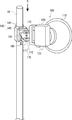
- FIG. 4 is a diagram illustrating a state where the antenna direction adjusting device 200 is attached to the antenna device 100.
- the antenna direction adjusting apparatus 200 includes a camera 210, two nut runners (electric parts) 220 and 230, a motion controller 400, and a personal computer (personal computer) 240.
- a state in which the antenna direction adjusting device 200 is attached to the antenna device 100 in this way is referred to as an antenna system.
- An operator who installs the antenna device 100 performs an operation of attaching the camera 210 and the nut runners 220 and 230 to the antenna device 100. After that, the direction of the antenna unit 110 is adjusted semi-automatically. This will be described below.
- the personal computer 240 is only convenient for using the input / output means (keyboard, display). If the input means and the output means are incorporated in the motion controller 400, the personal computer 240 is not necessary. .
- the input means includes a keyboard, a touch panel, various switches, various push buttons, and the like.
- the output means is typically a liquid crystal monitor.
- the camera 210 may be so-called digital, or may be a mobile terminal (for example, a mobile phone) having a function.
- the camera 210 is attached behind the antenna unit 110, and the direction in which the lens of the camera 210 captures an image has no relation to the reception direction of the antenna device 100.
- the direction in which the camera 210 captures an image is completely arbitrary.
- an object whose position is fixed (fixed) must be in the imaging region. That is, it is not useful in an imaging direction that only images the sky. Conversely, for example, it is preferable that a building such as a building or a house is reflected.
- An operator who installs the antenna device 100 looks around and determines the orientation of the camera 210 so that the above-described building is reflected as much as possible. Then, the camera 210 is fixedly attached to an appropriate position of the antenna device 100.
- the camera 210 When the camera 210 is installed on the upper surface of the storage box 123 as shown in FIG. 1, the camera 210 may be attached to the storage box 123 with double-sided tape if it is the simplest. However, no matter how simple the attachment is, the antenna unit 110 and the camera 210 must be such that their positions and orientations are not displaced relative to each other. In other words, if the position and orientation of the antenna unit 110 change, the position and orientation of the camera 210 must change in exactly the same way.
- FIG. 5 illustrates a state where the camera 210 is fixed to the antenna unit 110 using a predetermined mounting jig 211 for reference.
- the camera 210 may face in the same direction as the reception direction of the antenna unit 110 as in this example.
- the nut runners 220 and 230 are electric bolts that rotate the azimuth adjusting bolt 160 and the elevation angle adjusting bolt 180.
- the two nut runners 220 and 230 have the same configuration.
- symbol of the nut runner which rotates the bearing adjustment bolt 160 is set to "220”
- symbol of the nut runner which rotates the elevation angle adjustment bolt 180 is set to "230".
- the nut runners 220 and 230 The structure of the nut runners 220 and 230 is shown in FIG. Since the nut runners 220 and 230 have the same structure, the nut runner 220 is taken as an example here. (In the case of the nut runner 230, please replace the second digit with “3”.)
- the nut runner 220 includes a nut 221, a large gear (gear) 222 that rotates integrally with the nut 221, and A pinion 223 meshed with the large gear 222 and a motor 224 that rotationally drives the pinion 223 are provided.
- the housing 225 is indicated by a broken line so that the inside can be seen through.
- the hole of the nut 221 is slightly deep so that the bolts 160 and 180 can be allowed to advance and retract. This avoids interference between the screw heads of the bolts 160 and 180 and the bottom surface of the nut 221.
- the worker attaches the nut 221 of the nut runner 220 to the screw head of the orientation adjustment bolt 160, and attaches the nut of the nut runner 230 to the screw head of the elevation angle adjustment bolt 180 (see FIG. 4).
- the motors 224 and 225 are driven by a drive signal from the motion controller 400.
- the motors 224 and 225 are driven, the pinions 223 and 233, the large gears 222 and 232, and the nuts 221 and 231 rotate.
- the azimuth adjusting bolt 160 and the elevation angle adjusting bolt 180 are advanced and retracted by driving the nut runners 220 and 230, whereby the direction (azimuth angle and elevation angle) of the antenna unit 110 is adjusted.
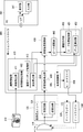
- FIG. 7 is a diagram representing the motion controller 400 as a functional block diagram. In FIG. 7, except for the motor driver, the function of the motion controller may be realized by the CPU loading a program.
- the motion controller 400 includes a central control unit 405, a motor driver 406, an image processing unit 410, a reception intensity detection unit 420, a reception intensity recording unit 430, a peak search unit 440, and an adjustment instruction unit 450. .
- the image processing unit 410 includes an image capturing unit 411, an initial image recording unit 412, an image matching processing unit 413, and a displacement calculation unit (position calculation unit) 414.
- the adjustment instruction unit 450 includes a peak position recording unit 451 and a deviation amount calculation unit 452. Detailed operation of each functional unit will be described later with reference to flowcharts and explanatory diagrams.
- FIG. 8 is a flowchart showing a series of procedures for adjusting the antenna direction to the optimum direction.
- the antenna orientation adjustment method can be roughly divided into a preparation step (ST100), a step of searching for an optimal reception direction (ST200), a step of adjusting the antenna orientation (ST300), and a step of fixing the antenna unit (ST400). And). These will be described in order.
- the preparation step (ST100) the step of temporarily installing the antenna device 100 (ST110), the step of attaching the camera 210 to the antenna device 100 (ST120), and the step of attaching the nut runner to the azimuth adjusting bolt 160 and the elevation angle adjusting bolt 180 (ST130), a step of connecting wiring (ST140), and a step of starting the motion controller (ST150).
- the step of temporarily installing the antenna device 100 is a step of installing the antenna device 100 at a predetermined installation location using the attachment means 130 as already shown in FIG.
- the orientation of the antenna unit 110 may be adjusted to a general direction and elevation angle.
- the direction of the antenna unit 110 is directed to the opposite station using a compass (azimuth magnetic needle) or the opposite station is confirmed using a scope and the direction of the antenna unit 110 is adjusted to the opposite station. Also good. Note that even if fine adjustment (ST300) is performed later, it is difficult to perform fine adjustment later if it is deviated by 10 ° or 20 °. It is necessary to align the directions of both antennas so that the received intensity level can be measured.
- the process of attaching the camera 210 (ST120) is also as already described with reference to FIG.
- the operator looks around and directs the camera 210 so that the building is reflected as much as possible, and then attaches the camera 210 to an appropriate position of the antenna device 100 in a fixed manner.
- the nut runners 220 and 230 are attached to the azimuth adjusting bolt 160 and the elevation angle adjusting bolt 180 (ST130). That is, the operator attaches the nut 221 of the nut runner 220 to the screw head of the orientation adjustment bolt 160 and attaches the nut 231 of the nut runner 230 to the screw head of the elevation adjustment bolt 180.
- wiring is connected to the motion controller 400 (ST140).
- the camera 210 and the motion controller 400 are connected. Furthermore, wiring is performed so that the motion controller 400 can detect the reception level of the antenna device 100.
- the reception circuit 121 of the transmission / reception unit 120 is connected to the motion controller 400.
- the nut runners 220 and 230 and the motion controller 400 are connected.
- the camera 210 and the motion controller 400 and the antenna device 100 and the motion controller 400 are connected by wired connection, but it is needless to say that wireless connection may be used.
- the nut runners 220 and 230 and the motion controller 400 may be wireless. In this case, a driver is built in the nut runners 220 and 230, and only the control signal may be transmitted from the motion controller 400 to the nut runners 220 and 230 wirelessly.
- the motion controller 400 is activated (ST140), and a predetermined program (antenna direction adjustment program) is loaded. This completes the preparation step (ST100).
- FIG. 9 shows details of the process for searching for the optimum reception direction (ST200). It is a flowchart which shows a simple procedure. The first thing to do is capture the initial image. When the camera 210 is already attached to the antenna apparatus 100, the image capturing unit 411 captures an image currently displayed on the camera 210 as an initial image (ST210).
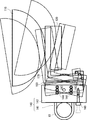
- FIG. 10 is a diagram illustrating a state in which the antenna device 100 is looked down from directly above.
- FIG. 10 is a view of the antenna device 100 viewed from the direction of the arrow II in FIG. 1.
- the imaging range of the camera 210 is indicated by a dotted line.
- the alternate long and short dash line indicates the center line of the imaging region.
- the building 20 is built closer to the center in the imaging range of the camera 210. That is, it is assumed that the building 20 is reflected closer to the center as shown in FIG.
- the image is displayed on the display unit 241 of the personal computer 240 via the image capturing unit 411.
- a display example in the display unit 241 is shown in order to visually indicate the processing by the motion controller 400 to the worker (and the reader of the present specification). However, since the antenna direction adjustment is automatically executed by the motion controller 400, there is essentially no need to display the processing contents one by one.
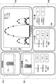
- FIG. 12 is an example of a display screen.
- the display screen is roughly divided into four areas, and the upper left area is an initial image display area R10 for displaying an initial image.
- the operator looks at the image displayed in the initial image display region R10 and confirms that an object (20) that is likely to be a mark is reflected.
- the initial image is recorded and recorded in the initial image recording unit 412.
- the central control unit 405 After capturing the initial image (ST210), the central control unit 405 performs a process of slightly changing the orientation of the antenna unit 110 (ST220). In this process (ST220), the central control unit 405 sends a control signal to the motor driver 406. The motor driver 406 sends a drive signal to the nut runners 220 and 230 according to the control signal.
- FIG. 13 is a diagram showing a state in which the orientation of the antenna unit 110 is slightly changed.
- the azimuth is changed by about 10 ° in FIG. 13 for easy understanding, but actually it is preferable to change the direction by a smaller angle (for example, about 0.1 °).)
- the orientation of the camera 210 changes in the same way as the antenna unit 110.
- the imaging direction of the camera 210 also changes.
- FIG. 14 it is assumed that the building 20 is displaced slightly to the left in the imaging region.
- the area below the initial image display area R10 is a current image display area R20 that displays a current image. The operator can view an image captured by the current camera 210 in a live manner in the current image display area R20.
- the image captured by the camera 210 after the orientation has been changed is taken as the current image.
- the image capturing unit 411 captures the current image (ST230).
- image processing unit 410 obtains how much the current image has shifted from the initial image by comparing the initial image with the current image (ST240). In this way, collating two images and recognizing how much one is misaligned with respect to the other is an application of pattern matching, and is realized by various methods. For example, a phase only correlation method is known.
- the image matching processing unit 413 compares the initial image P10 and the current image P20, and shifts the current image P20 so that the current image P20 most matches the initial image P10.
- FIG. 15 is a diagram illustrating a state in which the current image P20 is superimposed on the initial image P10 so that the two match. It is assumed that the building 20 that is slightly closer to the center in the initial image P10 is slightly leftward in the current image P20. In this case, it can be seen that the image center Oc of the current image P20 is displaced to the right with respect to the image center Oi of the initial image P10.
- the displacement calculation unit 414 calculates the amount of deviation of the current image P20 from the initial image P10 based on the matching result by the image matching processing unit 413 (ST240). Here, it is assumed that how many pixels are shifted in pixel units. As shown in FIG. 16, in the display image, the horizontal direction is the X-axis direction, and the vertical direction is the Y direction. The displacement calculation unit 414 calculates the amount of misalignment such that the current image P20 is displaced ( ⁇ X) pixels in the X direction with respect to the initial image P10 and how many ( ⁇ Y) pixels are displaced in the Y direction. The calculated deviation amounts ( ⁇ X, ⁇ Y) are displayed on the display screen. Here, it is assumed that the respective shift amounts in the x direction and the y direction are displayed below the current image display region R20 (see FIG. 12).
- the coordinates of the center Oc of the current image P20 can be represented by ( ⁇ X, ⁇ Y). Therefore, in this specification, the coordinate values ( ⁇ X, ⁇ Y) may be referred to as the position of the current image P20.
- the antenna unit 110 and the camera 210 have fixed positions and orientations. That is, the orientation of the antenna unit 110 and the image captured by the camera 210 when the antenna unit 110 is oriented have a one-to-one relationship.
- the orientation (angle) of the antenna unit 110 and the position ( ⁇ X, ⁇ Y) of the image are regarded as the same, and the coordinate values ( ⁇ X, ⁇ Y) may be referred to as the position of the antenna unit.
- the displacement calculation unit 414 may be referred to as a position calculation unit.
- reception intensity is detected (ST250). That is, the intensity of a signal that can be received in the current direction of the antenna unit 110 is detected.
- the radio wave signal received by the antenna unit 110 is sent to the reception intensity detection unit 420 via the transmission / reception unit 120 (reception circuit 121).
- the reception intensity detection unit 420 obtains the input signal level. Note that, in calculating the signal level, the reception intensity detection unit 420 performs time averaging processing. The reception strength obtained in this way is displayed on the display screen.
- a reception intensity display area is provided below the current image display area R20 together with the shift amount.
- the position of the current image P20 and the reception level at that time are recorded as a pair (ST260). That is, the position of the current image P20 calculated by the displacement calculation unit 414 and the reception intensity detected by the reception intensity detection unit 420 are sent to the reception intensity recording unit 430.
- the reception intensity recording unit 430 records the position of the current image P20 and the reception intensity as a pair.
- the position and reception intensity of the current image P20 are recorded and then displayed on the display screen as a graph.
- the upper right area of the display screen is the graph display area R30.
- the central control unit 405 repeats the steps from changing the antenna direction (ST220) to recording data (ST260) while changing the direction of the antenna unit 110 little by little.
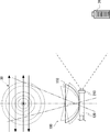
- FIG. 17 shows a state in which the direction of the antenna unit 110 is changed little by little together with an example of the reception antenna pattern 30 of the antenna device 100.
- the antenna unit 110 is a parabolic antenna
- the receiving antenna pattern 30 draws concentric circles.
- the central control unit 405 measures the reception level while variously changing the direction of the antenna unit 110 within a predetermined range. For example, raster scanning may be performed in a range of ⁇ 5 degrees in the azimuth angle range and ⁇ 5 degrees in the elevation angle range.
- the elevation angle is fixed to a certain value, and only the azimuth is swung from the left to the right. This means that the nut runner 220 is driven.
- the elevation angle is changed to a slightly smaller value (that is, the nut runner 230 is driven), and only the bearing is shaken from the right to the left (the nut runner 220 is driven).
- the direction of the antenna unit 110 is changed as indicated by the arrows C and D.
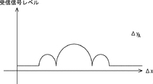
- FIG. 18 is a graph showing a change in received intensity when the direction of the antenna unit 110 is changed along the arrow A.
- the vertical axis represents the reception level and the horizontal axis represents the azimuth.
- the azimuth is represented by a value of ⁇ X.
- a label of ⁇ yA is attached to the right shoulder in FIG.
- FIG. 19 is a graph corresponding to the arrow B
- FIG. 20 is a graph corresponding to the arrow C.
- the graphs of FIGS. 18, 19 and 20 are displayed in the graph display region R30 of the display screen as shown in FIG.
- the peak position is searched (ST280).
- the peak search unit 440 searches for the maximum value of the reception intensity from the data recorded in the reception intensity recording unit 430.
- the peak search unit 440 finds the maximum value of the received intensity through the search, and further reads the position of the antenna unit 110 that realizes the maximum value of the received intensity. (Recall that the received intensity recording unit 430 records the position of the antenna unit 110 and the received intensity as a pair.)
- the maximum value of the received intensity and the position of the antenna unit 110 at that time ( ⁇ X , ⁇ Y) is displayed in the maximum reception direction display area R40 (ST290). As shown in FIG.
- the maximum reception direction display region R40 is arranged at the lower portion near the center of the display screen.
- the position of the antenna unit 110 that achieves the maximum value of the received intensity may be referred to as “peak position”.
- the peak position obtained by the peak search unit 440 is recorded in the peak position recording unit 451.
- the step of searching for the optimum reception direction ends.
- the process proceeds to the step of adjusting the orientation of the antenna unit 110 (ST300).
- a step of adjusting the orientation of the antenna unit 110 (ST300) will be described.
- the position (peak position) of the antenna unit 110 that has already achieved the maximum value of the reception intensity is already obtained.
- the motion controller 400 performs direction adjustment to match the direction of the antenna unit 110 with this peak position.
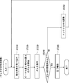
- FIG. 21 is a detailed flowchart of the step of adjusting the orientation of the antenna unit 110 (ST300).
- the image capturing unit 411 captures the current image (ST310). That is, in order to confirm the current antenna position, an image captured by the current camera 210 is acquired. Then, the deviation between the initial image and the current image is calculated by the image matching processing unit 413 and the displacement calculating unit 414 (ST320), and displayed together with the current image in the current image display region R20.
- the position ( ⁇ X, ⁇ Y) of the current image is sent to the deviation amount calculation unit 452.
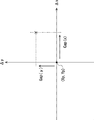
- the shift amount calculation unit 452 calculates how much the current image is shifted when the peak position is set as the origin. This situation is shown in FIG. In FIG. 22, the peak position is ( ⁇ Xp, ⁇ Yp), and this is set at the origin (Origin).
- the amount of deviation between the position ( ⁇ X, ⁇ Y) of the current image and the origin is defined as (Gap (x), Gap (y)).
- the deviation amounts (Gap (x), Gap (y)) thus obtained are displayed in the deviation amount display area R50 of the display screen (ST330).
- a shift amount display area R50 is provided on the right side of the maximum reception direction display area R40.
- the central control unit 405 determines whether or not the deviation is within an allowable range (ST340). (It is assumed that the allowable range is set in advance.) At the time of determination, not only the deviation values (Gap (x), Gap (y)) but also how much the current reception intensity is lower than the peak value is considered. Put in.
- the amount of deviation determined from the image varies depending on, for example, the distance from the camera 210 to the imaging target. Therefore, it is not preferable to simply use only the amount of deviation as an index. (The amount of deviation from 1 ° of the angle varies depending on the distance from the camera 210 to the imaging target.)
- the central control unit 405 adjusts the direction of the antenna unit 110 to be the peak position (ST350). (That is, the nut runners 220 and 230 are driven.) Then, it is evaluated again how much the adjusted position of the antenna unit 110 is deviated from the peak position (ST340), and the direction of the antenna unit 110 is the peak position. (ST350). (This is equivalent to performing feedback control using the camera 210 and the reception intensity detection unit 420 as sensors.) When it is determined that the deviation is within the allowable range (ST340: YES), the operator completes. Report (ST360). (The completion report method may be sound or message display on the display unit 241.)
- the image processing unit 410 is kept activated while the screws 144, 144, 173, and 173 are tightened, and ST310 to ST340 are repeated.
- ST340 allowable range
- the antenna direction adjusting device 200 is detached from the antenna device 100.
- the direction of the antenna unit 110 can be automatically adjusted to a direction in which the maximum reception level can be realized.
- the orientation of the antenna unit 110 has been adjusted with a handhold that relies on intuition, such as searching for a direction that can achieve the maximum reception level by trial and error, and repeating fine adjustments for going back and forth.
- the maximum reception level is obtained from the data recorded in the reception intensity recording unit 430, and the angle position (peak position) of the antenna unit 110 that realizes the maximum reception level is also obtained ( ST280). Further, how much the current antenna angle position is shifted in which direction with respect to the peak position is determined (ST420).
- the orientation of the antenna unit 110 is automatically adjusted. Therefore, according to the first embodiment, there is no need for trial and error, and there is no need for craftsmanship such as turning the adjustment bolt by a small amount with the sense of a fingertip, and any operator can install the antenna device 100 quickly and accurately. become able to.
- the angular position of the antenna unit 110 is obtained by comparing images captured by the camera 210.
- the imaging direction of the camera 210 is not limited to a specific direction. In other words, the antenna unit 110 and the camera 210 need not be aligned. Therefore, there is no need for costs and labor for attaching the camera 210 aligned with each antenna device 100.
- This embodiment is different from the type that uses the camera 210 as an aim. If the radio wave radiation direction is slightly deviated from the antenna surface, even if the antenna orientation is adjusted to face the antenna surface of the radio wave emission source, it will be the direction that achieves the maximum reception level. Not necessarily. In this regard, in the present embodiment, the direction of the antenna unit 110 is adjusted to the position where the radio wave reception level is maximized.
- a slight displacement of the antenna unit 110 can be detected by using the image of the camera 210.
- a rotary encoder in the movable part of the antenna device and detecting the direction of the antenna part based on the output value of the rotary encoder.
- the diameter of the rotary encoder in order to detect a rotation of less than 1 ° with a rotary encoder, the diameter of the rotary encoder must be several tens of centimeters. In other words, the antenna device becomes larger. Also, such a high precision rotary encoder is very expensive. Even if the orientation of the antenna unit is detected by the rotary encoder, a displacement transmission mechanism such as a gear is always required between the rotary encoder and the antenna unit. Then, an error due to backlash is inevitably generated between the gears.
- the configuration using the camera 210 as in the present embodiment it is inexpensive and completely unrelated to the increase in the size of the antenna device 100. Further, as the distance from the camera 210 to the imaging target increases, the positional deviation of the imaging target with respect to the angle change of the camera 210 increases. Therefore, by using the image of the camera 210, the displacement of the camera 210 (that is, the antenna unit 110) can be detected with extremely high resolution. And since the position (displacement) of the antenna unit 110 itself is measured by the camera 210, there is no room for backlash to occur in the middle. (In essence, this is equivalent to attaching a displacement sensor to the object itself to be direction-adjusted.) As described above, since the direction of the antenna unit can be measured directly, extremely accurate direction adjustment can be realized.
- the antenna device is installed at a high place or a place with a good view for convenience of transmitting and receiving radio waves. Therefore, when the camera 210 is attached to the antenna device 100, the camera 210 can automatically shoot far away. That is, using the camera 210 to detect the orientation of the antenna unit 110 has a special effect. If it is an environment where only close-up shooting is possible, it will be necessary to use an ultra-high-precision optical system that eliminates aberrations and distortions in order to detect minute displacements by image processing. In this case, general digital is not enough. In this regard, as in the present embodiment, when the camera 210 is used for adjusting the orientation of the antenna unit 110, a distant view can be taken almost certainly, so that even the performance of the inexpensive camera 210 can sufficiently satisfy the requirements.
- the present invention is not limited to the above-described embodiment, and can be changed as appropriate without departing from the spirit of the present invention.
- the peak position search method may have various other variations.
- FIG. 23 there is a method of driving the peak position while alternately scanning the EL direction and the AZ direction.
- the EL direction is scanned along a certain line, and the peak direction is obtained on the line.
- the EL is aligned with the peak direction, and scanning is performed along the line in the AZ direction. If this operation is repeated, the peak position can be determined. (In other words, this method is almost equivalent to performing ST200 and ST300 alternately.)
- the central control unit 405, the image processing unit 410, the reception intensity detection unit 420, the reception intensity recording unit 430, the peak search unit 440, and the adjustment instruction unit 450 are each dedicated hardware composed of various logic elements and the like. It may be. Alternatively, a predetermined program is incorporated into a computer having a CPU (central processing unit) and a memory (storage device), and the central control unit 405, image processing unit 410, reception intensity detection unit 420, reception intensity recording unit 430, peak search. Each function of the unit 440 and the adjustment instruction unit 450 may be realized.
- an antenna direction adjustment program is installed in the memory via a communication means such as the Internet or a non-volatile recording medium such as a CD-ROM or a memory card. It is only necessary to operate and realize each of the functional units.
- a memory card, a CD-ROM or the like may be directly inserted into the computer, or a device for reading these storage media may be connected to the computer externally.
- a LAN cable, a wired or wireless communication line may be connected to a computer, and the program may be supplied and installed by communication.
- the orientation adjustment bolt 160 and the elevation angle adjustment bolt 180 are illustrated as the orientation adjustment parts.
- a screw is used as the orientation adjusting component, and when the antenna unit is moved, the advancement / retraction of the screw by rotation will be used.
- the present invention is not limited to this, and any configuration is possible as long as the orientation of the antenna unit can be changed. For example, it can be realized by various combinations of cams and gears.
- a nut runner is illustrated as an electric part because the direction adjustment part is a bolt. However, if the direction adjustment part is replaced with another one, it is natural to change the electric part so as to match it. .
- the azimuth angle and elevation angle can be varied with a single orientation adjustment component.
- Such an antenna device is disclosed in, for example, Japanese Patent Laid-Open No. 5-67909. In this case, needless to say, only one electric part (nut runner) is required.
- FIG. 24 shows an antenna system in which an antenna device and an antenna direction adjusting device are integrated.
- the antenna system is installed on the installation surface of the installation table 60.
- the antenna system has a configuration in which the antenna unit 110 is supported by a pan head 520.
- the camera platform 520 is supported by the base 521, the swivel base 522 that is turnably supported by the base 521, the turning motor 524 that drives the turntable 522 to turn, and the turntable 522 that is rotatable in the elevation direction.
- the rotating table 523 includes a rotating motor 525 that rotates the rotating table 523.
- a control unit 540 and an antenna unit 110 are supported on the turntable 523.
- the control unit 540 includes the power transmission / reception unit 120 and the motion controller 400. (In this case, the pan head is the orientation adjustment component.) If the motor is built in as an antenna system, the nut runner need not be attached or removed.
- Elevation angle adjustment bolt 200 ... Antenna direction adjustment device, 210 ... Camera, 220, 230 ... Nut runner, 220 ... Jig, 221 ... Nut, 222 ... Large gear, 223 ... Pinion, 224 ... Motor, 225 ... Case, 240 ... PC, 241 ... Display unit, 400 ... Motion controller, 405 ... Central control unit 406 ... Motor driver, 410 ... Image processing unit, 411 ... Image capture unit, 412 ... Initial image recording unit, 413 ... Image matching processing unit, 414 ... Displacement calculation unit, 420 ... Reception intensity detection unit, 430 ... Reception intensity recording 440 ... peak search unit 450 ... adjustment instruction unit 451 ... peak position recording unit 452 ... deviation amount calculation unit.
Landscapes
- Physics & Mathematics (AREA)
- Electromagnetism (AREA)
- Engineering & Computer Science (AREA)
- Computer Networks & Wireless Communication (AREA)
- Signal Processing (AREA)
- Variable-Direction Aerials And Aerial Arrays (AREA)
Abstract
Description
しかしながら、アンテナの方向調整としては仰角と方位との二方向を合わせる必要があるところ、最大受信レベルを達成できる方向へアンテナの向きを合わせるのは現実的にはかなり難しい。受信レベルを逐一確認しながら仰角と方位とを様々に微調整し、行きつ戻りつを繰り返して最大受信レベルになる向きにアンテナを合わせるのは相当に時間のかかる作業になる。
まず第1に、アンテナの受信方向に対してカメラの光軸を高い精度でアライメントするのは容易なことではない。アライメント誤差は1.0°未満でなければならないが、アンテナの設置現場でアンテナの受信方向とカメラの光軸とをこのような高精度にアライメントすることは手動では無理である。したがって、アンテナメーカとしては、アライメントされたカメラを付属した状態でアンテナ装置を製造販売することになるが、各アンテナにカメラを付属させるとなると相当のコスト増になる。
第3には、電波発生源からの電波放射方向が電波発射源のアンテナ面に対して垂直になっているとは限らないという問題がある。電波放射方向がアンテナ面に対してわずかでもずれていたとすると、電波発射源のアンテナ面に対して正対するようにアンテナの向きを調整したとしても、それが最大受信レベルを実現する方向になっているとは全く限らないのである。
アンテナ部と前記アンテナ部の向きを変える向き調整用部品とを有するアンテナ装置の前記アンテナ部の向きを調整するアンテナ方向調整装置であって、
前記アンテナ部に対して相対的に固定されるカメラと、
前記向き調整部品に取り付け可能であるとともに、モータの動力を前記向き調整用部品に力を印加して前記アンテナ部の向きを変更する電動部と、
前記電動部に駆動信号を与えて前記アンテナ部の向きを調整するモーションコントローラと、を備え、
前記モーションコントローラは、
前記カメラで撮像された画像と前記アンテナ部で受信された電波の受信強度とに基づいて前記アンテナ部の角度位置を求め、前記電動部に駆動信号を与えて、前記アンテナ部の角度位置を調整する
ことを特徴とする。
アンテナ部と前記アンテナ部の向きを変える向き調整用部品とを有するアンテナ装置の前記アンテナ部の向きを調整するアンテナ方向調整方法であって、
前記アンテナ装置のアンテナ部に対して位置および向きが相対変位しないように前記アンテナ装置にカメラを取り付ける工程と、
前記向き調整用部品に電動部を取り付ける工程と、
前記カメラで撮像された画像と前記アンテナ部で受信された電波の受信強度とに基づいて受信強度が最大となる前記アンテナ部の角度位置を求める工程と、
前記電動部に駆動信号を与えて、前記アンテナ部の角度位置を調整する工程と、を備える
ことを特徴とする。
(第1実施形態)
本発明の第1実施形態について説明する。
本実施形態の主たるポイントは、アンテナの方向を調整するアンテナ方向調整装置の構成およびその動作にある。とはいえ、アンテナ方向の調整について説明する前に、アンテナ装置100の構成について概略説明しておく。
図1は、アンテナ装置100を示す図である。アンテナ装置100自体は既知のものでよい。ここでは、いわゆるパラボラアンテナを例示しているが、本実施形態を適用するにあたってアンテナの種類は特に限定されない。指向性のアンテナとして、例えば、平面アンテナであってもよい。
ここでは、アンテナ装置100の一般的な設置状態を念頭において回動軸の軸線方向を説明することとする。ただし、アンテナ部110を動かせる自由度としては独立回転可能な二軸があればいいのであり、鉛直や水平といった重力方向にとらわれる必要は全く無い。
アンテナ部110は仰角方向可動金具170の先端に連結されているので、仰角方向可動金具170とともにアンテナ部110の仰角を変更することができる。このとき、仰角調整ボルト180を回転操作すればよい。さらに、仰角方向可動金具170の基端171は方位方向可動金具150に取り付けられているので、仰角方向可動金具170およびアンテナ部110は、方位方向可動金具150とともに方位を変えることができる。このとき、方位調整ボルト160を回転操作すればよい。
図4は、アンテナ方向調整装置200をアンテナ装置100に付設した状態を示す図である。
アンテナ方向調整装置200は、カメラ210と、2つのナットランナー(電動部)220、230と、モーションコントローラ400と、パソコン(パーソナルコンピュータ)240と、を備える。このようにアンテナ方向調整装置200をアンテナ装置100に付設した状態をアンテナシステムと称することにする。
以下、説明する。
図6で分かるように、ボルト160、180の進退を許容できるように、ナット221の孔はやや深くなっている。
これにより、ボルト160、180のネジ頭とナット221の底面とが干渉することを回避する。
調整指示部450は、ピーク位置記録部451と、ズレ量算出部452と、を備える。
各機能部の詳しい動作は、フローチャートおよび説明図を参照しながら後述する。
アンテナ向き調整方法は、大まかに分けると、準備工程(ST100)と、最適受信方向を探索する工程(ST200)と、アンテナ向きを調整する工程(ST300)と、アンテナ部装置を固定する工程(ST400)と、を備える。
順に説明する。
この際には、アンテナ部110の向きは、大凡の方位および仰角に調整しておけばよい。
例えば、コンパス(方位磁針)を利用してアンテナ部110の向きを対向局の方向に向けたり、スコープを用いて対向局を確認してからアンテナ部110の向きをこの対向局に合わせたりしてもよい。
なお、後に微調整(ST300)するとはいっても、10°も20°もずれていては後の微調整が困難である。
受信強度レベルを測定できる程度には双方のアンテナの向きを合わせておく必要がある。
アンテナの口径や性能などにもよるが、例えば、最適と思われる方向に対して前後5°程度の範囲に収まるようにはしたい。
ちなみに一般的にいって、通信に必要な受信強度と、受信強度をなんとか測定できる程度の受信強度と、の間には20dBから30dB程度の差がある。
さらには、ナットランナー220、230とモーションコントローラ400との間も無線にしてもよい。
この場合は、ナットランナー220、230の方にドライバを内蔵しておき、モーションコントローラ400からナットランナー220、230へは制御信号だけ無線で送るようにすればよい。
以上で、準備工程(ST100)は終了である。
すなわち、現在のアンテナ部110の方向で受信できる信号の強度を検出する。
アンテナ部110で受信された電波信号は、送受信ユニット120(受信回路121)を介して受信強度検出部420に送られる。
受信強度検出部420は、入力された信号レベルを求める。
なお、信号レベルの算出にあたっては、受信強度検出部420は時間平均化処理を行う。
このようにして求められた受信強度は表示画面に表示される。
ここでは、現在画像表示領域R20の下に、ズレ量と合わせて受信強度の表示領域が設けられているとする。
ここでは、表示画面のうち右上の領域がグラフ表示領域R30であるとする。
次に、アンテナ部110の向きを調整する工程(ST300)に移行する。
最適受信方向を探索する工程(ST200)においてすでに受信強度の最大値を実現するアンテナ部110の位置(ピーク位置)が求められているところ、アンテナ部110の向きを調整する工程(ST300)では、モーションコントローラ400はアンテナ部110の向きをこのピーク位置に合わせる方向調整を行う。
(1)本実施形態によれば、アンテナ部110の向きを最大受信レベルが実現できる向きに自動的に調整できる。従来は、試行錯誤によって最大受信レベルを実現できる方角を探りあてたり、行きつ戻りつの微調整を繰り返したりするなど、まさに勘に頼った手さぐりでアンテナ部110の向きを調整していた。
この点、本第1実施形態では、受信強度記録部430に記録したデータのなかから最大受信レベルを求め、あわせて、最大受信レベルを実現するアンテナ部110の角度位置(ピーク位置)を求める(ST280)。
さらに、現在のアンテナ角度位置がピーク位置に対してどの方向にどの程度ズレているかを求める(ST420)。そして、ナットランナー220、230によってボルト160、180を回すことで(ST350)、自動的にアンテナ部110の向きを調整する。したがって、本第1実施形態によれば、試行錯誤も必要無いし、指先の感覚で調整ボルトを微少量だけ回すといった職人芸も必要なく、どんな作業者でも、アンテナ装置100を素早くかつ正確に設置できるようになる。
ピーク位置の探索においては図17のように全体をラスタースキャンしてもよいが、ピーク位置探索の方法は他にも種々のバリエーションが有り得る。一例だけ挙げておく。例えば、図23のように、EL方向とAZ方向とを交互にスキャンしながらピーク位置を追い込んでいく方法がある。この方法においては、(1)あるラインに沿ってEL方向をスキャンして、そのライン上でピーク方向を求める。(2)次に、そのピーク方向にELを合わせて、AZ方向にラインに沿ってスキャンする。この動作を繰り返していけば、ピーク位置を追い込んで求めることができる。
(言い方と変えると、このやり方は、ST200とST300とを交互に行っていることにほぼ等しい。)
プログラムをインストールするにあたっては、メモリカードやCD-ROM等をコンピュータに直接差し込んで行ってもよいし、これらの記憶媒体を読み取る機器を外付けでコンピュータに接続してもよい。さらには、LANケーブル、有線または無線の通信回線をコンピュータに接続して通信によってプログラムを供給しインストールしてもよい。
向き調整用部品としてはネジを用い、アンテナ部を動かすに当たっては回転によるネジの進退を利用するのが一般的であろう。しかし、これに限定されないのはもちろんであり、アンテナ部の向きを変更できる構成であれば、何でもよい。例えばカムや歯車を様々に組み合わせることで実現できるであろう。
同様に、向き調整用部品をボルトとしたので電動部としてナットランナーを例示したが、向き調整用部品が別のものに置換されればそれに適合するように電動部を変更するのは当然である。
Claims (6)
- アンテナ部に対して相対的に固定されるカメラと、
向き調整部品に取り付け可能であるとともに、モータの動力を前記向き調整用部品に力を印加して前記アンテナ部の向きを変更する電動部と、
前記電動部に駆動信号を与えて前記アンテナ部の向きを調整するモーションコントローラと、を備え、
前記モーションコントローラは、
前記カメラで撮像された画像と前記アンテナ部で受信された電波の受信強度とに基づいて前記アンテナ部の角度位置を求め、前記電動部に駆動信号を与えて、前記アンテナ部の角度位置を調整する
ことを特徴とするアンテナ方向調整装置。 - 請求項1に記載のアンテナ方向調整装置において、
前記モーションコントローラは、
前記電動部に駆動信号を与えることで前記アンテナ部の方向を所定範囲内で変えながら前記アンテナ部の方向と受信強度との関係を取得する
ことを特徴とするアンテナ方向調整装置。 - 請求項1または請求項2に記載のアンテナ方向調整装置において、
前記モーションコントローラは、
前記カメラで撮像された画像と前記アンテナ部で受信された電波の受信強度とに基づいて受信強度が最大となる前記アンテナ部の角度位置を求め、前記電動部に駆動信号を与えて、前記アンテナ部を受信強度が最大となる角度位置に調整する
ことを特徴とするアンテナ方向調整装置。 - 請求項1から請求項3のいずれかに記載のアンテナ方向調整装置において、
前記モーションコントローラは、
前記カメラで撮像された画像を用いて前記アンテナ部の相対角度位置を算出する位置算出部と、
前記アンテナ部にて受信された電波の受信強度を検出する受信強度検出部と、
前記アンテナ部の相対角度位置とその相対角度位置のときの前記受信強度とを対応付けて記録する受信強度記録部と、
前記受信強度記録部に記録されているデータのなかから受信強度の最大値を探索するピーク探索部と、
前記ピーク探索部によって求められた最大受信強度に対応するアンテナ部の角度位置をピーク位置として記録するピーク位置記録部と、
現在の前記アンテナ部の角度位置と前記ピーク位置とのズレ量を算出するズレ量算出部と、を備え、
前記ズレ量がゼロに近づくように前記電動部に駆動信号を与える
ことを特徴とするアンテナ方向調整装置。 - 向き調整用部品に力を加えることでアンテナ部の向きを変えられるようになっているアンテナ装置と、請求項1から請求項4のいずれかに記載のアンテナ方向調整装置と、を具備するアンテナシステム。
- アンテナ装置のアンテナ部に対して位置および向きが相対変位しないように前記アンテナ装置にカメラを取り付ける工程と、
向き調整用部品に電動部を取り付ける工程と、
前記カメラで撮像された画像と前記アンテナ部で受信された電波の受信強度とに基づいて前記アンテナ部の角度位置を求める工程と、
前記電動部に駆動信号を与えて、前記アンテナ部の角度位置を調整する工程と、を備える
ことを特徴とするアンテナ方向調整方法。
Priority Applications (4)
| Application Number | Priority Date | Filing Date | Title |
|---|---|---|---|
| EP15745964.5A EP3104459A4 (en) | 2014-02-04 | 2015-01-08 | Antenna-direction adjusting device and antenna-direction adjusting method |
| CN201580006943.8A CN105981221A (zh) | 2014-02-04 | 2015-01-08 | 天线方位调节装置及天线方位调节方法 |
| US15/115,732 US10044093B2 (en) | 2014-02-04 | 2015-01-08 | Antenna orientation adjustment device and antenna orientation adjustment method |
| ZA2016/05346A ZA201605346B (en) | 2014-02-04 | 2016-08-02 | Antenna-orientation adjustment device and antenna orientation adjustment method. |
Applications Claiming Priority (2)
| Application Number | Priority Date | Filing Date | Title |
|---|---|---|---|
| JP2014019265 | 2014-02-04 | ||
| JP2014-019265 | 2014-02-04 |
Publications (1)
| Publication Number | Publication Date |
|---|---|
| WO2015118796A1 true WO2015118796A1 (ja) | 2015-08-13 |
Family
ID=53777611
Family Applications (1)
| Application Number | Title | Priority Date | Filing Date |
|---|---|---|---|
| PCT/JP2015/000057 Ceased WO2015118796A1 (ja) | 2014-02-04 | 2015-01-08 | アンテナ方向調整装置およびアンテナ方向調整方法 |
Country Status (5)
| Country | Link |
|---|---|
| US (1) | US10044093B2 (ja) |
| EP (1) | EP3104459A4 (ja) |
| CN (1) | CN105981221A (ja) |
| WO (1) | WO2015118796A1 (ja) |
| ZA (1) | ZA201605346B (ja) |
Cited By (4)
| Publication number | Priority date | Publication date | Assignee | Title |
|---|---|---|---|---|
| JP2016092704A (ja) * | 2014-11-08 | 2016-05-23 | 株式会社松浦機械製作所 | アンテナ取付・方向調整装置およびアンテナ取付・方向調整方法 |
| CN112968265A (zh) * | 2021-02-03 | 2021-06-15 | 浙江金乙昌科技股份有限公司 | 一种小型化低剖面的导航组合天线结构及其组装方法 |
| JP2022071444A (ja) * | 2020-10-28 | 2022-05-16 | 株式会社日立ビルシステム | 駆動機構システム |
| CN116647772A (zh) * | 2023-07-06 | 2023-08-25 | 黑龙江凯程通信技术有限责任公司 | 一种基于聚类分析的5g基站节能装置 |
Families Citing this family (22)
| Publication number | Priority date | Publication date | Assignee | Title |
|---|---|---|---|---|
| MX2015003533A (es) * | 2012-09-20 | 2015-09-08 | Nec Corp | Dispositivo de asistencia de orientacion de antena y metodo de instalacion de dispositivo de antena. |
| EP3264642A4 (en) | 2015-02-27 | 2018-01-10 | Nec Corporation | Display apparatus, image generation apparatus, communication apparatus, communication system, antenna adjusting method, image generation method and non-transitory computer readable medium in which program is stored |
| JP6157683B1 (ja) * | 2016-04-28 | 2017-07-05 | 三菱電機株式会社 | 波動エネルギー放射装置 |
| US20190148813A1 (en) * | 2016-07-13 | 2019-05-16 | Tomer Bruchiel | Imaging system and method for accurately directing antennas |
| US10283850B2 (en) | 2017-03-27 | 2019-05-07 | Intel Corporation | Wireless wearable devices having self-steering antennas |
| US10267888B2 (en) * | 2017-04-28 | 2019-04-23 | Higher Ground Llc | Pointing an antenna at a signal source using augmented reality |
| US10116893B1 (en) * | 2017-04-28 | 2018-10-30 | Higher Ground Llc | Selectively controlling a direction of signal transmission using adaptive augmented reality |
| CN107360094B (zh) * | 2017-07-31 | 2021-03-09 | 台州市吉吉知识产权运营有限公司 | 一种路由器天线调节方法及装置 |
| CN109101044A (zh) * | 2018-08-03 | 2018-12-28 | 广州瀚信通信科技股份有限公司 | 一种基于物联网技术的天线信息采集及调整系统 |
| CN109149112B (zh) * | 2018-09-04 | 2024-03-26 | 昆山市联升机电有限公司 | 天线调整装置及其系统 |
| CN109244635B (zh) * | 2018-11-21 | 2023-08-01 | 泰州市柯普尼通讯设备有限公司 | 高速缓存式船载天线装置及其使用方法 |
| CN109977710B (zh) * | 2019-02-18 | 2024-02-06 | 广东智媒云图科技股份有限公司 | 一种精准定位图书所属书架的方法、电子设备及存储介质 |
| KR102168448B1 (ko) * | 2019-11-18 | 2020-10-21 | 위월드 주식회사 | 스탠드형 포터블 안테나 |
| CN111224211A (zh) * | 2020-01-10 | 2020-06-02 | 四川豪威尔信息科技有限公司 | 一种5g基站天线仰角调控机构 |
| EP4097877B1 (en) | 2020-01-27 | 2025-07-16 | Telefonaktiebolaget LM Ericsson (PUBL) | Means and method for microwave radio transceiver control |
| CN112367092B (zh) * | 2020-11-10 | 2021-12-10 | 广东信测科技有限公司 | 一种节能型防干扰5g信号接收装置 |
| CA3140652A1 (en) * | 2020-11-30 | 2022-05-30 | Multiwave Sensors Inc. | Camera in bracket and method to minimize blind spots to the transmission of antenna signals |
| CN114978369B (zh) * | 2021-02-25 | 2024-08-30 | 浙江宇视科技有限公司 | 天线的位置调节方法、装置、电子设备及计算机存储介质 |
| JP7612503B2 (ja) * | 2021-04-26 | 2025-01-14 | 株式会社Nhkテクノロジーズ | 無線回線可視化装置及び無線回線可視化方法 |
| JP7710180B2 (ja) * | 2021-06-23 | 2025-07-18 | パナソニックIpマネジメント株式会社 | 通信システム、無線接続方法、及び、無線装置 |
| CN114325680B (zh) * | 2021-12-27 | 2025-04-08 | 北京源清慧虹信息科技有限公司 | 一种毫米波雷达中的主动机动距测方法 |
| WO2024192421A1 (en) * | 2023-03-16 | 2024-09-19 | Viasat, Inc. | Camera assisted antenna pointing |
Citations (2)
| Publication number | Priority date | Publication date | Assignee | Title |
|---|---|---|---|---|
| JPH09232847A (ja) * | 1996-02-26 | 1997-09-05 | Nippon Columbia Co Ltd | 受信装置 |
| JP2000315907A (ja) * | 1999-04-28 | 2000-11-14 | Nippon Hoso Kyokai <Nhk> | アンテナ方向調整装置 |
Family Cites Families (11)
| Publication number | Priority date | Publication date | Assignee | Title |
|---|---|---|---|---|
| US6587699B2 (en) | 2001-05-02 | 2003-07-01 | Trex Enterprises Corporation | Narrow beamwidth communication link with alignment camera |
| JP2005072780A (ja) | 2003-08-21 | 2005-03-17 | Hitachi Kokusai Electric Inc | アンテナ方向調整方法 |
| JP4764089B2 (ja) | 2005-07-29 | 2011-08-31 | 株式会社東芝 | 可搬式方探装置 |
| JP4696806B2 (ja) * | 2005-09-20 | 2011-06-08 | 日本電信電話株式会社 | アンテナ方向調整方法 |
| US9246207B2 (en) | 2005-09-22 | 2016-01-26 | Purdue Research Foundation | Antenna aiming system and method for broadband wireless access |
| US8239083B2 (en) * | 2006-01-18 | 2012-08-07 | I-Guide Robotics, Inc. | Robotic vehicle controller |
| US8451171B1 (en) | 2008-08-05 | 2013-05-28 | The Directv Group, Inc. | Tool to automatically align outdoor unit |
| CN102187597B (zh) * | 2008-08-20 | 2014-09-10 | 株式会社Kmw | 用于移动通信基站的天线的控制系统和图像数据提供系统以及使用该控制系统的方法 |
| US9046601B2 (en) * | 2009-06-15 | 2015-06-02 | Hendrikus A. Le Sage | Handheld antenna attitude measuring system |
| JP2011151722A (ja) * | 2010-01-25 | 2011-08-04 | Nippon Telegr & Teleph Corp <Ntt> | 無線装置、無線システム、およびアンテナ追尾方法 |
| US9502764B2 (en) * | 2014-06-05 | 2016-11-22 | T-Mobile Usa, Inc. | Autonomous antenna tilt compensation |
-
2015
- 2015-01-08 WO PCT/JP2015/000057 patent/WO2015118796A1/ja not_active Ceased
- 2015-01-08 US US15/115,732 patent/US10044093B2/en not_active Expired - Fee Related
- 2015-01-08 CN CN201580006943.8A patent/CN105981221A/zh active Pending
- 2015-01-08 EP EP15745964.5A patent/EP3104459A4/en not_active Withdrawn
-
2016
- 2016-08-02 ZA ZA2016/05346A patent/ZA201605346B/en unknown
Patent Citations (2)
| Publication number | Priority date | Publication date | Assignee | Title |
|---|---|---|---|---|
| JPH09232847A (ja) * | 1996-02-26 | 1997-09-05 | Nippon Columbia Co Ltd | 受信装置 |
| JP2000315907A (ja) * | 1999-04-28 | 2000-11-14 | Nippon Hoso Kyokai <Nhk> | アンテナ方向調整装置 |
Non-Patent Citations (1)
| Title |
|---|
| See also references of EP3104459A4 * |
Cited By (7)
| Publication number | Priority date | Publication date | Assignee | Title |
|---|---|---|---|---|
| JP2016092704A (ja) * | 2014-11-08 | 2016-05-23 | 株式会社松浦機械製作所 | アンテナ取付・方向調整装置およびアンテナ取付・方向調整方法 |
| JP2022071444A (ja) * | 2020-10-28 | 2022-05-16 | 株式会社日立ビルシステム | 駆動機構システム |
| JP7554633B2 (ja) | 2020-10-28 | 2024-09-20 | 株式会社日立ビルシステム | 駆動機構システム |
| CN112968265A (zh) * | 2021-02-03 | 2021-06-15 | 浙江金乙昌科技股份有限公司 | 一种小型化低剖面的导航组合天线结构及其组装方法 |
| CN112968265B (zh) * | 2021-02-03 | 2022-06-17 | 浙江金乙昌科技股份有限公司 | 一种小型化低剖面的导航组合天线结构及其组装方法 |
| CN116647772A (zh) * | 2023-07-06 | 2023-08-25 | 黑龙江凯程通信技术有限责任公司 | 一种基于聚类分析的5g基站节能装置 |
| CN116647772B (zh) * | 2023-07-06 | 2023-11-17 | 黑龙江凯程通信技术有限责任公司 | 一种5g基站节能装置 |
Also Published As
| Publication number | Publication date |
|---|---|
| ZA201605346B (en) | 2017-09-27 |
| EP3104459A4 (en) | 2017-09-06 |
| US10044093B2 (en) | 2018-08-07 |
| US20170179566A1 (en) | 2017-06-22 |
| EP3104459A1 (en) | 2016-12-14 |
| CN105981221A (zh) | 2016-09-28 |
Similar Documents
| Publication | Publication Date | Title |
|---|---|---|
| WO2015118796A1 (ja) | アンテナ方向調整装置およびアンテナ方向調整方法 | |
| WO2014045495A1 (ja) | アンテナ向き調整支援装置およびアンテナ装置設置方法 | |
| EP3677872B1 (en) | Surveying instrument | |
| JP4177765B2 (ja) | 測量システム | |
| US9958268B2 (en) | Three-dimensional measuring method and surveying system | |
| US9989632B2 (en) | Measuring system, and portable radio transceiver and measurement pole used in measuring system | |
| US9658335B2 (en) | Measurement system with a measuring device and a scanning module | |
| EP1903304B1 (en) | Position measuring system, position measuring method and position measuring program | |
| CN106197385B (zh) | 测量装置 | |
| US10469754B2 (en) | Position guiding device, position guiding method, and position guiding program | |
| CN105318864B (zh) | 测量装置 | |
| US10330788B2 (en) | Measuring instrument | |
| CN113155100B (zh) | 大地测量仪器、其基座模块及勘测和/或投影模块 | |
| KR101740994B1 (ko) | 인접면들의 에지들 및 코너들을 추적, 측정 및 마킹하기 위한 구조 측정 유닛 | |
| CN106716061A (zh) | 测设信息标示装置、测设信息标示方法 | |
| JP7311342B2 (ja) | 3次元測量装置、3次元測量方法および3次元測量プログラム | |
| WO2015129153A1 (ja) | アンテナ装置およびアンテナ装置の制御方法 | |
| JP7448397B2 (ja) | 測量装置及び測量システム | |
| JP2007120993A (ja) | 物体形状測定装置 | |
| KR101809655B1 (ko) | 공간영상도화 데이터 이미지를 입체적 이미지로 확보하는 시스템 | |
| JP2018066623A (ja) | 反射ターゲット及び反射ターゲットの調整方法 | |
| JP5863482B2 (ja) | 角度測定装置 | |
| CN219871792U (zh) | 激光雷达发射角度标定设备 | |
| JP2021127801A (ja) | 三脚及び測量装置 | |
| JP2017223608A (ja) | 測量装置 |
Legal Events
| Date | Code | Title | Description |
|---|---|---|---|
| 121 | Ep: the epo has been informed by wipo that ep was designated in this application |
Ref document number: 15745964 Country of ref document: EP Kind code of ref document: A1 |
|
| WWE | Wipo information: entry into national phase |
Ref document number: 15115732 Country of ref document: US |
|
| NENP | Non-entry into the national phase |
Ref country code: DE |
|
| REEP | Request for entry into the european phase |
Ref document number: 2015745964 Country of ref document: EP |
|
| WWE | Wipo information: entry into national phase |
Ref document number: 2015745964 Country of ref document: EP |
|
| NENP | Non-entry into the national phase |
Ref country code: JP |