WO2015118874A1 - ネットワークシステム、ネットワーク制御方法および制御装置 - Google Patents
ネットワークシステム、ネットワーク制御方法および制御装置 Download PDFInfo
- Publication number
- WO2015118874A1 WO2015118874A1 PCT/JP2015/000525 JP2015000525W WO2015118874A1 WO 2015118874 A1 WO2015118874 A1 WO 2015118874A1 JP 2015000525 W JP2015000525 W JP 2015000525W WO 2015118874 A1 WO2015118874 A1 WO 2015118874A1
- Authority
- WO
- WIPO (PCT)
- Prior art keywords
- network
- server
- path
- virtual
- information
- Prior art date
- Legal status (The legal status is an assumption and is not a legal conclusion. Google has not performed a legal analysis and makes no representation as to the accuracy of the status listed.)
- Ceased
Links
Images










Classifications
-
- H—ELECTRICITY
- H04—ELECTRIC COMMUNICATION TECHNIQUE
- H04L—TRANSMISSION OF DIGITAL INFORMATION, e.g. TELEGRAPHIC COMMUNICATION
- H04L12/00—Data switching networks
- H04L12/64—Hybrid switching systems
- H04L12/6418—Hybrid transport
-
- H—ELECTRICITY
- H04—ELECTRIC COMMUNICATION TECHNIQUE
- H04L—TRANSMISSION OF DIGITAL INFORMATION, e.g. TELEGRAPHIC COMMUNICATION
- H04L41/00—Arrangements for maintenance, administration or management of data switching networks, e.g. of packet switching networks
- H04L41/12—Discovery or management of network topologies
- H04L41/122—Discovery or management of network topologies of virtualised topologies, e.g. software-defined networks [SDN] or network function virtualisation [NFV]
-
- H—ELECTRICITY
- H04—ELECTRIC COMMUNICATION TECHNIQUE
- H04L—TRANSMISSION OF DIGITAL INFORMATION, e.g. TELEGRAPHIC COMMUNICATION
- H04L41/00—Arrangements for maintenance, administration or management of data switching networks, e.g. of packet switching networks
- H04L41/22—Arrangements for maintenance, administration or management of data switching networks, e.g. of packet switching networks comprising specially adapted graphical user interfaces [GUI]
-
- H—ELECTRICITY
- H04—ELECTRIC COMMUNICATION TECHNIQUE
- H04L—TRANSMISSION OF DIGITAL INFORMATION, e.g. TELEGRAPHIC COMMUNICATION
- H04L43/00—Arrangements for monitoring or testing data switching networks
- H04L43/08—Monitoring or testing based on specific metrics, e.g. QoS, energy consumption or environmental parameters
- H04L43/0805—Monitoring or testing based on specific metrics, e.g. QoS, energy consumption or environmental parameters by checking availability
-
- H—ELECTRICITY
- H04—ELECTRIC COMMUNICATION TECHNIQUE
- H04L—TRANSMISSION OF DIGITAL INFORMATION, e.g. TELEGRAPHIC COMMUNICATION
- H04L43/00—Arrangements for monitoring or testing data switching networks
- H04L43/08—Monitoring or testing based on specific metrics, e.g. QoS, energy consumption or environmental parameters
- H04L43/0876—Network utilisation, e.g. volume of load or congestion level
- H04L43/0894—Packet rate
-
- H—ELECTRICITY
- H04—ELECTRIC COMMUNICATION TECHNIQUE
- H04L—TRANSMISSION OF DIGITAL INFORMATION, e.g. TELEGRAPHIC COMMUNICATION
- H04L45/00—Routing or path finding of packets in data switching networks
- H04L45/02—Topology update or discovery
- H04L45/036—Updating the topology between route computation elements, e.g. between OpenFlow controllers
- H04L45/037—Routes obligatorily traversing service-related nodes
- H04L45/0377—Routes obligatorily traversing service-related nodes for service chaining
-
- H—ELECTRICITY
- H04—ELECTRIC COMMUNICATION TECHNIQUE
- H04L—TRANSMISSION OF DIGITAL INFORMATION, e.g. TELEGRAPHIC COMMUNICATION
- H04L45/00—Routing or path finding of packets in data switching networks
- H04L45/70—Routing based on monitoring results
-
- H—ELECTRICITY
- H04—ELECTRIC COMMUNICATION TECHNIQUE
- H04L—TRANSMISSION OF DIGITAL INFORMATION, e.g. TELEGRAPHIC COMMUNICATION
- H04L47/00—Traffic control in data switching networks
- H04L47/70—Admission control; Resource allocation
- H04L47/82—Miscellaneous aspects
- H04L47/822—Collecting or measuring resource availability data
-
- H—ELECTRICITY
- H04—ELECTRIC COMMUNICATION TECHNIQUE
- H04L—TRANSMISSION OF DIGITAL INFORMATION, e.g. TELEGRAPHIC COMMUNICATION
- H04L49/00—Packet switching elements
- H04L49/70—Virtual switches
-
- H—ELECTRICITY
- H04—ELECTRIC COMMUNICATION TECHNIQUE
- H04L—TRANSMISSION OF DIGITAL INFORMATION, e.g. TELEGRAPHIC COMMUNICATION
- H04L41/00—Arrangements for maintenance, administration or management of data switching networks, e.g. of packet switching networks
- H04L41/40—Arrangements for maintenance, administration or management of data switching networks, e.g. of packet switching networks using virtualisation of network functions or resources, e.g. SDN or NFV entities
Definitions
- the present invention relates to a network system including a virtual network function, and more particularly to a network control method and a control apparatus.
- Non-patent Document 1 discloses a method of constructing a plurality of virtual routers on a communication node device and dynamically allocating resources of these virtual routers according to communication quality. .
- VNF Virtual Network Function
- Patent Document 1 discloses a technique for allocating resources for a virtual router in a communication node device.
- an arrangement of a virtual router in consideration of network performance that is, an arrangement of a virtual router on a network, is disclosed. It is not a decision.
- an object of the present invention is to provide a network system, a network control method, and a control device that solve the arrangement of virtual network functions on a network.
- a network control device is a device for controlling a network having a plurality of nodes and servers, the first information relating to the links and nodes of the network and the computing resources of the server capable of arranging a virtual network function.
- Storage means for storing two information, and when at least one virtual network function is requested, based on the first information and the second information, placement of the requested virtual network function on a server;
- Path determination means for collectively executing path setting of the network connected to the server at the placement destination.
- a network control method is a method for controlling a network having a plurality of nodes and servers, the first information relating to the links and nodes of the network and the computing resources of the server capable of arranging a virtual network function.
- a network system is a network system having a network having a plurality of nodes and servers and a control device for controlling the network, wherein the control device includes at least one of network information and first information on nodes and nodes.
- Storage means for storing the second information regarding the computing resources of the server capable of arranging one virtual network function, and when at least one virtual network function is requested, based on the first information and the second information
- path determination means for collectively executing placement of the requested virtual network function on a server and path setting of the network connected to the placement destination server.
- the optimal arrangement of the virtual network function on the network can be realized by collectively executing the arrangement of the virtual network function on the server and the network path setting.
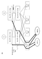
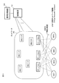
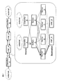
- FIG. 1 is a system configuration diagram showing an example of a network implementing an embodiment of the present invention.
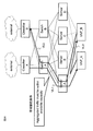
- FIG. 2 is a schematic network diagram showing an example of a service chain in the network system according to the embodiment of the present invention.
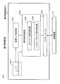
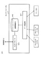
- FIG. 3 is a block diagram showing a schematic configuration of the control device according to the first embodiment of the present invention.
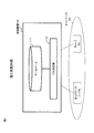
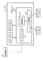
- FIG. 4 is a block diagram showing a schematic configuration of the server in the first embodiment.
- FIG. 5 is a diagram illustrating a data configuration example of a database provided in the control device according to the first embodiment.
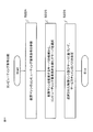
- FIG. 6 is a flowchart showing a schematic operation of the control device according to the first embodiment.
- FIG. 7 is a block diagram showing a schematic configuration of a control device according to the second embodiment of the present invention.
- FIG. 1 is a system configuration diagram showing an example of a network implementing an embodiment of the present invention.
- FIG. 2 is a schematic network diagram showing an example of a service chain in the network system according to the embodiment of the present invention
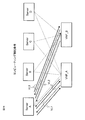
- FIG. 8 is a schematic network configuration diagram showing a virtual link for explaining the operation of the control device according to the second embodiment.
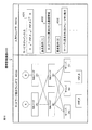
- FIG. 9 is a flowchart showing the network path determination operation of the control device according to the second embodiment.
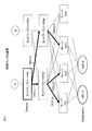
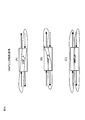
- FIG. 10 is a schematic network configuration diagram for explaining the physical link selection operation in FIG.
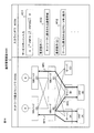
- FIG. 11 is a flowchart showing a server selection operation and a service chain path determination operation of the control device according to the second embodiment.
- FIG. 12 is a schematic network configuration diagram for explaining the server selection operation and the service chain path determination operation in FIG.
- FIG. 13 is a system configuration diagram showing another example of a network implementing the embodiment of the present invention.
- FIG. 14 is a block diagram showing a schematic configuration of an operation management apparatus according to the third embodiment of the present invention.
- FIG. 14 is a block diagram showing a schematic configuration of an operation management apparatus according to the third embodiment of the present invention.
- FIG. 15 is a diagram schematically showing a display screen which is an example of network visualization by the operation management apparatus in the third embodiment.
- FIG. 16 is a diagram schematically showing a display screen which is an example of service chain visualization by the operation management apparatus in the third embodiment.
- FIG. 17 is a block diagram showing a schematic configuration of an operation management apparatus according to the fourth embodiment of the present invention.
- FIG. 18 is a block diagram showing a schematic configuration of a control device according to the fifth embodiment of the present invention.
- FIG. 19 is a block diagram showing a schematic configuration of a network node in the fifth embodiment.
- FIG. 20 is a block diagram showing a schematic configuration of a server in the fifth embodiment.
- FIG. 21 is a schematic system configuration diagram for explaining the open flow technique employed in the fifth embodiment.
- FIG. 22 is a format diagram schematically showing the configuration of entries stored in the flow table in FIG.
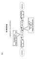
- FIG. 23 is a diagram showing a network function forwarding graph for explaining a virtual network function arrangement determining method according to the sixth embodiment of the present invention.
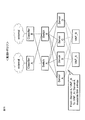
- FIG. 24 is a network diagram showing an underlay network topology in the sixth embodiment.
- FIG. 25 is a network diagram showing an extended network topology in the sixth embodiment.
- FIG. 26 is a network diagram showing a VNF arrangement of a service chain using the extended network topology in the sixth embodiment.
- FIG. 27 is a schematic network diagram for explaining a flow conservation rule when determining the VNF arrangement in FIG.
- FIG. 28 is a schematic network diagram for explaining the band constraint condition at the time of determining the VNF arrangement in FIG.
- FIG. 29 is a schematic network diagram for explaining a computing constraint condition at the time of determining the VNF arrangement in FIG.
- FIG. 30 is a schematic network diagram for explaining the VNF link constraint conditions at the time of determining the
- VNF virtual network function
- the control device 10 controls the network 20 and collectively executes VNF placement and network path setting, which will be described later.
- the network 20 includes a plurality of NW (network) nodes and a plurality of servers SV1 to SVn, which are connected to adjacent nodes or servers by physical links.
- NW network
- the control device 10 may be provided in a network operation management device.
- Each server can construct a virtual machine (VM) that executes in each of a plurality of virtual network functions VNF1 to VNFn.
- VM virtual machine
- each VNF can be arranged in the servers SV1 to SVm.
- the broken lines connecting the servers SV and the VNFs represent the possibility of VNF arrangement, and the set of these interconnections is “possible arrangement of VNFs”.
- the server and the virtual machine VM arranged there are components of the network topology, and information necessary for determining whether or not the virtual machine can be arranged (server free capacity and computing capacity) , Virtual machine requirements, etc.) to each component.
- the interconnection shown in “A possible arrangement of VNF” can be considered as an extension of the topology of the network 20.
- this extended network topology it is possible to execute the placement of VNFs on a server and the setting of a network path in a batch.
- FIG. 1 a case where a virtual link between the NW node A of the network 20 and the virtual network function VNF1 is to be mapped to the under layer is considered as an example.
- possible paths network resource information
- interconnections between each server SV and VNF1 computing resource information for VNF1 placement on each server
- the network path P between the NW node A and the server SV2 and the server SV2 as the placement destination of VNF1 are illustrated as the optimal solutions.
- another network path and / or another server that best meets the requirements of the virtual link and the VNF 1 can be the optimal solution.
- the above-described procedure may be sequentially applied by dividing the communication path. For example, the above-described procedure is applied from one NW node to the first VNF, sequentially applied from the first VNF to the next VNF, and then the next VNF, and from the last VNF to the other VNF. Applies between NW nodes.
- each of the network nodes N2 and N4 is connected to the servers SV1 to SV4 by physical links.
- Each server can arrange two virtual network functions VNF_A and VNF_B.
- the network nodes N1 to N4 and the servers SV1 to SV4 set the above-described virtual link under the control of the control device 10 (not shown).
- any one of the nodes N1 to N4 is abbreviated as “node N”
- any one of the servers SV1 to SV4 is abbreviated as “server SV” as appropriate.
- the service chain Psc shown in FIG. 2 includes a virtual link from the network node N1 to the virtual network function VNF_A through the network node N2 and the server SV1, and a virtual link from VNF_A to the VNF_B through the server V1, as indicated by a thick line. And a virtual link from VNF_B to the network node N3 through the server SV1 and the network N2.
- VNF_A and VNF_B are arranged in the server SV1.
- the network path is defined as a set of physical links constituting a virtual link corresponding to the service chain Psc. That is, in FIG. 2, a set of physical paths passing through network node N1-network node N2-server SV1 and server SV1-network node N2-network node N3 is a network path.
- the control device 10 includes a database 111 and a path determination unit 112, and includes nodes N1 to N4 and servers SV1 to SV4 of the network 20. To control.
- the path determination unit 112 collectively executes placement of VNFs on the server and network path setting corresponding to the service chain.
- the database 111 has information for the path determination unit 112 to execute the above operation.
- the control device 10 has a function of collecting the information described later from nodes, servers, and the like in the network 20 and constructing the database 111.
- each server SV can set a plurality of virtual machines VM1, VM2,... That respectively execute a plurality of VNFs.
- VNF_A and VNF_B are arranged in two virtual machines VM1 and VM2. Shall be able to. Operations as the virtual machine VM and the server are controlled by the control unit 113.
- the information stored in the database 111 includes information on network topology components (links, switches, etc.) and parameters on network topology components.
- the parameter is used by the path determination unit 112 to execute network path setting corresponding to the service chain.
- the database 111 holds information about a computing resource (information about a server and a virtual machine) in addition to information about a network (information about a link and a switch) as a component of the network topology.
- a computing resource information about a server and a virtual machine
- the network topology is expanded by expressing the server and the virtual machine VM that executes the VNF arranged there as a component of the network topology, and parameters necessary for determining the placement of the virtual machine VM By associating (CPU usage rate, VM requirement conditions, etc.) with the constituent elements, it is possible to execute the placement of the virtual machine VM and the network path setting all at once.
- the path determination unit 112 of the control device 10 refers to the first request condition regarding the network and the second request condition regarding the computing resource (operation S211).
- the “first requirement condition” is a requirement condition for the network constituting the service chain, and is, for example, a required communication band.
- the “second requirement condition” is a requirement condition for a computing resource serving as an execution base of the virtual machine VM (VNF), and is, for example, a CPU / memory resource required for the server.
- VNF virtual machine VM
- the path determination unit 112 refers to the database 111 and refers to the first parameter related to the network and the second parameter related to the computing resource (operation S212).
- the “first parameter” is a parameter associated with an entity that essentially constitutes a network, such as a link or a switch, among the components of the network topology, and specifically, a usable communication band.
- the “second parameter” is a parameter inherently associated with an entity related to computing, such as a server or a virtual machine, among the components of the network topology. Specifically, the CPU usage rate and the required CPU Such as ability.
- the path determination unit 112 based on the first parameter and the second parameter described above, the service chain path (VM of the VM) that satisfies the first request condition and the second request condition described above. (Including arrangement) is determined (operation S213).
- Both the path setting and the placement of the virtual network function (VNF) on the network can be determined at a time so as to satisfy the requirements. Thereby, an optimal VNF arrangement in consideration of the communication characteristics and communication performance of the underlay network is possible.
- a control device 10 according to a second embodiment of the present invention determines a path of a service chain on a network that satisfies a request based on a comparison result regarding a network condition and a comparison result regarding a computing condition.
- the second embodiment will be described in detail with reference to FIGS.
- the control device 10 has a database 111 and a path determination unit 122, and further receives information from network nodes and the like as in the first embodiment. It has a function of collecting and constructing the database 111.
- the database 111 is the same as that of the first embodiment, and stores information for the path determination unit 122 to execute a path determination operation as shown in FIG. Note that.
- the server SV has the configuration shown in FIG. 4 as in the first embodiment.
- the path determination unit 122 includes a network condition comparison unit 122a and a computing condition comparison unit 122b.
- the network condition comparison unit 122a compares the request condition related to the network (“first request condition” in the first embodiment) with the parameters of the constituent elements related to the network, and searches for a path satisfying the request condition.
- the computing condition comparison unit 122b compares the computing requirement condition (the “second requirement condition” in the first embodiment) with the parameters of the computing element (server), and the component ( Search for the VM location).
- the path determination unit 122 of the control device 10 includes a processor (CPU: Central : Processing) Unit) that executes a path determination control program described below, a ROM (Read Only Memory) that holds the program, and a RAM (Random that holds information). It can also be realized by a storage device such as Access Memory.
- a processor CPU: Central : Processing
- ROM Read Only Memory
- RAM Random that holds information
- the path determination unit 122 when creating a service chain, the path determination unit 122 first sets a virtual link that defines only a start point (Source) and an end point (Destination) together with a request condition. That is, a virtual link VL having the network node N1 as a start point and the virtual network function VNF_A as an end point is set, and a physical link actually passing between the start point and the end point is set as Don't Care.
- the virtual link VL may be set by a network administrator or the control device itself.
- the network condition comparison unit 122a refers to the virtual link VL described above as a service chain path setting target (operation S221), and selects a physical link candidate for configuring the virtual link VL (operation). S222). Subsequently, the network condition comparison unit 122a selects a physical link satisfying the network request condition (required communication bandwidth, etc.) from the physical link candidates (operation S223).
- a possible physical link (solid line) from the start node N1 to the end VNF_A is selected as a physical link candidate (operation S222).
- a physical link that satisfies the network request conditions is selected from the physical link candidates (operation S223).
- the physical links PHYL1 and PHYL2 / PHYL3, or PHYL4 and PHYL5 represented by thick arrows are those that satisfy the requirements among the possible communication paths from the start node N1 to the end VNF_A, Are selected as physical links for constituting the virtual link VL.
- the server SV and VNF are represented by a broken line instead of a solid line, but this is because there is actually no physical link between the server SV and VNF, and as described above, the arrangement and path setting of the VNF It means that it is a link for convenience used for calculating together.
- parameters related to communication such as a communication band are associated with the physical link indicated by the solid line or the thick arrow shown in FIG. 10, and the CPU usage rate is required for the VNF or the server SV.
- Parameters relating to computing such as CPU / memory capability are associated with each other.
- the computing condition comparison unit 122b refers to the parameter and the computing request condition for the virtual machine VM that executes VNF (operation S224). Subsequently, the computing condition comparison unit 122b compares the parameter and the computing request condition, and selects a server SV that satisfies the computing request condition from server candidates that are all server SVs on which the virtual machine is placed (operation). S225). Based on the server SV that satisfies the computing requirement selected in this way and the physical link (thick line arrow in FIG. 10) selected by the network condition comparison described above, the path of the service chain (including the placement of the VM) on the network. ) Is determined (operation S226).
- ⁇ Computing condition comparison (2)> a brute force method is adopted in which a server satisfying a condition is selected from all server candidates capable of placing VNF_A independently of the network condition comparison operation. It is not limited to.
- the server SV connected to the physical link (thick arrow in FIG. 10) selected by the network condition comparison described above is limited as a server candidate, and the server SV satisfying the computing request condition is selected from the limited server candidates. May be.
- This method has an advantage that the number of servers for confirming the computing request condition is reduced by using the network condition comparison result as compared with the brute force method.
- an optimal VNF arrangement considering the communication characteristics and communication performance of the underlay network is possible. That is, by performing a comparison between network parameters and network requirements and a comparison between computing parameters and computing conditions, both the placement of the virtual network function (VNF) and the network path setting are performed. That is, the placement of the virtual network function (VNF) on the network can be determined at a time. Furthermore, according to the second embodiment, it is possible to reduce the calculation load for computing condition comparison by using the result of network condition comparison.
- the operation management apparatus 30 can display various settings for the control apparatus 10 and the determined communication path of the service chain. . Since other configurations and functions are the same as those in the first embodiment or the second embodiment described above, the same reference numerals as those in FIG.
- the control device 10 may be provided in the operation management device 30.
- the operation management device 30 includes a virtual link setting unit 301, a request condition setting unit 302, an interface 303, and a user interface 304.
- a control unit and a storage unit are provided.
- the user interface 304 includes an information input unit such as a keyboard and an information display unit such as a monitor. The virtual link setting and request condition setting by the operation manager, the VNF arrangement on the network determined by the control device 10 and the visualization of the route, etc. Enable.
- the virtual link setting unit 301 generates a virtual link from the service chain input through the user interface 304 by the operation manager.
- the request condition setting unit 302 includes a network condition setting unit 305 and a computing condition setting unit 306, and the request conditions (network request condition and computing request condition) for configuring the service chain based on the input of the operation manager. Is generated.
- the network requirement is a network-side requirement (for example, required communication bandwidth) in the service chain
- the computing requirement is a computing resource requirement in the service chain (for example, CPU / memory capacity required).
- the operation management screen 400 displayed on the user interface 304 is divided into an input window 400a and a network display window 400b.
- the input window 400a displays a service chain input field 401 and a plurality of request condition input fields 402, and the network display window 400b displays the physical topology of the network to be managed.
- the operation management apparatus 30 acquires topology information from the database 111 of the control apparatus 10 and displays the network configuration based on the acquired topology information.
- network nodes A, B, C, and D are connected to each other by physical links, and each of the network nodes B and D is a server A, B, C. Connected by a physical link.
- each server can arrange two virtual network functions VNF_A and VNF_B.
- the operation manager inputs the following service chain in the service chain input field 401 through the user interface 304: A V VNF_A ⁇ VNF_B B B.
- the request condition setting unit 302 sets the network request condition and the computing request condition. Each is generated, transmitted to the control device 10 together with the virtual link information (VL1, VL2, VL3) and set.
- the control device 10 sets the optimum path for each of the virtual links VL1, VL2, and VL3 based on the virtual link information and the request condition information set by the operation management device 30. calculate.
- the calculation result of the optimum path is transmitted to the nodes and servers of the network 20 and the operation management apparatus 30.
- the network display window 400b of the operation management screen 400 displays the optimal paths RP1, VL1, VL2, and VL3 respectively corresponding to the virtual links VL1, VL2, and VL3.
- RP2 and RP3 are displayed.
- the network path constituting the virtual link VL1 is NW node (A) -NW node (B) -server (A)
- the network path constituting the virtual link VL2 is server (A) -NW node (B)- Server (B)
- the network path constituting the virtual link VL3 is server (B) -NW node (D) -NW node (C)
- the placement destination of the virtual network function VNF_A is server A
- the placement destination of the virtual network function VNF_B is Server B.
- the virtual link setting unit 301 and the request condition setting unit 302 of the operation management apparatus 30 are a processor (CPU: Central Processing Unit) that executes the operation management program as described above and a ROM (Read Only Memory) that stores the program. It can also be realized by a storage device such as a RAM (Random Access Memory) that holds information.
- processor Central Processing Unit
- ROM Read Only Memory
- RAM Random Access Memory
- the operation management apparatus 30 can make various settings for the control apparatus 10, and the service chain and the request set by the operation manager. Based on the conditions, as in the first and second embodiments, an optimal VNF arrangement in consideration of the communication characteristics and communication performance of the underlay network is possible.
- the operation manager can visually confirm the VNF arrangement on the network calculated by the control device 10 through the user interface, and the network operation management becomes easy. is there.
- an operation management apparatus 31 according to a fourth embodiment of the present invention has a configuration in which a path control unit 311 is provided in addition to the configuration of the operation management apparatus 30 according to the third embodiment. Therefore, the same blocks as those of the operation management apparatus 30 are denoted by the same reference numerals and description thereof is omitted.
- the path control unit 311 uses the virtual link information and the request condition information set by the virtual link setting unit 301 and the request condition setting unit 302, as described above, and the communication characteristics and communication performance of the underlay network.
- the calculation of the optimal VNF arrangement considering the above (determining the path of the control device 10) is performed.
- the calculation result of the optimum path is transmitted to the control device 11 through the interface 303 and transferred to the user interface 304. Therefore, the operation management apparatus 31 according to the present embodiment displays the optimum path on the network display window 400b of the operation management screen 400 as in the third embodiment (see FIG. 16). Since the path determination is performed by the path control unit 311, the path determination units 112 and 122 of the control device 10 in the first to third embodiments are not required for the control device 11 in the present embodiment.
- the operation management apparatus 31 according to the fourth embodiment of the present invention has the same effect as the operation management apparatus 30 according to the third embodiment described above. Further, since the operation management apparatus 31 internally calculates the optimum VNF arrangement on the network, the operation manager monitors the physical links and VNF arrangement constituting the service chain before being transferred to the control apparatus 11. The reliability of network operation management can be improved. Further, since the control device 11 does not require a path determination operation, the configuration can be simplified and the power consumption can be reduced.
- a control device determines a service chain path in a network according to each of the above-described embodiments, and connects a network node and a server so that a communication flow is transferred along the path. Control.
- the fifth embodiment will be described in detail with reference to FIGS.
- the control device 12 includes a database 111, a path determination unit 112, and a control unit 131, and is similar to the first embodiment. It has a function of collecting information from network nodes and constructing the database 111.
- the database 111 is the same as that in the first embodiment, and stores information for the path determination unit 112 to execute a path determination operation as shown in FIG. Instead of the path determination unit 112, the path determination unit 122 in the second embodiment can also be used.
- the control unit 131 is functionally provided with a network control unit 132 that controls the nodes of the network 20 and a VM control unit 133 that controls data transfer between virtual machines (VMs) in the server.
- the control unit 131 controls the network node N and the server SV so that the communication flow is transferred along the path determined by the path determination unit 112.
- the network node N in the fifth embodiment includes a data transfer unit 501, a path information database 502, and an interface 503 for communicating with the control device 12.
- the network node N receives data including a condition for identifying a flow belonging to the service chain and a transfer destination of the packet of the flow from the control device 12, and stores the data in the route information database 502.
- the data transfer unit 501 identifies a packet of a flow belonging to the service chain according to the conditions and transfer destination information stored in the route information database 502, and transfers the packet to a corresponding transfer destination (node or server).
- the server SV in the fifth embodiment switches a communication flow between a plurality of virtual machines VM for executing a plurality of VNFs and a plurality of virtual machines VM and adjacent network nodes. And a virtual switch 600 to perform.
- the virtual switch 600 can be regarded as one network node of the network topology in the present embodiment, and includes a data transfer unit 601, a path information database 602, and an interface 603 for communicating with the control device 12.
- the virtual switch 600 receives data including a condition for identifying a flow belonging to the service chain and a packet transfer destination of the flow from the control device 12 and stores the data in the route information database 602.
- the data transfer unit 601 identifies whether the packet received from the adjacent network server N or one virtual machine VM is a flow belonging to the service chain according to the conditions and transfer destination information stored in the path information database 602. , Transfer to the corresponding transfer destination (virtual machine VM or network server N). Therefore, if a packet is transferred between virtual machines VM in one server SV, a service chain can be configured without transferring it to an external network node.
- control device 12 the network node N, and the server SV, as already described, have a processor (CPU: Central Processing Unit) that executes a program for controlling each operation, a ROM (Read Only Memory) that holds a program, It can also be realized by a storage device such as a RAM (Random Access Memory) that holds information.
- processor Central Processing Unit
- ROM Read Only Memory
- RAM Random Access Memory
- a centralized control type network architecture system in which the control device 12 sets information including a condition for identifying a flow belonging to a service chain and a transfer destination of a packet of the flow is, for example, an open flow (OpenFlow).
- OpenFlow open flow
- I2RS Interface-to-the-Routing System
- ForCES Forwarding-and-Control-Element-Separation
- Open flow recognizes communication as an end-to-end flow, and performs path control, failure recovery, load balancing, etc. in units of flow.
- the flow is a series of communication packet groups having a predetermined attribute, for example, and in this embodiment refers to a flow belonging to a set service chain.
- OpenFlow will be described using the network shown in FIG. 21 as an example.
- OpenFlow switches 701, 702, and 703 are network switches adopting the OpenFlow technology, and correspond to the network node N or the virtual switch 600 of the server SV in this embodiment.
- An OpenFlow controller (OpenFlow / Controller) 704 is an information processing apparatus that controls the OpenFlow switches 701, 702, and 703, and corresponds to the control apparatus 12 in this embodiment.
- a secure channel (Secure Channel) 705 is set between each OpenFlow switch 701, 702, and 703 and the OpenFlow controller 704, and communicates with the OpenFlow controller 704 through the secure channel 705.
- the OpenFlow controller 704 sets the flow table (Flow Table) 706 of the OpenFlow switches 701, 702, and 703 via the secure channel 705.
- the secure channel 705 is a communication path between each OpenFlow switch 701, 702, 703 and the controller 704, and has been treated to prevent eavesdropping or tampering with the communication.
- FIG. 22 shows a configuration example of each entry (flow entry) in the flow table 706 provided in each open flow switch 701, 702, 703.
- the flow entry includes match fields (Match Fields) that define a matching rule for matching with information (for example, destination IP address, VLAN ID, etc.) included in the header of the packet received by the switch, and statistical information for each packet flow.
- Match Fields Field (Counters), and an action field (Action) that defines how to process a packet that matches the matching rule.
- Open flow switches 701, 702, and 703 refer to the flow table 706 when receiving the packet.
- the open flow switches 701, 702, and 703 search for a flow entry that matches the header information of the received packet.
- the OpenFlow switches 701, 702, and 703 process the received packet according to the processing method defined in the action field of the found entry.
- the processing method is defined, for example, as “forwarding a received packet from a predetermined port”, “discarding the received packet”, or “rewriting part of the header of the received packet and transferring to a predetermined port”. Has been.
- the OpenFlow switches 701, 702, and 703 transfer the received packet to the OpenFlow controller 704 through the secure channel 705, for example, to the OpenFlow controller 704. Requests the setting of a flow entry that defines how to process received packets.
- Open flow controller 704 determines the processing method of the received packet, and sets a flow entry including the determined processing method in flow table 706. After that, the open flow switches 701, 702, and 703 process subsequent packets belonging to the same flow as the received packet according to the set flow entry.
- a network node is determined so that a service chain path is determined and a communication flow is transferred along the path, as in the first to fourth embodiments.
- the server is controlled, an optimal VNF arrangement considering the communication characteristics and communication performance of the underlay network is possible.
- the network topology is extended to include a required VNF and a server capable of arranging the VNF, and a virtual machine (VNF) on the network is expanded based on the extended topology. Determine optimal placement.
- the optimum solution of this VNF arrangement can be obtained using, for example, integer programming.
- FIG. 23 consider a forwarding graph showing a service chain in which virtual network functions VNF_A and VNF_B are combined between classifiers A and B. Necessary CPU capacity and memory size (computing requirement) are set for the VNF to be combined, and a start point and an end point and necessary bandwidth (network requirement) are set for the virtual link.
- This forwarding graph corresponds to the input contents of the service chain input field 401 and the request condition field 402 in FIG. 15 described above.
- FIG. 24 shows an underlay network topology for configuring a virtual link of the forwarding graph.
- the classifier and the switch and the switch and the server are interconnected by physical links, and each physical link has an available bandwidth (network parameter).
- Each server has an available CPU and memory size (computing parameter).
- FIG. 25 shows an extended topology obtained by adding a possible arrangement of VNF_A and VNF_B to the above underlay network topology.
- a broken line that interconnects the server and the VNF indicates that the server is an arrangement destination of the VNF.
- the arrangement of service chains is determined by integer programming.
- FIG. 26 illustrates an optimal solution when VNF_A and VNF_B are arranged in the server A.
- classifier A V VNF_A ⁇ VNF_B ⁇ ⁇ classifier B
- VNF computing requirements required_cpu x (x: vnf_id) -Virtual link (VL) network requirements: required_bw x (x: vl_id) ⁇ Network path (underlay path): Upath x ij ⁇ ⁇ 0,1 ⁇ (x: vl_id, i, j: underlay_node_id)
- VL Virtual link
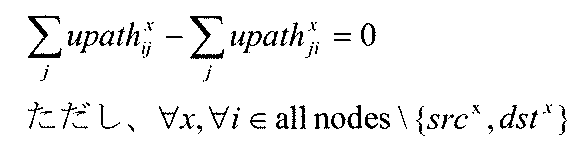
- the flow conservation law is a condition for establishing a virtual link as a path, and must be satisfied when each virtual link is mapped to an underlay.
- the difference between the transmission amount and the reception amount of the nodes other than the start point (source) and the end point (destination) must be zero.
- src x is the start point of virtual link VL (here, classifier A), and “dst x ” is the end point of virtual link VL (here, VNF_A).
- the bandwidth constraint condition is a condition for accommodating the requested bandwidth.
- the total traffic amount passing through the link ij is Must be able to accommodate available bandwidth. Therefore, it is necessary to satisfy the following formula.
- virtual links VL1 and VL3 are mapped to the physical link between the switch A and the server A. Therefore, the sum of the requested bandwidth of the virtual link VL1 and the requested bandwidth of the virtual link VL3 needs to be less than or equal to the available bandwidth of the physical link.
- a computing constraint condition is a condition for accommodating computing resources (CPU, memory capacity, etc.) required by a virtual machine (VM), and a virtual machine (VM that uses a certain server) ) Request resources must be able to be accommodated in the available resources of the server. In consideration of duplication as shown in FIG. 29, it is necessary to satisfy the following equation.
- VNF link constraint condition is a condition for determining the placement destination of the virtual machine (VM) that executes VNF. As described below, the link between the virtual machine (VM) and the server is You should use only one. As shown in FIG. 30, VNF_A will be described as an example.
- This optimal solution becomes the optimal solution in the extended topology including both the network path and the VNF arrangement, and the service chaining arrangement considering both computing and networking resources can be achieved. Further, by using integer programming, it is possible to quickly obtain the VNF arrangement on the network.
- the present invention can be used in a system in which a virtual network function (VNF) is arranged on a network.
- VNF virtual network function
Landscapes
- Engineering & Computer Science (AREA)
- Computer Networks & Wireless Communication (AREA)
- Signal Processing (AREA)
- Environmental & Geological Engineering (AREA)
- Computing Systems (AREA)
- Theoretical Computer Science (AREA)
- Human Computer Interaction (AREA)
- Data Exchanges In Wide-Area Networks (AREA)
Abstract
Description
本発明によるネットワーク制御方法は、複数のノードおよびサーバを有するネットワークを制御する方法であって、前記ネットワークのリンクおよびノードに関する第1情報と、仮想ネットワーク機能を配置可能なサーバのコンピューティングリソースに関する第2情報と、を格納手段に格納し、少なくとも一つの仮想ネットワーク機能が要求された場合、前記第1情報および前記第2情報に基づいて、前記要求された仮想ネットワーク機能のサーバへの配置と、配置先のサーバに接続する前記ネットワークのパス設定と、を一括で実行する、ことを特徴とする。
本発明によるネットワークシステムは、複数のノードおよびサーバを有するネットワークと前記ネットワークを制御する制御装置とを有するネットワークシステムであって、前記制御装置が、ネットワークのリンクおよびノードに関する第1情報と、少なくとも1つの仮想ネットワーク機能を配置可能なサーバのコンピューティングリソースに関する第2情報と、を格納する格納手段と、少なくとも一つの仮想ネットワーク機能が要求された場合、前記第1情報および前記第2情報に基づいて、前記要求された仮想ネットワーク機能のサーバへの配置と、配置先のサーバに接続する前記ネットワークのパス設定と、を一括で実行するパス決定手段と、を有することを特徴とする。
本発明の実施形態によれば、仮想ネットワーク機能(VNF)の配置とネットワークのパス設定とを一括で実行することにより、アンダーレイネットワークの通信特性および通信性能を考慮した最適なVNF配置を実現できる。以下、図1に示すネットワークシステムを参照しながら本発明の実施形態の概要を説明する。
以下、説明を簡略化するために、図2に示すネットワーク構成を参照しながら、本発明の実施形態におけるサービスチェインについて説明する。
1.1)システム構成
図3において、本発明の第1実施形態による制御装置10は、データベース111およびパス決定部112を有し、ネットワーク20のノードN1~N4およびサーバSV1~SV4を制御する。パス決定部112はVNFのサーバへの配置とサービスチェインに対応するネットワークのパス設定とを一括で実行する。データベース111は、後述するように(図5参照)、パス決定部112が上記動作を実行するための情報を有する。なお、図示されていないが、制御装置10は、ネットワーク20内のノード、サーバ等から後述する情報を収集してデータベース111を構築する機能を有する。
図6に示すように、制御装置10のパス決定部112は、ネットワークに関する第一の要求条件とコンピューティングリソースに関する第二の要求条件とを参照する(動作S211)。ここで、「第一の要求条件」は、サービスチェインを構成するネットワークに対する要求条件であり、例えば、要求される通信帯域等である。「第二の要求条件」は、仮想マシンVM(VNF)の実行基盤となるコンピューティングリソースに対する要求条件であり、例えばサーバに要求されるCPU/メモリリソース等である。
上述したように、本発明の第1実施形態によれば、ネットワークに関する第一のパラメータとコンピューティングに関する第二のパラメータとに基づいて、仮想ネットワーク機能(VNF)の配置とネットワークのパス設定との両方を、すなわちネットワーク上の仮想ネットワーク機能(VNF)の配置を、要求条件を満たすように一度で決定することができる。これにより、アンダーレイネットワークの通信特性および通信性能を考慮した最適なVNF配置が可能となる。
本発明の第2実施形態による制御装置10は、ネットワーク条件に関する比較結果とコンピューティング条件に関する比較結果とに基づいて、要求を満たすネットワーク上でのサービスチェインのパスを決定する。以下、図7~図12を参照しながら第2実施形態について詳述する。
図7において、本発明の第2実施形態による制御装置10はデータベース111およびパス決定部122を有し、さらに、第1実施形態と同様に、ネットワークのノード等から情報を収集してデータベース111を構築する機能を有する。データベース111は、第1実施形態と同様であり、図5に示すように、パス決定部122がパス決定動作を実行するための情報を格納する。なお。サーバSVについては、第1実施形態と同様に、図4に示す構成を有する。
以下、ネットワーク条件比較部122aおよびコンピューティング条件比較部122bを含むパス決定部122のパス決定動作について説明する。
図9において、ネットワーク条件比較部122aは、上述した仮想リンクVLをサービスチェインのパス設定の対象として参照し(動作S221)、この仮想リンクVLを構成するための物理リンクの候補を選択する(動作S222)。続いて、ネットワーク条件比較部122aは、物理リンクの候補からネットワーク要求条件(要求される通信帯域等)を満たす物理リンクを選択する(動作S223)。
図11において、コンピューティング条件比較部122bは、VNFを実行する仮想マシンVMに対するパラメータおよびコンピューティング要求条件を参照する(動作S224)。続いて、コンピューティング条件比較部122bは、パラメータとコンピューティング要求条件とを比較し、当該仮想マシンを配置する全てのサーバSVであるサーバ候補からコンピューティング要求条件を満たすサーバSVを選択する(動作S225)。こうして選択されたコンピューティング要求条件を満たすサーバSVと上述したネットワーク条件比較により選択された物理リンク(図10の太線矢印)とに基づいて、ネットワーク上でのサービスチェインのパス(VMの配置を含む)を決定する(動作S226)。
上述したコンピューティング条件比較(1)では、上記ネットワーク条件比較動作とは独立してVNF_Aを配置可能な全てのサーバ候補の中から条件を満たすサーバを選択するという総当たり方式を採用したが、これに限定されるものではない。たとえば、上述したネットワーク条件比較により選択された物理リンク(図10の太線矢印)に接続したサーバSVをサーバ候補として限定しておき、限定されたサーバ候補からコンピューティング要求条件を満たすサーバSVを選択してもよい。この方式は、ネットワーク条件比較結果を利用することにより、総当たり方式の場合よりもコンピューティング要求条件を確認するサーバ数が減少するという利点がある。
上述したように、本発明の第2実施形態においても、第1実施形態と同様に、アンダーレイネットワークの通信特性および通信性能を考慮した最適なVNF配置が可能となる。すなわち、ネットワークに関するパラメータとネットワーク要求条件との比較と、コンピューティングに関するパラメータとコンピューティング条件との比較とを実行することで、仮想ネットワーク機能(VNF)の配置とネットワークのパス設定との両方を、すなわちネットワーク上の仮想ネットワーク機能(VNF)の配置を、一度で決定することができる。さらに、第2実施形態によれば、ネットワーク条件比較の結果を利用することで、コンピューティング条件比較の計算負荷を軽減することも可能となる。
図13に示すように、本発明の第3実施形態によるネットワークシステムでは、運用管理装置30が制御装置10に対する各種設定および決定されたサービスチェインの通信経路の表示を行うことができる。その他の構成および機能は上述した第1実施形態あるいは第2実施形態と同様であるから、図1と同じ参照番号を使用して説明は省略する。なお、制御装置10は運用管理装置30内に設けられてもよい。
図14において、運用管理装置30は、仮想リンク設定部301、要求条件設定部302、インターフェース303、およびユーザインターフェース304を有し、その他、図示しない制御部や記憶部を有する。ユーザインターフェース304はキーボード等の情報入力部とモニタ等の情報表示部とを含み、運用管理者による仮想リンク設定および要求条件設定、制御装置10により決定されたネットワーク上のVNF配置および経路の可視化などを可能にする。
図15に例示するように、ユーザインターフェース304に表示された運用管理画面400は、入力ウィンドウ400aとネットワーク表示ウィンドウ400bとに分割されている。入力ウィンドウ400aにはサービスチェイン入力欄401と複数の要求条件入力欄402とが表示され、ネットワーク表示ウィンドウ400bには運用管理対象であるネットワークの物理的なトポロジが表示される。たとえば、運用管理装置30は、制御装置10のデータベース111からトポロジ情報を取得し、取得したトポロジ情報に基づいてネットワークの構成を表示する。
A ⇔ VNF_A ⇔ VNF_B ⇔ B。
VL1:始点=NWノード(A);終点=VNF_A
VL2:始点=VNF_A ;終点=VNF_B
VL3:始点=VNF_B ;終点=NWノード(C)
上述したように、本発明の第3実施形態によれば、運用管理装置30が制御装置10に対して各種設定を行うことができ、運用管理者が設定したサービスチェインおよび要求条件に基づいて、第1および第2実施形態と同様に、アンダーレイネットワークの通信特性および通信性能を考慮した最適なVNF配置が可能となる。
図17に示すように、本発明の第4実施形態による運用管理装置31は、第3実施形態による運用管理装置30の構成に加えてパス制御部311を設けた構成を有する。したがって、運用管理装置30と同様のブロックには同じ参照番号を付して説明は省略する。
本発明の第5実施形態による制御装置は、上述した各実施形態によりネットワークにおけるサービスチェインのパスを決定し、当該パスに沿って通信フローが転送されるようにネットワークノードおよびサーバを制御する。以下、図18~図22を参照しながら第5実施形態について詳述する。
図18に示すように、本発明の第5実施形態による制御装置12は、データベース111、パス決定部112および制御部131を有し、さらに、第1実施形態と同様に、ネットワークのノード等から情報を収集してデータベース111を構築する機能を有する。データベース111は、第1実施形態と同様であり、図5に示すように、パス決定部112がパス決定動作を実行するための情報を格納する。なお、パス決定部112の代わりに、第2実施形態におけるパス決定部122を用いることもできる。制御部131には、ネットワーク20のノードを制御するネットワーク制御部132とサーバ内の仮想マシン(VM)間のデータ転送を制御するVM制御部133とが機能的に設けられている。制御部131は、パス決定部112により決定されたパスに沿って通信フローが転送されるようにネットワークノードNおよびサーバSVを制御する。
オープンフローは、通信をエンドツーエンドのフローとして認識し、フロー単位で経路制御、障害回復、負荷分散等を実行する。ここで、フローとは、例えば所定の属性を有する一連の通信パケット群のことであり、本実施形態においては設定されたサービスチェインに属するフローをいう。以下、図21に示すネットワークを一例としてオープンフローについて説明する。
本発明の第5実施形態によれば、第1~第4実施形態と同様にサービスチェインのパスを決定し、当該パスに沿って通信フローが転送されるようにネットワークのノードあるいはサーバを制御するので、アンダーレイネットワークの通信特性および通信性能を考慮した最適なVNF配置が可能となる。
既に述べたように、サービスチェイニングでは、単に仮想マシンの配置を考慮するだけでは不十分であり、コンピューティングおよびネットワーキングの両方のリソースを考慮することが必要である。本発明の第6実施形態によれば、必要とされるVNFとそれを配置可能なサーバとを含むようにネットワークトポロジを拡張し、この拡張トポロジに基づいてネットワーク上での仮想マシン(VNF)の最適配置を決定する。このVNF配置の最適解は、たとえば整数計画法(Integer Programming)を用いて求めることができる。
VL1:始点=クラシファイアA;終点=VNF_A
VL2:始点=VNF_A ;終点=VNF_B
VL3:始点=VNF_B ;終点=クラシファイアB
以下、図26に示すようなネットワーク上での最適VNF配置を決定する整数計画法による計算過程を示す。変数の定義は次の通りである。
・VNFのコンピューティング要求条件:required_cpux (x:vnf_id)
・仮想リンク(VL)のネットワーク要求条件:required_bwx (x:vl_id)
・ネットワークパス(アンダーレイパス):
・upathx ij ∈ {0,1} (x:vl_id, i,j:underlay_node_id) ここで、仮想リンクxが物理ノードiとjとの間のリンクijを使用していれば、upathx ij=1である。
・サーバのコンピューティングパラメータ(利用可能CPU):
available_cpus (s:server_id)
・リンクのネットワークパラメータ(利用可能帯域幅):
available_bwij (i:from_id, j:to_id)
・目的関数Cの最小化/最大化によりVNF配置の最適解を計算する。目的関数Cの一例を次式に示す:

フロー保存則は仮想リンクをパスとして成立させるための条件であり、各仮想リンクがアンダーレイにマッピングされるとき満たす必要がある。以下、図27を参照しながら説明する。


帯域幅制約条件は要求帯域を収容するための条件であり、リンクijに仮想リンクVLがマッピングされている場合、当該リンクijを通る総トラフィック量が当該リンクijの使用可能な帯域幅に収容可能でなければならない。したがって、次式を満たす必要がある。

コンピューティング制約条件は、仮想マシン(VM)が要求するコンピューティングリソース(CPU、メモリ容量など)を収容するための条件であり、あるサーバを使用する仮想マシン(VM)の要求リソースの総和が当該サーバの使用可能なリソースに収容可能でなければならない。図29に示すような重複を考慮して、次式を満たす必要がある。

VNFリンク制約条件は、VNFを実行する仮想マシン(VM)の配置先を決めるための条件であり、次に述べるように、仮想マシン(VM)とサーバのリンクは一本しか使ってはならない。図30に示すように、VNF_Aを例として説明する。
upathsv x = upathsv y (∀s,∀ν,∀x|dstx=ν, ∀y|dstx=ν)
upathvs x = upathvs y (∀s,∀ν,∀x|srcx=ν, ∀y|srcx=ν)
upathsv x = upathvs y (∀s,∀ν,∀x|dstx=ν, ∀y|srcx=ν)
以上述べたように、本実施形態によれば、上記制約条件の下で線形計画法により、目的関数Cが最小となるupathx ij=1の物理リンクの集合をVNF配置の最適解として求めることができる。この最適解はネットワークパスおよびVNF配置の両方を含む拡張トポロジでの最適解となり、コンピューティングおよびネットワーキングリソースの両方を考慮したサービスチェイニング配置を達成することができる。また、整数計画法を用いることでネットワーク上でのVNF配置を迅速に得ることができる。
20 ネットワーク
30、31 運用管理装置
111 データベース
112 パス決定部
113 制御部
122 パス決定部
122a ネットワーク条件比較部
122b コンピューティング条件比較部
131 制御部
132 ネットワーク制御部
133 仮想マシン制御部
301 仮想リンク設定部
302 要求条件設定部
303 インターフェース
304 ユーザインターフェース
305 ネットワーク条件設定部
306 コンピューティング条件設定部
311 パス制御部
400 運用管理画面
400a 入力ウィンドウ
400b ネットワーク表示ウィンドウ
401 サービスチェイン入力欄
402 要求条件入力欄
501 データ転送部
502 経路情報データベース
503 インターフェース
600 仮想スイッチ
601 データ転送部
602 経路情報データベース
603 インターフェース
701、702、703 オープンフロースイッチ
704 オープンフローコントローラ
705 セキュリティチャネル
706 フローテーブル
Claims (27)
- 複数のノードおよびサーバを有するネットワークを制御する装置であって、
前記ネットワークのリンクおよびノードに関する第1情報と、仮想ネットワーク機能を配置可能なサーバのコンピューティングリソースに関する第2情報と、を格納する格納手段と、
少なくとも一つの仮想ネットワーク機能が要求された場合、前記第1情報および前記第2情報に基づいて、前記要求された仮想ネットワーク機能のサーバへの配置と、配置先のサーバに接続する前記ネットワークのパス設定と、を一括で実行するパス決定手段と、
を有することを特徴とするネットワーク制御装置。 - 前記パス決定手段は、前記第1情報および前記第2情報に基づいて、前記少なくとも一つの仮想ネットワーク機能の要求条件を満たす前記パスを決定することを特徴とする請求項1に記載のネットワーク制御装置。
- 前記パス決定手段は、
前記少なくとも一つの仮想ネットワーク機能のネットワークに関する第1要求条件と前記第1情報とを比較する第1比較手段と、
前記少なくとも一つの仮想ネットワーク機能のコンピューティングリソースに関する第2要求条件と前記第2情報とを比較する第2比較手段と、
を有し、前記第1比較手段の比較結果と前記第2比較手段の比較結果とに基づいて、前記第1要求条件および前記第2要求条件を共に満たす前記パスを決定することを特徴とする請求項1または2に記載のネットワーク制御装置。 - 前記パス決定手段は、前記第1比較手段の比較結果により前記第1要求条件を満たすネットワークパス候補を選択し、前記第2比較手段の比較結果により前記第2要求条件を満たすサーバへの配置を決定し、前記サーバへの配置に従って前記ネットワークパス候補から前記パスを決定する、ことを特徴とする請求項3に記載のネットワーク制御装置。
- 前記パス決定手段は、前記第1要求条件を満たすネットワークパス候補の選択と、前記第2要求条件を満たすサーバへの配置の決定とを独立に実行することを特徴とする請求項4に記載のネットワーク制御装置。
- 前記パス決定手段は、前記第1要求条件を満たすネットワークパス候補の中から前記第2要求条件を満たすサーバへの配置を決定することを特徴とする請求項4に記載のネットワーク制御装置。
- 前記サーバには複数の同一あるいは異なる仮想ネットワーク機能が配置可能であることを特徴とする請求項1-6のいずれか1項に記載のネットワーク制御装置。
- 前記ネットワークのノードと、前記サーバにおける前記仮想ネットワーク機能を実行する仮想マシンと、を制御する制御手段を更に有し、
前記制御手段が前記パス決定手段により決定された前記パスに沿って通信フローが転送されるように前記ネットワークのノードおよびサーバを制御する、ことを特徴とする請求項1-7のいずれか1項に記載のネットワーク制御装置。 - 前記サーバは前記ネットワークの少なくとも1つの隣接ノードと接続し、複数の同一あるいは異なる仮想ネットワーク機能の間および/または前記隣接ノードとの間でデータ転送を行う仮想スイッチを有し、前記制御手段が前記ノードと同様に前記仮想スイッチを制御することを特徴とする請求項8に記載のネットワーク制御装置。
- 複数のノードおよびサーバを有するネットワークを制御する方法であって、
前記ネットワークのリンクおよびノードに関する第1情報と、仮想ネットワーク機能を配置可能なサーバのコンピューティングリソースに関する第2情報と、を格納手段に格納し、
少なくとも一つの仮想ネットワーク機能が要求された場合、前記第1情報および前記第2情報に基づいて、前記要求された仮想ネットワーク機能のサーバへの配置と、配置先のサーバに接続する前記ネットワークのパス設定と、を一括で実行する、
ことを特徴とするネットワーク制御方法。 - 前記第1情報および前記第2情報に基づいて、前記少なくとも一つの仮想ネットワーク機能の要求条件を満たす前記パスを決定する、ことを特徴とする請求項10に記載のネットワーク制御方法。
- 第1比較手段が前記少なくとも一つの仮想ネットワーク機能のネットワークに関する第1要求条件と前記第1情報とを比較し、
第2比較手段が前記少なくとも一つの仮想ネットワーク機能のコンピューティングリソースに関する第2要求条件と前記第2情報とを比較し、
前記第1比較手段の比較結果と前記第2比較手段の比較結果とに基づいて、前記第1要求条件および前記第2要求条件を共に満たす前記パスを決定する、
ことを特徴とする請求項10または11に記載のネットワーク制御方法。 - 前記第1比較手段の比較結果により前記第1要求条件を満たすネットワークパス候補を選択し、
前記第2比較手段の比較結果により前記第2要求条件を満たすサーバへの配置を決定し、
前記サーバへの配置に従って前記ネットワークパス候補から前記パスを決定する、
ことを特徴とする請求項12に記載のネットワーク制御方法。 - 前記第1要求条件を満たすネットワークパス候補の選択と、前記第2要求条件を満たすサーバへの配置の決定とを独立に実行することを特徴とする請求項13に記載のネットワーク制御方法。
- 前記第1要求条件を満たすネットワークパス候補の中から前記第2要求条件を満たすサーバへの配置を決定することを特徴とする請求項13に記載のネットワーク制御方法。
- 前記サーバには複数の同一あるいは異なる仮想ネットワーク機能が配置可能であることを特徴とする請求項10-15のいずれか1項に記載のネットワーク制御方法。
- 決定された前記パスに沿って通信フローが転送されるように前記ネットワークのノードと、前記サーバにおける前記仮想ネットワーク機能を実行する仮想マシンとを制御する、ことを特徴とする請求項10-16のいずれか1項に記載のネットワーク制御方法。
- 前記サーバは前記ネットワークの少なくとも1つの隣接ノードと接続し、複数の同一あるいは異なる仮想ネットワーク機能の間および/または前記隣接ノードとの間でデータ転送を行う仮想スイッチを有し、
前記ノードと同様に前記仮想スイッチを制御することを特徴とする請求項17に記載のネットワーク制御方法。 - 複数のノードおよびサーバを有するネットワークと前記ネットワークを制御する制御装置とを有するネットワークシステムであって、
前記制御装置が、
ネットワークのリンクおよびノードに関する第1情報と、少なくとも1つの仮想ネットワーク機能を配置可能なサーバのコンピューティングリソースに関する第2情報と、を格納する格納手段と、
少なくとも一つの仮想ネットワーク機能が要求された場合、前記第1情報および前記第2情報に基づいて、前記要求された仮想ネットワーク機能のサーバへの配置と、配置先のサーバに接続する前記ネットワークのパス設定と、を一括で実行するパス決定手段と、
を有する、
ことを特徴とするネットワークシステム。 - 前記パス決定手段は、前記第1情報および前記第2情報に基づいて、前記少なくとも一つの仮想ネットワーク機能の要求条件を満たす前記パスを決定することを特徴とする請求項19に記載のネットワークシステム。
- 前記パス決定手段は、
前記少なくとも一つの仮想ネットワーク機能のネットワークに関する第1要求条件と前記第1情報とを比較する第1比較手段と、
前記少なくとも一つの仮想ネットワーク機能のコンピューティングリソースに関する第2要求条件と前記第2情報とを比較する第2比較手段と、
を有し、前記第1比較手段の比較結果と前記第2比較手段の比較結果とに基づいて、前記第1要求条件および前記第2要求条件を共に満たす前記パスを決定することを特徴とする請求項19または20に記載のネットワークシステム。 - 前記パス決定手段は、前記第1比較手段の比較結果により前記第1要求条件を満たすネットワークパス候補を選択し、前記第2比較手段の比較結果により前記第2要求条件を満たすサーバへの配置を決定し、前記サーバへの配置に従って前記ネットワークパス候補から前記パスを決定する、ことを特徴とする請求項21に記載のネットワークシステム。
- 前記サーバには複数の同一あるいは異なる仮想ネットワーク機能が配置可能であることを特徴とする請求項19-22のいずれか1項に記載のネットワークシステム。
- 前記制御装置の運用管理を行う運用管理装置を更に有し、
前記運用管理装置が、
前記制御装置に対して前記少なくとも一つの仮想ネットワーク機能の要求条件を設定する要求条件設定手段と、
前記ネットワークのトポロジを前記決定されたパスと共に表示する表示手段と、
を有する
ことを特徴とする請求項19-23のいずれか1項に記載のネットワークシステム。 - 前記制御装置は、前記ネットワークのノードと、前記サーバにおける前記仮想ネットワーク機能を実行する仮想マシンと、を制御する制御手段を更に有し、
前記制御手段が前記パス決定手段により決定された前記パスに沿って通信フローが転送されるように前記ネットワークのノードおよびサーバを制御する、ことを特徴とする請求項19-24のいずれか1項に記載のネットワークシステム。 - 前記サーバは前記ネットワークの少なくとも1つの隣接ノードと接続し、複数の同一あるいは異なる仮想ネットワーク機能の間および/または前記隣接ノードとの間でデータ転送を行う仮想スイッチを有し、前記制御手段が前記ノードと同様に前記仮想スイッチを制御することを特徴とする請求項25に記載のネットワークシステム。
- 複数のノードおよびサーバを有するネットワーク制御装置としてコンピュータを機能させるプログラムであって、
前記ネットワークのリンクおよびノードに関する第1情報と、仮想ネットワーク機能を配置可能なサーバのコンピューティングリソースに関する第2情報と、格納手段に格納する機能と、
パス決定手段が、少なくとも一つの仮想ネットワーク機能が要求された場合、前記第1情報および前記第2情報に基づいて、前記要求された仮想ネットワーク機能のサーバへの配置と、配置先のサーバに接続する前記ネットワークのパス設定と、を一括で実行する機能と、
を前記コンピュータに実現することを特徴とするプログラム。
Priority Applications (4)
| Application Number | Priority Date | Filing Date | Title |
|---|---|---|---|
| JP2015561226A JP6398999B2 (ja) | 2014-02-06 | 2015-02-05 | ネットワークシステム、ネットワーク制御方法および制御装置 |
| ES15746658T ES2743547T3 (es) | 2014-02-06 | 2015-02-05 | Sistema de red, método de control de red y dispositivo de control |
| EP15746658.2A EP3104560B1 (en) | 2014-02-06 | 2015-02-05 | Network system, network control method, and control device |
| US15/117,180 US10218615B2 (en) | 2014-02-06 | 2015-02-05 | Network system, network control method and control apparatus |
Applications Claiming Priority (2)
| Application Number | Priority Date | Filing Date | Title |
|---|---|---|---|
| JP2014-020979 | 2014-02-06 | ||
| JP2014020979 | 2014-02-06 |
Publications (1)
| Publication Number | Publication Date |
|---|---|
| WO2015118874A1 true WO2015118874A1 (ja) | 2015-08-13 |
Family
ID=53777686
Family Applications (1)
| Application Number | Title | Priority Date | Filing Date |
|---|---|---|---|
| PCT/JP2015/000525 Ceased WO2015118874A1 (ja) | 2014-02-06 | 2015-02-05 | ネットワークシステム、ネットワーク制御方法および制御装置 |
Country Status (5)
| Country | Link |
|---|---|
| US (1) | US10218615B2 (ja) |
| EP (1) | EP3104560B1 (ja) |
| JP (2) | JP6398999B2 (ja) |
| ES (1) | ES2743547T3 (ja) |
| WO (1) | WO2015118874A1 (ja) |
Cited By (12)
| Publication number | Priority date | Publication date | Assignee | Title |
|---|---|---|---|---|
| JP2015154325A (ja) * | 2014-02-17 | 2015-08-24 | 日本電信電話株式会社 | 装置選択ネットワークシステム、装置選択サーバおよびプログラム |
| JP2017076967A (ja) * | 2015-10-12 | 2017-04-20 | 富士通株式会社 | マルチドメイン・ネットワークにおけるバーテックス中心のサービス機能チェーン形成 |
| JP2017079352A (ja) * | 2015-10-19 | 2017-04-27 | 日本電信電話株式会社 | リソース割当管理装置、および、サービスチェイニングシステム |
| JP2017111744A (ja) * | 2015-12-18 | 2017-06-22 | 日本電信電話株式会社 | データ処理システム、データ処理方法、カスタマイズドサービス管理制御装置及びカスタマイズドサービス管理制御プログラム |
| EP3206349A1 (en) | 2016-02-15 | 2017-08-16 | Fujitsu Limited | Packet relay program and packet relay method |
| WO2018142700A1 (ja) * | 2017-02-02 | 2018-08-09 | 日本電信電話株式会社 | 制御装置、制御方法、及びプログラム |
| CN109863726A (zh) * | 2016-09-09 | 2019-06-07 | At&T知识产权一部有限合伙公司 | 分布式客户驻地装置 |
| US10652148B2 (en) | 2014-10-30 | 2020-05-12 | At&T Intellectual Property I, L. P. | Distributed customer premises equipment |
| JPWO2021048981A1 (ja) * | 2019-09-12 | 2021-03-18 | ||
| CN114598613A (zh) * | 2022-04-07 | 2022-06-07 | 中国移动通信集团陕西有限公司 | 虚拟网络功能的部署方法、装置、设备及介质 |
| CN115941678A (zh) * | 2022-09-28 | 2023-04-07 | 北京邮电大学 | 云边缘协同服务链部署方法及装置 |
| CN119011423A (zh) * | 2024-10-24 | 2024-11-22 | 北京航空航天大学 | 基于网络流量汇聚性的vnf部署方法、装置及设备 |
Families Citing this family (14)
| Publication number | Priority date | Publication date | Assignee | Title |
|---|---|---|---|---|
| US10116514B1 (en) * | 2015-03-30 | 2018-10-30 | Amdocs Development Limited | System, method and computer program for deploying an orchestration layer for a network based on network function virtualization (NFV) |
| JP6398999B2 (ja) * | 2014-02-06 | 2018-10-03 | 日本電気株式会社 | ネットワークシステム、ネットワーク制御方法および制御装置 |
| US10630557B2 (en) * | 2015-10-19 | 2020-04-21 | Nicira, Inc. | Virtual network management |
| US9438478B1 (en) * | 2015-11-13 | 2016-09-06 | International Business Machines Corporation | Using an SDN controller to automatically test cloud performance |
| US10439882B2 (en) * | 2016-11-15 | 2019-10-08 | T-Mobile Usa, Inc. | Virtualized networking application and infrastructure |
| US10469317B1 (en) * | 2017-03-29 | 2019-11-05 | Juniper Networks, Inc. | Virtualized network function descriptors for virtualized network function configuration |
| US11575579B2 (en) | 2017-04-25 | 2023-02-07 | Nutanix, Inc. | Systems and methods for networked microservice modeling |
| US10735275B2 (en) * | 2017-06-16 | 2020-08-04 | Cisco Technology, Inc. | Releasing and retaining resources for use in a NFV environment |
| US11070446B2 (en) * | 2017-10-24 | 2021-07-20 | At&T Intellectual Property I, L.P. | Intelligent network resource orchestration system and method for internet enabled device applications and services |
| US10809987B2 (en) | 2018-08-14 | 2020-10-20 | Hyperblox Inc. | Software acceleration platform for supporting decomposed, on-demand network services |
| KR102546521B1 (ko) * | 2019-01-04 | 2023-06-22 | 한국전자통신연구원 | 분산 엣지 클라우드 환경에서의 서비스 제공 방법 및 서비스 제공 장치 |
| CN111385202B (zh) * | 2020-03-17 | 2022-03-11 | 重庆邮电大学 | 一种基于虚拟网络功能的路由分配方法 |
| US20230135699A1 (en) * | 2020-06-29 | 2023-05-04 | Intel Corporation | Service function chaining services in edge data network and 5g networks |
| CN112565082B (zh) * | 2020-12-25 | 2022-06-17 | 鹏城实验室 | 基于混合网络的服务链映射方法、智能终端及存储介质 |
Citations (1)
| Publication number | Priority date | Publication date | Assignee | Title |
|---|---|---|---|---|
| US20130329734A1 (en) * | 2012-06-11 | 2013-12-12 | Radware, Ltd. | Techniques for providing value-added services in sdn-based networks |
Family Cites Families (12)
| Publication number | Priority date | Publication date | Assignee | Title |
|---|---|---|---|---|
| JP2002314587A (ja) | 2001-04-17 | 2002-10-25 | Hitachi Ltd | ルート設定方法、ルート設定サービス方法、ネットワーク経路管理システム及びネットワーク支援システム |
| US7170857B2 (en) * | 2001-08-10 | 2007-01-30 | Strix Systems, Inc. | Virtual linking using a wireless device |
| US8539098B2 (en) * | 2007-10-17 | 2013-09-17 | Dispersive Networks, Inc. | Multiplexed client server (MCS) communications and systems |
| US8676949B2 (en) | 2009-11-25 | 2014-03-18 | Citrix Systems, Inc. | Methods for interfacing with a virtualized computing service over a network using a lightweight client |
| JP5304813B2 (ja) | 2011-02-22 | 2013-10-02 | 沖電気工業株式会社 | 通信ノード装置 |
| JP5256406B2 (ja) * | 2011-03-30 | 2013-08-07 | 日本電信電話株式会社 | ネットワーク可視化方法およびネットワーク可視化装置 |
| US9112812B2 (en) * | 2011-09-22 | 2015-08-18 | Embrane, Inc. | Distributed virtual appliance |
| US9935876B2 (en) * | 2012-03-30 | 2018-04-03 | Nec Corporation | Communication system, control apparatus, communication apparatus, communication control method, and program |
| US9350481B2 (en) * | 2012-10-08 | 2016-05-24 | Futurewei Technologies, Inc. | Transport functions virtualization for wavelength division multiplexing (WDM)-based optical networks |
| US9973375B2 (en) * | 2013-04-22 | 2018-05-15 | Cisco Technology, Inc. | App store portal providing point-and-click deployment of third-party virtualized network functions |
| EP2849064B1 (en) * | 2013-09-13 | 2016-12-14 | NTT DOCOMO, Inc. | Method and apparatus for network virtualization |
| JP6398999B2 (ja) * | 2014-02-06 | 2018-10-03 | 日本電気株式会社 | ネットワークシステム、ネットワーク制御方法および制御装置 |
-
2015
- 2015-02-05 JP JP2015561226A patent/JP6398999B2/ja active Active
- 2015-02-05 ES ES15746658T patent/ES2743547T3/es active Active
- 2015-02-05 WO PCT/JP2015/000525 patent/WO2015118874A1/ja not_active Ceased
- 2015-02-05 EP EP15746658.2A patent/EP3104560B1/en active Active
- 2015-02-05 US US15/117,180 patent/US10218615B2/en active Active
-
2018
- 2018-09-05 JP JP2018165879A patent/JP6648790B2/ja active Active
Patent Citations (1)
| Publication number | Priority date | Publication date | Assignee | Title |
|---|---|---|---|---|
| US20130329734A1 (en) * | 2012-06-11 | 2013-12-12 | Radware, Ltd. | Techniques for providing value-added services in sdn-based networks |
Non-Patent Citations (3)
| Title |
|---|
| DAISUKE SASO: "Kasoka Tsushin Gijutsu no Hatten SDN/OpenFlow to NFV no Saishin Doko", SOFTWARE DESIGN, vol. 278th, 18 December 2013 (2013-12-18), pages 18 - 23, XP008184637 * |
| See also references of EP3104560A4 * |
| WOLFGANG JOHN ET AL.: "Research Directions in Network Service Chaining", SDN4FNS 2013, 2013 WORKSHOP ON SOFTWARE DEFINED NETWORKS FOR FUTURE NETWORKS AND SERVICES, November 2013 (2013-11-01), XP032540960, Retrieved from the Internet <URL:http://ieeexplore.ieee.org/xpl/articleDetails.jsp?arnumber=6702549> * |
Cited By (21)
| Publication number | Priority date | Publication date | Assignee | Title |
|---|---|---|---|---|
| JP2015154325A (ja) * | 2014-02-17 | 2015-08-24 | 日本電信電話株式会社 | 装置選択ネットワークシステム、装置選択サーバおよびプログラム |
| US10652148B2 (en) | 2014-10-30 | 2020-05-12 | At&T Intellectual Property I, L. P. | Distributed customer premises equipment |
| US11388093B2 (en) | 2014-10-30 | 2022-07-12 | Ciena Corporation | Distributed customer premises equipment |
| JP2017076967A (ja) * | 2015-10-12 | 2017-04-20 | 富士通株式会社 | マルチドメイン・ネットワークにおけるバーテックス中心のサービス機能チェーン形成 |
| JP2017079352A (ja) * | 2015-10-19 | 2017-04-27 | 日本電信電話株式会社 | リソース割当管理装置、および、サービスチェイニングシステム |
| JP2017111744A (ja) * | 2015-12-18 | 2017-06-22 | 日本電信電話株式会社 | データ処理システム、データ処理方法、カスタマイズドサービス管理制御装置及びカスタマイズドサービス管理制御プログラム |
| EP3206349A1 (en) | 2016-02-15 | 2017-08-16 | Fujitsu Limited | Packet relay program and packet relay method |
| US10171342B2 (en) | 2016-02-15 | 2019-01-01 | Fujitsu Limited | Recording medium and packet relay method for relaying a packet in a first sub-domain among a plurality of sub-domains in a service chain configured across the plurality of sub-domains |
| JP7113006B2 (ja) | 2016-09-09 | 2022-08-04 | シエナ コーポレーション | 分散顧客構内機器 |
| JP2019533340A (ja) * | 2016-09-09 | 2019-11-14 | エイ・ティ・アンド・ティ インテレクチュアル プロパティ アイ,エル.ピー. | 分散顧客構内機器 |
| CN109863726A (zh) * | 2016-09-09 | 2019-06-07 | At&T知识产权一部有限合伙公司 | 分布式客户驻地装置 |
| JPWO2018142700A1 (ja) * | 2017-02-02 | 2019-11-07 | 日本電信電話株式会社 | 制御装置、制御方法、及びプログラム |
| WO2018142700A1 (ja) * | 2017-02-02 | 2018-08-09 | 日本電信電話株式会社 | 制御装置、制御方法、及びプログラム |
| US11809895B2 (en) | 2017-02-02 | 2023-11-07 | Nippon Telegraph And Telephone Corporation | Control device, control method, and program |
| JPWO2021048981A1 (ja) * | 2019-09-12 | 2021-03-18 | ||
| WO2021048981A1 (ja) * | 2019-09-12 | 2021-03-18 | 日本電信電話株式会社 | ネットワーク管理装置、方法およびプログラム |
| JP7264261B2 (ja) | 2019-09-12 | 2023-04-25 | 日本電信電話株式会社 | ネットワーク管理装置、方法およびプログラム |
| CN114598613A (zh) * | 2022-04-07 | 2022-06-07 | 中国移动通信集团陕西有限公司 | 虚拟网络功能的部署方法、装置、设备及介质 |
| CN114598613B (zh) * | 2022-04-07 | 2023-09-29 | 中国移动通信集团陕西有限公司 | 虚拟网络功能的部署方法、装置、设备及介质 |
| CN115941678A (zh) * | 2022-09-28 | 2023-04-07 | 北京邮电大学 | 云边缘协同服务链部署方法及装置 |
| CN119011423A (zh) * | 2024-10-24 | 2024-11-22 | 北京航空航天大学 | 基于网络流量汇聚性的vnf部署方法、装置及设备 |
Also Published As
| Publication number | Publication date |
|---|---|
| US10218615B2 (en) | 2019-02-26 |
| JP6398999B2 (ja) | 2018-10-03 |
| EP3104560B1 (en) | 2019-05-29 |
| JP2018191349A (ja) | 2018-11-29 |
| EP3104560A4 (en) | 2017-11-01 |
| EP3104560A1 (en) | 2016-12-14 |
| JPWO2015118874A1 (ja) | 2017-03-23 |
| ES2743547T3 (es) | 2020-02-19 |
| JP6648790B2 (ja) | 2020-02-14 |
| US20160352634A1 (en) | 2016-12-01 |
Similar Documents
| Publication | Publication Date | Title |
|---|---|---|
| JP6398999B2 (ja) | ネットワークシステム、ネットワーク制御方法および制御装置 | |
| JP6436102B2 (ja) | ネットワーク管理方法および装置 | |
| WO2015118875A1 (ja) | 仮想ネットワーク機能の最適配置方法、ネットワーク制御装置、ネットワーク管理装置およびネットワークシステム | |
| EP3593504B1 (en) | Virtual filtering platform in distributed computing systems | |
| EP3682604B1 (en) | Remote direct memory access in computing systems | |
| CN104219127B (zh) | 一种虚拟网络实例的创建方法以及设备 | |
| EP3280099A1 (en) | Network system, network control method, and control apparatus | |
| JP6761210B2 (ja) | ネットワークシステム、ネットワーク制御方法および制御装置 | |
| JP6721869B2 (ja) | ネットワークシステム、ネットワーク制御方法および制御装置 | |
| US20250004818A1 (en) | Method and apparatus for optimizing cross-domain deployment of sfc (service function chain) based on vnf (virtual network function) | |
| CN107078937A (zh) | 用于计算机网络中的可达性管理的方法 | |
| JP2016192661A (ja) | ネットワークシステム、ネットワーク制御方法および制御装置 | |
| US11991211B1 (en) | Symmetric cross-region network data flow management | |
| DE102025116435A1 (de) | Hardware-beschleunigte flexible steuerungsregeln über sfc (service function chaining) | |
| JP2016192660A (ja) | ネットワークシステム、ネットワーク制御方法、制御装置および運用管理装置 | |
| WO2016152080A1 (ja) | ネットワークシステム、ネットワーク制御方法、制御装置および運用管理装置 | |
| EP2978175A1 (en) | A method of communicating information over a network and a system for communicating information over a network | |
| JP6275180B2 (ja) | 設定情報生成装置、ネットワーク制御装置、方法、及び、プログラム | |
| US10868759B2 (en) | System and method for virtual machine port translation and dynamic routing | |
| Sharma et al. | Switchboard: A Middleware for Wide-Area Service Chaining | |
| DE102025144053A1 (de) | Hardware-beschleunigtes pbr (policy-based routing) über sfc (service function chaining) | |
| DE102025143937A1 (de) | Schnelle npal-(network pipeline abstraction layer) verlinkungswiederherstellung | |
| DE102025143938A1 (de) | Geteilte npal-(network pipeline abstraction layer)-schnittstellen | |
| DE102025143936A1 (de) | Npal-(network pipeline abstraction layer)-emulation | |
| Gonuguntla et al. | A technology case study on integrating open stack with SDN for internet connectivity using BGP |
Legal Events
| Date | Code | Title | Description |
|---|---|---|---|
| 121 | Ep: the epo has been informed by wipo that ep was designated in this application |
Ref document number: 15746658 Country of ref document: EP Kind code of ref document: A1 |
|
| ENP | Entry into the national phase |
Ref document number: 2015561226 Country of ref document: JP Kind code of ref document: A |
|
| WWE | Wipo information: entry into national phase |
Ref document number: 15117180 Country of ref document: US |
|
| NENP | Non-entry into the national phase |
Ref country code: DE |
|
| REEP | Request for entry into the european phase |
Ref document number: 2015746658 Country of ref document: EP |
|
| WWE | Wipo information: entry into national phase |
Ref document number: 2015746658 Country of ref document: EP |