WO2015118914A1 - Dispositif d'affichage d'informations, dispositif de traitement d'informations, système et procédé d'affichage d'informations - Google Patents
Dispositif d'affichage d'informations, dispositif de traitement d'informations, système et procédé d'affichage d'informations Download PDFInfo
- Publication number
- WO2015118914A1 WO2015118914A1 PCT/JP2015/050739 JP2015050739W WO2015118914A1 WO 2015118914 A1 WO2015118914 A1 WO 2015118914A1 JP 2015050739 W JP2015050739 W JP 2015050739W WO 2015118914 A1 WO2015118914 A1 WO 2015118914A1
- Authority
- WO
- WIPO (PCT)
- Prior art keywords
- information
- display
- communication quality
- unit
- data
- Prior art date
- Legal status (The legal status is an assumption and is not a legal conclusion. Google has not performed a legal analysis and makes no representation as to the accuracy of the status listed.)
- Ceased
Links
Images


Classifications
-
- H—ELECTRICITY
- H04—ELECTRIC COMMUNICATION TECHNIQUE
- H04L—TRANSMISSION OF DIGITAL INFORMATION, e.g. TELEGRAPHIC COMMUNICATION
- H04L43/00—Arrangements for monitoring or testing data switching networks
- H04L43/04—Processing captured monitoring data, e.g. for logfile generation
- H04L43/045—Processing captured monitoring data, e.g. for logfile generation for graphical visualisation of monitoring data
-
- G—PHYSICS
- G05—CONTROLLING; REGULATING
- G05B—CONTROL OR REGULATING SYSTEMS IN GENERAL; FUNCTIONAL ELEMENTS OF SUCH SYSTEMS; MONITORING OR TESTING ARRANGEMENTS FOR SUCH SYSTEMS OR ELEMENTS
- G05B19/00—Program-control systems
- G05B19/02—Program-control systems electric
- G05B19/04—Program control other than numerical control, i.e. in sequence controllers or logic controllers
- G05B19/042—Program control other than numerical control, i.e. in sequence controllers or logic controllers using digital processors
- G05B19/0428—Safety, monitoring
-
- H—ELECTRICITY
- H04—ELECTRIC COMMUNICATION TECHNIQUE
- H04L—TRANSMISSION OF DIGITAL INFORMATION, e.g. TELEGRAPHIC COMMUNICATION
- H04L43/00—Arrangements for monitoring or testing data switching networks
- H04L43/08—Monitoring or testing based on specific metrics, e.g. QoS, energy consumption or environmental parameters
- H04L43/0823—Errors, e.g. transmission errors
-
- H—ELECTRICITY
- H04—ELECTRIC COMMUNICATION TECHNIQUE
- H04L—TRANSMISSION OF DIGITAL INFORMATION, e.g. TELEGRAPHIC COMMUNICATION
- H04L43/00—Arrangements for monitoring or testing data switching networks
- H04L43/08—Monitoring or testing based on specific metrics, e.g. QoS, energy consumption or environmental parameters
- H04L43/0876—Network utilisation, e.g. volume of load or congestion level
- H04L43/0894—Packet rate
-
- G—PHYSICS
- G05—CONTROLLING; REGULATING
- G05B—CONTROL OR REGULATING SYSTEMS IN GENERAL; FUNCTIONAL ELEMENTS OF SUCH SYSTEMS; MONITORING OR TESTING ARRANGEMENTS FOR SUCH SYSTEMS OR ELEMENTS
- G05B2219/00—Program-control systems
- G05B2219/10—Plc systems
- G05B2219/12—Plc mp multi processor system
- G05B2219/1208—Communication, exchange of control, I-O data between different plc
Definitions
- the present invention relates to an information display device, an information processing device, an information display system, and an information display method.
- field devices measuring instruments, operating devices
- control devices that manage and control these devices
- a distributed control system DCS: Distributed Control System
- DCS Distributed Control System
- indexes such as packet error rate (PER), received signal strength (RSSI), and delay between transmission and reception (Latency) are used.
- PER packet error rate
- RSSI received signal strength
- Latency delay between transmission and reception
- the control device acquires information such as the packet error rate and received signal strength as needed and uses it for monitoring and control, but information such as the packet error rate and received signal strength has not been retained. Therefore, it has been impossible to analyze changes over time in the communication quality of the communication path and to indicate whether the communication path is stable for a long time.
- the present invention has been made in view of the above points, and provides an information display device, an information processing device, an information display system, and an information display method for easily showing the stability of a communication path over a long period of time.
- an information display device provides communication quality information indicating communication quality between a display unit, a field device installed in a plant, and an information processing apparatus over a predetermined period.
- a display control unit that displays the statistical information obtained by the statistical processing on the display unit in association with the device specifying information for specifying the field device.
- the communication quality information is information obtained using at least one of communication health information and process data transmitted from the field device.
- the display control unit causes the display unit to display device power information indicating the remaining battery level of the field device in association with the device specifying information.
- the display control unit associates a comparison result between the statistical information and a threshold value set for determining the quality of communication of the field device with the device identification information. Display on the display unit. Moreover, the information display apparatus of this invention can set a different value for every field apparatus as said threshold value.
- the display control unit causes the display unit to display a distribution of the communication quality information in the predetermined period in association with the device specifying information.
- the display control unit causes the display unit to display the statistical information together with the distribution of the communication quality information. Further, in the information display device of the present invention, the display control unit further causes the display unit to display a change over time of the communication quality information.
- the display control unit is superior in communication quality indicated by the communication quality information for the same field device as compared to a communication path currently used by the field device.
- a notification indicating that another communication path exists is displayed on the display unit in association with the device identification information.
- the information processing apparatus includes an arithmetic unit that obtains communication quality information indicating communication quality of the field device using at least one of communication health information and process data transmitted from the field device installed in the plant; A statistical processing unit that obtains statistical information by statistically processing the communication quality information obtained by the arithmetic unit over a predetermined period, and an output unit that outputs the statistical information obtained by the statistical processing unit And comprising.
- the information display system of the present invention is an information display system for displaying information obtained from a plant, and uses at least one of communication health information and process data transmitted from a field device installed in the plant.
- the information display device includes a display unit, and a display control unit that displays the statistical information on the display unit in association with device specifying information that specifies the field device. Prepare.
- the information display method of the present invention is a method for obtaining statistical information by statistically processing communication quality information indicating communication quality between a field device installed in a plant and an information processing apparatus over a predetermined period. And a second step of displaying the statistical information obtained in the first step in correspondence with the device specifying information for specifying the field device.
- the information display method of the present invention can improve the communication quality of the field device using at least one of communication health information and process data transmitted from the field device installed in the plant before the first step.
- the long-term stability of the communication path can be shown in an easily understandable manner.
- 1 is a conceptual diagram of an information display system according to an embodiment of the present invention. It is a sequence diagram which shows the 1st example of operation
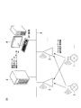
- FIG. 1 is a conceptual diagram of an information display system S1 according to an embodiment of the present invention.
- the information display system S1 is a system for managing and controlling field devices in a plant or factory. Plants include chemical and other industrial plants, plants that manage and control wells in and around gas fields and oil fields, plants that manage and control power generation such as hydropower, thermal power, and nuclear power, and environments such as solar and wind power. There are plants that manage and control power generation, and plants that manage and control water and sewage and dams.
- the information display system S1 includes a field device 1, an access point 2, an information processing device 3, and an information display device 4.
- the field device 1 is, for example, a sensor device such as a flow meter or a temperature sensor, a valve device such as a flow control valve or an on-off valve, an actuator device such as a fan or a motor, a camera or video for photographing a situation or an object in a plant, etc.
- An imaging device an acoustic device such as a microphone or a speaker that collects abnormal sounds or the like in a plant or emits an alarm sound, a position detection device that outputs position information of each device, and other devices.
- the access point 2 is, for example, a backbone router.
- the information processing device 3 is a device that processes information obtained from a plant, and is, for example, a device such as a gateway or a system manager.
- the information display device 4 is a device including a display unit that displays information obtained from a plant by using a GUI (Graphical User Interface).
- the field device 1 and the access point 2 perform wireless communication conforming to an industrial wireless communication standard such as ISA100.11a or WirelessHART (registered trademark).
- the field device 1 can perform redundant communication with a plurality of access points 2 on the first route and the second route. Further, the field device 1 has a function of switching the access point 2 that performs communication as the first route or the second route according to the setting.
- the access point 2, the information processing device 3, and the information display device 4 communicate via the network 5.
- the network 5 is a backbone network, for example.
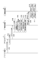
- FIG. 2 is a sequence diagram showing a first example of the operation of the information display system S1.
- the field device 1 acquires process data such as the flow rate, pressure, and temperature of the fluid to be measured, and transmits the acquired process data to the access point 2 via wireless communication (step S101).
- the process data includes transmission time information (time stamp) indicating a transmission time and a sequence number indicating a data number, and is transmitted at a predetermined cycle.
- the access point 2 acquires process data (step S102), and transmits the acquired process data to the information processing apparatus 3 (step S103).
- the information processing apparatus 3 acquires process data (step S104), and based on the acquired process data, sets a reception interval (Interval), a transmission / reception delay (Latency), and a process data loss number (Publication Loss). Calculation is performed (step S105).
- the reception interval, the delay between transmission and reception, and the number of process data loss are communication quality information indicating the communication quality of the communication path from the field device 1 to the information processing apparatus 3. A method for calculating the communication quality information will be described later.
- the information processing device 3 stores the communication quality information of the calculation result as the latest data in the storage unit of the own device (step S106). Next, the information processing device 3 generates statistical information by statistically processing the communication quality information of the calculation result over a predetermined period (step S107).
- the statistical information includes time-series data associated with time and statistical report data.
- the time series data includes minute data, hourly data, and daily data.
- the data per minute is data obtained by statistically processing the communication quality information for one minute.
- the hourly data is data obtained by statistically processing one hour of communication quality information.
- the daily data is data obtained by statistically processing communication quality information for one day.
- the latest data and the time series data include operation state information indicating the operation state of the field device 1.
- the statistical report data is a collection of information for displaying a statistical report described later.
- the information processing apparatus 3 stores the generated statistical information in the storage unit of the own apparatus (step S108).
- the information processing device 3 transmits the latest data, time series data, and statistical report data to the information display device (step S109).
- the information display device 4 acquires the latest data, time series data, and statistical report data (step S110), and displays the acquired information (step S111).
- FIG. 3 is a sequence diagram showing a second example of the operation of the information display system S1.
- the field device 1 transmits communication health information to the access point 2 via wireless communication (step S201).
- the communication soundness information includes the number of successful communication of wireless communication, the number of communication failures, the measured received signal strength, the use channel number, and the number of transmission postpones, and is transmitted at a predetermined cycle. Further, the field device 1 may acquire the communication soundness information for each access point 2 existing in a range where the own device can perform communication.
- the access point 2 acquires communication health information (step S202), and transmits the acquired communication health information to the information processing device 3 (step S203).
- the information processing device 3 acquires communication health information (step S204), and based on the acquired communication health information, the packet error rate (PER), the received signal strength (RSSI), and the transmission see-off rate ( CCA Back off Note that the CCA calculates Clear Channel Association (step S205).
- the packet error rate, received signal strength, and transmission postponing rate are communication quality information. A method for calculating the communication quality information will be described later.
- the information processing device 3 stores the communication quality information of the calculation result as the latest data in the storage unit of the own device (step S206).
- the processing from step S207 to step S211 is the same as the processing from step S107 to step S111 shown in FIG.
- the field device 1 transmits device power information indicating the power state of the device itself to the information processing device 3.
- the device power source information includes information on the remaining battery level.
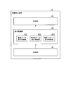
- FIG. 4 is a block diagram illustrating an example of a schematic functional configuration of the information processing apparatus 3.
- the information processing apparatus 3 includes a communication unit 31, a storage unit 32, an acquisition unit 331, a calculation unit 332, a minute data generation unit 333, an hourly data generation unit 334, a daily data generation unit 335, and a statistical report.
- a generation unit 336 and a transmission control unit 337 are provided.
- the information processing apparatus 3 includes a CPU (Central Processing Unit) and a storage device inside the apparatus.
- CPU Central Processing Unit
- the communication unit 31 includes a communication interface connected to the network 5 and communicates with the access point 2 and the information display device 4.
- the storage unit 32 includes, for example, a main storage device such as a ROM (Read Only Memory) and a RAM (Random Access Memory) and an auxiliary storage device.
- these storage devices include, for example, a large-capacity nonvolatile memory such as a flash memory, a large-capacity volatile memory such as a DRAM (Dynamic Random Access Memory), and a small-capacity nonvolatile memory such as a FeRAM (Ferroelectric Random Access Memory). Configured using memory.
- the storage unit 32 stores various programs to be executed by the CPU included in the information processing apparatus 3, such as firmware and application programs, and results of processing executed by the CPU.
- the storage unit 32 stores setting information indicating a transmission time interval of process data for each device.
- the storage unit 32 stores threshold setting information for each device used for the determination process by the statistical report generation unit 336.
- the storage unit 32 stores channel assignment information indicating assignment of used channel numbers of devices to slots.
- the acquisition unit 331, the calculation unit 332, the minute data generation unit 333, the hourly data generation unit 334, the daily data generation unit 335, the statistical report generation unit 336, and the transmission control unit 337 include, for example, information processing
- the CPU provided in the apparatus 3 functions by executing a program stored in the storage unit 32.
- the storage unit 32 includes a recent data storage unit 321, a minute data storage unit 322, an hourly data storage unit 323, a daily data storage unit 324, and a statistical report storage unit 325.
- the latest data storage unit 321 stores the latest data of communication quality information.
- the minute-by-minute data storage unit 322 stores minute-by-minute data, which is communication quality information for each minute obtained by statistically processing the latest data every minute among time-series data.
- the hourly data storage unit 323 stores hourly data that is communication quality information for each hour obtained by statistically processing the hourly data every hour among the time series data.
- the daily data storage unit 324 stores daily data that is daily communication quality information obtained by statistically processing hourly data for each day among time series data.
- the statistical report storage unit 325 stores statistical report data generated from the communication quality information.
- FIG. 5 is a diagram illustrating an example of the types of storage devices that store data processed by the information processing device 3.
- a flash memory has a large capacity and has a characteristic that data is not lost even when the power is turned off, but the lifetime of the number of writing is short.
- This flash memory stores data per minute, hourly data, daily data, route information indicating the connection mode of each device included in the information display system S1, device information indicating the type and setting of each device, identification information, and the like.
- DRAM loses data when power is turned off, but has a large capacity and a long life of writing.
- temporary storage data temporary storage every minute data used for the calculation of the latest data, hourly data, temporary storage data (temporary storage every hour data) used for daily data calculation.
- FeRAM has a small capacity, but has a characteristic that data is not lost when the power is turned off.
- the FeRAM stores index information that is information about the storage position of each data stored in the flash memory.
- the flash memory is non-volatile, but the number of times of writing is limited. Therefore, in the present embodiment, the information processing device 3 reads the latest data having a high update frequency, the minute data calculated based on the latest data, and the hourly data calculated based on the minute data. To temporarily accumulate. Then, after storing the data for every minute and the data for every hour, the number of times of writing to the flash memory is reduced by moving from the DRAM to the flash memory. Thereby, the information processing apparatus 3 can suppress the failure of the flash memory and hold the data more stably. Further, daily data, path information, and device information calculated based on hourly data stored in the DRAM may be directly written into the flash memory because the update frequency is low.
- the acquisition unit 331 acquires process data and communication health information from the access point 2 via the communication unit 31.
- the acquisition unit 331 outputs the acquired process data and communication health information to the calculation unit 332.
- the calculation unit 332 acquires process data and communication health information from the acquisition unit 331, and calculates communication quality information based on the acquired process data and communication health information.
- the calculation unit 332 stores the latest data of the calculated communication quality information in the latest data storage unit 321 and outputs the latest data to the data generation unit 333 every minute.
- the computing unit 332 computes the packet error rate of the communication health information based on the number of communication failures and the number of communication successes included in the communication health information by the following equation (1).
- PER [%] 100 ⁇ communication failure count / (communication success count + communication failure count) (1)
- the parameter of the packet error rate may be determined based on the measurement time and the total number of communication times for determination.
- the computing unit 332 computes the received signal strength by computing the average value of the measured received signal strength included in the communication soundness information. The average value is calculated by, for example, a moving average.
- the computing unit 332 computes the transmission see-off rate of each channel by the following equation (2).
- Transmission miss rate [%] 100 ⁇ (number of transmission misses for each channel) / (total number of transmission slots for each channel) (2)
- the total number of transmission slots for each channel is acquired from the channel assignment information stored in the storage unit 32.
- the calculation unit 332 calculates the number of process data loss indicating the number of lost process data by the following equation (3).
- Number of process data loss (sequence number received most recently) ⁇ (sequence number received last time) ⁇ 1 (3)
- the calculation unit 332 calculates the delay between transmission and reception of process data by the following equation (4).
- Delay between transmission and reception (process data reception time of information processing device 3)-(transmission time added by field device during transmission) (4)
- the calculation unit 332 calculates the process data reception interval by the following equation (5).
- Reception interval ⁇ (Latest reception time) ⁇ (Previous reception time) ⁇ / (Predetermined transmission time interval) (5)
- FIG. 6 is a timing chart showing the number of process data loss, delay between transmission and reception, and reception interval.
- the horizontal axis indicates time.
- 6 shows the transmission time and sequence number of process data transmitted by the field device 1.
- 6 shows the reception time and sequence number of the process data acquired by the information processing apparatus 3 from the field device 1.
- the number of process data loss, the delay between transmission and reception, and the value of the reception interval are shown.
- the internal clocks of the field device 1 and the information processing device 3 are synchronized.
- the field device 1 transmits process data at a predetermined time interval, for example, at intervals of 10 seconds.
- the field device 1 adds 1 to the sequence number at every transmission.
- the information processing apparatus 3 can identify process data lost in the course of communication by confirming the sequence number. For example, as illustrated in FIG. 6, when the information processing apparatus 3 receives the process data with the sequence number “5” after the process data with the sequence number “3”, the sequence number “ It is estimated that the process data of “4” is lost in the communication process. Therefore, the information processing apparatus 3 calculates the number of process data loss at the transmission time “9:00:40” as “1” by the above-described equation (3). Further, the information processing apparatus 3 does not have to determine the number of process data lost when the first process data is received as in the process data of the sequence number “1” illustrated in FIG. 6.
- the delay between transmission and reception indicates the time until the information processing device 3 receives the process data transmitted from the field device 1.
- the process data with the sequence number “2” is transmitted from the field device 1 to “9:00:10” and received by the information processing apparatus 3 at “9:00:13”. ing. Therefore, the information processing device 3 calculates the inter-transmission / reception delay at the transmission time “9:00:10” as “3” seconds by the above-described equation (4). Further, for example, the information processing apparatus 3 does not measure the inter-transmission / reception delay for the lost process data like the process data of the sequence number “4” shown in FIG.
- the reception interval indicates the reception interval of process data in the information processing apparatus 3.
- the information processing apparatus 3 receives the process data with the sequence number “2” at “9:00:13” and the process data with the sequence number “3” is “9:00:22”. Is receiving.
- the process data transmission time interval by the field device 1 is 10 seconds. Therefore, the information processing device 3 calculates the reception interval at the transmission time “9:00:10” as “0.9” times by the above-described equation (5).
- the information processing apparatus 3 after receiving the process data with the sequence number “3” at “9:00:22”, the information processing apparatus 3 does not receive the process data with the sequence number “4”, but the process data with the sequence number “5”. Is received at “9:00:42”. Therefore, the information processing apparatus 3 calculates the reception interval at the transmission time “9:00:20” as “2.0” times.
- the minute data generation unit 333 performs statistical processing on the acquired latest data and generates data every minute. Specifically, the minute data generation unit 333 acquires, for example, the maximum value, the minimum value, and the average value of the latest data for one minute of the communication quality information, and sets it as the minute data of the communication quality information. For the process data loss count, the minute data generation unit 333 acquires, for example, the integrated value of the latest data for one minute of the process data loss count, and sets it as the minute data. For example, when the hourly data generation unit 333 generates the hourly data for one hour on the DRAM, the generated hourly data is stored in the hourly data storage unit 322 of the flash memory, and the hourly data is generated. To the unit 334.
- the hourly data generation unit 334 When the hourly data generation unit 334 acquires the data per minute from the minute data generation unit 333, the hourly data generation unit 334 performs statistical processing on the acquired data per minute to generate hourly data. Specifically, the hourly data generation unit 334 acquires the maximum value, the minimum value, and the average value for the hourly data for one hour of the communication quality information, and sets it as hourly data for the communication quality information. For the process data loss count, the hourly data generation unit 334 acquires, for example, an integrated value of hourly data for one hour of the process data loss count and uses it as hourly data.
- the hourly data generation unit 334 sets the hourly data of the driving state information to an abnormal state. For example, when generating hourly data for one day on the DRAM, the hourly data generation unit 334 stores the generated hourly data in the hourly data storage unit 323 of the flash memory, and outputs the hourly data to the data generation unit 335 every day. .
- the daily data generation unit 335 When the hourly data generation unit 335 acquires the hourly data from the hourly data generation unit 334, the daily data generation unit 335 statistically processes the acquired hourly data to generate the data every day. Statistical processing by the daily data generation unit 335 is the same as that of the minute data generation unit 333 or the hourly data generation unit 334. For example, the daily data generation unit 335 stores the generated daily data in the daily data storage unit 324 of the flash memory.
- the statistical report generation unit 336 reads time-series data such as data per minute from the storage unit 32 and generates statistical report data.
- Statistical report data is communicated by comparing device identification information, process data transmission time interval setting information for each device, threshold setting information for each device, communication quality information statistical information, and a predetermined threshold. This is data in which a determination result for determining quality is associated with device power supply information.
- the latest information among the latest data of the device power supply information is associated with the device power supply information.
- the statistical report generation unit 336 stores the generated statistical report data in the statistical report storage unit 325.
- the statistical report generation unit 336 may determine the quality of communication quality by comparing hourly data or daily data with a predetermined threshold in the statistical information to generate statistical report data.
- the statistical report generation unit 336 may determine the quality of the communication quality based on the latest calculated statistical information, for example, and may determine the communication quality based on the statistical information at an arbitrary time point designated by the user. Good or bad may be determined.
- the transmission control unit 337 transmits data stored in the information processing device 3 to the information display device 4 via the communication unit 31. For example, when the communication unit 31 receives a request for acquiring the latest data from the information display device 4, the transmission control unit 337 reads the latest data from the latest data storage unit 321 and transmits the read latest data to the information display device 4. Further, for example, when the communication unit 31 receives a time-series data acquisition request from the information display device 4, the transmission control unit 337 receives the data from the minute data storage unit 322, the hourly data storage unit 323, or the daily data storage unit 324. Each minute data, hourly data, or daily data is read, and the read time series data is transmitted to the information display device 4. For example, when the communication unit 31 receives an acquisition request for statistical report data from the information display device 4, the transmission control unit 337 reads the statistical report data from the statistical report storage unit 325, and the read statistical report data is displayed on the information display device. 4 to send.
- FIG. 7 is a block diagram illustrating an example of a schematic functional configuration of the information display apparatus according to the present embodiment.
- the information display device 4 is, for example, a personal computer, a mobile phone, a tablet, a smartphone, or a PDA (Personal Digital Assistant), and includes a CPU and a storage device inside the device.
- the information display device 4 includes a display unit 41, a communication unit 42, and a display control unit 43.
- the information display device 4 may include an input device such as a mouse, a keyboard, or a touch panel.
- the display unit 41 includes, for example, a liquid crystal display or an organic EL (Electro-Luminescence) display.
- the communication unit 42 includes a communication interface connected to the network 5 and communicates with the information processing apparatus 3.
- the display control unit 43 acquires data from the information processing device 3 via the communication unit 42 and causes the display unit 41 to display the acquired data.
- the display control unit 43 includes a latest data display control unit 431, a time-series data display control unit 432, and a statistical report display control unit 433.
- the latest data display control unit 431 transmits an acquisition request for the latest data to the information processing device 3.
- the latest data display control unit 431 causes the display unit 41 to display the acquired latest data.
- the time-series data display control unit 432 transmits a time-series data acquisition request to the information processing apparatus 3.
- the time series data display control unit 432 causes the display unit 41 to display the acquired time series data.
- the statistical report display control unit 433 transmits a statistical report data acquisition request to the information processing device 3.
- the statistical report display control unit 433 causes the display unit 41 to display the acquired statistical report data.
- FIG. 8 is a diagram illustrating an example of a display mode when displaying the latest data or the like.
- Area A1 shows the 1st example of the display mode of the screen which information display device 4 displays.
- the information display device 4 displays, for example, a first example of a display mode at the time of system startup or maintenance.
- the area A11 displays a tab indicating the subnet of the wireless network composed of the field device 1 and the access point 2.
- subnet identification information for example, “10001” in FIG. 8
- the state of the subnet are displayed in association with each other.
- the state of the subnet is indicated by changing the color of the icon “ ⁇ ” arranged on the left side of the subnet identification information in accordance with the communication quality of the field device connected to the subnet.
- the tab displayed in the area A11 can be selected, and the area A12 displays information on the field device 1 connected to the subnet indicated by the selected tab. In the example shown in FIG. 8, “All” indicating all the field devices 1 in the wireless network is selected.
- the table shown in the area A12 shows the latest data for each field device.
- the column C11 shows a status icon that represents an overview of the status of the field device 1.
- the information processing device 3 indicates the state of the field device 1 by changing the color of the state icon according to the driving state information.
- the status icon indicates three statuses of “normal”, “abnormal”, and “warning” by three patterns respectively illustrated by items I11, I12, and I13.
- “Device Tag” in the column C121, “Network ID” in the column C122, and “Vendor / Model” in the column C123 indicate device specifying information for specifying the field device 1.
- “Device Role” in the column C13 indicates setting information (role) of the field device 1.
- “Join Status” in column C14 indicates a connection state of the field device to the network. The connection state includes “Full Join” indicating that the connection is established and “Disconnected” indicating that the communication is disconnected.
- “Operation Status” in the column C15 indicates the operation state of the field device 1. The operation state of the field device includes “Published” for transmitting process data and “Not published” for not transmitting process data.
- “Interval” in column C161 indicates the latest data of the reception interval. “Latency” in column C162 indicates the latest data of the delay between transmission and reception. “Primary Router” in column C163 indicates the access point 2 used by the field device 1 as the first route. “RSSI (P)” in column C164 indicates the latest data of the received signal strength of the field device 1 in communication with the access point 2 used as the first route. “PER (P)” in column C165 indicates the most recent data of the packet error rate of the field device 1 in communication with the access point 2 used as the first route.
- “Secondary Router” in column C166 indicates the access point 2 used by the field device 1 as the second route.
- RSSI (P) indicates the latest data of the received signal strength of the field device 1 in communication with the access point 2 used as the second route.
- PER (P) indicates the most recent data of the packet error rate of the field device 1 in communication with the access point 2 used as the second route.
- CCA Back off indicates the latest data of the transmission miss rate and the channel number obtained by calculating the send miss rate.
- the column “Battery Life” in the column C171 and the column “Power Supply Status” in the column C172 indicate device power supply information indicating the power state of each device.
- “Battery Life” indicates the number of days until the battery (battery) remaining amount is zero or the remaining amount is such that the device cannot be operated.
- “Power Supply Status” in the device power supply information indicates the ratio of the remaining battery capacity to the battery capacity.
- a column for displaying the number of process data loss may be provided.
- information obtained by statistically processing the latest data may be displayed in each item of the communication quality information.
- the information display device 4 may display the maximum value among the reception intervals calculated during the period until the screen is updated. For example, when the screen update cycle is 1 minute, the information display device 4 displays data for every minute of the maximum value of the reception interval. Similarly, for example, the information display device 4 may display the maximum value among the delays between transmission and reception calculated during the period until the screen is updated in the item “Latency” in the column C162.
- the information display device 4 for example, in the item “CCA Back off” in column C169, the maximum value of the transmission rate for each channel calculated within a predetermined time is set to the channel indicating the maximum value. It may be displayed with a number. The channel number will be described later in the description of FIG.
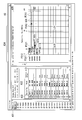
- FIG. 9 is a diagram illustrating an example of a display mode when a statistical report according to the present embodiment is displayed.
- Region A2 shows a second example of the display mode of the screen displayed by information display device 4.
- the information display device 4 displays a second example of the display mode when, for example, the start-up of the system is completed and the system is in an operating state.
- Area A21 displays a list of subnets that make up the wireless network. In the area A21, as in the area A11 in FIG. 8, the subnet identification information and the state of the subnet are displayed in association with each other. In the example shown in FIG. 9, the state of the subnet is indicated by the design of the icon in addition to the color.
- “L” mark in which item I211 is exemplified indicates that all devices in the subnet are normal. “!” Exemplified in item I212 indicates that one or more field devices 1 or access points 2 in the subnet are in a warning state.
- the “x” mark exemplified in the item I213 indicates that there are one or more abnormal devices in the field device 1 or the access point 2 in the subnet.
- the “?” Mark illustrated in the item I214 indicates that the state of the field device 1 or the access point 2 in the subnet is being measured, and the result is an unknown state for which a result has not yet been obtained. In the following, similar marks are used not only to indicate the status of the subnet but also to indicate the status of the device. The meaning of each mark in the case of indicating the state of the device is similar to that described above, “L” is a normal state, “!” Is a warning state, “X” is an abnormal state, “ "?” Indicates that the state is unknown.
- Each subnet displayed in the area A21 can be selected, and the area A22 and the area A23 display information of devices connected to the selected subnet.
- “All” indicating all devices in the wireless network is selected.
- Area A22 indicates the number of devices for each state.
- Items I221, I222, and I223 indicate the number of access points 2 for each state of the device.
- Items I224, I225, and I226 indicate the number of field devices 1 for each device state.
- Items I221 and I224 indicate the number of devices in an abnormal state.
- Items I222 and I225 indicate the number of devices in a warning state.
- Items I223 and I226 indicate the number of devices in an unknown state.
- the table shown in the area A23 shows statistical information for each device.
- the icon shown in the column C21 indicates the role and state of the device.
- the role of the device is indicated by the shape of the icon.
- the outline of “ ⁇ ” like the icon of the item I231 indicates the access point 2.
- the outline of “ ⁇ ” like the icon of the item I232 indicates the field device 1.
- the characters “I” and “R” in the icons of the items I232 and I233 indicate further detailed classification of the field device 1.
- the state of the device may be indicated by, for example, an icon color as described using the items I11, I12, and I13 in FIG.
- the “Device Tag” in the column C221 and the “Model” in the column C222 indicate the device identification information as in the column C121 and the column C123 in FIG. 8, respectively.
- “Publication Period” in column C23 indicates a set value (predetermined transmission time interval) of the process data transmission time interval by the field device 1.
- “Alert Threshold” in the column C24 indicates a setting state of a threshold for determining the state of the field device 1.
- one of two threshold values is set in the field device 1 according to its application.
- the setting of the threshold is indicated by a first threshold “A” and a second threshold “B”.
- the second threshold “B” is a more severe value than the first threshold “A”.
- the first threshold is set, for example, for the field device 1 for monitoring use.
- the second threshold value is set, for example, for a field device 1 for high-speed monitoring that needs to transmit and receive information accurately at short time intervals and a field device 1 for plant control.
- “Status” in column C251 indicates operating state information.
- “Publication Loss” in column C252 indicates a comparison result between the statistical information of the number of process data loss and the threshold value.
- “Interval” in the column C253 indicates a comparison result between the statistical information of the reception interval and the threshold value.
- “Latency” in column C254 indicates a comparison result between the statistical information of the delay between transmission and reception and the threshold value.
- “PER” in column C255 indicates a comparison result between the statistical information of the packet error rate and the threshold value.
- the information display device 4 displays the items in columns C252 to C255 based on the communication state information included in the statistical report data.
- a column for displaying the comparison result between the statistical information of the received signal strength and the transmission see-off rate and the threshold value may be provided.
- “Power Status” in column C26 indicates device power supply information.
- the device power supply information is indicated by an image indicating the power supply state of the device.
- the device power source information is indicated by superimposing information indicating details of the remaining amount of the battery on the image, such as a numerical value indicating the remaining days of the battery.
- the information display device 4 can display a large amount of information in a small area.
- the illustrated image other than the battery indicates a device that is supplied with power from a commercial power source or the like (line connection).
- Area A24 shows a button for changing the display content of the display screen. For example, when the button of the area A24 is pressed, the information display device 4 may display a third example of a display mode to be described later.
- the display of columns C252 to C255 is determined based on statistical information such as an average value or maximum value of communication quality information, for example.
- statistical information such as an average value or maximum value of communication quality information, for example.
- the maximum value of the communication quality information is smaller than the threshold value, it is assumed that the field device 1 is in a normal state for the communication quality information.
- the maximum value of the communication quality information is larger than the threshold value and the average value is equal to or less than the threshold value, it is assumed that the field device 1 is in a warning state for the communication quality information.
- the average value of communication quality information is larger than a threshold value, it is assumed that the field device 1 is in an abnormal state for the communication quality information.
- the statistical information used for displaying the columns C252 to C255 is, for example, data per minute, but the statistical information may be hourly data or daily data.
- FIG. 10 is a table showing an example of a display mode selection method when device power supply information is displayed.
- the “state name” in column C31 indicates the classification of the power supply state of the device.
- Power Supply Status in column C32 indicates the type of power source and the remaining battery level.
- Line Powered indicating that power is supplied from the line (power supply line) and “100-75%”, “75-25%” indicating the remaining battery level, or There are “25-0%” and “Unknown” indicating unknown.
- “Image” in column C33 shows an example of a display mode corresponding to the state of the power source. For example, when “Power Supply Status” in the column C32 is “Line Powered”, an image indicating a line connection associated with the “Line Powered” is selected as “Image”. When the “state name” in the column C31 is “unknown”, an image indicating unknown associated with the “unknown” is selected as the “image”. In addition, when the power source is a battery, an image whose “state name” is “normal” or “warning” is selected from images associated with “Power Supply” corresponding to the remaining battery level. The The image selected in this way is used for displaying the device power information shown in C26 of FIG.
- FIG. 11 is a diagram illustrating an example of a display mode when displaying a distribution of values of communication quality information and the like.
- Region A3 shows a third example of the display mode of the screen displayed by information display device 4.
- the information display device 4 displays the third example of the display mode when there is an abnormal or warning device and communication quality information.
- the information shown in the region A31, the region A32, and the region A33 is the same as the region A21, the region A22, and the region 23 in FIG. 9 described above.
- Area A34 displays a tab indicating communication quality information.
- the communication quality information displayed in the area A34 includes the number of process data loss (“Publication Loss”), the reception interval (“Interval”), the delay between transmission and reception (“Latency”), the packet error rate (“PER”), and the received signal. Strength (“RSSI”) and transmission rate (“CCA Back off”).
- the tab displayed in the area A34 can be selected, and the area A35 displays the distribution of the communication quality information indicated by the selected tab in association with the device identification information. In the example shown in FIG. 11, “PER” is selected, and the distribution of packet error rates is shown in region A35.
- the device displayed in the area A35 may be changeable according to the selection of the subnet in the area A31 or the equipment in the area A33.
- the broken line L31 indicates the first threshold “A” for the communication quality information.
- a broken line L32 indicates the second threshold “B” for the communication quality information.
- the graph G3 is a graph showing the distribution of communication quality information corresponding to the device identification information.
- the horizontal axis of the graph G3 indicates the magnitude of the communication quality information value. Since the field device 1 has two communication routes, the first route and the second route, the graph indicating the distribution of the communication quality information of the first route and the communication of the second route for each piece of device specifying information in the area A35. Two graphs are shown, a graph showing the distribution of quality information. For example, in the example shown in FIG. 11, the distribution of “PER” related to the first route of the field device 1 indicated by the device identification information “DEV002” is shown as a graph G31, and the distribution of “PER” related to the second route is shown in the graph G32. Is shown as
- Each graph showing the distribution of communication quality information is shown as a line connecting points of maximum value, minimum value, and average value respectively exemplified by points P311, P312 and P313, for example.
- each graph of the graph G3 is shown in a mode according to a comparison result between the communication quality information and the threshold value of the device identification information. For example, when the threshold value setting of “DEV002” is the first threshold value “A”, the average value of “PER” indicated by the graph G31 is larger than the first threshold value “A”. The field device 1 is in an abnormal state. Therefore, the point P313 indicating the average value of the graph G31 is indicated by the shape of “x” indicating the abnormal state.
- the graph showing the distribution of communication quality information shows the maximum value, minimum value, and average value of data every minute, but the maximum value, minimum value of hourly data and daily data, And an average value etc. may be shown.
- the point P321 indicating the average value of the graph G313 is indicated by the shape of “ ⁇ ” indicating the normal state.
- the threshold value setting of “DEV003” is the second threshold value “B”
- the maximum value of “PER” indicated by the graph G33 is larger than the second threshold value “B”
- the average value is the first value Since it is smaller than the threshold value “B” of 2
- the point P331 indicating the average value of the graph G33 is indicated by the shape of “ ⁇ ” indicating the warning state.
- Each graph may be displayed in different colors according to the state of the field device 1.
- FIG. 12 is a diagram illustrating an example of a display mode when displaying time-series data of communication quality information and the like.
- Region A4 shows a fourth example of the display mode of the screen displayed by information display device 4.
- the information display device 4 displays, for example, a fourth example of the display mode when there is an abnormal or warning device in the display of the statistical report.
- An area A41 shows device specifying information and settings of the target field device 1 for displaying time-series data.
- Area A42 shows the selection status of communication quality information to be displayed for time-series data. Items that can be selected in the area A42 are substantially the same as those that can be selected in the area A34 of FIG. 11, and the packet error rate and the received signal strength can be selected by distinguishing between the first path and the second path.
- Area A43 shows a graph of time-series data of the communication quality information selected in area A42.
- the time-series data shown in the area A43 is data for every minute, but may be data for every hour or daily data.
- the vertical axis of the graph of the area A43 indicates the magnitude of the communication quality information value.
- the horizontal axis of the graph in the area A43 indicates the date and time.
- a broken line L41 indicates a fluctuation tolerance (Stall Limit) of the reception interval.
- a broken line L42 indicates a threshold value.
- the reception interval “Interval” is selected in the area A42, and the graph G4 of the reception interval “Interval” corresponding to the selection is displayed in the area A43.
- the second threshold “B” is set as the threshold “Threshold” (broken line L42).
- a region A431 indicates a portion where the field device 1 is in a warning state in the graph G4 indicating the time series data of the reception interval.
- a region A432 indicates a portion of the graph G4 in which the maximum value is equal to or less than the threshold value and is in a normal state.
- the marker “ ⁇ ” at point P41 indicates a change in threshold setting or a change in route.
- a region A441 shows details of the change. For example, when the marker at the point P41 is selected by mouse over or the like, the information display device 4 may display the route information of the region A441.
- FIG. 13 is a diagram illustrating an example of a display mode of a threshold setting screen for comparison with statistical information.
- the area A5 shows a fifth example of the display mode of the screen displayed by the information display device 4.
- the area A51 is an area for selecting setting items.
- the area A52 is an area for setting a threshold value to be compared with the statistical information of the communication quality information.
- the area A521 is an area for setting a threshold value related to communication quality information of the field device 1.
- a column C511 of the table shown in the region A521 indicates whether the threshold value to be set is the first threshold value “A” or the second threshold value “B”.
- Column C512 shows the threshold value for the number of process data losses.
- Column C513 indicates the threshold value of the reception interval.
- a column C514 indicates a threshold value for delay between transmission and reception.
- a column C515 indicates a packet error rate threshold.
- Column C516 indicates a threshold value of the received signal strength. Each item in columns C512 to C516 can be selected and input, and a desired value may be set as a threshold value. Further, by setting any item in the columns C512 to C516 to “Disable”, the threshold value may not be set, and the information display device 4 may be set not to notify a warning state or an abnormal state regarding the item.
- a column for setting a threshold value of the transmission send-off rate may be provided.
- Areas A522 and A523 indicate threshold values for the remaining battery level of the field device 1.
- the area A522 is an area for setting the number of days until the battery remaining amount is zero or the remaining amount of the device cannot be operated as a threshold for the device power supply information.
- An area A523 is an area for setting the ratio of the remaining battery capacity to the battery capacity as a threshold for the device power supply information.
- Area A524 is an area for selecting a threshold to be compared with statistical information of communication quality information.
- columns C521, C522, and C523 indicate device identification information.
- a column C524 indicates setting information (role) of the field device 1.
- Column C525 indicates that either the first threshold “A” or the second threshold “B” can be selected as the threshold for the communication quality information.
- the column C526 indicates that the threshold for the device power supply information can be selected from either the remaining amount of zero, the planned number of days until the remaining amount that the device cannot be operated and the ratio of the remaining amount of the battery, or both. .
- FIG. 14 is a diagram illustrating an example of a display mode when displaying the latest data and the like.
- the area A6 shows a sixth example of the display mode of the screen displayed by the information display device 4.
- Items shown in the area A61 are the same as the items shown in the area A11 of FIG.
- the table shown in the area A62 is the same as the table shown in the area A12 in FIG.
- the letter “i” is assigned to the right side of the status icon “ ⁇ ” in the status icon item I61 in the row L61 of the area A62.
- “i-75 dBm” is displayed in the item I62 of “RSSI (S)” in the row L61 of the table in the area A62.
- FIG. 15 is a diagram illustrating an example of a display form of a screen for setting a communication path of the field device 1.
- a region A7 shows a seventh display mode example of the information display device 4.
- the information display device 4 changes the display mode to the seventh example.
- An area A71 indicates device identification information.
- the device identification information is “DEV006”.
- Area A72 shows device identification information of access point 2 on the first route and communication quality information related to access point 2.
- the access point 2 of the first route is “BBR001”, and the received signal strength of the communication quality information is “ ⁇ 65 dBm”.
- Area A73 shows device identification information of access point 2 on the second route and communication quality information related to access point 2.
- the access point 2 of the second route is “BBR002”
- the received signal strength of the communication quality information is “i-75 dBm”.
- the table shown in the area A74 shows information on the access point 2 that can be set as the first route or the second route by the device shown in the region A71. Each row of the table can be selected.
- “Neighbor” in the column C71 and “Vendor / Model” in the column C72 indicate device identification information of the access point 2 that can be set as the first route or the second route by the device indicated in the area A71.
- “Device Role” in column C73 indicates setting information (role).
- “RSSI” in column C74 indicates the received signal strength.
- Area A75 shows a button for setting the access point 2 selected in area A74 as the first route.
- Area A76 shows a button for setting the access point 2 selected in area A74 as the second route.
- Area A77 shows a button for ending the setting of the communication path.
- the received signal strength of “DEV001” shown in row L71 is “ ⁇ 68 dBm”.
- the received signal strength is superior to “ ⁇ 75 dBm” of the received signal strength of the second path shown in the region A73. Therefore, by selecting the row L71 and pressing the button shown in the area A76, “DEV001” may be set as the access point 2 of the second route of “DEV006”, and the communication quality of the second route may be improved. There is.
- the information display device 4 may notify that the delay between transmission and reception is affected when the number of hops changes due to the change in the setting.
- FIG. 16 is a diagram illustrating an example of a time-dependent change in the frequency band used by the field device 1 for communication.
- the vertical axis indicates the frequency band (channel number).
- the horizontal axis indicates time.
- “A” indicates the field device 1 for normal monitoring, for which the first threshold is set.
- “B” indicates the field device 1 for high-speed monitoring or control for which the second threshold is set.
- the information processing device 3 detects an abnormality of the channel “11” in the time zone T81. Abnormality about the channel is determined by, for example, the transmission transmission rate and the threshold value described above.
- the field device 1 “B” requires better communication quality. Therefore, after the time zone T81, the channel “11” in which the abnormality is detected is not assigned to the field device 1 “B”, and the frequency band from the channels “17” to “22” as shown in the region A81. Is assigned.
- the field device 1 “A” for normal monitoring does not require communication quality as excellent as the field device 1 “B”. Further, the number of channels that can be used by the field device 1 is limited. Therefore, after the time period T81, the field device 1 “A” is proactively assigned the channel “11”, and the field device 1 “B” is set to be easily used preferentially. Has been. Thereby, it is possible to maintain communication constancy in the entire system while avoiding a shortage of channel resources. Such setting may be performed manually or automatically.
- the information display device 4 uses the information processing device 3 to display communication quality information indicating the communication quality between the display unit 41 and the field device 1 installed in the plant and the information processing device 3. And a display control unit 43 that displays statistical information obtained by performing statistical processing over a predetermined period on the display unit 41 in association with device specifying information for specifying the field device 1.
- the information display apparatus 4 can show the stability of the communication path over a long period of time in an easily understandable manner.
- the display control unit 43 causes the display unit 41 to display device power information indicating the remaining battery level of the field device 1 in association with the device identification information.
- the information display device 4 can indicate the remaining battery level of the field device 1 in an easily understandable manner. Therefore, the user of the information display device 4 can maintain the stability of the communication path.
- the display control unit 43 causes the display unit 41 to display the comparison result between the statistical information and the threshold value set for determining whether the communication quality of the field device 1 is good or not, corresponding to the device identification information.
- the information display device 4 can easily show whether or not the state of the communication path is good without checking the numerical values of the statistical information. Therefore, the information display device 4 can more easily show the stability of the communication path over a long period of time.
- the information display device 4 can easily indicate whether or not the state of the communication path is good based on the determination criterion according to the application of the field device 1. Therefore, the information display device 4 can more easily show the stability of the communication path over a long period of time.
- the display control unit 43 causes the display unit 41 to display the distribution of communication quality information in a predetermined period such as 1 minute or 1 hour in association with the device identification information.
- the display control unit 43 causes the display unit 41 to display statistical information together with the distribution of communication quality information. Accordingly, the information display device 4 can simply indicate the communication quality of the communication path from the past to the present, for example. Therefore, the information display device 4 can more easily show the stability of the communication path over a long period of time.
- the display control unit 43 further causes the display unit 41 to display the change over time of the communication quality information.
- the information display apparatus 4 can show the communication quality details of the communication path from the past to the present. Therefore, the information display device 4 can more easily show the stability of the communication path over a long period of time.
- the display control unit 43 uses other communication in which the communication quality indicated by the communication quality information for the same field device 1 is superior to the access point 2 of the communication path currently used by the field device 1.
- a notification indicating that the route access point 2 exists is displayed on the display unit 41 in association with the device identification information. Thereby, the user of the information display device 4 can set a communication path with higher communication quality for the field device 1.
- the information processing device 3 includes a calculation unit 332 that obtains communication quality information indicating communication quality of the field device 1 using at least one of communication health information and process data transmitted from the field device 1 installed in the plant;
- the statistical data processing unit 333, the hourly data generation unit 334, and the daily data generation as statistical processing units that obtain statistical information by statistically processing the communication quality information obtained by the arithmetic unit 332 over a predetermined period.
- a transmission control unit 337 as an output unit that outputs statistical information obtained by the statistical processing unit.
- the information processing apparatus 3 can generate and output data that easily shows the stability of the communication path over a long period of time.
- the information display device 4 displays the transmission postponing rate.
- the user of the information display device 4 can determine which is caused by insufficient received signal strength or interference by external noise. Therefore, for example, the user of the information display device 4 can more appropriately set the hopping pattern of the channel used by the field device 1 and improve the communication quality of the communication path.
- the information display device 4 displays the received signal strength. Thereby, the user of the information display device 4 can determine, for example, that an obstacle has occurred in the communication path or that the installation position of the field device 1 is inappropriate. In addition, the user of the information display device 4 can determine whether the occurrence of the obstacle is temporary due to, for example, passage of a large vehicle or long-term due to plant growth. it can. Then, the user of the information display device 4 appropriately selects measures such as equipment rearrangement, use of an extension antenna, use of a high gain antenna, and entry prohibition measures in the wireless path, and improves the communication quality of the communication path. be able to.
- the information display device 4 displays the reception interval.
- the user of the information display device 4 can confirm, for example, how much margin the calculated reception interval has with respect to the fluctuation tolerance, so that the communication quality of the communication path can be more accurately determined. Can be confirmed.
- the user of the information display device 4 can appropriately select a countermeasure such as adding a retry slot used by the field device 1 and improve the communication quality of the communication path.
- the information display device 4 displays the delay between transmission and reception. Thereby, since the user of the information display apparatus 4 can confirm the degree of occurrence of delay in signal transmission / reception, for example, the communication quality of the communication path can be confirmed more accurately. In addition, when there is an abnormality in the delay between transmission and reception, the user of the information display device 4 can appropriately select measures such as reducing the number of hops in the communication path and improve the communication quality of the communication path.
- the information display device 4 displays the number of process data loss. Unlike the packet error rate which does not indicate whether or not the process data has actually reached the transmission destination through retry or communication on a redundant path, the number of process data loss can indicate this information. Therefore, the user of the information display device 4 can accurately determine the communication quality of the wireless communication based on the same standard as the wired communication in which the communication quality is determined based on whether or not the process data has arrived.
- any item may be displayed.
- the table shown in the area A23 in FIG. 9 may include an item indicating the comparison result between the statistical information of the received signal strength and the threshold value, for example.
- an arbitrary item may be associated with information and displayed in a color-coded manner. For example, when “Join Status” in the column C14 shown in the area A12 of FIG. 8 is “Disconnected”, the information display device 4 may display the corresponding item in red letters to indicate that it is in an abnormal state.
- the information display device 4 displays the corresponding item in yellow characters and displays a warning state. You may show that. Further, for example, when “RSSI (P)” in column C164 and “RSSI (S)” in column C167 are smaller than a predetermined threshold, the information display device 4 displays the corresponding item in yellow characters and displays a warning state. You may show that there is. For example, when “Battery Life” in the column C171 is smaller than a predetermined threshold, the information display device 4 may display the corresponding item in yellow characters to indicate a warning state.
- the color coding may be performed not by changing the character color but by, for example, filling a cell or character.
- the information processing device 3 may express information by performing hatching or underlining.
- the information display device 4 may display information using an arbitrary visual effect.
- the statistical information shown in the display example of the screen display of the information display device 4 described above may be statistically processed over an arbitrary period.
- each item in the columns C252 to C255 shown in the area A23 in FIG. 9 may be, for example, a comparison result between the hourly data and the threshold value, or may be a comparison result between the hourly data and the threshold value.
- the graph shown in the area A43 in FIG. 12 may be any of minute data, hourly data, and daily data.
- the information processing device 3 may statistically process communication quality information without being limited to the above-described period of 1 minute, 1 hour, or 1 day.
- the information processing apparatus 3 may calculate statistical information from communication quality information in an arbitrary period such as 5 minutes or half a day.
- the example in which the field device 1 and the access point 2 are connected via a wireless network has been described.
- the field device 1 and the access point 2 may be connected by wire.
- the information processing device 3 does not have to calculate the received signal strength that specifically matches the determination of the communication quality of wireless communication.
- a part of the information processing device 3 and the information display device 4 in each of the above-described embodiments for example, the acquisition unit 331, the calculation unit 332, the minute data generation unit 333, the hourly data generation unit 334, the daily data generation unit 335, The statistical report generation unit 336, the transmission control unit 337, the display control unit 43, and the like may be realized by a computer.
- a program for realizing this function may be recorded on a computer-readable recording medium, and the program recorded on this recording medium may be read into a computer system and executed.
- the “computer system” is a computer system built in the information processing apparatus 3 and the information display apparatus 4 and includes hardware such as an OS (Operating System) and peripheral devices.
- the “computer-readable recording medium” means a storage device such as a flexible disk, a magneto-optical disk, a portable medium such as a ROM and a CD-ROM, and a hard disk incorporated in a computer system.
- the program may be a program for realizing a part of the functions described above, and may be a program capable of realizing the functions described above in combination with a program already recorded in a computer system.
- a part or all of the information processing apparatus 3 and the information display apparatus 4 in the above-described embodiment may be realized as an integrated circuit such as an LSI (Large Scale Integration).
- LSI Large Scale Integration
- Each functional unit of the information processing device 3 and the information display device 4 may be individually made into a processor, or a part or all of them may be integrated into a processor.
- the method of circuit integration is not limited to LSI, and may be realized by a dedicated circuit or a general-purpose processor.
- an integrated circuit based on the technology may be used.
- the information processing device 3 and the information display device 4 may be integrated as a device.
Landscapes
- Engineering & Computer Science (AREA)
- Computer Networks & Wireless Communication (AREA)
- Signal Processing (AREA)
- Environmental & Geological Engineering (AREA)
- Data Mining & Analysis (AREA)
- Physics & Mathematics (AREA)
- General Physics & Mathematics (AREA)
- Automation & Control Theory (AREA)
- Testing And Monitoring For Control Systems (AREA)
- Mobile Radio Communication Systems (AREA)
- Maintenance And Management Of Digital Transmission (AREA)
Abstract
L'invention concerne un dispositif d'affichage d'informations pourvu d'une unité d'affichage et d'une unité de commande d'affichage. L'unité de commande d'affichage amène des informations statistiques, obtenues en traitant de manière statistique, sur une période prédéfinie et à l'aide d'un dispositif de traitement d'informations, des informations de qualité de communication indiquant la qualité de communication entre un appareil de champ installé dans une installation et le dispositif de traitement d'informations, à être affichées par l'unité d'affichage en correspondance avec des informations de spécification d'appareil destinées à spécifier l'appareil de champ.
Priority Applications (3)
| Application Number | Priority Date | Filing Date | Title |
|---|---|---|---|
| CN201580006891.4A CN105960793B (zh) | 2014-02-04 | 2015-01-14 | 信息显示装置、信息处理装置、信息显示系统及信息显示方法 |
| EP15746892.7A EP3104582B1 (fr) | 2014-02-04 | 2015-01-14 | Dispositif de traitement d'informations, système et procédé d'affichage d'informations |
| US15/111,519 US10361929B2 (en) | 2014-02-04 | 2015-01-14 | Information displaying device, information processing device, information displaying system, and information displaying method |
Applications Claiming Priority (2)
| Application Number | Priority Date | Filing Date | Title |
|---|---|---|---|
| JP2014019594A JP6135529B2 (ja) | 2014-02-04 | 2014-02-04 | 情報表示装置、情報処理装置、情報表示システム、および情報表示方法 |
| JP2014-019594 | 2014-02-04 |
Publications (1)
| Publication Number | Publication Date |
|---|---|
| WO2015118914A1 true WO2015118914A1 (fr) | 2015-08-13 |
Family
ID=53777722
Family Applications (1)
| Application Number | Title | Priority Date | Filing Date |
|---|---|---|---|
| PCT/JP2015/050739 Ceased WO2015118914A1 (fr) | 2014-02-04 | 2015-01-14 | Dispositif d'affichage d'informations, dispositif de traitement d'informations, système et procédé d'affichage d'informations |
Country Status (5)
| Country | Link |
|---|---|
| US (1) | US10361929B2 (fr) |
| EP (1) | EP3104582B1 (fr) |
| JP (1) | JP6135529B2 (fr) |
| CN (1) | CN105960793B (fr) |
| WO (1) | WO2015118914A1 (fr) |
Cited By (2)
| Publication number | Priority date | Publication date | Assignee | Title |
|---|---|---|---|---|
| JP2018190103A (ja) * | 2017-04-28 | 2018-11-29 | 横河電機株式会社 | 電池管理装置、電池管理システム、および電池管理方法 |
| US10911970B2 (en) | 2015-12-31 | 2021-02-02 | Huawei Technologies Co., Ltd. | Method and apparatus for detecting time series data |
Families Citing this family (21)
| Publication number | Priority date | Publication date | Assignee | Title |
|---|---|---|---|---|
| JP2017211839A (ja) | 2016-05-25 | 2017-11-30 | 横河電機株式会社 | 機器保全装置、機器保全方法、機器保全プログラム及び記録媒体 |
| US11675808B2 (en) | 2016-06-19 | 2023-06-13 | Data.World, Inc. | Dataset analysis and dataset attribute inferencing to form collaborative datasets |
| US11468049B2 (en) | 2016-06-19 | 2022-10-11 | Data.World, Inc. | Data ingestion to generate layered dataset interrelations to form a system of networked collaborative datasets |
| US11947554B2 (en) | 2016-06-19 | 2024-04-02 | Data.World, Inc. | Loading collaborative datasets into data stores for queries via distributed computer networks |
| US10515085B2 (en) | 2016-06-19 | 2019-12-24 | Data.World, Inc. | Consolidator platform to implement collaborative datasets via distributed computer networks |
| US10853376B2 (en) | 2016-06-19 | 2020-12-01 | Data.World, Inc. | Collaborative dataset consolidation via distributed computer networks |
| US11755602B2 (en) | 2016-06-19 | 2023-09-12 | Data.World, Inc. | Correlating parallelized data from disparate data sources to aggregate graph data portions to predictively identify entity data |
| US11941140B2 (en) | 2016-06-19 | 2024-03-26 | Data.World, Inc. | Platform management of integrated access of public and privately-accessible datasets utilizing federated query generation and query schema rewriting optimization |
| US10324925B2 (en) | 2016-06-19 | 2019-06-18 | Data.World, Inc. | Query generation for collaborative datasets |
| US10452975B2 (en) | 2016-06-19 | 2019-10-22 | Data.World, Inc. | Platform management of integrated access of public and privately-accessible datasets utilizing federated query generation and query schema rewriting optimization |
| JP6477662B2 (ja) | 2016-10-28 | 2019-03-06 | 横河電機株式会社 | アンテナモジュール |
| US11068453B2 (en) * | 2017-03-09 | 2021-07-20 | data.world, Inc | Determining a degree of similarity of a subset of tabular data arrangements to subsets of graph data arrangements at ingestion into a data-driven collaborative dataset platform |
| JP7131015B2 (ja) * | 2018-03-26 | 2022-09-06 | 横河電機株式会社 | 情報取得装置、ゲートウェイ装置、プログラム、記録媒体、および方法 |
| US11947529B2 (en) | 2018-05-22 | 2024-04-02 | Data.World, Inc. | Generating and analyzing a data model to identify relevant data catalog data derived from graph-based data arrangements to perform an action |
| US12117997B2 (en) | 2018-05-22 | 2024-10-15 | Data.World, Inc. | Auxiliary query commands to deploy predictive data models for queries in a networked computing platform |
| EP3576349B1 (fr) * | 2018-05-31 | 2021-09-01 | ABB Power Grids Switzerland AG | Surveillance de l'état des réseaux sans fil dans des installations industrielles |
| JP6708241B2 (ja) * | 2018-11-09 | 2020-06-10 | 横河電機株式会社 | 機器保全装置、機器保全方法、機器保全プログラム及び記録媒体 |
| JPWO2021084616A1 (ja) * | 2019-10-29 | 2021-11-18 | 株式会社パトライト | 通信システム |
| JP6844726B2 (ja) * | 2020-02-12 | 2021-03-17 | 住友電気工業株式会社 | センサ情報処理装置および処理プログラム |
| US11947600B2 (en) | 2021-11-30 | 2024-04-02 | Data.World, Inc. | Content addressable caching and federation in linked data projects in a data-driven collaborative dataset platform using disparate database architectures |
| JPWO2024180621A1 (fr) * | 2023-02-27 | 2024-09-06 |
Citations (3)
| Publication number | Priority date | Publication date | Assignee | Title |
|---|---|---|---|---|
| JP2009165099A (ja) * | 2007-12-14 | 2009-07-23 | Yokogawa Electric Corp | 無線通信品質推定システムおよび無線通信品質推定方法 |
| US20130077477A1 (en) * | 2009-11-04 | 2013-03-28 | Aramco Services Company | Adaptive hybrid wireless and wired process control system and method |
| JP2013114471A (ja) * | 2011-11-29 | 2013-06-10 | Yokogawa Electric Corp | フィールド無線監視表示装置 |
Family Cites Families (18)
| Publication number | Priority date | Publication date | Assignee | Title |
|---|---|---|---|---|
| US6985465B2 (en) * | 2000-07-07 | 2006-01-10 | Koninklijke Philips Electronics N.V. | Dynamic channel selection scheme for IEEE 802.11 WLANs |
| JP2003244146A (ja) * | 2002-02-19 | 2003-08-29 | Hitachi Ltd | ネットワーク監視装置におけるトラフィックトレンドリプレイ表示装置 |
| US7697549B2 (en) * | 2002-08-07 | 2010-04-13 | Extricom Ltd. | Wireless LAN control over a wired network |
| US7020438B2 (en) * | 2003-01-09 | 2006-03-28 | Nokia Corporation | Selection of access point in a wireless communication system |
| US20050052992A1 (en) * | 2003-08-01 | 2005-03-10 | Cloonan Thomas J. | Method and system for dynamically managing cable data bandwidth based on channel congestion state and subscriber usage profile |
| US20080188972A1 (en) * | 2006-10-11 | 2008-08-07 | Fisher-Rosemount Systems, Inc. | Method and System for Detecting Faults in a Process Plant |
| US8081787B2 (en) * | 2006-12-20 | 2011-12-20 | Phonak Ag | Hearing assistance system and method of operating the same |
| CA2573711A1 (fr) * | 2007-01-10 | 2008-07-10 | Hydro Quebec | Controle gamma de l'equivalent en eau de la neige et de l'humidite du sol |
| WO2008114450A1 (fr) * | 2007-03-20 | 2008-09-25 | Fujitsu Limited | Procédé de mesure, dispositif de mesure et programme informatique |
| GB0725276D0 (en) * | 2007-12-28 | 2008-02-06 | Vibration Technology Ltd | Seismic data recording |
| CN101583140A (zh) * | 2009-05-14 | 2009-11-18 | 复旦大学 | 通信网络自动化监测系统及其实现方法 |
| US8737244B2 (en) | 2010-11-29 | 2014-05-27 | Rosemount Inc. | Wireless sensor network access point and device RF spectrum analysis system and method |
| JP5299440B2 (ja) | 2011-01-13 | 2013-09-25 | 横河電機株式会社 | 経路設定装置、経路設定方法、管理装置、管理システム、及び記録媒体 |
| JP5664315B2 (ja) * | 2011-02-15 | 2015-02-04 | 富士通株式会社 | 管理装置、管理プログラムおよび管理方法 |
| KR101861545B1 (ko) * | 2012-01-02 | 2018-05-29 | 삼성전자주식회사 | 저장 장치의 데이터 관리 방법 |
| US8655307B1 (en) * | 2012-10-26 | 2014-02-18 | Lookout, Inc. | System and method for developing, updating, and using user device behavioral context models to modify user, device, and application state, settings and behavior for enhanced user security |
| US9154996B2 (en) | 2013-06-12 | 2015-10-06 | Honeywell International Inc. | Apparatus and method for maintaining reliability of wireless network having asymmetric or other low quality wireless links |
| US20150222504A1 (en) * | 2014-02-03 | 2015-08-06 | Apigee Corporation | System and method for monitoring and reporting data in api processing systems |
-
2014
- 2014-02-04 JP JP2014019594A patent/JP6135529B2/ja active Active
-
2015
- 2015-01-14 WO PCT/JP2015/050739 patent/WO2015118914A1/fr not_active Ceased
- 2015-01-14 CN CN201580006891.4A patent/CN105960793B/zh active Active
- 2015-01-14 EP EP15746892.7A patent/EP3104582B1/fr active Active
- 2015-01-14 US US15/111,519 patent/US10361929B2/en active Active
Patent Citations (3)
| Publication number | Priority date | Publication date | Assignee | Title |
|---|---|---|---|---|
| JP2009165099A (ja) * | 2007-12-14 | 2009-07-23 | Yokogawa Electric Corp | 無線通信品質推定システムおよび無線通信品質推定方法 |
| US20130077477A1 (en) * | 2009-11-04 | 2013-03-28 | Aramco Services Company | Adaptive hybrid wireless and wired process control system and method |
| JP2013114471A (ja) * | 2011-11-29 | 2013-06-10 | Yokogawa Electric Corp | フィールド無線監視表示装置 |
Non-Patent Citations (1)
| Title |
|---|
| See also references of EP3104582A4 * |
Cited By (4)
| Publication number | Priority date | Publication date | Assignee | Title |
|---|---|---|---|---|
| US10911970B2 (en) | 2015-12-31 | 2021-02-02 | Huawei Technologies Co., Ltd. | Method and apparatus for detecting time series data |
| EP3393085B1 (fr) * | 2015-12-31 | 2022-05-11 | Huawei Technologies Co., Ltd. | Procédé et dispositif de détection de données de séquence de temps |
| US11979761B2 (en) | 2015-12-31 | 2024-05-07 | Huawei Technologies Co., Ltd. | Method and apparatus for detecting time series data |
| JP2018190103A (ja) * | 2017-04-28 | 2018-11-29 | 横河電機株式会社 | 電池管理装置、電池管理システム、および電池管理方法 |
Also Published As
| Publication number | Publication date |
|---|---|
| CN105960793A (zh) | 2016-09-21 |
| US20160352592A1 (en) | 2016-12-01 |
| JP6135529B2 (ja) | 2017-05-31 |
| EP3104582B1 (fr) | 2020-11-25 |
| US10361929B2 (en) | 2019-07-23 |
| JP2015146562A (ja) | 2015-08-13 |
| EP3104582A1 (fr) | 2016-12-14 |
| EP3104582A4 (fr) | 2017-11-01 |
| CN105960793B (zh) | 2019-10-11 |
Similar Documents
| Publication | Publication Date | Title |
|---|---|---|
| JP6135529B2 (ja) | 情報表示装置、情報処理装置、情報表示システム、および情報表示方法 | |
| EP3007369B1 (fr) | Procédé, dispositif et système de notification d'un événement de communications | |
| US7956766B2 (en) | Apparatus operating system | |
| EP3133741B1 (fr) | Procédé de commande de dispositif électronique portable, appareil central et dispositif | |
| JP6091981B2 (ja) | 月経開始予定日算出装置およびプログラム | |
| JP2020514660A (ja) | 空気調和機及びその制御方法、装置ならびにコンピュータ読み取り可能な記憶媒体 | |
| US20200015163A1 (en) | Scanning Method and Device | |
| US10830862B2 (en) | Position measuring system including a server and a plurality of beacons | |
| JP6478669B2 (ja) | アクセスポイント位置最適化装置及び方法 | |
| CN114063877A (zh) | 储能设备数据显示方法、装置与设备 | |
| US20130110302A1 (en) | Methods, Systems and Apparatus for Power Management | |
| JP2016114361A (ja) | 測位方法、サーバ及びプログラム | |
| JP2016111528A (ja) | 管理装置、端末、機器、管理システム、制御方法、および制御プログラム | |
| CN103475511A (zh) | 用于网络维护的方法及装置 | |
| JP2021025801A (ja) | 評価システム、評価装置、評価方法、およびプログラム | |
| JP6191897B1 (ja) | エネルギー管理装置およびエネルギー管理方法 | |
| US9992559B2 (en) | Sensor management device, sensor, monitoring system, sensor management method, sensor management program, monitoring method, and monitoring program | |
| JP2018019592A (ja) | エネルギー管理装置およびエネルギー管理方法 | |
| JP2018205960A (ja) | 監視制御システム、分散サーバ及び監視制御方法 | |
| JP2017227442A (ja) | 無線通信システム、アクセスポイント、制御装置および位置算出方法 | |
| JP2009224907A (ja) | 無線通信システムおよびそれに用いる通信経路設定用プログラム | |
| CN118646990A (zh) | 电子围栏的应用方法、装置、通信设备和存储介质 | |
| JP6077987B2 (ja) | 無線周波数管理装置および方法 | |
| JP2006325129A (ja) | プレゼンス情報提供システム | |
| US8755356B1 (en) | Methods and systems for dynamically selecting requested forward-link data rate based on C/I ratio |
Legal Events
| Date | Code | Title | Description |
|---|---|---|---|
| 121 | Ep: the epo has been informed by wipo that ep was designated in this application |
Ref document number: 15746892 Country of ref document: EP Kind code of ref document: A1 |
|
| REEP | Request for entry into the european phase |
Ref document number: 2015746892 Country of ref document: EP |
|
| WWE | Wipo information: entry into national phase |
Ref document number: 15111519 Country of ref document: US Ref document number: 2015746892 Country of ref document: EP |
|
| NENP | Non-entry into the national phase |
Ref country code: DE |