WO2015118921A1 - 化学蓄熱装置 - Google Patents
化学蓄熱装置 Download PDFInfo
- Publication number
- WO2015118921A1 WO2015118921A1 PCT/JP2015/050953 JP2015050953W WO2015118921A1 WO 2015118921 A1 WO2015118921 A1 WO 2015118921A1 JP 2015050953 W JP2015050953 W JP 2015050953W WO 2015118921 A1 WO2015118921 A1 WO 2015118921A1
- Authority
- WO
- WIPO (PCT)
- Prior art keywords
- valve
- adsorber
- reactor
- heat storage
- pressure
- Prior art date
- Legal status (The legal status is an assumption and is not a legal conclusion. Google has not performed a legal analysis and makes no representation as to the accuracy of the status listed.)
- Ceased
Links
Images






Classifications
-
- F—MECHANICAL ENGINEERING; LIGHTING; HEATING; WEAPONS; BLASTING
- F28—HEAT EXCHANGE IN GENERAL
- F28D—HEAT-EXCHANGE APPARATUS, NOT PROVIDED FOR IN ANOTHER SUBCLASS, IN WHICH THE HEAT-EXCHANGE MEDIA DO NOT COME INTO DIRECT CONTACT
- F28D20/00—Heat storage plants or apparatus in general; Regenerative heat-exchange apparatus not covered by groups F28D17/00 or F28D19/00
- F28D20/003—Heat storage plants or apparatus in general; Regenerative heat-exchange apparatus not covered by groups F28D17/00 or F28D19/00 using thermochemical reactions
-
- F—MECHANICAL ENGINEERING; LIGHTING; HEATING; WEAPONS; BLASTING
- F01—MACHINES OR ENGINES IN GENERAL; ENGINE PLANTS IN GENERAL; STEAM ENGINES
- F01N—GAS-FLOW SILENCERS OR EXHAUST APPARATUS FOR MACHINES OR ENGINES IN GENERAL; GAS-FLOW SILENCERS OR EXHAUST APPARATUS FOR INTERNAL-COMBUSTION ENGINES
- F01N13/00—Exhaust or silencing apparatus characterised by constructional features
- F01N13/009—Exhaust or silencing apparatus characterised by constructional features having two or more separate purifying devices arranged in series
-
- F—MECHANICAL ENGINEERING; LIGHTING; HEATING; WEAPONS; BLASTING
- F01—MACHINES OR ENGINES IN GENERAL; ENGINE PLANTS IN GENERAL; STEAM ENGINES
- F01N—GAS-FLOW SILENCERS OR EXHAUST APPARATUS FOR MACHINES OR ENGINES IN GENERAL; GAS-FLOW SILENCERS OR EXHAUST APPARATUS FOR INTERNAL-COMBUSTION ENGINES
- F01N3/00—Exhaust or silencing apparatus having means for purifying, rendering innocuous, or otherwise treating exhaust
- F01N3/08—Exhaust or silencing apparatus having means for purifying, rendering innocuous, or otherwise treating exhaust for rendering innocuous
- F01N3/10—Exhaust or silencing apparatus having means for purifying, rendering innocuous, or otherwise treating exhaust for rendering innocuous by thermal or catalytic conversion of noxious components of exhaust
-
- F—MECHANICAL ENGINEERING; LIGHTING; HEATING; WEAPONS; BLASTING
- F01—MACHINES OR ENGINES IN GENERAL; ENGINE PLANTS IN GENERAL; STEAM ENGINES
- F01N—GAS-FLOW SILENCERS OR EXHAUST APPARATUS FOR MACHINES OR ENGINES IN GENERAL; GAS-FLOW SILENCERS OR EXHAUST APPARATUS FOR INTERNAL-COMBUSTION ENGINES
- F01N3/00—Exhaust or silencing apparatus having means for purifying, rendering innocuous, or otherwise treating exhaust
- F01N3/08—Exhaust or silencing apparatus having means for purifying, rendering innocuous, or otherwise treating exhaust for rendering innocuous
- F01N3/10—Exhaust or silencing apparatus having means for purifying, rendering innocuous, or otherwise treating exhaust for rendering innocuous by thermal or catalytic conversion of noxious components of exhaust
- F01N3/103—Oxidation catalysts for HC and CO only
-
- F—MECHANICAL ENGINEERING; LIGHTING; HEATING; WEAPONS; BLASTING
- F01—MACHINES OR ENGINES IN GENERAL; ENGINE PLANTS IN GENERAL; STEAM ENGINES
- F01N—GAS-FLOW SILENCERS OR EXHAUST APPARATUS FOR MACHINES OR ENGINES IN GENERAL; GAS-FLOW SILENCERS OR EXHAUST APPARATUS FOR INTERNAL-COMBUSTION ENGINES
- F01N3/00—Exhaust or silencing apparatus having means for purifying, rendering innocuous, or otherwise treating exhaust
- F01N3/08—Exhaust or silencing apparatus having means for purifying, rendering innocuous, or otherwise treating exhaust for rendering innocuous
- F01N3/10—Exhaust or silencing apparatus having means for purifying, rendering innocuous, or otherwise treating exhaust for rendering innocuous by thermal or catalytic conversion of noxious components of exhaust
- F01N3/18—Exhaust or silencing apparatus having means for purifying, rendering innocuous, or otherwise treating exhaust for rendering innocuous by thermal or catalytic conversion of noxious components of exhaust characterised by methods of operation; Control
- F01N3/20—Exhaust or silencing apparatus having means for purifying, rendering innocuous, or otherwise treating exhaust for rendering innocuous by thermal or catalytic conversion of noxious components of exhaust characterised by methods of operation; Control specially adapted for catalytic conversion
- F01N3/2006—Periodically heating or cooling catalytic reactors, e.g. at cold starting or overheating
-
- F—MECHANICAL ENGINEERING; LIGHTING; HEATING; WEAPONS; BLASTING
- F01—MACHINES OR ENGINES IN GENERAL; ENGINE PLANTS IN GENERAL; STEAM ENGINES
- F01N—GAS-FLOW SILENCERS OR EXHAUST APPARATUS FOR MACHINES OR ENGINES IN GENERAL; GAS-FLOW SILENCERS OR EXHAUST APPARATUS FOR INTERNAL-COMBUSTION ENGINES
- F01N3/00—Exhaust or silencing apparatus having means for purifying, rendering innocuous, or otherwise treating exhaust
- F01N3/08—Exhaust or silencing apparatus having means for purifying, rendering innocuous, or otherwise treating exhaust for rendering innocuous
- F01N3/10—Exhaust or silencing apparatus having means for purifying, rendering innocuous, or otherwise treating exhaust for rendering innocuous by thermal or catalytic conversion of noxious components of exhaust
- F01N3/18—Exhaust or silencing apparatus having means for purifying, rendering innocuous, or otherwise treating exhaust for rendering innocuous by thermal or catalytic conversion of noxious components of exhaust characterised by methods of operation; Control
- F01N3/20—Exhaust or silencing apparatus having means for purifying, rendering innocuous, or otherwise treating exhaust for rendering innocuous by thermal or catalytic conversion of noxious components of exhaust characterised by methods of operation; Control specially adapted for catalytic conversion
- F01N3/206—Adding periodically or continuously substances to exhaust gases for promoting purification, e.g. catalytic material in liquid form, NOx reducing agents
- F01N3/2066—Selective catalytic reduction [SCR]
-
- F—MECHANICAL ENGINEERING; LIGHTING; HEATING; WEAPONS; BLASTING
- F01—MACHINES OR ENGINES IN GENERAL; ENGINE PLANTS IN GENERAL; STEAM ENGINES
- F01N—GAS-FLOW SILENCERS OR EXHAUST APPARATUS FOR MACHINES OR ENGINES IN GENERAL; GAS-FLOW SILENCERS OR EXHAUST APPARATUS FOR INTERNAL-COMBUSTION ENGINES
- F01N5/00—Exhaust or silencing apparatus combined or associated with devices profiting by exhaust energy
- F01N5/02—Exhaust or silencing apparatus combined or associated with devices profiting by exhaust energy the devices using heat
-
- F—MECHANICAL ENGINEERING; LIGHTING; HEATING; WEAPONS; BLASTING
- F28—HEAT EXCHANGE IN GENERAL
- F28F—DETAILS OF HEAT-EXCHANGE AND HEAT-TRANSFER APPARATUS, OF GENERAL APPLICATION
- F28F27/00—Control arrangements or safety devices specially adapted for heat-exchange or heat-transfer apparatus
-
- F—MECHANICAL ENGINEERING; LIGHTING; HEATING; WEAPONS; BLASTING
- F01—MACHINES OR ENGINES IN GENERAL; ENGINE PLANTS IN GENERAL; STEAM ENGINES
- F01N—GAS-FLOW SILENCERS OR EXHAUST APPARATUS FOR MACHINES OR ENGINES IN GENERAL; GAS-FLOW SILENCERS OR EXHAUST APPARATUS FOR INTERNAL-COMBUSTION ENGINES
- F01N2240/00—Combination or association of two or more different exhaust treating devices, or of at least one such device with an auxiliary device, not covered by indexing codes F01N2230/00 or F01N2250/00, one of the devices being
- F01N2240/02—Combination or association of two or more different exhaust treating devices, or of at least one such device with an auxiliary device, not covered by indexing codes F01N2230/00 or F01N2250/00, one of the devices being a heat exchanger
-
- F—MECHANICAL ENGINEERING; LIGHTING; HEATING; WEAPONS; BLASTING
- F01—MACHINES OR ENGINES IN GENERAL; ENGINE PLANTS IN GENERAL; STEAM ENGINES
- F01N—GAS-FLOW SILENCERS OR EXHAUST APPARATUS FOR MACHINES OR ENGINES IN GENERAL; GAS-FLOW SILENCERS OR EXHAUST APPARATUS FOR INTERNAL-COMBUSTION ENGINES
- F01N2240/00—Combination or association of two or more different exhaust treating devices, or of at least one such device with an auxiliary device, not covered by indexing codes F01N2230/00 or F01N2250/00, one of the devices being
- F01N2240/10—Combination or association of two or more different exhaust treating devices, or of at least one such device with an auxiliary device, not covered by indexing codes F01N2230/00 or F01N2250/00, one of the devices being a heat accumulator
-
- F—MECHANICAL ENGINEERING; LIGHTING; HEATING; WEAPONS; BLASTING
- F01—MACHINES OR ENGINES IN GENERAL; ENGINE PLANTS IN GENERAL; STEAM ENGINES
- F01N—GAS-FLOW SILENCERS OR EXHAUST APPARATUS FOR MACHINES OR ENGINES IN GENERAL; GAS-FLOW SILENCERS OR EXHAUST APPARATUS FOR INTERNAL-COMBUSTION ENGINES
- F01N2240/00—Combination or association of two or more different exhaust treating devices, or of at least one such device with an auxiliary device, not covered by indexing codes F01N2230/00 or F01N2250/00, one of the devices being
- F01N2240/18—Combination or association of two or more different exhaust treating devices, or of at least one such device with an auxiliary device, not covered by indexing codes F01N2230/00 or F01N2250/00, one of the devices being an adsorber or absorber
-
- F—MECHANICAL ENGINEERING; LIGHTING; HEATING; WEAPONS; BLASTING
- F01—MACHINES OR ENGINES IN GENERAL; ENGINE PLANTS IN GENERAL; STEAM ENGINES
- F01N—GAS-FLOW SILENCERS OR EXHAUST APPARATUS FOR MACHINES OR ENGINES IN GENERAL; GAS-FLOW SILENCERS OR EXHAUST APPARATUS FOR INTERNAL-COMBUSTION ENGINES
- F01N2470/00—Structure or shape of exhaust gas passages, pipes or tubes
- F01N2470/24—Concentric tubes or tubes being concentric to housing, e.g. telescopically assembled
-
- F—MECHANICAL ENGINEERING; LIGHTING; HEATING; WEAPONS; BLASTING
- F01—MACHINES OR ENGINES IN GENERAL; ENGINE PLANTS IN GENERAL; STEAM ENGINES
- F01N—GAS-FLOW SILENCERS OR EXHAUST APPARATUS FOR MACHINES OR ENGINES IN GENERAL; GAS-FLOW SILENCERS OR EXHAUST APPARATUS FOR INTERNAL-COMBUSTION ENGINES
- F01N3/00—Exhaust or silencing apparatus having means for purifying, rendering innocuous, or otherwise treating exhaust
- F01N3/02—Exhaust or silencing apparatus having means for purifying, rendering innocuous, or otherwise treating exhaust for cooling, or for removing solid constituents of, exhaust
- F01N3/021—Exhaust or silencing apparatus having means for purifying, rendering innocuous, or otherwise treating exhaust for cooling, or for removing solid constituents of, exhaust by means of filters
-
- Y—GENERAL TAGGING OF NEW TECHNOLOGICAL DEVELOPMENTS; GENERAL TAGGING OF CROSS-SECTIONAL TECHNOLOGIES SPANNING OVER SEVERAL SECTIONS OF THE IPC; TECHNICAL SUBJECTS COVERED BY FORMER USPC CROSS-REFERENCE ART COLLECTIONS [XRACs] AND DIGESTS
- Y02—TECHNOLOGIES OR APPLICATIONS FOR MITIGATION OR ADAPTATION AGAINST CLIMATE CHANGE
- Y02E—REDUCTION OF GREENHOUSE GAS [GHG] EMISSIONS, RELATED TO ENERGY GENERATION, TRANSMISSION OR DISTRIBUTION
- Y02E60/00—Enabling technologies; Technologies with a potential or indirect contribution to GHG emissions mitigation
- Y02E60/14—Thermal energy storage
-
- Y—GENERAL TAGGING OF NEW TECHNOLOGICAL DEVELOPMENTS; GENERAL TAGGING OF CROSS-SECTIONAL TECHNOLOGIES SPANNING OVER SEVERAL SECTIONS OF THE IPC; TECHNICAL SUBJECTS COVERED BY FORMER USPC CROSS-REFERENCE ART COLLECTIONS [XRACs] AND DIGESTS
- Y02—TECHNOLOGIES OR APPLICATIONS FOR MITIGATION OR ADAPTATION AGAINST CLIMATE CHANGE
- Y02T—CLIMATE CHANGE MITIGATION TECHNOLOGIES RELATED TO TRANSPORTATION
- Y02T10/00—Road transport of goods or passengers
- Y02T10/10—Internal combustion engine [ICE] based vehicles
- Y02T10/12—Improving ICE efficiencies
Definitions
- the present invention relates to a chemical heat storage device that heats an object to be heated provided in an exhaust system of an engine, for example.
- Patent Document 1 As a conventional chemical heat storage device, as described in Patent Document 1, for example, a non-recoverable heating device that heats engine element parts is known.
- the chemical heat storage device described in Patent Document 1 is connected to an ammonia adsorber having an ammonia adsorbent capable of fixing and desorbing ammonia (NH 3 ) as a chemical reaction medium, and connected to the ammonia adsorber via a pipe.
- a chemical heat reactor having a chemical heat storage material capable of leaving the NH 3 by excess heat from the heat source as well as heat by chemical reaction with NH 3, the opening and closing valve provided in the piping.
- NH 3 desorbed from the ammonia adsorbent of the ammonia adsorber is supplied to the chemical heat storage reactor through the pipe.
- the chemical heat storage material generates heat by a chemical reaction between NH 3 and the chemical heat storage material, and the engine element component is heated by the heat.
- NH 3 is desorbed from the chemical heat storage material due to excessive heat of the engine element parts.
- the NH 3 is fixed (recovered) to the ammonia adsorbent again through the pipe. Thereafter, the on-off valve is closed.
- the chemical heat storage reactor (hereinafter simply referred to as the reactor) is in a high temperature state.
- the on / off valve is closed when the on / off valve is an electromagnetic valve.
- adsorber ammonia adsorber
- the adsorber in order to heat the chemical heat storage material of the reactor at a high temperature, a pressure of several atmospheres or more is required. For this reason, the adsorber needs to be rigid enough to withstand the pressure.
- the pressure in the adsorber varies depending on the outside air temperature. Specifically, when the outside air temperature increases, the temperature of the adsorber increases and the pressure in the adsorber increases.
- the open / close valve is closed, even if the outside air temperature rises and the adsorber reaches a high temperature state, NH 3 cannot move from the adsorber to the reactor, so the adsorber is filled with NH 3. Then, the inside of the adsorber becomes an abnormal overpressure state. Therefore, when designing an adsorber in consideration of fluctuations in the outside air temperature, it is necessary to sufficiently increase the rigidity of the adsorber, and the size and weight of the adsorber increase more than necessary.
- An object of the present invention is to provide a chemical heat storage device that can prevent the inside of a reactor or an adsorber from being in an abnormal overpressure state.
- the present invention relates to a chemical heat storage device for heating an object to be heated, a reactor having a heat storage material that generates heat when it chemically reacts with a gaseous reaction medium, an adsorber having an adsorbent that adsorbs the reaction medium, and a reactor.
- a reactor having a heat storage material that generates heat when it chemically reacts with a gaseous reaction medium
- an adsorber having an adsorbent that adsorbs the reaction medium
- a reactor When the internal pressure of at least one of the reactor and the adsorber exceeds a predetermined value, the reactor and the adsorber are adsorbed.
- Communication means for communicating with the vessel.
- the communication means is provided between the reactor and the adsorber, and the internal pressure of the first valve and the adsorber that are opened when the internal pressure of the reactor reaches the preset first valve opening set pressure is preset.
- the first valve opens and the reaction medium moves from the reactor to the adsorber.
- the second valve opens and the reaction medium moves from the adsorber to the reactor.
- the first valve includes a check valve function that stops the flow of the reaction medium from the adsorber to the reactor, and the second valve functions as a check valve that stops the flow of the reaction medium from the reactor to the adsorber. May be included.
- the reaction medium does not move from the adsorber to the reactor.
- the reaction medium does not move from the reactor to the adsorber.
- a first valve and a second valve are provided between the reactor and the adsorber, and the second valve opening set pressure may be larger than the first valve opening set pressure.
- the second valve in a normal state where the internal pressure of the adsorber is relatively high, the second valve is prevented from opening and the reaction medium from the adsorber to the reactor being suppressed.
- first valve or the second valve may constitute one unit with the on-off valve.
- the number of valve units to be used is minimized, which is advantageous in terms of cost.
- the communication means may further include a bypass passage provided in parallel with the on-off valve, and at least one of the first valve and the second valve may be provided in the bypass passage.
- the structure of the on-off valve, the first valve, and the second valve is simplified.
- the communication means detects the internal pressure of at least one of the reactor and the adsorber, and detects that the internal pressure of at least one of the reactor and the adsorber is a predetermined value or more by the detection means.
- Control means for controlling to open the on-off valve may be provided. In such a configuration, when the internal pressure of the reactor becomes a predetermined value or more, the on-off valve opens and the reaction medium moves from the reactor to the adsorber. Further, when the internal pressure of the adsorber becomes a predetermined value or more, the open / close valve is opened, and the reaction medium moves from the adsorber to the reactor. Thereby, it is possible to reliably prevent the inside of the reactor or the adsorber from being in an abnormal overpressure state while minimizing the number of valves to be used.
- the chemical heat storage device may further include a relief valve that opens when the internal pressure of at least one of the reactor and the adsorber reaches a predetermined relief setting value.
- a relief valve that opens when the internal pressure of at least one of the reactor and the adsorber reaches a predetermined relief setting value.
- the object to be heated is provided in the exhaust system of the engine, and the relief valve may be provided between at least one of the reactor and the adsorber and the exhaust system.
- the relief valve opens, and the reaction medium is discharged from at least one of the reactor and the adsorber to the exhaust system.
- the inside of the reactor or the adsorber can be prevented from being in an abnormal overpressure state. Therefore, it is not necessary to increase the size and weight of the reactor or the adsorber more than necessary so as not to rupture the reactor or the adsorber, and the cost can be reduced.
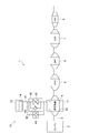
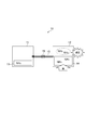
- FIG. 1 It is a schematic block diagram which shows the exhaust gas purification system provided with 1st Embodiment of the chemical heat storage apparatus which concerns on this invention. It is a conceptual diagram which shows operation
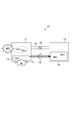
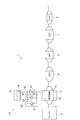
- FIG. 1 is a schematic configuration diagram showing an exhaust purification system provided with a first embodiment of a chemical heat storage device according to the present invention.
- an exhaust purification system 1 is provided in an exhaust system of a diesel engine 2 (hereinafter simply referred to as an engine 2) of a vehicle, and removes harmful substances (environmental pollutants) contained in exhaust gas discharged from the engine 2. It is a purification system.
- the exhaust purification system 1 includes a heat exchanger 4, an oxidation catalyst (DOC: Diesel Oxidation Catalyst) 5, which are arranged in order from an upstream side to a downstream side in an exhaust passage 3 (exhaust system) connected to an engine 2.
- DOC Diesel Oxidation Catalyst
- ASC oxidation catalyst
- the heat exchanger 4 is a device that transfers heat between the exhaust gas from the engine 2 and a reactor 11 described later, and has a honeycomb structure.
- the heat exchanger 4 is not limited to the honeycomb structure, and a known heat exchange structure can be used.
- the oxidation catalyst 5 is a catalyst that oxidizes and purifies HC (hydrocarbon), CO, and the like contained in the exhaust gas.
- the DPF 6 is a filter that collects and removes particulate matter (PM) contained in the exhaust gas.
- the SCR 7 is a catalyst that reduces and purifies NO x contained in the exhaust gas with urea or ammonia (NH 3 ).
- the oxidation catalyst 8 is a catalyst that oxidizes NH 3 that has passed through the SCR 7 and has flowed downstream of the SCR 7.
- the exhaust purification system 1 includes the chemical heat storage device 10 of the present embodiment.
- the chemical heat storage device 10 is a device that normally stores heat (exhaust heat) of exhaust gas and heats the heat exchanger 4 without energy by using exhaust heat when necessary.
- the chemical heat storage device 10 includes a reactor 11 disposed around the heat exchanger 4 and an adsorber 12 disposed away from the heat exchanger 4.
- the reactor 11 includes a heat storage material 13 that generates heat for heating the heat exchanger 4 when it chemically reacts with NH 3 that is a gaseous reaction medium, and desorbs NH 3 by receiving exhaust heat. Yes.
- a material having a composition MX a of a halide is used as the heat storage material 13.
- M is an alkaline earth metal such as Mg, Ca and Sr, or a transition metal such as Cr, Mn, Fe, Co, Ni, Cu and Zn.
- X is a halogen atom such as Cl, Br and I. a is 2 to 3.
- the adsorber 12 includes an adsorbent 14 that can be held and desorbed by physical adsorption of NH 3 .
- adsorbent 14 activated carbon, carbon black, mesoporous carbon, nanocarbon, or the like is used.
- the adsorber 12 can store NH 3 by physically adsorbing NH 3 on the adsorbent 14.
- the reactor 11 and the adsorber 12 are connected via a main pipe 15.
- the main pipe 15 is provided with an electromagnetic valve 16 that is an open / close valve that opens and closes a flow path between the reactor 11 and the adsorber 12.
- the solenoid valve 16 is controlled by a controller (not shown).
- a bypass pipe 17 (bypass passage) is connected to the main pipe 15.
- a mechanical safety valve 18 is provided in the bypass pipe 17 in parallel with the electromagnetic valve 16.
- the safety valve 18 is a separate unit from the solenoid valve 16.
- the safety valve 18 is a valve (first valve) that is mechanically opened when the pressure in the reactor 11 reaches the valve opening set pressure (first valve open set pressure).
- the valve opening set pressure is preset by a spring (not shown) provided on the safety valve 18.
- the safety valve 18 has a check valve function for stopping the flow of NH 3 from the adsorber 12 to the reactor 11. Therefore, when the pressure in the reactor 11 reaches the valve opening set pressure, the safety valve 18 is opened to move NH 3 from the reactor 11 to the adsorber 12, but the pressure in the adsorber 12 is set to the valve opening set pressure. However, NH 3 does not move from the adsorber 12 to the reactor 11.
- the safety valve 18 constitutes a communication means for communicating the reactor 11 and the adsorber 12 when the internal pressure of at least one of the reactor 11 and the adsorber 12 exceeds a predetermined value.
- the solenoid valve 16 is closed during the recovery of NH 3 , and the safety valve 18 operates even when the pressure in the reactor 11 suddenly increases. Abnormal overpressure can be prevented. Therefore, since it is not necessary to make the reactor 11 more robust than necessary so as not to rupture the reactor 11, an increase in the size and weight of the reactor 11 can be suppressed, and the cost can be reduced.
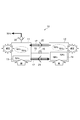
- FIG. 3 is a schematic configuration diagram showing an exhaust purification system provided with a second embodiment of the chemical heat storage device according to the present invention.
- the chemical heat storage device 10 of the present embodiment includes a safety valve unit 20 instead of the safety valve 18 in the first embodiment.
- the safety valve unit 20 includes a mechanical safety valve 21 (first valve) and a mechanical safety valve 22 (second valve) provided in parallel to the safety valve 21.
- the safety valve 21 is a valve (first valve) that mechanically opens when the pressure in the reactor 11 reaches the valve opening set pressure for the reactor (first valve open set pressure).
- the valve opening set pressure for the reactor is preset by a spring (not shown) provided in the safety valve 21.
- the safety valve 21 has a check valve function for stopping the flow of NH 3 from the adsorber 12 to the reactor 11.
- the safety valve 22 is a valve (second valve) that is mechanically opened when the pressure in the adsorber 12 reaches the adsorber valve opening setting pressure (second valve opening setting pressure).
- the adsorber valve opening set pressure is preset by a spring (not shown) provided in the safety valve 22.
- the safety valve 22 has a check valve function for stopping the flow of NH 3 from the reactor 11 to the adsorber 12.
- the pressure in the adsorber 12 is higher than the pressure in the reactor 11.
- the valve opening set pressure for the adsorber of the safety valve 22 is set higher than the valve opening set pressure for the reactor of the safety valve 21.
- the safety valves 21 and 22 constitute communication means for communicating the reactor 11 and the adsorber 12 when the internal pressure of at least one of the reactor 11 and the adsorber 12 exceeds a predetermined value.
- the electromagnetic valve 16 is closed as described above, so that the reactor 11 is filled with high-temperature NH 3 gas as shown in FIG.
- the pressure in 11 rises rapidly.
- the safety valve 21 opens, so that NH 3 in the reactor 11 moves to the adsorber 12 through the bypass pipe 17. become. Thereby, the inside of the reactor 11 is not abnormally overpressured.
- the reactor 11 does not have to be more robust than necessary so as not to rupture the reactor 11, and the adsorber 12 does not need to be more robust than necessary so as not to rupture the adsorber 12. .
- the increase in the physique and weight of the reactor 11 and the adsorber 12 can be suppressed, and further cost reduction can be achieved.
- the adsorber valve opening set pressure of the safety valve 22 is higher than the reactor valve opening set pressure of the safety valve 21. For this reason, even if the pressure in the adsorber 12 becomes high, the safety valve 22 does not open immediately, and malfunction of movement of NH 3 from the adsorber 12 to the reactor 11 can be suppressed. Further, since the valve opening setting pressure for the reactor of the safety valve 21 is lower than the valve opening setting pressure for the adsorber of the safety valve 22, the movement of NH 3 from the reactor 11 to the adsorber 12 is easily performed. 3 can be promoted.
- FIG. 5 is a schematic configuration diagram showing an exhaust purification system including a third embodiment of the chemical heat storage device according to the present invention.
- the chemical heat storage device 10 of the present embodiment includes a relief valve 30 in addition to the configuration of the second embodiment.
- the relief valve 30 is provided in a pipe 31 that connects the reactor 11 and the exhaust passage 3.
- One end of the pipe 31 is connected to an exhaust pipe 32 that connects the heat exchanger 4 and the oxidation catalyst 5 in the exhaust passage 3.
- the relief valve 30 is a valve that mechanically opens when the pressure in the reactor 11 reaches the relief set value.
- the relief set value is set in advance by a spring (not shown) provided in the relief valve 30.
- the relief set value is set higher than the valve opening set pressure for the reactor of the safety valve 21.
- the relief valve 30 has a check valve function for stopping the flow of gas from the exhaust pipe 32 to the reactor 11.
- the relief valve 30 operates to discharge the exhaust pipe from the reactor 11. NH 3 is released to 32. For this reason, it is possible to prevent the reactor 11 and the adsorber 12 from being excessively pressurized.
- NH 3 in the reactor 11 is discharged to the exhaust pipe 32 upstream of the oxidation catalyst 5, but the NH 3 release destination is not limited to the exhaust pipe 32, It may be a pre-exhaust pipe of any one of the exchanger 4, the diesel exhaust particulate removal filter 6, the selective reduction catalyst 7 and the oxidation catalyst 8.
- the relief valve 30 that opens when the pressure in the reactor 11 reaches the relief set value is provided between the reactor 11 and the exhaust passage 3, but the pressure in the adsorber 12 is A relief valve that opens when the relief set value is reached may be provided between the adsorber 12 and the exhaust passage 3, or a relief valve that opens when the pressure in the reactor 11 or the adsorber 12 reaches the relief set value.
- a passage connecting the reactor 11 and the adsorber 12 may be provided.
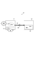
- FIG. 7 is a schematic configuration diagram showing an exhaust gas purification system provided with a fourth embodiment of the chemical heat storage device according to the present invention.
- the chemical heat storage device 10 of this embodiment includes a solenoid valve unit 40 instead of the solenoid valve 16 and the safety valve 18 in the first embodiment.
- the electromagnetic valve unit 40 includes a check valve 42 with respect to the electromagnetic valve 41 as an on-off valve that is a main part.
- the solenoid valve 41 and the check valve 42 constitute one unit. That is, the solenoid valve unit 40 is a solenoid valve 41 with a check valve 42.
- the solenoid valve unit 40 is controlled by a controller (not shown).
- the electromagnetic valve 41 is a valve that opens and closes the flow path between the reactor 11 and the adsorber 12.
- the check valve 42 opens mechanically and stops NH 3 from flowing from the adsorber 12 to the reactor 11. It is a valve (first valve).
- the valve opening set pressure is preset by a spring (not shown) provided in the electromagnetic valve unit 40.
- the check valve 42 constitutes communication means for communicating the reactor 11 and the adsorber 12 when the internal pressure of at least one of the reactor 11 and the adsorber 12 becomes a predetermined value or more.
- the solenoid valve unit 40 When the engine 2 is stopped during the recovery of NH 3, the solenoid valve unit 40 is closed by the operation of the solenoid valve 41. Then, as shown in FIG. 8, the reactor 11 is filled with high-temperature NH 3 gas, and the pressure in the reactor 11 rapidly increases. At this time, when the pressure in the reactor 11 reaches the valve opening set pressure of the solenoid valve unit 40, the solenoid valve unit 40 is opened by the operation of the check valve 42, so that NH 3 in the reactor 11 passes through the main pipe 15. It moves to the adsorber 12 through. Thereby, the overpressure state in the reactor 11 can be relieved.
- FIG. 9 is a schematic configuration diagram showing an exhaust purification system including a fifth embodiment of the chemical heat storage device according to the present invention.
- the chemical heat storage device 10 of the present embodiment is provided with a mechanical safety valve 45 in addition to the configuration of the fourth embodiment.
- the safety valve 45 is provided in parallel to the solenoid valve unit 40 in a bypass pipe 46 (bypass passage) connected to the main pipe 15.
- the safety valve 45 is a valve (second valve) that is mechanically opened when the pressure in the adsorber 12 reaches the adsorber valve opening setting pressure (second valve opening setting pressure).
- the adsorber valve opening set pressure is preset by a spring (not shown) provided in the safety valve 45.
- the adsorber valve opening setting pressure of the safety valve 45 is set higher than the valve opening setting pressure (first valve opening setting pressure) of the electromagnetic valve unit 40.
- the safety valve 45 has a check valve function for stopping the flow of NH 3 from the reactor 11 to the adsorber 12.
- the check valve 42 and the safety valve 45 constitute communication means for communicating the reactor 11 and the adsorber 12 when the internal pressure of at least one of the reactor 11 and the adsorber 12 exceeds a predetermined value. .
- the electromagnetic valve unit 40 When the engine 2 is stopped and the heat is applied to the adsorber 12 due to an increase in the outside air temperature and the adsorber 12 is in a high temperature state, the electromagnetic valve unit 40 is closed. For this reason, as shown in FIG. 10, the pressure in the adsorber 12 rapidly increases due to the high-temperature NH 3 gas in the adsorber 12. At this time, when the pressure in the adsorber 12 reaches the adsorber valve opening set pressure of the safety valve 45, the safety valve 45 opens, so that NH 3 in the adsorber 12 moves to the reactor 11 through the bypass pipe 46. become. Thereby, the overpressure state in the adsorber 12 can be relieved.
- FIG. 11 is a schematic configuration diagram showing an exhaust purification system including a sixth embodiment of the chemical heat storage device according to the present invention.
- the chemical heat storage device 10 of the present embodiment has the main pipe 15 and the electromagnetic valve 16 in the first embodiment, but does not have the bypass pipe 17 and the safety valve 18.
- the chemical heat storage device 10 includes a pressure sensor 50 (detection means) for detecting the pressure in the adsorber 12 and a controller 51 (control means) connected to the pressure sensor 50.
- the controller 51 controls the electromagnetic valve 16 based on the detection value of the pressure sensor 50.
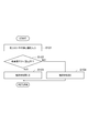
- FIG. 12 is a flowchart showing details of the electromagnetic valve control processing procedure executed by the controller 51. This process is executed in a period other than during the exothermic reaction and the regeneration reaction. Note that the solenoid valve 16 is in a closed state during periods other than during the exothermic reaction and during the regeneration reaction.
- the detection value of the pressure sensor 50 is input (procedure S101), and it is determined whether or not the pressure in the adsorber 12 (adsorber pressure) detected by the pressure sensor 50 is lower than the set pressure (procedure). S102).
- the set pressure is set in advance by experiments or the like.
- step S103 When the pressure in the adsorber 12 is lower than the set pressure, the solenoid valve 16 is controlled to close (step S103), and the process returns to step S101.
- step S104 When the pressure in the adsorber 12 is equal to or higher than the set pressure, the solenoid valve 16 is controlled to open (step S104), and the process returns to step S101.
- the pressure sensor 50 and the controller 51 constitute communication means for communicating the reactor 11 and the adsorber 12 when the internal pressure of at least one of the reactor 11 and the adsorber 12 exceeds a predetermined value.
- the electromagnetic valve 16 is closed during periods other than during the exothermic reaction and during the regeneration reaction. Therefore, when the adsorber 12 heat is given to the adsorber 12 by the rise of outside temperature becomes a high temperature condition, as shown in FIG. 13, the pressure within the adsorber 12 by NH 3 gas having a high temperature within the adsorber 12 Rises rapidly. At this time, when the pressure in the adsorber 12 reaches the set pressure, the electromagnetic valve 16 is opened, so that NH 3 in the adsorber 12 moves to the reactor 11 through the main pipe 15. Thereby, the inside of the adsorber 12 is not abnormally overpressured. Therefore, as in the second embodiment, since the rigidity of the adsorber 12 does not need to be increased more than necessary, an increase in the size and weight of the adsorber 12 can be suppressed.
- the solenoid valve 16 is controlled to open when the pressure in the adsorber 12 is equal to or higher than the set pressure.
- the present invention is not limited to this, and a pressure sensor that detects the pressure in the reactor 11 is used.
- the electromagnetic valve 16 may be controlled to open when the pressure in the reactor 11 becomes equal to or higher than the set pressure.
- the relief valve 30 in the third embodiment may be separately provided.
- any one of the safety valve 18, the safety valve 21, and the check valve 42 which is the first valve that mechanically opens when the pressure in the reactor 11 reaches the first valve opening set pressure.
- the first valve that opens when the pressure in the reactor 11 reaches the first valve opening set pressure is not provided, and the first valve that opens when the pressure in the adsorber 12 reaches the second valve opening set pressure is provided. It is good also as a structure which provides 2 valves.
- the second valve opening set pressure of the second valve is set higher than the first valve opening set pressure of the first valve.
- the second valve opening set pressure of the second valve may be equal to the first valve opening set pressure of the first valve.
- NH 3 is used as a gaseous reaction medium that chemically reacts with the heat storage material 13 of the reactor 11, but the reaction medium is not particularly limited to NH 3 , and CO 2 or the like is used. Also good.
- the heat storage material 13 that chemically reacts with CO 2 includes MgO, CaO, BaO, Ca (OH) 2 , Mg (OH) 2 , Fe (OH) 2 , and Fe (OH). 3 , FeO, Fe 2 O 3 and Fe 3 O 4 can be used.
- the reactor 11 is arrange
- the adsorber 12 includes the adsorbent 14 that physically adsorbs NH 3.
- the adsorber 12 is not limited to this, and may include an adsorbent that chemically adsorbs NH 3. Good.
- the said embodiment heats the heat exchanger 4 provided in the exhaust system of the diesel engine 2
- this invention is the other part (oxidation catalyst 5 provided in the exhaust system of the diesel engine 2).
- Etc. can also be applied.
- the present invention can also be applied to one that heats a catalyst or the like provided in an exhaust system of a gasoline engine, or one that heats an object to be heated other than the engine exhaust system.
Landscapes
- Engineering & Computer Science (AREA)
- Chemical & Material Sciences (AREA)
- General Engineering & Computer Science (AREA)
- Mechanical Engineering (AREA)
- Chemical Kinetics & Catalysis (AREA)
- Combustion & Propulsion (AREA)
- Health & Medical Sciences (AREA)
- Toxicology (AREA)
- Physics & Mathematics (AREA)
- Thermal Sciences (AREA)
- General Chemical & Material Sciences (AREA)
- Materials Engineering (AREA)
- Exhaust Gas After Treatment (AREA)
Abstract
化学蓄熱装置10は、熱交換器4の周囲に配置され、NH3と化学反応すると熱を発生すると共に排熱を受けてNH3を脱離する蓄熱材13を含む反応器11と、NH3の物理吸着による保持及び脱離が可能な吸着材14を含む吸着器12と、反応器11と吸着器12との間に設けられ、両者間の流路を開閉する電磁弁16と、反応器11と吸着器12との間に電磁弁16に対して並列に設けられ、反応器11内の圧力が予め設定された開弁設定圧に達すると、機械的に開く安全弁18とを備えている。安全弁18は、吸着器12から反応器11にNH3が流れるのを止める逆止弁機能を有している。
Description
本発明は、例えばエンジンの排気系等に設けられた加熱対象物を加熱する化学蓄熱装置に関するものである。
従来の化学蓄熱装置としては、例えば特許文献1に記載されているように、エンジン要素部品を加熱する無回収式加熱装置が知られている。特許文献1に記載の化学蓄熱装置は、化学反応媒体としてのアンモニア(NH3)の固定化及び脱離が可能なアンモニア吸着材を有するアンモニア吸着器と、このアンモニア吸着器と配管を介して接続され、NH3との化学反応により発熱すると共に熱源からの余剰熱によりNH3を脱離する化学蓄熱材を有する化学蓄熱反応器と、配管に設けられた開閉弁とを備えている。
エンジンの始動時には、開閉弁を開放することで、アンモニア吸着器のアンモニア吸着材から脱離したNH3が配管を通じて化学蓄熱反応器に供給される。そして、NH3と化学蓄熱材との化学反応によって化学蓄熱材が発熱し、その熱によりエンジン要素部品が加熱される。エンジンの暖機後には、エンジン要素部品の余剰熱によって化学蓄熱材からNH3が脱離する。そして、そのNH3が配管を通じてアンモニア吸着材に再び固定(回収)される。その後、開閉弁が閉止される。
しかしながら、上記従来技術においては、以下の問題点が存在する。即ち、NH3の回収時には、化学蓄熱反応器(以下、単に反応器)が高温状態となるが、その状態でエンジンを停止させると、開閉弁が電磁弁である場合には開閉弁が閉じられる。そのような状態では、反応器からアンモニア吸着器(以下、単に吸着器)にNH3を戻せないため、反応器内にNH3が充満し、反応器内が異常な過圧状態となる。このとき、反応器を破裂させないようにするには、反応器の剛性を十分高くする必要があり、反応器の体格及び重量が必要以上に増大してしまう。
また、反応器の化学蓄熱材を高温で発熱させるためには、数気圧以上の圧力が必要となる。このため、吸着器としては、その圧力に耐え得る剛性が必要となる。ところで、吸着器内の圧力は、外気温によって変動する。具体的には、外気温が高くなると、吸着器の温度が高くなり、吸着器内の圧力が高くなる。ここで、開閉弁が閉じている際には、外気温が上昇して吸着器が高温状態になっても、吸着器から反応器にNH3が移動できないため、吸着器内にNH3が充満し、吸着器内が異常な過圧状態となる。従って、外気温の変動を考慮して吸着器の設計を行う場合には、吸着器の剛性を十分高くする必要があり、吸着器の体格及び重量が必要以上に増大してしまう。
本発明の目的は、反応器または吸着器の内部が異常な過圧状態となることを防止できる化学蓄熱装置を提供することである。
本発明は、加熱対象物を加熱する化学蓄熱装置において、気体の反応媒体と化学反応すると熱を発生する蓄熱材を有する反応器と、反応媒体を吸着する吸着材を有する吸着器と、反応器と吸着器との間に設けられ、反応器と吸着器との間の流路を開閉する開閉弁と、反応器及び吸着器の少なくとも一方の内部圧力が所定値以上になると、反応器と吸着器とを連通する連通手段とを備える。
このような本発明の化学蓄熱装置においては、反応器と吸着器との間に設けられた開閉弁が閉じている状態でも、反応器及び吸着器の少なくとも一方の内部圧力が所定値以上になると、反応器と吸着器とが連通するので、反応器と吸着器との間で反応媒体が移動するようになる。これにより、反応器または吸着器の内部が異常な過圧状態となることを防止できる。
連通手段は、反応器と吸着器との間に設けられ、反応器の内部圧力が予め設定された第1開弁設定圧に達すると開く第1弁及び吸着器の内部圧力が予め設定された第2開弁設定圧に達すると開く第2弁の少なくとも一方を有していてもよい。このような構成では、反応器の内部圧力が第1弁の第1開弁設定圧に達すると、第1弁が開き、反応器から吸着器に反応媒体が移動するようになる。また、吸着器の内部圧力が第2弁の第2開弁設定圧に達すると、第2弁が開き、吸着器から反応器に反応媒体が移動するようになる。これにより、反応器または吸着器の内部圧力を検出するセンサを用いなくても、反応器または吸着器の内部が異常な過圧状態となることを確実に防止できる。
このとき、第1弁は、吸着器から反応器への反応媒体の流れを止める逆止弁機能を含み、第2弁は、反応器から吸着器への反応媒体の流れを止める逆止弁機能を含んでいてもよい。この場合には、吸着器の内部圧力が第1弁の第1開弁設定圧に達しても、吸着器から反応器へ反応媒体が移動することが無い。また、反応器の内部圧力が第2弁の第2開弁設定圧に達しても、反応器から吸着器へ反応媒体が移動することが無い。
また、反応器と吸着器との間には、第1弁及び第2弁が設けられており、第2開弁設定圧は、第1開弁設定圧よりも大きくてもよい。この場合には、吸着器の内部圧力が比較的高い通常状態時に、第2弁が開いて吸着器から反応器に反応媒体が移動してしまうことが抑制される。
さらに、第1弁及び第2弁の何れか一方は、開閉弁と1つのユニットを構成していてもよい。この場合には、使用する弁ユニットの数が必要最小限で済むため、コスト的に有利となる。
また、連通手段は、開閉弁と並列に設けられたバイパス通路を更に有し、第1弁及び第2弁の少なくとも一方は、バイパス通路に設けられていてもよい。この場合には、開閉弁、第1弁及び第2弁の構造が簡単になる。
また、連通手段は、反応器及び吸着器の少なくとも一方の内部圧力を検出する検出手段と、検出手段により反応器及び吸着器の少なくとも一方の内部圧力が所定値以上であることが検出されると、開閉弁を開くように制御する制御手段とを有していてもよい。このような構成では、反応器の内部圧力が所定値以上になると、開閉弁が開き、反応器から吸着器に反応媒体が移動するようになる。また、吸着器の内部圧力が所定値以上になると、開閉弁が開き、吸着器から反応器に反応媒体が移動するようになる。これにより、使用する弁の数を必要最小限としつつ、反応器または吸着器の内部が異常な過圧状態となることを確実に防止できる。
さらに、化学蓄熱装置は、反応器及び吸着器の少なくとも一方の内部圧力が予め決められたリリーフ設定値に達すると開くリリーフ弁を更に備えていてもよい。この場合には、反応器及び吸着器の少なくとも一方の内部圧力が連通手段では対応できないほど高くなったときでも、反応器及び吸着器の少なくとも一方の内部圧力がリリーフ設定値に達すると、リリーフ弁が開き、反応器及び吸着器の少なくとも一方から反応媒体が排出されるようになる。これにより、反応器または吸着器の内部が異常な過圧状態となることを一層防止できる。
このとき、加熱対象物は、エンジンの排気系に設けられており、リリーフ弁は、反応器及び吸着器の少なくとも一方と排気系との間に設けられていてもよい。この場合には、反応器及び吸着器の少なくとも一方の内部圧力がリリーフ設定値に達すると、リリーフ弁が開き、反応器及び吸着器の少なくとも一方から排気系に反応媒体が排出されることになる。
本発明によれば、反応器または吸着器の内部が異常な過圧状態となることを防止できる。これにより、反応器または吸着器を破裂させないように、反応器または吸着器の体格及び重量を必要以上に大きくしなくて済み、コストダウンを図ることが可能となる。
以下、本発明に係る化学蓄熱装置の好適な実施形態について、図面を参照して詳細に説明する。なお、図面において、同一または同等の要素には同じ符号を付し、重複する説明を省略する。
図1は、本発明に係る化学蓄熱装置の第1実施形態を備えた排気浄化システムを示す概略構成図である。同図において、排気浄化システム1は、車両のディーゼルエンジン2(以下、単にエンジン2という)の排気系に設けられ、エンジン2から排出される排気ガス中に含まれる有害物質(環境汚染物質)を浄化するシステムである。
排気浄化システム1は、エンジン2と接続された排気通路3(排気系)の途中に上流側から下流側に向けて順に配置された熱交換器4、酸化触媒(DOC:Diesel Oxidation Catalyst)5、ディーゼル排気微粒子除去フィルタ(DPF:Diesel Particulate Filter)6、選択還元触媒(SCR:Selective Catalytic Reduction)7及び酸化触媒(ASC:Ammonia Slip Catalyst)8を備えている。
熱交換器4は、エンジン2からの排気ガスと後述する反応器11との間で熱の伝達を行う機器であり、ハニカム構造をなしている。なお、熱交換器4はハニカム構造に限らず、周知の熱交換構造を利用可能である。酸化触媒5は、排気ガス中に含まれるHC(炭化水素)及びCO等を酸化して浄化する触媒である。DPF6は、排気ガス中に含まれる粒子状物質(PM:Particulate Matter)を捕集して取り除くフィルタである。SCR7は、尿素またはアンモニア(NH3)によって、排気ガス中に含まれるNOxを還元して浄化する触媒である。酸化触媒8は、SCR7をすり抜けてSCR7の下流側に流れたNH3を酸化する触媒である。
また、排気浄化システム1は、本実施形態の化学蓄熱装置10を備えている。化学蓄熱装置10は、通常は排気ガスの熱(排熱)を蓄えておき、必要なときに排熱を使用することにより、エネルギーレスで熱交換器4を加熱する装置である。化学蓄熱装置10は、熱交換器4の周囲に配置された反応器11と、熱交換器4から離間して配置された吸着器12とを備えている。
反応器11は、気体の反応媒体であるNH3と化学反応すると、熱交換器4を加熱するための熱を発生すると共に、排熱を受けてNH3を脱離する蓄熱材13を含んでいる。蓄熱材13としては、ハロゲン化物のMXaという組成を持つ材料が用いられる。ここで、Mは、Mg、Ca及びSr等のアルカリ土類金属、または、Cr、Mn、Fe、Co、Ni、Cu及びZn等の遷移金属である。Xは、Cl、Br及びI等のハロゲン原子である。aは、2~3である。
吸着器12は、NH3の物理吸着による保持及び脱離が可能な吸着材14を含んでいる。吸着材14としては、活性炭、カーボンブラック、メソポーラスカーボン及びナノカーボン等が用いられる。吸着器12には、NH3を吸着材14に物理吸着させることで、NH3を貯蔵することができる。
反応器11及び吸着器12は、主配管15を介して接続されている。主配管15には、反応器11と吸着器12との間の流路を開閉する開閉弁である電磁弁16が設けられている。電磁弁16は、コントローラ(図示せず)により制御される。
主配管15には、バイパス配管17(バイパス通路)が接続されている。バイパス配管17には、機械式の安全弁18が電磁弁16に対して並列に設けられている。安全弁18は、電磁弁16と別のユニットである。安全弁18は、反応器11内の圧力が開弁設定圧(第1開弁設定圧)に達すると、機械的に開くバルブ(第1弁)である。開弁設定圧は、安全弁18に設けられたバネ(図示せず)により予め設定されている。
安全弁18は、吸着器12から反応器11にNH3が流れるのを止める逆止弁機能を有している。従って、反応器11内の圧力が開弁設定圧に達すると、安全弁18が開くことで、反応器11から吸着器12にNH3が移動するが、吸着器12内の圧力が開弁設定圧に達しても、吸着器12から反応器11にNH3が移動することは無い。
ここで、安全弁18は、反応器11及び吸着器12の少なくとも一方の内部圧力が所定値以上になると、反応器11と吸着器12とを連通する連通手段を構成している。
このような化学蓄熱装置10において、エンジン2からの排気ガスの温度が低いときは、電磁弁16が開くことで、吸着器12から反応器11にNH3が主配管15を介して供給される。反応器11の蓄熱材13(例えばMgBr2)とNH3とが化学反応して化学吸着(配位結合)すると、蓄熱材13から熱が発生する。つまり、下記の反応式(A)における左辺から右辺への反応(発熱反応)が起こる。そして、反応器11で発生した熱によって熱交換器4が加熱される。
MgBr2+xNH3 ⇔ Mg(NH3)xBr2+熱 …(A)
一方、エンジン2からの排気ガスの温度が高くなると、排熱が反応器11の蓄熱材13に与えられることで、蓄熱材13とNH3とが分離する。つまり、上記の反応式(A)における右辺から左辺への反応(再生反応)が起こる。そして、蓄熱材13から脱離したNH3は、主配管15を介して吸着器12に戻り、吸着器12の吸着材14に物理吸着(回収)される。
ここで、排熱によるNH3の回収中にエンジン2を停止させると、電磁弁16に電気が供給されなくなるため、電磁弁16が閉じる。すると、図2に示すように、反応器11内に高温のNH3ガスが充満し、反応器11内の圧力が急激に上昇する。このとき、反応器11内の圧力が安全弁18の開弁設定圧に達すると、安全弁18が開くため、反応器11内のNH3がバイパス配管17を通って吸着器12に移動するようになる。これにより、反応器11内が異常に過圧されることは無い。
このように本実施形態によれば、NH3の回収中に電磁弁16が閉じることで、反応器11内の圧力が急激に上昇しても、安全弁18が動作するので、反応器11内が異常に過圧されることを防止できる。従って、反応器11を破裂させないように反応器11を必要以上に頑丈な構造としなくて済むため、反応器11の体格及び重量の増大を抑制し、コストダウンを図ることができる。
図3は、本発明に係る化学蓄熱装置の第2実施形態を備えた排気浄化システムを示す概略構成図である。同図において、本実施形態の化学蓄熱装置10は、上記第1実施形態における安全弁18に代えて、安全弁ユニット20を備えている。安全弁ユニット20は、機械式の安全弁21(第1弁)と、この安全弁21に対して並列に設けられた機械式の安全弁22(第2弁)とを有している。
安全弁21は、反応器11内の圧力が反応器用開弁設定圧(第1開弁設定圧)に達すると、機械的に開くバルブ(第1弁)である。反応器用開弁設定圧は、安全弁21に設けられたバネ(図示せず)により予め設定されている。安全弁21は、吸着器12から反応器11にNH3が流れるのを止める逆止弁機能を有している。
安全弁22は、吸着器12内の圧力が吸着器用開弁設定圧(第2開弁設定圧)に達すると、機械的に開くバルブ(第2弁)である。吸着器用開弁設定圧は、安全弁22に設けられたバネ(図示せず)により予め設定されている。安全弁22は、反応器11から吸着器12にNH3が流れるのを止める逆止弁機能を有している。
通常状態では、吸着器12内の圧力が反応器11内の圧力よりも高くなる。このため、安全弁22の吸着器用開弁設定圧は、安全弁21の反応器用開弁設定圧よりも高く設定されている。
ここで、安全弁21,22は、反応器11及び吸着器12の少なくとも一方の内部圧力が所定値以上になると、反応器11と吸着器12とを連通する連通手段を構成している。
NH3の回収中にエンジン2を停止させると、上述したように電磁弁16が閉じるため、図4(a)に示すように、反応器11内に高温のNH3ガスが充満し、反応器11内の圧力が急激に上昇する。このとき、反応器11内の圧力が安全弁21の反応器用開弁設定圧に達すると、安全弁21が開くため、反応器11内のNH3がバイパス配管17を通って吸着器12に移動するようになる。これにより、反応器11内が異常に過圧されることは無い。
エンジン2の停止時に、外気温の上昇により吸着器12に熱が与えられて吸着器12が高温状態になると、電磁弁16が閉じている。このため、図4(b)に示すように、吸着器12内の高温のNH3ガスにより吸着器12内の圧力が急激に上昇する。このとき、吸着器12内の圧力が安全弁22の吸着器用開弁設定圧に達すると、安全弁22が開くため、吸着器12内のNH3がバイパス配管17を通って反応器11に移動するようになる。これにより、吸着器12内が異常に過圧されることは無い。
従って、反応器11を破裂させないように反応器11を必要以上に頑丈な構造としなくて済むことに加え、吸着器12を破裂させないように吸着器12を必要以上に頑丈な構造としなくて済む。このため、反応器11及び吸着器12の体格及び重量の増大を抑制し、更なるコストダウンを図ることができる。
また、安全弁22の吸着器用開弁設定圧が安全弁21の反応器用開弁設定圧よりも高くなっている。このため、吸着器12内の圧力が高くなっても、安全弁22が直ぐに開くことは無く、吸着器12から反応器11へのNH3の移動の誤動作を抑制することができる。また、安全弁21の反応器用開弁設定圧が安全弁22の吸着器用開弁設定圧に比べて低いため、反応器11から吸着器12へのNH3の移動が容易に行われるようになり、NH3の回収を促進することができる。
図5は、本発明に係る化学蓄熱装置の第3実施形態を備えた排気浄化システムを示す概略構成図である。同図において、本実施形態の化学蓄熱装置10は、上記第2実施形態における構成に加えて、リリーフ弁30を備えている。
リリーフ弁30は、反応器11と排気通路3とを接続する配管31に設けられている。配管31の一端は、排気通路3における熱交換器4と酸化触媒5とを繋ぐ排気管32に接続されている。
リリーフ弁30は、反応器11内の圧力がリリーフ設定値に達すると、機械的に開くバルブである。リリーフ設定値は、リリーフ弁30に設けられたバネ(図示せず)により予め設定されている。リリーフ設定値は、安全弁21の反応器用開弁設定圧よりも高く設定されている。リリーフ弁30は、排気管32から反応器11にガスが流れるのを止める逆止弁機能を有している。
エンジン2の停止時に、反応器11及び吸着器12の両方が高温状態になると、電磁弁16が閉じている。このため、図6に示すように、反応器11内及び吸着器12内の高温のNH3ガスにより反応器11内及び吸着器12内の圧力が急激に上昇する。このとき、反応器11内の圧力が安全弁21の反応器用開弁設定圧に達すると、安全弁21が開き、吸着器12内の圧力が安全弁22の吸着器用開弁設定圧に達すると、安全弁22が開く。しかし、反応器11内及び吸着器12内は、NH3ガスにより過圧された状態のままである。
反応器11内の圧力がリリーフ弁30のリリーフ設定圧に達すると、リリーフ弁30が開くため、反応器11内のNH3が配管31を通って酸化触媒5の前段の排気管32に放出されるようになる。そして、排気管32に放出されたNH3は、酸化触媒5によって酸化されてNOxとなる。
このように反応器11内及び吸着器12内の圧力が何れも急激に上昇することで、安全弁21,22では対応できない状態になっても、リリーフ弁30の動作によって反応器11内から排気管32にNH3が放出される。このため、反応器11内及び吸着器12内が異常に過圧されることを防止できる。
なお、本実施形態では、反応器11内のNH3を酸化触媒5の前段の排気管32に放出するようにしたが、NH3の放出先としては、特に排気管32には限られず、熱交換器4、ディーゼル排気微粒子除去フィルタ6、選択還元触媒7及び酸化触媒8の何れかの前段の排気管等であってもよい。
また、本実施形態では、反応器11と排気通路3との間に、反応器11内の圧力がリリーフ設定値に達すると開くリリーフ弁30を設けるようにしたが、吸着器12内の圧力がリリーフ設定値に達すると開くリリーフ弁を、吸着器12と排気通路3との間に設けてもよいし、反応器11内または吸着器12内の圧力がリリーフ設定値に達すると開くリリーフ弁を、反応器11と吸着器12とをつなぐ通路に設けてもよい。
図7は、本発明に係る化学蓄熱装置の第4実施形態を備えた排気浄化システムを示す概略構成図である。同図において、本実施形態の化学蓄熱装置10は、上記第1実施形態における電磁弁16及び安全弁18に代えて、電磁弁ユニット40を備えている。
電磁弁ユニット40は、主要部である開閉弁としての電磁弁41に対して逆止弁42を備えている。電磁弁41及び逆止弁42は、1つのユニットを構成している。つまり、電磁弁ユニット40は、逆止弁42付きの電磁弁41である。電磁弁ユニット40は、コントローラ(図示せず)により制御される。
電磁弁41は、反応器11と吸着器12との間の流路を開閉するバルブである。逆止弁42は、反応器11内の圧力が開弁設定圧(第1開弁設定圧)に達すると、機械的に開くと共に、吸着器12から反応器11にNH3が流れるのを止めるバルブ(第1弁)である。開弁設定圧は、電磁弁ユニット40に設けられたバネ(図示せず)により予め設定されている。
ここで、逆止弁42は、反応器11及び吸着器12の少なくとも一方の内部圧力が所定値以上になると、反応器11と吸着器12とを連通する連通手段を構成している。
NH3の回収中にエンジン2を停止させると、電磁弁41の動作により電磁弁ユニット40が閉じる。すると、図8に示すように、反応器11内に高温のNH3ガスが充満し、反応器11内の圧力が急激に上昇する。このとき、反応器11内の圧力が電磁弁ユニット40の開弁設定圧に達すると、逆止弁42の動作により電磁弁ユニット40が開くため、反応器11内のNH3が主配管15を通って吸着器12に移動するようになる。これにより、反応器11内の過圧状態を緩和することができる。
図9は、本発明に係る化学蓄熱装置の第5実施形態を備えた排気浄化システムを示す概略構成図である。同図において、本実施形態の化学蓄熱装置10は、上記第4実施形態における構成に加えて、機械式の安全弁45を備えている。
安全弁45は、主配管15に接続されたバイパス配管46(バイパス通路)に電磁弁ユニット40に対して並列に設けられている。安全弁45は、吸着器12内の圧力が吸着器用開弁設定圧(第2開弁設定圧)に達すると、機械的に開くバルブ(第2弁)である。吸着器用開弁設定圧は、安全弁45に設けられたバネ(図示せず)により予め設定されている。安全弁45の吸着器用開弁設定圧は、電磁弁ユニット40の開弁設定圧(第1開弁設定圧)よりも高く設定されている。また、安全弁45は、反応器11から吸着器12にNH3が流れるのを止める逆止弁機能を有している。
ここで、逆止弁42及び安全弁45は、反応器11及び吸着器12の少なくとも一方の内部圧力が所定値以上になると、反応器11と吸着器12とを連通する連通手段を構成している。
エンジン2の停止時に、外気温の上昇により吸着器12に熱が与えられて吸着器12が高温状態になると、電磁弁ユニット40が閉じている。このため、図10に示すように、吸着器12内の高温のNH3ガスにより吸着器12内の圧力が急激に上昇する。このとき、吸着器12内の圧力が安全弁45の吸着器用開弁設定圧に達すると、安全弁45が開くため、吸着器12内のNH3がバイパス配管46を通って反応器11に移動するようになる。これにより、吸着器12内の過圧状態を緩和することができる。
図11は、本発明に係る化学蓄熱装置の第6実施形態を備えた排気浄化システムを示す概略構成図である。同図において、本実施形態の化学蓄熱装置10は、上記第1実施形態における主配管15及び電磁弁16を有しているが、バイパス配管17及び安全弁18を有していない。
化学蓄熱装置10は、吸着器12内の圧力を検出する圧力センサ50(検出手段)と、この圧力センサ50に接続されたコントローラ51(制御手段)とを備えている。コントローラ51は、圧力センサ50の検出値に基づいて電磁弁16を制御する。
図12は、コントローラ51により実行される電磁弁制御処理手順の詳細を示すフローチャートである。本処理は、発熱反応時及び再生反応時以外の期間に実行される。なお、発熱反応時及び再生反応時以外の期間は、電磁弁16は閉じた状態にある。
図12において、まず圧力センサ50の検出値を入力し(手順S101)、圧力センサ50により検出された吸着器12内の圧力(吸着器圧力)が設定圧よりも低いかどうかを判断する(手順S102)。設定圧は、実験等により予め設定されている。
吸着器12内の圧力が設定圧よりも低いときは、電磁弁16を閉じるように制御し(手順S103)、手順S101に戻る。吸着器12内の圧力が設定圧以上であるときは、電磁弁16を開くように制御し(手順S104)、手順S101に戻る。
ここで、圧力センサ50及びコントローラ51は、反応器11及び吸着器12の少なくとも一方の内部圧力が所定値以上になると、反応器11と吸着器12とを連通する連通手段を構成している。
エンジン2が停止していない状態でも、発熱反応時及び再生反応時以外の期間は電磁弁16が閉じている。このため、外気温の上昇により吸着器12に熱が与えられて吸着器12が高温状態になると、図13に示すように、吸着器12内の高温のNH3ガスにより吸着器12内の圧力が急激に上昇する。このとき、吸着器12内の圧力が設定圧に達すると、電磁弁16が開くため、吸着器12内のNH3が主配管15を通って反応器11に移動するようになる。これにより、吸着器12内が異常に過圧されることは無い。従って、上記第2実施形態と同様に、吸着器12の剛性を必要以上に高くしなくて済むため、吸着器12の体格及び重量の増大を抑制することができる。
なお、本実施形態では、吸着器12内の圧力が設定圧以上であるときに、電磁弁16を開くように制御したが、特にそれに限られず、反応器11内の圧力を検出する圧力センサを設け、反応器11内の圧力が設定圧以上になったときに、電磁弁16を開くように制御してもよい。
また、本実施形態においても、上記第3実施形態におけるリリーフ弁30を別途備えていてもよい。
以上、本発明に係る化学蓄熱装置の好適な実施形態について幾つか説明してきたが、本発明は、上記実施形態に限定されるものでは無い。例えば上記第1~第5実施形態では、反応器11内の圧力が第1開弁設定圧に達すると、機械的に開く第1弁である安全弁18、安全弁21及び逆止弁42の何れかが設けられているが、反応器11内の圧力が第1開弁設定圧に達すると開く第1弁は設けずに、吸着器12内の圧力が第2開弁設定圧に達すると開く第2弁を設ける構成としてもよい。
また、上記第2、第3及び第5実施形態では、第2弁の第2開弁設定圧が第1弁の第1開弁設定圧よりも高く設定されているが、特にその形態には限られず、第2弁の第2開弁設定圧を第1弁の第1開弁設定圧と等しくしてもよい。
また、上記実施形態では、反応器11の蓄熱材13と化学反応する気体の反応媒体としてNH3を使用したが、反応媒体としては、特にNH3には限られず、CO2等を使用してもよい。反応媒体としてCO2を使用する場合、CO2と化学反応する蓄熱材13としては、MgO、CaO、BaO、Ca(OH)2、Mg(OH)2、Fe(OH)2、Fe(OH)3、FeO、Fe2O3及びFe3O4等を使用することができる。
さらに、上記実施形態では、熱交換器4の周囲に反応器11が配置されているが、反応器11の配置箇所としては、特にそれには限られず、例えば熱交換器4の中であってもよい。
また、上記実施形態では、吸着器12がNH3を物理吸着する吸着材14を含んでいるが、吸着器12としては特にこれに限られず、NH3を化学吸着する吸着材を含んでいてもよい。
さらに、上記実施形態は、ディーゼルエンジン2の排気系に設けられた熱交換器4を加熱するものであるが、本発明は、ディーゼルエンジン2の排気系に設けられた他の部分(酸化触媒5等)を加熱するものにも適用可能である。また、本発明は、ガソリンエンジンの排気系に設けられた触媒等を加熱するもの、或いはエンジンの排気系以外の加熱対象物を加熱するものにも適用可能である。
4…熱交換器(加熱対象物)、3…排気通路(排気系)、10…化学蓄熱装置、11…反応器、12…吸着器、13…蓄熱材、14…吸着材、16…電磁弁(開閉弁)、17…バイパス配管(バイパス通路)、18…安全弁(第1弁、連通手段)、21…安全弁(第1弁、連通手段)、22…安全弁(第2弁、連通手段)、30…リリーフ弁、41…電磁弁(開閉弁)、42…逆止弁(第1弁、連通手段)、45…安全弁(第2弁、連通手段)、46…バイパス配管(バイパス通路)、50…圧力センサ(検出手段、連通手段)、51…コントローラ(検出手段、連通手段)。
Claims (9)
- 加熱対象物を加熱する化学蓄熱装置において、
気体の反応媒体と化学反応すると熱を発生する蓄熱材を有する反応器と、
前記反応媒体を吸着する吸着材を有する吸着器と、
前記反応器と前記吸着器との間に設けられ、前記反応器と前記吸着器との間の流路を開閉する開閉弁と、
前記反応器及び前記吸着器の少なくとも一方の内部圧力が所定値以上になると、前記反応器と前記吸着器とを連通する連通手段とを備える、化学蓄熱装置。 - 前記連通手段は、前記反応器と前記吸着器との間に設けられ、前記反応器の内部圧力が予め設定された第1開弁設定圧に達すると開く第1弁及び前記吸着器の内部圧力が予め設定された第2開弁設定圧に達すると開く第2弁の少なくとも一方を有する、請求項1記載の化学蓄熱装置。
- 前記第1弁は、前記吸着器から前記反応器への前記反応媒体の流れを止める逆止弁機能を含み、
前記第2弁は、前記反応器から前記吸着器への前記反応媒体の流れを止める逆止弁機能を含む、請求項2記載の化学蓄熱装置。 - 前記反応器と前記吸着器との間には、前記第1弁及び前記第2弁が設けられており、
前記第2開弁設定圧は、前記第1開弁設定圧よりも大きい、請求項2または3記載の化学蓄熱装置。 - 前記第1弁及び前記第2弁の何れか一方は、前記開閉弁と1つのユニットを構成している、請求項2~4の何れか一項記載の化学蓄熱装置。
- 前記連通手段は、前記開閉弁と並列に設けられたバイパス通路を更に有し、
前記第1弁及び前記第2弁の少なくとも一方は、前記バイパス通路に設けられている、請求項2~4の何れか一項記載の化学蓄熱装置。 - 前記連通手段は、前記反応器及び前記吸着器の少なくとも一方の内部圧力を検出する検出手段と、前記検出手段により前記反応器及び前記吸着器の少なくとも一方の内部圧力が前記所定値以上であることが検出されると、前記開閉弁を開くように制御する制御手段とを有する、請求項1記載の化学蓄熱装置。
- 前記反応器及び前記吸着器の少なくとも一方の内部圧力が予め設定されたリリーフ設定値に達すると開くリリーフ弁を更に備える、請求項1~7の何れか一項記載の化学蓄熱装置。
- 前記加熱対象物は、エンジンの排気系に設けられており、
前記リリーフ弁は、前記反応器及び前記吸着器の少なくとも一方と前記排気系との間に設けられている、請求項8記載の化学蓄熱装置。
Priority Applications (2)
| Application Number | Priority Date | Filing Date | Title |
|---|---|---|---|
| EP15745868.8A EP3104108A4 (en) | 2014-02-05 | 2015-01-15 | Chemical thermal storage device |
| US15/112,062 US20160334172A1 (en) | 2014-02-05 | 2015-01-15 | Chemical thermal storage device |
Applications Claiming Priority (4)
| Application Number | Priority Date | Filing Date | Title |
|---|---|---|---|
| JP2014-020363 | 2014-02-05 | ||
| JP2014020363 | 2014-02-05 | ||
| JP2014098848A JP2015165178A (ja) | 2014-02-05 | 2014-05-12 | 化学蓄熱装置 |
| JP2014-098848 | 2014-05-12 |
Publications (1)
| Publication Number | Publication Date |
|---|---|
| WO2015118921A1 true WO2015118921A1 (ja) | 2015-08-13 |
Family
ID=53777729
Family Applications (1)
| Application Number | Title | Priority Date | Filing Date |
|---|---|---|---|
| PCT/JP2015/050953 Ceased WO2015118921A1 (ja) | 2014-02-05 | 2015-01-15 | 化学蓄熱装置 |
Country Status (4)
| Country | Link |
|---|---|
| US (1) | US20160334172A1 (ja) |
| EP (1) | EP3104108A4 (ja) |
| JP (1) | JP2015165178A (ja) |
| WO (1) | WO2015118921A1 (ja) |
Families Citing this family (1)
| Publication number | Priority date | Publication date | Assignee | Title |
|---|---|---|---|---|
| JP2017089971A (ja) * | 2015-11-10 | 2017-05-25 | 株式会社豊田自動織機 | 化学蓄熱装置 |
Citations (6)
| Publication number | Priority date | Publication date | Assignee | Title |
|---|---|---|---|---|
| JPS61175524U (ja) * | 1985-04-22 | 1986-11-01 | ||
| JPS6490994A (en) * | 1987-09-30 | 1989-04-10 | Toshiba Corp | Heat accumulating system |
| JP2001255089A (ja) * | 2000-03-14 | 2001-09-21 | Suzuki Shoko Kk | 包摂水和物を用いた蓄冷方法および蓄冷熱装置 |
| JP2008115795A (ja) * | 2006-11-06 | 2008-05-22 | Nissan Motor Co Ltd | 蓄熱装置 |
| JP2012172900A (ja) * | 2011-02-21 | 2012-09-10 | Toyota Central R&D Labs Inc | 熱輸送装置 |
| JP2013072558A (ja) * | 2011-09-26 | 2013-04-22 | Toyota Central R&D Labs Inc | 熱回収式加熱装置 |
Family Cites Families (4)
| Publication number | Priority date | Publication date | Assignee | Title |
|---|---|---|---|---|
| FR2913454B1 (fr) * | 2007-03-06 | 2009-06-05 | Peugeot Citroen Automobiles Sa | Dispositif de rechauffage des gaz d'echappement d'un moteur, collecteur d'echappement et ligne d'echappement adaptes, et vehicule les comportant. |
| JP5040891B2 (ja) * | 2008-10-29 | 2012-10-03 | 株式会社デンソー | 車両用蓄熱装置 |
| JP2010230268A (ja) * | 2009-03-27 | 2010-10-14 | Toyoda Gosei Co Ltd | ケミカルヒートポンプ装置及びその使用方法 |
| DE102010031852A1 (de) * | 2010-07-22 | 2012-01-26 | J. Eberspächer GmbH & Co. KG | Abgasanlage mit reaktivem Heizsystem |
-
2014
- 2014-05-12 JP JP2014098848A patent/JP2015165178A/ja active Pending
-
2015
- 2015-01-15 US US15/112,062 patent/US20160334172A1/en not_active Abandoned
- 2015-01-15 EP EP15745868.8A patent/EP3104108A4/en not_active Withdrawn
- 2015-01-15 WO PCT/JP2015/050953 patent/WO2015118921A1/ja not_active Ceased
Patent Citations (6)
| Publication number | Priority date | Publication date | Assignee | Title |
|---|---|---|---|---|
| JPS61175524U (ja) * | 1985-04-22 | 1986-11-01 | ||
| JPS6490994A (en) * | 1987-09-30 | 1989-04-10 | Toshiba Corp | Heat accumulating system |
| JP2001255089A (ja) * | 2000-03-14 | 2001-09-21 | Suzuki Shoko Kk | 包摂水和物を用いた蓄冷方法および蓄冷熱装置 |
| JP2008115795A (ja) * | 2006-11-06 | 2008-05-22 | Nissan Motor Co Ltd | 蓄熱装置 |
| JP2012172900A (ja) * | 2011-02-21 | 2012-09-10 | Toyota Central R&D Labs Inc | 熱輸送装置 |
| JP2013072558A (ja) * | 2011-09-26 | 2013-04-22 | Toyota Central R&D Labs Inc | 熱回収式加熱装置 |
Non-Patent Citations (1)
| Title |
|---|
| See also references of EP3104108A4 * |
Also Published As
| Publication number | Publication date |
|---|---|
| US20160334172A1 (en) | 2016-11-17 |
| JP2015165178A (ja) | 2015-09-17 |
| EP3104108A4 (en) | 2017-08-30 |
| EP3104108A1 (en) | 2016-12-14 |
Similar Documents
| Publication | Publication Date | Title |
|---|---|---|
| JP5775503B2 (ja) | 蓄熱装置 | |
| JP5954123B2 (ja) | 排気ガス浄化システム | |
| WO2015118921A1 (ja) | 化学蓄熱装置 | |
| JP6107563B2 (ja) | 化学蓄熱装置 | |
| JP6493338B2 (ja) | 化学蓄熱装置 | |
| JP6131777B2 (ja) | 化学蓄熱装置 | |
| JP2015183635A (ja) | 化学蓄熱装置 | |
| JP6111905B2 (ja) | 化学蓄熱装置 | |
| JP2015121382A (ja) | 化学蓄熱装置 | |
| EP3217133A1 (en) | Chemical heat storage apparatus | |
| JP2014234950A (ja) | 化学蓄熱装置 | |
| JP6424716B2 (ja) | 化学蓄熱装置 | |
| JP6320551B2 (ja) | 化学蓄熱装置 | |
| JP2014152997A (ja) | 化学蓄熱装置 | |
| JP2016044860A (ja) | ガス吸蔵器及び化学蓄熱装置 | |
| JP2016148482A (ja) | 化学蓄熱装置 | |
| WO2016056488A1 (ja) | 化学蓄熱装置 | |
| WO2016163289A1 (ja) | 化学蓄熱装置 | |
| JP2016196988A (ja) | 化学蓄熱装置 | |
| WO2017013907A1 (ja) | 化学蓄熱装置 | |
| JP2015052442A (ja) | 化学蓄熱装置 | |
| JP2017207033A (ja) | 化学蓄熱装置 | |
| JP2016114032A (ja) | 内燃機関の排気浄化装置 | |
| WO2016009916A1 (ja) | 化学蓄熱装置 | |
| WO2017110405A1 (ja) | 化学蓄熱装置 |
Legal Events
| Date | Code | Title | Description |
|---|---|---|---|
| 121 | Ep: the epo has been informed by wipo that ep was designated in this application |
Ref document number: 15745868 Country of ref document: EP Kind code of ref document: A1 |
|
| WWE | Wipo information: entry into national phase |
Ref document number: 15112062 Country of ref document: US |
|
| REEP | Request for entry into the european phase |
Ref document number: 2015745868 Country of ref document: EP |
|
| WWE | Wipo information: entry into national phase |
Ref document number: 2015745868 Country of ref document: EP |
|
| NENP | Non-entry into the national phase |
Ref country code: DE |