WO2015122015A1 - 永久磁石型モータ - Google Patents
永久磁石型モータ Download PDFInfo
- Publication number
- WO2015122015A1 WO2015122015A1 PCT/JP2014/053643 JP2014053643W WO2015122015A1 WO 2015122015 A1 WO2015122015 A1 WO 2015122015A1 JP 2014053643 W JP2014053643 W JP 2014053643W WO 2015122015 A1 WO2015122015 A1 WO 2015122015A1
- Authority
- WO
- WIPO (PCT)
- Prior art keywords
- permanent magnet
- protrusion
- rotor
- motor
- circumferential
- Prior art date
- Legal status (The legal status is an assumption and is not a legal conclusion. Google has not performed a legal analysis and makes no representation as to the accuracy of the status listed.)
- Ceased
Links
Images






Classifications
-
- H—ELECTRICITY
- H02—GENERATION; CONVERSION OR DISTRIBUTION OF ELECTRIC POWER
- H02K—DYNAMO-ELECTRIC MACHINES
- H02K29/00—Motors or generators having non-mechanical commutating devices, e.g. discharge tubes or semiconductor devices
- H02K29/03—Motors or generators having non-mechanical commutating devices, e.g. discharge tubes or semiconductor devices with a magnetic circuit specially adapted for avoiding torque ripples or self-starting problems
-
- H—ELECTRICITY
- H02—GENERATION; CONVERSION OR DISTRIBUTION OF ELECTRIC POWER
- H02K—DYNAMO-ELECTRIC MACHINES
- H02K1/00—Details of the magnetic circuit
- H02K1/06—Details of the magnetic circuit characterised by the shape, form or construction
- H02K1/22—Rotating parts of the magnetic circuit
- H02K1/27—Rotor cores with permanent magnets
- H02K1/2706—Inner rotors
- H02K1/272—Inner rotors the magnetisation axis of the magnets being perpendicular to the rotor axis
- H02K1/274—Inner rotors the magnetisation axis of the magnets being perpendicular to the rotor axis the rotor consisting of two or more circumferentially positioned magnets
- H02K1/2746—Inner rotors the magnetisation axis of the magnets being perpendicular to the rotor axis the rotor consisting of two or more circumferentially positioned magnets the rotor consisting of magnets arranged with the same polarity, e.g. consequent pole type
-
- H—ELECTRICITY
- H02—GENERATION; CONVERSION OR DISTRIBUTION OF ELECTRIC POWER
- H02K—DYNAMO-ELECTRIC MACHINES
- H02K1/00—Details of the magnetic circuit
- H02K1/06—Details of the magnetic circuit characterised by the shape, form or construction
- H02K1/22—Rotating parts of the magnetic circuit
- H02K1/27—Rotor cores with permanent magnets
- H02K1/2706—Inner rotors
- H02K1/272—Inner rotors the magnetisation axis of the magnets being perpendicular to the rotor axis
- H02K1/274—Inner rotors the magnetisation axis of the magnets being perpendicular to the rotor axis the rotor consisting of two or more circumferentially positioned magnets
- H02K1/2753—Inner rotors the magnetisation axis of the magnets being perpendicular to the rotor axis the rotor consisting of two or more circumferentially positioned magnets the rotor consisting of magnets or groups of magnets arranged with alternating polarity
- H02K1/278—Surface mounted magnets; Inset magnets
-
- H—ELECTRICITY
- H02—GENERATION; CONVERSION OR DISTRIBUTION OF ELECTRIC POWER
- H02K—DYNAMO-ELECTRIC MACHINES
- H02K21/00—Synchronous motors having permanent magnets; Synchronous generators having permanent magnets
- H02K21/12—Synchronous motors having permanent magnets; Synchronous generators having permanent magnets with stationary armatures and rotating magnets
- H02K21/14—Synchronous motors having permanent magnets; Synchronous generators having permanent magnets with stationary armatures and rotating magnets with magnets rotating within the armatures
- H02K21/16—Synchronous motors having permanent magnets; Synchronous generators having permanent magnets with stationary armatures and rotating magnets with magnets rotating within the armatures having annular armature cores with salient poles
-
- H—ELECTRICITY
- H02—GENERATION; CONVERSION OR DISTRIBUTION OF ELECTRIC POWER
- H02K—DYNAMO-ELECTRIC MACHINES
- H02K11/00—Structural association of dynamo-electric machines with electric components or with devices for shielding, monitoring or protection
- H02K11/30—Structural association with control circuits or drive circuits
- H02K11/33—Drive circuits, e.g. power electronics
-
- H—ELECTRICITY
- H02—GENERATION; CONVERSION OR DISTRIBUTION OF ELECTRIC POWER
- H02K—DYNAMO-ELECTRIC MACHINES
- H02K2201/00—Specific aspects not provided for in the other groups of this subclass relating to the magnetic circuits
- H02K2201/06—Magnetic cores, or permanent magnets characterised by their skew
-
- H—ELECTRICITY
- H02—GENERATION; CONVERSION OR DISTRIBUTION OF ELECTRIC POWER
- H02K—DYNAMO-ELECTRIC MACHINES
- H02K2213/00—Specific aspects, not otherwise provided for and not covered by codes H02K2201/00 - H02K2211/00
- H02K2213/03—Machines characterised by numerical values, ranges, mathematical expressions or similar information
-
- H—ELECTRICITY
- H02—GENERATION; CONVERSION OR DISTRIBUTION OF ELECTRIC POWER
- H02K—DYNAMO-ELECTRIC MACHINES
- H02K2213/00—Specific aspects, not otherwise provided for and not covered by codes H02K2201/00 - H02K2211/00
- H02K2213/12—Machines characterised by the modularity of some components
-
- H—ELECTRICITY
- H02—GENERATION; CONVERSION OR DISTRIBUTION OF ELECTRIC POWER
- H02K—DYNAMO-ELECTRIC MACHINES
- H02K3/00—Details of windings
- H02K3/04—Windings characterised by the conductor shape, form or construction, e.g. with bar conductors
- H02K3/28—Layout of windings or of connections between windings
Definitions
- the present invention relates to a permanent magnet type motor including a rotor having a permanent magnet fixed to the surface of a rotor core.
- Patent Document 1 a structure for positioning a permanent magnet in a rotor core.
- Patent Document 2 is disclosed as a structure which has a protrusion between the permanent magnets of a rotor core.
- JP 2004-153913 A Japanese Patent Laid-Open No. 2000-236652
- Patent Document 1 it is possible to accurately position the permanent magnet with the rotor core, but a T-shaped locking piece projecting from the permanent magnet attachment surface to the outer diameter side and both side surfaces of the permanent magnet. Therefore, in the structure having a rotor core with a large protrusion as in Patent Document 2, the magnetic flux of the permanent magnet that flows through the stator core and generates torque is not permanently contributing to the torque. Leakage magnetic flux that flows directly from the magnet to the locking piece is generated. Therefore, the motor torque is reduced by the reduced torque, and there is a problem that the motor size must be increased in order to maintain the predetermined motor torque.
- An object of the present invention is to solve such problems, and it is possible to reduce motor vibration noise caused by reducing rotation unevenness, reduce motor torque reduction, and further increase motor physique.
- An object of the present invention is to obtain a permanent magnet type motor that can reduce the amount of the motor.
- a permanent magnet type motor includes an armature winding, a stator composed of a stator core having a slot for receiving the armature winding, and A rotor core that is provided inside the stator with a gap and is formed by sequentially laminating a plurality of thin steel plates in the direction of the axis, and a plurality of laminated cores formed on the surface of the rotor core at intervals in the circumferential direction.
- the rotor core is formed with a protrusion projecting in the radial direction between the adhering surfaces adjacent to each other,
- the protrusion is composed of a second protrusion that is in contact with the circumferential side surface of the permanent magnet, and a first protrusion that is separated from the side surface of the permanent magnet.
- the first protrusion has a total length L1 in the axial direction, and is a height between an extension line of the pasting surface and a parallel line intersecting the extension line and a corner of the first protrusion.
- the protrusion is composed of the second protrusion that is in contact with the circumferential side surface of the permanent magnet, and the first protrusion that is separated from the side surface of the permanent magnet.
- the total length of the first protrusions is L1, and the height between the extension line of the pasting surface and the parallel lines intersecting this extension line and the corners of the first protrusion part. t1
- the total length of the second protrusions in the axial direction is L2
- the height between the extension line and a parallel line intersecting the extension line and the corner of the second protrusion is t2.
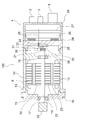
- FIG. 3 is a front sectional view showing a main part of the permanent magnet type motor of FIG. 2.
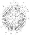
- FIG. 3 is a front sectional view showing the rotor of FIG. 2.
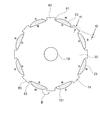
- FIG. 8 is a front sectional view showing a modified example of the rotor of FIG. 7.
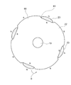
- FIG. 10 is a front sectional view showing another modification of the rotor of FIG. 7.
- FIG. FIG. 1 is an explanatory diagram of an electric power steering apparatus for an automobile in which a permanent magnet type motor 6 (hereinafter abbreviated as a motor) according to Embodiment 1 is incorporated.
- the driver steers a steering wheel (not shown), and the torque is transmitted to the shaft 1 via a steering shaft (not shown).
- the torque detected by the torque sensor 2 is converted into an electric signal and transmitted to an ECU (Electronic Control Unit) 4 through a first connector 3 through a cable (not shown).
- the ECU 4 includes an inverter circuit for driving the control board and the motor 6.
- vehicle information such as vehicle speed is converted into an electric signal and transmitted to the ECU 4 via the second connector 5.
- the ECU 4 calculates necessary assist torque from information on the vehicle such as steering torque and vehicle speed, and supplies current to the motor 6 through the inverter.
- the motor 6 is arranged in a direction parallel to the moving direction indicated by the arrow A of the rack shaft in the housing 7.
- the power supply to the ECU 4 is sent from the battery or alternator via the power connector 8.
- Torque generated by the motor 6 is decelerated by a gear box 9 containing a belt (not shown) and a ball screw (not shown), and a rack shaft (not shown) inside the housing 7 is moved in the direction of arrow A.
- the driving force is generated to assist the driver's steering force.
- the tie rod 10 moves, the tire can steer and the vehicle can be turned.
- the rack boot 11 is provided so that foreign matter does not enter the electric power steering apparatus.
- the motor 6 and the ECU 4 are integrated to constitute an electric drive device 100.
- FIG. 2 is a schematic sectional side view of the electric drive device 100.
- the motor 6 includes a stator core 12 configured by stacking electromagnetic plates, an armature winding 13 housed in the stator core 12, and a frame 14 that fixes the stator core 12. Further, the frame 14 is fixed to the housing 15 on the opposite side of the motor 6 from the ECU 4 with bolts 16.
- the housing 15 is provided with a first bearing 17, and the first bearing 17 supports a shaft 19 together with the second bearing 18 so as to be rotatable.
- the second bearing 18 is supported by a wall portion 36 provided integrally or separately from the frame 14.
- a pulley 20 is press-fitted into one end portion of the shaft 19, that is, the output shaft side, and the pulley 20 functions to transmit a driving force to the belt of the electric power steering apparatus.
- a sensor permanent magnet 21 is provided at the other end of the shaft 19.
- a rotor core 22 is press-fitted into the shaft 19, and a permanent magnet 23 is fixed to the rotor core 22.
- the ECU 4 is provided with a first connector 3 that receives a signal from the torque sensor 2, a second connector 5 that receives vehicle information such as a vehicle speed, and a power supply connector 8 for supplying power.
- the ECU 4 has an inverter circuit for driving the motor 6, and the inverter circuit includes a switching element 24 such as a MOST-FET.
- the switching element 24 may have a configuration in which a bare chip is mounted on a DBC (Direct Bonded Copper) substrate, or a configuration in which a bare chip is molded with a resin. Since the current for driving the motor 6 flows, the switching element 24 generates heat.
- the switching element 24 has a structure for dissipating heat by contacting the heat sink 25 via an adhesive or an insulating sheet.
- the inverter circuit includes a smoothing capacitor, a noise removing coil, a power supply relay, a bus bar for electrically connecting them, and the like, which are omitted in FIG.
- the bus bar is integrally formed with resin to form an intermediate member 26.
- a control board 27 is provided adjacent to the intermediate member 26. Based on the information received from the first connector 3 and the second connector 5, the control board 27 sends a control signal to the switching element 24 in order to appropriately drive the motor 6.
- the control signal is transmitted by a connection member 28 that electrically connects the control board 27 and the switching element 24.
- the connection member 28 is fixed by wire bonding, press fit, solder, or the like.
- the inverter circuit and control board 27 are covered with a case 29.
- the case 29 may be made of resin, may be a metal such as aluminum, or may be a combination of a resin and a metal such as aluminum.
- the control board 27 is disposed along a plane perpendicular to the shaft 19 of the motor 6.
- a sensor unit 30 is arranged on the motor 6 side of the heat sink 25.
- the sensor unit 30 includes a magnetic sensor 31, a substrate 32, a connection member 28, and a support member 33, and the substrate 32 on which the magnetic sensor 31 is mounted is fixed to the heat sink 25 with screws (not shown).
- the magnetic sensor 31 is disposed at a position coaxial with and corresponding to the sensor permanent magnet 21, detects the magnetic field generated by the sensor permanent magnet 21, and knows the direction of the magnetic sensor 31.
- the rotation angle of the rotor 34 of the motor 6 composed of the permanent magnet 21 is detected.
- the ECU 4 supplies an appropriate drive current to the motor 6 according to the rotation angle.
- the connection member 28 is supported by the support member 33 and electrically connects the substrate 32 of the sensor unit 30 and the control substrate 27.
- connection may be press-fit or solder. Since the connecting member 28 needs to penetrate the heat sink 25 and the intermediate member 26, the heat sink 25 and the intermediate member 26 are provided with holes (not shown) through which the connecting member 28 passes. Further, although not shown, the intermediate member 26 is provided with a guide for positioning the connecting member 28.
- FIG. 2 shows an example in which the magnetic sensor 31 is mounted on a board different from the control board 27.
- the magnetic sensor 31 is mounted on the control board 27, and the sensor permanent magnet 21 is passed through the heat sink 25.
- the structure which detects the magnetic flux which leaks may be sufficient.
- positioned contrary to FIG. 2 may be sufficient.
- the magnetic sensor 31 is used as the rotation sensor in FIG. 2, a resolver may be used.
- the heat sink 25 is provided with a recess 35 to increase the distance between the magnetic sensor 31 mounted on the substrate 32 of the sensor unit 30 and the surface of the heat sink 25.
- the heat sink 25 is fixed to the frame 14 of the motor 6 by screws or shrink fitting. In this way, the heat of the heat sink 25 can be transmitted to the frame of the motor 6 by being fixed to the frame 14 of the motor 6.
- FIG. 3 is an electric circuit diagram of the electric power steering apparatus in which the motor 6 according to the first embodiment is incorporated.
- the motor 6 includes a first armature winding 40 including a first U-phase winding U1, a first V-phase winding V1, a first W-phase winding W1, and a second U-phase winding.
- a second armature winding 41 constituted by a line U2, a second V-phase winding V2, and a second W-phase winding W2.
- the Y connection is shown in FIG. 4, a ⁇ connection may be used. In this figure, only the armature winding is shown, and other configurations are omitted.
- the ECU 4 describes only the first inverter 42 and the second inverter 43, and omits other configurations. Three-phase currents are supplied from the respective inverters 42 and 43 to the two armature windings 40 and 41.
- the ECU 4 is supplied with DC power from a power source 44 such as a battery, and is connected to a power relay via a noise removing coil 68.
- the power source 44 is depicted as if inside the ECU 4, but in reality, power is supplied from an external power source 44 such as a battery via the power connector 8.
- the power supply relay includes a first power supply relay 45 and a second power supply relay 46, each of which is composed of two MOST-FETs.
- the power supply relays 45 and 46 are opened so that no excessive current flows.
- the first power supply relay 45 and the second power supply relay 46 are connected in the order of the power supply 44, the coil 68, and the power supply relays 45 and 46, but are closer to the power supply 44 than the coil 68. Needless to say, it may be provided.
- the first capacitor 47 and the second capacitor 48 are smoothing capacitors. In FIG. 3, each capacitor is composed of one capacitor, but it goes without saying that a plurality of capacitors may be connected in parallel.
- the first inverter 42 and the second inverter 43 are each configured by a bridge using six MOST-FETs.
- the first MOST-FET 49 and the second MOST-FET 50 are connected in series.
- a third MOST-FET 51 and a fourth MOST-FET 52 are connected in series, a fifth MOST-FET 53 and a sixth MOST-FET 54 are connected in series, and these three sets of MOST-FETs 49 to 54 are connected in parallel. It is connected.
- one shunt resistor is connected to each of the GND (ground) sides of the lower three second MOST-FETs 50, fourth MOST-FET 52, and third MOST-FET 54, and the first A shunt 55, a second shunt 56, and a third shunt 57 are provided. These shunts 55 to 57 are used for detecting a current value. Although three examples of shunts 55 to 57 are shown, two shunts may be used, and current detection is possible even with one shunt. Needless to say.
- the current is supplied to the motor 6 side from between the first MOST-FET 49 and the second MOST-FET 50 to the U1 phase of the motor 6 through the bus bar or the like.
- the fourth MOST-FET 52 is supplied to the V1 phase of the motor 6 through the bus bar or the like, and the fifth MOST-FET 53 and the sixth MOST-FET 54 are supplied to the W1 phase of the motor 6 through the bus bar or the like.
- the second inverter 43 has the same configuration.
- a first MOST-FET 61 and a second MOST-FET 62 are connected in series, and a third MOST-FET 63 and a fourth MOST-FET 64 are connected.
- a fifth MOST-FET 65 and a sixth MOST-FET 66 are connected in series, and these three sets of MOST-FETs 61 to 66 are connected in parallel.
- one shunt resistor is connected to each of the GND (ground) sides of the lower three second MOST-FETs 62, the fourth MOST-FET 64, and the sixth MOST-FET 66.
- the shunt 58, the second shunt 59, and the third shunt 60 are used. These shunts 58 to 60 are used for detecting a current value. Although three examples of shunts 58 to 60 are shown, two shunts may be used, and current detection is possible even with one shunt. Needless to say.
- the current is supplied to the motor 6 side from between the first MOST-FET 61 and the second MOST-FET 62 to the U2 phase of the motor 6 through the bus bar or the like.
- the fourth MOST-FET 64 is supplied to the V2 phase of the motor 6 through the bus bar or the like, and the fifth MOST-FET 65 and the sixth MOST-FET 66 are supplied to the W2 phase of the motor 6 through the bus bar or the like.
- FIG. 3 does not show a motor relay that electrically cuts off the motor 6 and the inverters 42 and 43 in the event of a failure. However, in order to provide a motor relay, it is provided at the neutral points N1 and N2 and between the motor and the inverter. Can be considered.
- the two inverters 42 and 43 are switched by sending signals to the MOST-FETs 49 to 54 and 61 to 66 from a control circuit (not shown) according to the rotation angle detected by the rotation angle sensor 67 provided in the motor 6. Then, a desired three-phase current is supplied to the first armature winding 40 and the second armature winding 41.
- a rotation angle sensor 67 a GMR sensor, an AMR sensor, a resolver, or the like is used.
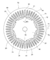
- FIG. 4 is a front sectional view of the main part of the motor 6
- FIG. 5 is a perspective view of the rotor 34
- FIG. 6 is a front sectional view of the rotor 34 in FIG. 4
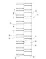
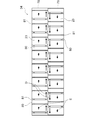
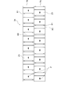
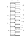
- FIG. 7 is a development view of the rotor 34 in FIG. . 4 and 5 schematically show the protrusion 74, and details of the protrusion 74 are shown in FIG. 6 and FIG. Further, in FIG. 6, the hole portion 76 and the caulking portion 77 formed in the rotor core 22 are omitted.
- a stator 70 including the first armature winding 40, the second armature winding 41, and the stator core 12 surrounds the rotor 34.
- the stator core 12 includes an annular core back 71 made of a magnetic material such as an electromagnetic steel sheet, and teeth 72 extending from the core back 71 inward in the circumferential direction. Armature windings 40 and 41 are housed in slots 73 formed between adjacent teeth 72. Although not shown, insulating paper or the like is inserted between the armature windings 40 and 41 and the stator core 12 to ensure electrical insulation. A total of 48 teeth 72 are formed, and therefore the number of slots 73 is also 48. In each slot 73, four coils of the armature windings 40 and 41 are stored.
- the first armature winding 40 is composed of three phases U1, V1 and W1
- the second armature winding 41 is composed of three phases U2, V2 and W2. Yes.
- Arrangement of the armature windings 40 and 41 is U1, U2, W1, W2, V1, V2 in order from the first slot 73 as shown in FIG. , W2, V1, and V2 are arranged in this order, and are arranged in the same order up to the 48th.
- the armature windings 40 and 41 are arranged so that the current directions of U1 of the first slot 73 and U1 of the seventh slot 73 are opposite to each other.
- the magnetic flux generated by the permanent magnet 23 can be used effectively, and a small and high torque motor 6 can be obtained, and the amount of the permanent magnet 23 can be reduced. As a result, the cost can be reduced compared to a motor having a small winding coefficient.
- a rotor 34 having a permanent magnet 23 on the surface of the rotor core 22 is provided inside the stator 70.
- Eight permanent magnets 23 are arranged in the circumferential direction and have an eight-pole configuration. The polarities of adjacent permanent magnets 23 are opposite to each other.
- the rotor core 22 is provided with a protrusion 74.
- a gap 75 for reducing leakage magnetic flux is formed between the protrusion 74 and the permanent magnet 23.
- the protrusion 74 has an effect of reducing the air gap of the motor 6 and increases the inductance. As a result, the flux-weakening control can easily exert an effect, and there is an effect that the torque can be improved during high-speed rotation.
- Holes 76 are formed in the rotor core 22 at equal intervals along the circumferential direction. By providing the hole 76, weight reduction and inertia can be reduced.
- the rotor core 22 is configured by laminating electromagnetic steel plates and the like, and the electromagnetic steel plates are connected to each other by a caulking portion 77.
- a shaft 19 passes through the center of the rotor core 22.
- the rotor 34 includes a first rotor part 78 and a second rotor part 79 arranged in the axial direction.
- the second rotor part 79 and the first rotor part 78 have the same design and the same axial length. Further, the first rotor portion 78 and the second rotor portion 79 are arranged at positions shifted from each other in the rotation angle direction. This angle is defined as a skew angle ⁇ .
- the protrusion 74 of the rotor core 22 disposed between the N-pole permanent magnet 23 and the S-pole permanent magnet 23 includes a first protrusion 80 and a second protrusion 81. It is configured.
- the first protrusion 80 has a total length in the axial direction of L1, and the height between the extension line of the pasting surface 101 and a parallel line intersecting this extension line and the corner of the first protrusion 80. Is t1.
- the total length of the second protrusion 81 in the axial direction is L2, and the height between the extension line and the parallel line intersecting this extension line and the corner of the second protrusion 81 is t2.
- the relationship between the first protrusion 80 and the second protrusion 81 is (L1 ⁇ t1)> (L2 ⁇ t2), and the first protrusion 80 is larger than the second protrusion 81.
- L1 L2
- t1> t2 is always satisfied, and the height t2 of the second protrusion 81 is set lower than that of the first protrusion 80.
- the permanent magnet 23 is positioned by being brought into contact with one of the pair of second protrusions 81 and is not in contact with the first protrusion 80.
- the outer diameter surface of the rotor 34 is covered with a metal cylinder made of a thin plate such as stainless steel, so that reluctance torque is generated.
- the maximum value of the height t1 of the first protrusion 80 is preferably about the outermost diameter of the permanent magnet 23.
- the motor 6 that can reduce the decrease in the magnet torque and reduce the rotation unevenness caused by the variation in the attaching position on the attaching surface 101 of the permanent magnet 23.
- the effect by embodiment is demonstrated.
- the reluctance torque can be utilized as the size of the first protrusion 80 (L1 ⁇ t1) increases.
- the permanent magnet 23 is affixed to the rotor core 22 with little variation in position on the surface 101 and cannot be accurately fixed, it causes rotational unevenness, and in the electric power steering for a vehicle, the steering feeling deteriorates.
- the permanent magnet 23 may be fixed to the protrusion 74 of the rotor core 22 while being fixed.
- a part of the magnetic flux of the permanent magnet 23 becomes a leakage magnetic flux as shown by an arrow B in FIG. 6 and flows into the protrusion 74, and there is a problem that the magnet torque is reduced accordingly.
- the protrusion 74 is large, so that leakage magnetic flux increases and the magnet torque is likely to decrease. That is, when a gap is provided between the projection 74 and the permanent magnet 23, the decrease in magnet torque can be reduced, but accurate positioning on the attachment surface 101 of the permanent magnet 23 becomes difficult, and the attachment position Variation occurs, and rotation unevenness increases. On the contrary, when the projection 74 and the permanent magnet 23 are brought into contact with each other, rotation unevenness can be reduced, but the leakage magnetic flux from the permanent magnet 23 to the projection 74 is increased, and the magnet torque is reduced.
- the protrusion 74 is positioned on the attachment surface 101 accurately by contacting the first protrusion 80 having a height t1 for utilizing the reluctance torque and the permanent magnet 23.
- the configuration having the second protrusion 81 having a height t2 smaller than the height t1 makes it possible to reduce both a decrease in magnet torque and a reduction in rotation unevenness. The remarkable effect that the motor 6 is realizable is acquired.
- the size of the motor has been increased in order to compensate for the decrease in magnet torque, so that the problem of an increase in raw material costs due to an increase in motor volume and motor weight and an increase in the amount of permanent magnets used has been solved.
- the reduction in the volume of the motor 6 improves the layout by reducing the interference of geometric positions with other in-vehicle devices, and the reduction in the weight of the motor 6 reduces the vehicle weight.
- the reduction in the fuel consumption due to the lightening and the reduction in the amount of use of the permanent magnet 23 have the effect of realizing an improvement in the cost due to a reduction in raw material costs.
- the skew has been described, but it goes without saying that the same effect can be obtained regardless of the presence or absence of the skew.
- the double three-phase winding is described, but it goes without saying that the same effect can be obtained regardless of the number of phases and the number of inverters.
- the motors in which the permanent magnets 23 adjacent to each other in the circumferential direction have different polarities are described. However, as shown in FIG. Needless to say, the same effect can be obtained with a consequent pole type composed of
- the motor 6 composed of the saddle-shaped permanent magnets 23 with the affixing surface 101 being a flat surface has been described.
- the projection 74 including the first projection 80 and the second projection 81 is formed between the adhering surfaces 101 adjacent to the rotor core 22.
- the affixing surface 101 is also a curved surface. Therefore, it is possible to accurately affix a plurality of permanent magnets 23 in the circumferential direction without misalignment. Since it is difficult to compare, the effect of reducing rotation unevenness is particularly remarkable.
- FIG. FIG. 10 is a front sectional view of an essential part of the motor 6 according to the second embodiment.
- the width of the second protrusion 81 against which the permanent magnet 23 abuts in one pole is W3
- the gap distance between the permanent magnet 23 and the stator 70 is tg
- the outer peripheral side of the permanent magnet 23 is arcuate.
- the distance to the stator 70 when viewed from the magnetic flux of the permanent magnet 23, the distance to the stator 70 is shorter than the distance to the first protrusion 80, so that it circulates in the rotor 34 without flowing into the stator 70. Leakage magnetic flux can be reduced.
- FIG. 11 is a development view showing the rotor 34 of the motor 6 according to the third embodiment.
- the width of the second protrusion 81 that contacts the permanent magnet 23 in one pole is W3, and the width that the first rotor 78 and the second rotor 79 are offset by skew.
- W is W
- W3 there is a relationship of W3 ⁇ W.
- Other configurations are the same as those of the motor 6 of the first embodiment.
- FIG. FIG. 12 is a development view showing the rotor 34 of the motor 6 according to the fourth embodiment.
- the adjacent permanent magnets 23 having the same polarity are in contact with the second protrusions 81 in the direction of the repulsive force in the circumferential direction.
- Other configurations are the same as those of the motor 6 of the first embodiment.
- the forces of arrows D acting on each other in the circumferential direction act.
- the direction is the same as the direction of the arrow E in which the permanent magnet 23 is brought into contact with the second protrusion 81 of the protrusion 74 using a jig. Therefore, when the magnetized permanent magnet 23 is brought into contact with the second protrusion 81 and is fixed to the rotor core 22 with an adhesive or the like, the direction of the arrow D in which the permanent magnet 23 repels in the circumferential direction.
- the attaching position of the permanent magnet 23 is not shifted until the adhesive or the like is cured. Further, when the non-magnetized permanent magnet 23 is brought into contact with the second projecting portion 81 and attached to the rotor core 22 and fixed with an adhesive or the like, the arrow that causes the permanent magnet 23 to repel in the circumferential direction. Since the direction of D is the same as the direction naturally contacting the second protrusion 81, even if the fixing force of the adhesive decreases due to temperature rise or aging deterioration, the permanent magnet 23 is naturally Therefore, the attaching position of the permanent magnet 23 is not shifted. That is, even when the fixing force of the adhesive or the like is small, there is a characteristic effect that the accurate positioning of the permanent magnet 23 can be maintained.
- FIG. FIG. 13 is a development view showing the rotor 34 of the motor 6 according to the fifth embodiment.
- the second side where the side surfaces of the permanent magnets 23 are in contact with the same side in the circumferential direction.
- a protrusion 81 is provided.
- Other configurations are the same as those of the motor 6 of the first embodiment.
- the circumferential direction F in contact is the same for the first rotor portion 78 and the second rotor portion 79. Therefore, since the jig or the rotor 34 can be attached while rotating in one direction, the jig can be simplified and the attaching time can be shortened.
- the height of the first protrusion 80 is as large as the height of the permanent magnet 23, the first protrusion 80 is pasted while avoiding collision with every pole. An operation for avoiding the movement of the protrusion 80 in the outer diameter direction is added, which has a special effect on simplification of the jig and shortening of the attaching time.
- FIG. FIG. 14 is a development view showing the rotor 34 of the motor 6 according to the sixth embodiment.
- the protrusion 74 is a plane in which the side surface in the circumferential direction opposite to the second protrusion 81 extends in the axial direction, and is separated from the opposed permanent magnet 23.
- Other configurations are the same as those of the motor 6 of the first embodiment.
- the provision of the second protrusion 81 has an effect of reducing the leakage magnetic flux to the first protrusion 80, and the second protrusions are formed at both ends of the one-pole permanent magnet 26. Therefore, there is an advantage that the permanent magnet 26 can be brought into contact with either the left or right with one punching die.
- the second protrusion 81 is provided only on one side of the protrusion 74 in contact with the permanent magnet 26 and the second protrusion 81 is not provided on the other side, so that the leakage magnetic flux to the protrusion 74 is reduced. By reducing, the decrease in magnet torque can be further reduced.
- the rotor cores 22 of the first rotor part 78 and the second rotor part 79 are made to have the same shape, by turning upside down at the time of press-fitting into the shaft 19, it is possible to add this to the fourth embodiment.
- the embodiment can be easily realized.
- this embodiment can be easily realized in the fifth embodiment by not being turned upside down when the first rotor portion 78 and the second rotor portion 79 are press-fitted into the shaft 19. Needless to say, this embodiment can also be realized in the case of the rotor 34 having no skew between the first rotor portion 78 and the second rotor portion 79.
- FIG. FIG. 15 is a development view showing the rotor 34 of the motor 6 according to the seventh embodiment.
- a notch 80a is formed at the contact portion of each first protrusion 80 that is in contact with each other in the axial direction. Note that only one of the cutout portions 80a may be provided.
- Other configurations are the same as those of the motor 6 of the first embodiment.
- This embodiment has an effect of reducing the axial leakage magnetic flux from the permanent magnet 23 to the first protrusion 80.
- the magnetized magnetic flux becomes a leakage magnetic flux, and the overlapped portion cannot be completely magnetized. Occurrence occurs, and this embodiment has an effect of avoiding this.
- this embodiment is applied to a combination of the embodiment 5 and the embodiment 7, even if the second protrusion 81 is arranged close to the skew boundary portion, the first Since the positions of the notches 80a of the protrusions 80 and the second protrusions 81 do not interfere with each other, they can be easily realized.
- the height t2 of the second protrusion 81 is set to the height of the first protrusion 80. Leakage magnetic flux can be reduced by making it lower than height t1. It is desirable that the second protrusion 81 is provided at two positions with respect to one permanent magnet 23 to reduce the inclination at two points. When the axial length of the permanent magnet 23 is short, This is an effective means when it is desired to make the interval between the protrusions 81 as wide as possible.
- the permanent magnet type motor that is incorporated in the electric power steering device for a vehicle and assists the steering force has been described. However, the electric power steering device is an example and can be applied to other devices. Of course.
Landscapes
- Engineering & Computer Science (AREA)
- Power Engineering (AREA)
- Permanent Field Magnets Of Synchronous Machinery (AREA)
- Power Steering Mechanism (AREA)
- Iron Core Of Rotating Electric Machines (AREA)
- Microelectronics & Electronic Packaging (AREA)
Abstract
Description
また、リラクタンストルクを活用するため、回転子鉄心の永久磁石間に突起を有する構造として下記特許文献2が開示されている。
そのため、減少したトルク分だけモータトルクが低下してしまい、所定のモータトルクを維持するためにはモータ体格を大きくしなければならないという問題点があった。
この固定子の内側に隙間を空けて設けられ、複数の薄板鋼板を軸線の方向に順次積層してなる回転子鉄心、この回転子鉄心の表面に周方向に間隔をおいて複数形成された貼り付け面にそれぞれ貼付された複数の永久磁石、及び前記回転子鉄心の中心軸線にそって貫通したシャフトから構成された回転子と、を備え、
前記回転子鉄心は、隣接した前記貼り付け面間に径方向に突出した突起が形成され、
この突起は、前記永久磁石の前記周方向の側面に当接した第2の突起部と、前記永久磁石の前記側面から離間した第1の突起部とから構成され、
前記第1の突起部は、前記軸線方向の長さの合計をL1、前記貼り付け面の延長線とこの延長線と前記第1の突起部の隅部で交差する平行線との間の高さをt1とし、
前記第2の突起部は、前記軸線方向の長さの合計をL2、前記延長線とこの延長線と前記第2の突起部の隅部で交差する平行線との間の高さをt2としたとき、
(L1×t1)>(L2×t2)である。
前記第1の突起部は、軸線方向の長さの合計をL1、貼り付け面の延長線とこの延長線と前記第1の突起部の隅部で交差する平行線との間の高さをt1とし、
前記第2の突起部は、軸線方向の長さの合計をL2、前記延長線とこの延長線と前記第2の突起部の隅部で交差する平行線との間の高さをt2としたとき、
(L1×t1)>(L2×t2)である。
従って、回転ムラを小さくすることによるモータの振動騒音を低減するとともに、モータトルクの低下を少なくし、さらにはモータ体格の増加を少なくすることができる永久磁石モータを得ることができる。
図1は、実施の形態1の永久磁石型モータ6(以下、モータと略称する。)が組み込まれた、自動車の電動パワーステアリング装置の説明図である。
運転者は、ステアリングホイール(図示せず)を操舵し、そのトルクがステアリングシャフト(図示しない)を介してシャフト1に伝達される。このときトルクセンサ2が検出したトルクは電気信号に変換されケーブル(図示せず)を通じて第1のコネクタ3を介してECU(Elecronic Control Unit)4に伝達される。ECU4は、制御基板とモータ6を駆動するためのインバータ回路を備えている。
一方、車速などの自動車の情報が電気信号に変換され第2のコネクタ5を介してECU4に伝達される。ECU4は、操舵のトルクと車速などの自動車の情報から、必要なアシストトルクを演算し、インバータを通じてモータ6に電流を供給する。
このモータ6は、ハウジング7内のラック軸の矢印Aで示す移動方向に平行な向きに配置されている。また、ECU4への電源供給はバッテリーやオルタネータから電源コネクタ8を介して送られる。
これにより、タイロッド10が動き、タイヤが転舵して車両を旋回させることができる。
モータ6のトルクによってアシストされる結果、運転者は少ない操舵力で車両を旋回させることができる。
なお、ラックブーツ11は、異物が電動パワーステアリング装置内に侵入しないように設けられている。また、モータ6とECU4は一体となっており、電動駆動装置100を構成している。
まず、モータ6について説明する。
モータ6は、電磁板を積層して構成される固定子鉄心12と、固定子鉄心12に納められた電機子巻線13と、固定子鉄心12を固定するフレーム14と、を有する。さらに、フレーム14は、モータ6のECU4と反対側のハウジング15にボルト16によって固定されている。ハウジング15には第1の軸受17が設けられ、この第1の軸受17は、第2の軸受18とともにシャフト19を回転自在に支持している。第2の軸受18は、フレーム14と一体あるいは別体に設けられた壁部36に支持されている。
シャフト19の一端部、即ち出力軸側にはプーリー20が圧入されていて、プーリー20は電動パワーステアリング装置のベルトに駆動力を伝達する働きをする。シャフト19の他端部には、センサ用永久磁石21が設けられている。シャフト19には、回転子鉄心22が圧入されており、回転子鉄心22には、永久磁石23が固定されている。
そこで、スイッチング素子24は、接着剤や絶縁シートなどを介してヒートシンク25と接触させ放熱する構造となっている。インバータ回路には、スイッチング素子24の他に、平滑コンデンサやノイズ除去用コイル、電源リレーやそれらを電気的に接続するバスバーなどがあるが図2では省略している。
磁気センサ31は、センサ用永久磁石21と同軸上でかつ相対応する位置に配置されていて、センサ用永久磁石21の発生する磁界を検出し、その向きを知ることで、回転子鉄心22と永久磁石21とから構成された、モータ6の回転子34の回転角度を検出する。
ECU4は、この回転角度に応じて適切な駆動電流をモータ6に供給する。
さらに、接続部材28は、支持部材33によって支持され、センサ部30の基板32と制御基板27とを電気的に接続している。この接続はプレスフィットでもよいし、はんだでもよい。
なお、接続部材28は、ヒートシンク25及び中間部材26を貫通する必要があるため、ヒートシンク25と中間部材26には接続部材28が通る穴部(図示しない)が設けられている。さらに、図示はしないが、中間部材26は接続部材28を位置決めできるようなガイドが設けられた構成となっている。
また、中間部材26と制御基板27との位置関係が図2と逆に配置された構成でもよい。
ヒートシンク25には、凹部35を設けており、センサ部30の基板32に実装された磁気センサ31とヒートシンク25の表面との間の距離を大きくしている。
ヒートシンク25は、ネジや焼き嵌めなどによってモータ6のフレーム14に固定される。このようにモータ6のフレーム14に固定されることによってヒートシンク25の熱をモータ6のフレームに伝達させることができる。
モータ6は、第1のU相巻線U1、第1のV相巻線V1、第1のW相巻線W1によって構成される第1の電機子巻線40と、第2のU相巻線U2、第2のV相巻線V2、第2のW相巻線W2によって構成される第2の電機子巻線41と、を有している。図4ではY結線としているがΔ結線でもよい。なお、この図では、電機子巻線のみを記載し、他の構成は省略している。
それぞれのインバータ42,43から2つの電機子巻線40、41に3相の電流を供給する。ECU4にはバッテリーなどの電源44から直流電源が供給されており、ノイズ除去用のコイル68を介して、電源リレーが接続されている。
図3では電源44がECU4の内部にあるかのように描かれているが、実際はバッテリー等の外部の電源44から電源コネクタ8を介して、電力が供給される。電源リレーは、第1の電源リレー45及び第2の電源リレー46があり、それぞれ2個のMOST-FETで構成され故障時などは電源リレー45,46を開放して、過大な電流が流れないようにする。
なお、図3では、第1の電源リレー45、第2の電源リレー46は、電源44、コイル68、電源リレー45,46の順に接続されているが、コイル68よりも電源44に近い位置に設けられてもよいことは言うまでもない。
第1のコンデンサ47、第2のコンデンサ48は、平滑コンデンサである。図3ではそれぞれ、1個のコンデンサで構成されているが、複数のコンデンサを並列に接続されて構成してもよいことは言うまでもない。
さらに、下側の3つの第2のMOST-FET50、第4のMOST-FET52、第3のMOST-FET54のGND(グランド)側にはそれぞれシャント抵抗が1つずつ接続されており、第1のシャント55、第2のシャント56、第3のシャント57としている。これらシャント55~57は、電流値の検出に用いられる。
なお、シャント55~57は3個の例を示したが、2個のシャントであってもよいし、1個のシャントであっても電流検出は可能であるため、そのような構成であってもよいことは言うまでもない。
さらに、下側の3つの第2のMOST-FET62、第4のMOST-FET64及び第6のMOST-FET66のGND(グランド)側にはそれぞれシャント抵抗が1つずつ接続されており、第1のシャント58、第2のシャント59及び第3のシャント60としている。これらシャント58~60は、電流値の検出に用いられる。
なお、シャント58~60は3個の例を示したが、2個のシャントであってもよいし、1個のシャントであっても電流検出は可能であるため、そのような構成であってもよいことは言うまでもない。
なお、回転角度センサ67は、GMRセンサやAMRセンサやレゾルバ等が用いられる。
なお、図4及び図5では、突起74に関して概略を示し、突起74の詳細は、図6及び図7に示す。また、図6では回転子鉄心22に形成された穴部76、カシメ部77は省略されている。
第1の電機子巻線40、第2の電機子巻線41及び固定子鉄心12からなる固定子70は、回転子34を囲っている。
固定子鉄心12は、電磁鋼板などの磁性体で構成される環状のコアバック71とコアバック71から周方向内側に延びるティース72から構成される。隣り合うティース72の間に形成されたスロット73に電機子巻線40,41が納められている。図示しないが、電機子巻線40,41と固定子鉄心12との間には絶縁紙等が挿入され電気的絶縁を確保している。
ティース72は、全部で48個形成されており、従ってスロット73も48個となっている。1つのスロット73には電機子巻線40,41のコイルが4本ずつ納められている。
電機子巻線40,41の配置は、図4に示すように1番面のスロット73から順にU1、U2、W1、W2、V1、V2となっており、7番目以降もU1、U2、W1、W2、V1、V2の順に配置されていて、48番目まで同様の順に配置されている。
但し、1番目のスロット73のU1と7番目のスロット73のU1は電流の向きが互いに逆になるように電機子巻線40,41が配置されている。即ち、1番目のスロット73から7番目のスロット73に巻かれた分布巻の構成となっており、電機子巻線40,41は、計6個のティース72を跨っている。これは電気角180度に相当し、短節巻係数が1となるため、永久磁石23が発生する磁束を有効に利用でき、小型高トルクのモータ6が得られ、永久磁石23の量を少なくできるため、巻線係数が小さいモータに比べて低コスト化が実現できるという効果がある。
回転子鉄心22は、電磁鋼板などを積層して構成されており、電磁鋼板同士はカシメ部77によって互いに連結されている。回転子鉄心22の中央にはシャフト19が貫通している。
第1の突起部80は、軸線方向の長さの合計をL1、貼り付け面101の延長線とこの延長線と第1の突起部80の隅部で交差する平行線との間の高さをt1とする。
第2の突起部81は、軸線方向の長さの合計をL2、延長線とこの延長線と第2の突起部81の隅部で交差する平行線との間の高さをt2とする。
第1の突起部80と第2の突起部81との関係は、(L1×t1)>(L2×t2)であり、第1の突起部80は、第2の突起部81よりも大きい。t1=t2の場合は必ずL1>L2となり、第2の突起部81は、第1の突起部82に比べて、回転軸線方向において局所的に配置される。
また、L1=L2の場合には必ずt1>t2となり、第2の突起部81は、第1の突起部80に比べて、その高さt2は低く設定される。
永久磁石23は、一対の第2の突起部81のうちの一方に当接されることで位置決めされ、第1の突起部80に当接することはない。
マグネットトルクだけでなく回転子鉄心22の突起74によりリラクタンストルクも活用するモータ6においては、第1の突起部80の大きさ(L1×t1)が大きいほど、リラクタンストルクを活用することができる。
しかし、永久磁石23を回転子鉄心22に貼り付け面101での位置のばらつきを少なく正確に固定できないと回転ムラの原因となり、車両用の電動パワーステアリングでは操舵フィーリングの悪化の原因となるほか、電子部品などの実装装置では歩留り悪化の原因となるなどの悪影響が生じる。
そのためには、永久磁石23を回転子鉄心22の突起74に片寄せして固定するとよいが、永久磁石23と突起74が近接するほど、本来、固定子鉄心12に流れてマグネットトルクとなるべき永久磁石23の磁束の一部が、図6の矢印Bに示すように漏れ磁束となって突起74に流れ、その分、マグネットトルクが低下してしまう課題が生じる。
特に、マグネットトルクだけでなく、リラクタンストルクを活用する大きな突起74を有する永久磁石型モータでは、突起74が大きいため、漏れ磁束も多くなり、マグネットトルクの低下が起こりやすい。
即ち、突起74と永久磁石23との間に空隙を設けた場合には、マグネットトルクの低下を少なくできるが、永久磁石23の貼り付け面101での正確な位置決めが困難になり、貼り付け位置のばらつきが生じ、回転ムラが大きくなってしまう。
反対に、突起74と永久磁石23とを当接させた場合には、回転ムラを少なくできるが、永久磁石23から突起74への漏れ磁束が大きくなり、マグネットトルクが低下してしまう。
特に、車両用の電動パワーステアリング装置では、モータ6の体積の減少は他の車載機器との幾何学的な位置の干渉を少なくできることによるレイアウト性の改善、モータ6の重量の減少は車両重量を軽くできることによる燃費の改善、永久磁石23の使用量の減少は原材料費の減少によるコストの改善、をそれぞれ実現できる効果がある。
この実施の形態では2重3相巻線について述べたが、相数やインバータの数に関わらず同様の効果が得られることは言うまでもない。この実施の形態では周方向に隣り合う永久磁石23が互いに極性の異なるモータについて述べたが、図8に示すようにN極のみあるいはS極のみの永久磁石23と、回転子鉄心22の異極とで構成されるコンシクエントポール型でも同様の効果が得られることは言うまでもない。
即ち、この瓦型の永久磁石23の場合、貼り付け面101も曲面となるため、複数個の永久磁石23を周方向に位置ずれなく正確に貼り付けることが蒲鉾型の永久磁石23の場合と比べて難しいため、回転ムラの低減に対する効果が特に顕著である。
図10は、この実施の形態2のモータ6の要部正断面図である。
この実施の形態では、1極において永久磁石23が当接される第2の突起部81の幅をW3、永久磁石23と固定子70との空隙距離をtg、永久磁石23の外周側が円弧状であってその周方向の中心の厚みをtmとすると、tg<(2×W3)<tmなる関係を有している。
図11は、この実施の形態3のモータ6の回転子34を示す展開図である。
この実施の形態では、1極において永久磁石23に当接される第2の突起部81の幅をW3、第1の回転子部78と第2の回転子部79とがスキューによりオフセットする幅をWとすると、W3<Wなる関係を有している。
他の構成は、実施の形態1のモータ6と同じである。
この場合には、永久磁石23の磁束から見ると、永久磁石23が固定される同一の第2の回転子部79の第1の突起部80へ流れる周方向漏れ磁束だけでなく、第1の回転子部78の第1の突起部80へ流れる軸線方向漏れ磁束(矢印C)も大きくなる。
スキューは、回転ムラをキャンセルするように決定されるので、マグネットトルクの低下を小さくするためにΔWをゼロに近い正値にすることが効果的であり、そのためにはW3を大きくすればよいことがわかる。
図12は、この実施の形態4のモータ6の回転子34を示す展開図である。
この実施の形態では、隣接した回転子部78,79では、隣接した同極の永久磁石23同士は、周方向の反発力の向きに、それぞれ第2の突起部81に当接している。
他の構成は、実施の形態1のモータ6と同じである。
従って、着磁した永久磁石23を第2の突起部81に当接させて回転子鉄心22に貼り付け接着剤等で固定する場合には、永久磁石23が周方向に反発する矢印Dの向きは、自然と第2の突起部81に当接する方向と同じであるため、接着剤等の硬化までの間、永久磁石23の貼り付け位置がずれてしまうことがない。
また、未着磁の永久磁石23を第2の突起部81に当接させて回転子鉄心22に貼り付け接着剤等で固定されている場合には、永久磁石23が周方向に反発する矢印Dの向きは、自然と第2の突起部81に当接する方向と同じであるため、温度上昇や経年劣化などで接着剤の固定力が低下しても、永久磁石23は、自然と第2の突起部81に当接されるので、永久磁石23の貼り付け位置がずれてしまうことがない。
即ち、接着剤等の固定力が小さい場合にも、永久磁石23の正確な位置決めを持続できる特徴的な効果を有する。
図13は、この実施の形態5のモータ6の回転子34を示す展開図である。
この実施の形態では、隣接した回転子部78,79の同極の永久磁石23では、矢印Fに示すように、それぞれ周方向の同じ側に、永久磁石23の側面が当接した第2の突起部81が設けられている。
他の構成は、実施の形態1のモータ6と同じである。
特に、第1の突起部80の高さが永久磁石23の高さと同程度まで大きい場合には、第1の突起部80を1極毎に衝突するのを避けながら貼り付けるので、第1の突起部80を外径方向に移動するのを避ける動作が加わり、治具の簡素化や貼り付け時間の短縮に対して、特別の効果を有する。
図14は、この実施の形態6のモータ6の回転子34を示す展開図である。
この実施の形態では、突起74は、第2の突起部81と反対側の周方向の側面が軸線方向に延びた平面であって対向した永久磁石23と離間している。
他の構成は、実施の形態1のモータ6と同じである。
この実施の形態では、永久磁石26と当接する突起74の片側のみに第2の突起部81を設け、他方側には第2の突起部81を設けないことで、突起74への漏れ磁束を低減することで、マグネットトルクの低下をさらに少なくすることができる。
また、第1の回転子部78と第2の回転子部79の回転子鉄心22を同一形状にしても、シャフト19への圧入時に上下逆さまにすることで、実施の形態4のものにこの実施の形態を容易に実現できる。
また、第1の回転子部78及び第2の回転子部79のシャフト19への圧入時に上下逆さまにしないことで、実施の形態5のものにこの実施の形態を容易に実現できる。
なお、第1の回転子部78と第2の回転子部79との間でスキューが無い回転子34の場合にもこの実施の形態を実現できることは言うまでもない。
図15は、この実施の形態7のモータ6の回転子34を示す展開図である。
この実施の形態では、軸線方向において互いに当接したそれぞれの第1の突起部80の当接部位には切欠き部80aが形成されている。
なお、切り欠き部80aは、何れか一方だけでもよい。
他の構成は、実施の形態1のモータ6と同じである。
また、未着磁石を回転子鉄心22に貼り付けて着磁する場合、着磁磁束が漏れ磁束となって、オーバーラップした部分が完全には着磁できないため、マグネットトルクの低下や振動騒音の発生が生じ、この実施の形態ではこれを回避できる効果を有する。
この実施の形態を実施の形態5のものと実施の形態7のものとを合わせた形態に適用した場合には、第2の突起部81がスキュー境界部分に近く配置しても、第1の突起部80の切欠き80aと第2の突起部81の位置は干渉しないため、容易に実現できる。
一方、この実施の形態を実施の形態6のものと実施の形態7のものとを合わせた形態に適用した場合には、第2の突起部81の高さt2を第1の突起部80の高さt1よりも低くすることで、漏れ磁束を低減できる。これらは、第2の突起部81は1個の永久磁石23に対して2か所設けて2点で傾きを低減するのが望ましく、永久磁石23の軸線方向長さが短い場合、第2の突起部81の間隔をできるだけ広く取りたい場合には有効な手段となる。
なお、上記各実施の形態では、車両用の電動パワーステアリング装置に組み込まれ、操舵力をアシストする永久磁石型モータについて説明したが、電動パワーステアリング装置は一例であり、他のものに適用できるのは勿論である。
Claims (9)
- 電機子巻線、この電機子巻線を納めるスロットを有する固定子鉄心から構成された固定子と、
この固定子の内側に隙間を空けて設けられ、複数の薄板鋼板を軸線の方向に順次積層してなる回転子鉄心、この回転子鉄心の表面に周方向に間隔をおいて複数形成された貼り付け面にそれぞれ貼付された複数の永久磁石、及び前記回転子鉄心の中心軸線にそって貫通したシャフトから構成された回転子と、を備え、
前記回転子鉄心は、隣接した前記貼り付け面間に径方向に突出した突起が形成され、
この突起は、前記永久磁石の前記周方向の側面に当接した第2の突起部と、前記永久磁石の前記側面から離間した第1の突起部とから構成され、
前記第1の突起部は、前記軸線方向の長さの合計をL1、前記貼り付け面の延長線とこの延長線と前記第1の突起部の隅部で交差する平行線との間の高さをt1とし、
前記第2の突起部は、前記軸線方向の長さの合計をL2、前記延長線とこの延長線と前記第2の突起部の隅部で交差する平行線との間の高さをt2としたとき、
(L1×t1)>(L2×t2)である永久磁石型モータ。 - 前記第2の突起部の前記周方向の幅をW3、前記永久磁石と前記固定子との前記径方向の空隙距離をtg、前記永久磁石の外周側が円弧状であってその前記周方向の中心の厚みをtmとしたとき、
tg<(2×W3)<tmである請求項1に記載の永久磁石型モータ。 - 前記回転子は、前記軸線に沿って複数段の回転子部が前記周方向にスキューして構成され、
隣接した前記回転子部が回転して前記第1の突起部同士が重なり合うまでの前記周方向の長をWとし、
前記第2の突起部の前記周方向の幅をW3としたとき、
W3<Wである請求項1または2に記載の永久磁石型モータ。 - 隣接した前記回転子部では、隣接した同極の前記永久磁石同士の前記周方向の反発力の向きに、それぞれ前記第2の突起部が設けられている請求項3に記載の永久磁石型モータ。
- 隣接した前記回転子部の同極の前記永久磁石では、それぞれ前記周方向の同じ側に前記第2の突起部が設けられている請求項3に記載の永久磁石型モータ。
- 前記突起は、前記第2の突起部と反対側の前記周方向の側面が前記軸線方向に延びた平面であって対向した前記永久磁石と離間している請求項1~5の何れか1項に記載の永久磁石型モータ。
- 前記軸線方向において互いに当接したそれぞれの前記第1の突起部のうち少なくとも一方の当接部位には切欠き部が形成されている請求項3~6の何れか1項に記載の永久磁石型モータ。
- 前記回転子鉄心には、前記軸線方向に貫通した穴部が前記シャフトの周囲に等分間隔で複数形成されている請求項1~7の何れか1項に記載の永久磁石型モータ。
- 前記永久磁石型モータは、車両用の電動パワーステアリング装置に組み込まれ、操舵力をアシストする請求項1~8の何れか1項に記載の永久磁石型モータ。
Priority Applications (5)
| Application Number | Priority Date | Filing Date | Title |
|---|---|---|---|
| PCT/JP2014/053643 WO2015122015A1 (ja) | 2014-02-17 | 2014-02-17 | 永久磁石型モータ |
| CN201480075651.5A CN106030990B (zh) | 2014-02-17 | 2014-02-17 | 永磁体型电动机 |
| EP14882757.9A EP3109972B1 (en) | 2014-02-17 | 2014-02-17 | Permanent magnet motor |
| JP2015562679A JP6157652B2 (ja) | 2014-02-17 | 2014-02-17 | 永久磁石型モータ |
| US15/104,298 US10177637B2 (en) | 2014-02-17 | 2014-02-17 | Permanent magnet motor |
Applications Claiming Priority (1)
| Application Number | Priority Date | Filing Date | Title |
|---|---|---|---|
| PCT/JP2014/053643 WO2015122015A1 (ja) | 2014-02-17 | 2014-02-17 | 永久磁石型モータ |
Publications (1)
| Publication Number | Publication Date |
|---|---|
| WO2015122015A1 true WO2015122015A1 (ja) | 2015-08-20 |
Family
ID=53799777
Family Applications (1)
| Application Number | Title | Priority Date | Filing Date |
|---|---|---|---|
| PCT/JP2014/053643 Ceased WO2015122015A1 (ja) | 2014-02-17 | 2014-02-17 | 永久磁石型モータ |
Country Status (5)
| Country | Link |
|---|---|
| US (1) | US10177637B2 (ja) |
| EP (1) | EP3109972B1 (ja) |
| JP (1) | JP6157652B2 (ja) |
| CN (1) | CN106030990B (ja) |
| WO (1) | WO2015122015A1 (ja) |
Cited By (5)
| Publication number | Priority date | Publication date | Assignee | Title |
|---|---|---|---|---|
| EP3208912A1 (de) * | 2016-02-19 | 2017-08-23 | Siemens Aktiengesellschaft | Läufer |
| WO2018135405A1 (ja) * | 2017-01-20 | 2018-07-26 | 日本電産株式会社 | ロータ及びそれを用いたモータ |
| JP2018117489A (ja) * | 2017-01-20 | 2018-07-26 | 日本電産株式会社 | ロータ及びそれを用いたモータ |
| CN112789789A (zh) * | 2018-10-01 | 2021-05-11 | Lg伊诺特有限公司 | 电机 |
| KR102939064B1 (ko) * | 2019-08-19 | 2026-03-13 | 엘지이노텍 주식회사 | 모터 |
Families Citing this family (11)
| Publication number | Priority date | Publication date | Assignee | Title |
|---|---|---|---|---|
| WO2017090514A1 (ja) * | 2015-11-27 | 2017-06-01 | 日立オートモティブシステムズエンジニアリング株式会社 | 回転電機および回転電機システム |
| CN106505760A (zh) * | 2016-11-17 | 2017-03-15 | 南京航空航天大学 | 一种转子分段的交替极永磁电机 |
| CN106787310B (zh) * | 2016-11-17 | 2019-02-05 | 南京航空航天大学 | 一种磁场增强型的交替极永磁电机 |
| CN106451854B (zh) * | 2016-11-17 | 2019-03-29 | 南京航空航天大学 | 一种叉指交替极永磁电机 |
| DE102017221030A1 (de) * | 2017-11-24 | 2019-05-29 | Zf Friedrichshafen Ag | Stabilisatoraktor mit einem Permanentmagnetmotor |
| WO2020021693A1 (ja) * | 2018-07-27 | 2020-01-30 | 三菱電機株式会社 | 電動機、圧縮機、及び空気調和機 |
| KR102106294B1 (ko) * | 2018-09-21 | 2020-05-04 | 주식회사 만도 | 자동차 조향장치 |
| CN111697726B (zh) * | 2020-06-24 | 2021-11-05 | 珠海格力节能环保制冷技术研究中心有限公司 | 一种电机的转子及电机 |
| CN111697727B (zh) * | 2020-06-24 | 2025-09-19 | 珠海格力节能环保制冷技术研究中心有限公司 | 一种电机的转子及电机 |
| CN111697725B (zh) * | 2020-06-24 | 2021-11-26 | 珠海格力节能环保制冷技术研究中心有限公司 | 一种电机的转子及电机 |
| US20240429760A1 (en) * | 2021-10-20 | 2024-12-26 | Mitsubishi Electric Corporation | Rotor, rotating electric machine, and electric power steering device |
Citations (8)
| Publication number | Priority date | Publication date | Assignee | Title |
|---|---|---|---|---|
| US20020101126A1 (en) * | 2000-12-04 | 2002-08-01 | Crapo Alan D. | Electric power steering system including a permanent magnet motor |
| JP2004153913A (ja) * | 2002-10-30 | 2004-05-27 | Fuji Electric Fa Components & Systems Co Ltd | 永久磁石モータの回転子 |
| JP2009254103A (ja) * | 2008-04-04 | 2009-10-29 | Mitsubishi Electric Corp | 永久磁石型回転電機およびそれを用いた電動パワーステアリング装置 |
| JP2011120328A (ja) * | 2009-12-01 | 2011-06-16 | Yaskawa Electric Corp | 永久磁石形モータ用のロータ、永久磁石形モータ及びこれらの製造方法 |
| JP2012125076A (ja) * | 2010-12-09 | 2012-06-28 | Hitachi Industrial Equipment Systems Co Ltd | 永久磁石モータ及びその製造方法 |
| JP2013009458A (ja) * | 2011-06-22 | 2013-01-10 | Nidec Sankyo Corp | ロータおよびモータ |
| JP2013066370A (ja) * | 2011-06-21 | 2013-04-11 | Asmo Co Ltd | モータ及びロータの製造方法 |
| JP2013251968A (ja) * | 2012-05-31 | 2013-12-12 | Mitsubishi Electric Corp | 磁石式回転電機の回転子ならびにその製造方法および装置 |
Family Cites Families (10)
| Publication number | Priority date | Publication date | Assignee | Title |
|---|---|---|---|---|
| GB2217924B (en) * | 1988-04-25 | 1992-10-07 | Matsushita Electric Works Ltd | Permanent magnet rotor |
| FR2742936B1 (fr) * | 1995-12-22 | 1998-02-13 | Leroy Somer Moteurs | Machine electrique synchrome a aimants permanents adaptee a fonctionner a puissance constante sur une large plage de vitesse |
| US6078121A (en) * | 1997-02-21 | 2000-06-20 | Emerson Electric Co. | Rotor assembly for a rotating machine |
| GB9903308D0 (en) * | 1999-02-13 | 1999-04-07 | Trw Lucas Varity Electric | Improvements relating to electrical power assisted steering assemblies |
| JP2004032947A (ja) * | 2002-06-27 | 2004-01-29 | Aisin Aw Co Ltd | モータ |
| JP4793677B2 (ja) * | 2005-06-20 | 2011-10-12 | 株式会社安川電機 | 永久磁石形モータ |
| EP2797208B1 (en) * | 2011-12-23 | 2022-08-31 | Mitsubishi Electric Corporation | Permanent magnet motor |
| JP6305394B2 (ja) | 2013-04-09 | 2018-04-04 | 三菱電機株式会社 | 永久磁石型モータ及び電動パワーステアリング装置 |
| US9985507B2 (en) | 2013-04-22 | 2018-05-29 | Mitsubishi Electric Corporation | Permanent magnet type motor |
| FR3027744B1 (fr) * | 2014-10-23 | 2016-12-02 | Mmt Sa | Moteur polyphase presentant une alternance d'aimants permanents et de poles saillants |
-
2014
- 2014-02-17 US US15/104,298 patent/US10177637B2/en active Active
- 2014-02-17 JP JP2015562679A patent/JP6157652B2/ja not_active Expired - Fee Related
- 2014-02-17 CN CN201480075651.5A patent/CN106030990B/zh not_active Expired - Fee Related
- 2014-02-17 EP EP14882757.9A patent/EP3109972B1/en not_active Not-in-force
- 2014-02-17 WO PCT/JP2014/053643 patent/WO2015122015A1/ja not_active Ceased
Patent Citations (8)
| Publication number | Priority date | Publication date | Assignee | Title |
|---|---|---|---|---|
| US20020101126A1 (en) * | 2000-12-04 | 2002-08-01 | Crapo Alan D. | Electric power steering system including a permanent magnet motor |
| JP2004153913A (ja) * | 2002-10-30 | 2004-05-27 | Fuji Electric Fa Components & Systems Co Ltd | 永久磁石モータの回転子 |
| JP2009254103A (ja) * | 2008-04-04 | 2009-10-29 | Mitsubishi Electric Corp | 永久磁石型回転電機およびそれを用いた電動パワーステアリング装置 |
| JP2011120328A (ja) * | 2009-12-01 | 2011-06-16 | Yaskawa Electric Corp | 永久磁石形モータ用のロータ、永久磁石形モータ及びこれらの製造方法 |
| JP2012125076A (ja) * | 2010-12-09 | 2012-06-28 | Hitachi Industrial Equipment Systems Co Ltd | 永久磁石モータ及びその製造方法 |
| JP2013066370A (ja) * | 2011-06-21 | 2013-04-11 | Asmo Co Ltd | モータ及びロータの製造方法 |
| JP2013009458A (ja) * | 2011-06-22 | 2013-01-10 | Nidec Sankyo Corp | ロータおよびモータ |
| JP2013251968A (ja) * | 2012-05-31 | 2013-12-12 | Mitsubishi Electric Corp | 磁石式回転電機の回転子ならびにその製造方法および装置 |
Non-Patent Citations (1)
| Title |
|---|
| See also references of EP3109972A4 * |
Cited By (7)
| Publication number | Priority date | Publication date | Assignee | Title |
|---|---|---|---|---|
| EP3208912A1 (de) * | 2016-02-19 | 2017-08-23 | Siemens Aktiengesellschaft | Läufer |
| WO2018135405A1 (ja) * | 2017-01-20 | 2018-07-26 | 日本電産株式会社 | ロータ及びそれを用いたモータ |
| JP2018117490A (ja) * | 2017-01-20 | 2018-07-26 | 日本電産株式会社 | ロータ及びそれを用いたモータ |
| JP2018117489A (ja) * | 2017-01-20 | 2018-07-26 | 日本電産株式会社 | ロータ及びそれを用いたモータ |
| CN112789789A (zh) * | 2018-10-01 | 2021-05-11 | Lg伊诺特有限公司 | 电机 |
| CN112789789B (zh) * | 2018-10-01 | 2023-12-19 | Lg伊诺特有限公司 | 电机 |
| KR102939064B1 (ko) * | 2019-08-19 | 2026-03-13 | 엘지이노텍 주식회사 | 모터 |
Also Published As
| Publication number | Publication date |
|---|---|
| US20160315528A1 (en) | 2016-10-27 |
| US10177637B2 (en) | 2019-01-08 |
| CN106030990A (zh) | 2016-10-12 |
| CN106030990B (zh) | 2018-10-02 |
| JPWO2015122015A1 (ja) | 2017-03-30 |
| EP3109972B1 (en) | 2018-12-05 |
| JP6157652B2 (ja) | 2017-07-05 |
| EP3109972A4 (en) | 2017-12-06 |
| EP3109972A1 (en) | 2016-12-28 |
Similar Documents
| Publication | Publication Date | Title |
|---|---|---|
| JP6157652B2 (ja) | 永久磁石型モータ | |
| JP6124999B2 (ja) | 電動パワーステアリング用永久磁石型モータ | |
| US10320254B2 (en) | Permanent magnet motor and electric power steering apparatus | |
| CN104704717B (zh) | 电动驱动装置 | |
| JP6388705B2 (ja) | 回転電機の回転子、及びモータ | |
| JP6305394B2 (ja) | 永久磁石型モータ及び電動パワーステアリング装置 | |
| EP3139478B1 (en) | Permanent magnet motor | |
| US7453179B2 (en) | DC brushless motor for electrical power steering and the production method thereof | |
| CN106464039A (zh) | 永磁体式电动机及驱动一体型永磁体式电动机 | |
| JP6282326B2 (ja) | 永久磁石型モータ及び電動パワーステアリング装置 | |
| JP6261776B2 (ja) | 電動駆動装置 |
Legal Events
| Date | Code | Title | Description |
|---|---|---|---|
| 121 | Ep: the epo has been informed by wipo that ep was designated in this application |
Ref document number: 14882757 Country of ref document: EP Kind code of ref document: A1 |
|
| ENP | Entry into the national phase |
Ref document number: 2015562679 Country of ref document: JP Kind code of ref document: A |
|
| WWE | Wipo information: entry into national phase |
Ref document number: 15104298 Country of ref document: US |
|
| REEP | Request for entry into the european phase |
Ref document number: 2014882757 Country of ref document: EP |
|
| WWE | Wipo information: entry into national phase |
Ref document number: 2014882757 Country of ref document: EP |
|
| NENP | Non-entry into the national phase |
Ref country code: DE |