WO2015122232A1 - 制御システム、開発支援装置、制御装置、および制御方法 - Google Patents
制御システム、開発支援装置、制御装置、および制御方法 Download PDFInfo
- Publication number
- WO2015122232A1 WO2015122232A1 PCT/JP2015/050899 JP2015050899W WO2015122232A1 WO 2015122232 A1 WO2015122232 A1 WO 2015122232A1 JP 2015050899 W JP2015050899 W JP 2015050899W WO 2015122232 A1 WO2015122232 A1 WO 2015122232A1
- Authority
- WO
- WIPO (PCT)
- Prior art keywords
- data
- packet
- control
- transmission
- master device
- Prior art date
- Legal status (The legal status is an assumption and is not a legal conclusion. Google has not performed a legal analysis and makes no representation as to the accuracy of the status listed.)
- Ceased
Links
Images





Classifications
-
- H—ELECTRICITY
- H04—ELECTRIC COMMUNICATION TECHNIQUE
- H04L—TRANSMISSION OF DIGITAL INFORMATION, e.g. TELEGRAPHIC COMMUNICATION
- H04L47/00—Traffic control in data switching networks
- H04L47/70—Admission control; Resource allocation
- H04L47/78—Architectures of resource allocation
- H04L47/781—Centralised allocation of resources
-
- H—ELECTRICITY
- H04—ELECTRIC COMMUNICATION TECHNIQUE
- H04L—TRANSMISSION OF DIGITAL INFORMATION, e.g. TELEGRAPHIC COMMUNICATION
- H04L12/00—Data switching networks
- H04L12/28—Data switching networks characterised by path configuration, e.g. LAN [Local Area Networks] or WAN [Wide Area Networks]
- H04L12/40—Bus networks
- H04L12/403—Bus networks with centralised control, e.g. polling
-
- H—ELECTRICITY
- H04—ELECTRIC COMMUNICATION TECHNIQUE
- H04L—TRANSMISSION OF DIGITAL INFORMATION, e.g. TELEGRAPHIC COMMUNICATION
- H04L12/00—Data switching networks
- H04L12/28—Data switching networks characterised by path configuration, e.g. LAN [Local Area Networks] or WAN [Wide Area Networks]
- H04L12/42—Loop networks
- H04L12/423—Loop networks with centralised control, e.g. polling
-
- H—ELECTRICITY
- H04—ELECTRIC COMMUNICATION TECHNIQUE
- H04L—TRANSMISSION OF DIGITAL INFORMATION, e.g. TELEGRAPHIC COMMUNICATION
- H04L47/00—Traffic control in data switching networks
- H04L47/10—Flow control; Congestion control
- H04L47/24—Traffic characterised by specific attributes, e.g. priority or QoS
-
- H—ELECTRICITY
- H04—ELECTRIC COMMUNICATION TECHNIQUE
- H04L—TRANSMISSION OF DIGITAL INFORMATION, e.g. TELEGRAPHIC COMMUNICATION
- H04L47/00—Traffic control in data switching networks
- H04L47/10—Flow control; Congestion control
- H04L47/36—Flow control; Congestion control by determining packet size, e.g. maximum transfer unit [MTU]
-
- H—ELECTRICITY
- H04—ELECTRIC COMMUNICATION TECHNIQUE
- H04L—TRANSMISSION OF DIGITAL INFORMATION, e.g. TELEGRAPHIC COMMUNICATION
- H04L67/00—Network arrangements or protocols for supporting network services or applications
- H04L67/01—Protocols
- H04L67/12—Protocols specially adapted for proprietary or special-purpose networking environments, e.g. medical networks, sensor networks, networks in vehicles or remote metering networks
- H04L67/125—Protocols specially adapted for proprietary or special-purpose networking environments, e.g. medical networks, sensor networks, networks in vehicles or remote metering networks involving control of end-device applications over a network
-
- H—ELECTRICITY
- H04—ELECTRIC COMMUNICATION TECHNIQUE
- H04L—TRANSMISSION OF DIGITAL INFORMATION, e.g. TELEGRAPHIC COMMUNICATION
- H04L7/00—Arrangements for synchronising receiver with transmitter
- H04L7/0091—Transmitter details
-
- G—PHYSICS
- G05—CONTROLLING; REGULATING
- G05B—CONTROL OR REGULATING SYSTEMS IN GENERAL; FUNCTIONAL ELEMENTS OF SUCH SYSTEMS; MONITORING OR TESTING ARRANGEMENTS FOR SUCH SYSTEMS OR ELEMENTS
- G05B2219/00—Program-control systems
- G05B2219/30—Nc systems
- G05B2219/31—From computer integrated manufacturing till monitoring
- G05B2219/31115—Network controller
Definitions
- the present invention relates to a control system for controlling a controlled object, a development support apparatus and a control apparatus directed to the control system, and a control method.
- Machines and equipment used in many production sites are typically controlled by a control system including a programmable controller (hereinafter also referred to as “PLC”).
- PLC programmable controller
- remote devices are arranged at various locations in the field, command values are given to the respective remote devices, and field information is collected from the respective remote devices. Transmission of such command values and field information is performed via a field network.
- Patent Document 1 Japanese Patent Laid-Open No. 2012-094944
- Patent Document 1 In the communication band control device disclosed in the above-mentioned Japanese Patent Application Laid-Open No. 2012-094944 (Patent Document 1), in a one-to-many data transfer between a communication driver and a task, a detailed band designation according to the importance of a transmission request Is realized. On the other hand, in the control system as described above, a network having a predetermined control cycle and band is adopted. For this reason, it is impossible to apply the prior art technical idea of dynamically designating a band for each data.
- the present invention has been made in view of such problems, and in a control system including a master device and a plurality of slave devices connected via a network, transmits data at a cycle suitable for each slave device. It aims at providing the composition which can be performed.
- a control system for controlling a control target includes a master device and a plurality of slave devices connected to the master device via a network.
- the master device transmits a packet to the network every one or a plurality of predetermined control cycles, and each of the plurality of slave devices is configured to sequentially transfer packets from the master device.
- the master device includes execution means for repeatedly executing a program including processing related to input / output in the slave device. When the execution means executes the program, the first data and the second data are calculated.
- the master device sets a first transmission cycle that is an integral multiple of the control cycle for the first data, and a second transmission cycle that is an integral multiple of the control cycle for the second data and is longer than the first transmission cycle.
- the master device stores each of the first data and the second data together with information indicating the destination slave device, and each of the plurality of slave devices includes the data included in the packet from the master device. , Only data destined for its own device is extracted.
- the allocating unit determines to which packet each of the first data and the second data is allocated so as not to exceed a maximum data size allowed for each packet.
- the allocating unit determines a method of allocating to a packet in order from data having a short transmission cycle among a plurality of transmission target data set with a transmission cycle.
- the second data includes a plurality of data elements.
- the assigning means assigns a plurality of data elements included in the second data to the same packet when the second data is set to be transmitted in synchronization with the second data. If the second data is not set to be transmitted synchronously, the second data is assigned to the packet so that a plurality of data elements included in the second data are assigned to the same packet. decide.
- the allocating unit prioritizes data set to be transmitted in synchronization among a plurality of data to be transmitted over other data, and determines how to allocate the packet.
- the assigning means includes means for notifying an occupation state of assigned data in each packet.
- the allocating unit cannot determine how to allocate the first data and the second data according to a predetermined communication parameter including a control period, a first transmission period, and a second transmission period.
- a means for notifying the communication parameter to be changed is included.
- a development support device directed to a control system for controlling a controlled object includes a master device and a plurality of slave devices connected to the master device via a network.
- the master device transmits packets on the network at predetermined control cycles, and each of the plurality of slave devices is configured to sequentially transfer packets from the master device.
- the development support apparatus is configured so that the master device is set to calculate the first data and the second data by repeatedly executing a program including processing related to input / output in the slave device.
- Communication parameters including setting of a first transmission cycle that is an integer multiple of the control cycle for data and setting of a second transmission cycle that is an integer multiple of the control cycle for the second data and is longer than the first transmission cycle
- a control device connected to a plurality of slave devices via a network sends a packet to the network every one or a plurality of predetermined control periods, and a plurality of slave devices Are configured to sequentially transfer packets from the control device.
- the control device includes execution means for repeatedly executing a program including processing related to input / output in the slave device. When the execution means executes the program, the first data and the second data are calculated.
- the control device sets a first transmission cycle that is an integral multiple of the control cycle for the first data, and a second transmission cycle that is an integral multiple of the control cycle for the second data and is longer than the first transmission cycle.
- the control device stores each of the first data and the second data in the packet together with information indicating the slave device of the transmission destination, and each of the plurality of slave devices includes the data included in the packet from the control device. , Only data destined for its own device is extracted.
- a development support device directed to a control system for controlling a controlled object includes a master device and a plurality of slave devices connected to the master device via a network.
- the master device transmits a packet to the network every one or a plurality of predetermined control cycles, and each of the plurality of slave devices is configured to sequentially transfer packets from the master device.
- the master device includes execution means for repeatedly executing a program including processing related to input / output in the slave device, and first data and second data are calculated by the execution means executing the program.
- the development support apparatus sets a first transmission cycle that is an integral multiple of the control cycle for the first data, and a second transmission that is an integral multiple of the control cycle for the second data and is longer than the first transmission cycle.
- the allocation method is determined so that the first data is allocated to the packet every first transmission period and the second data is allocated to the packet every second transmission period.
- a control method in a control system for controlling a controlled object includes a master device and a plurality of slave devices connected to the master device via a network.
- the control method includes a step in which the master device sends a packet to the network every one or more of a predetermined control period, and each of the plurality of slave devices sequentially transfers packets from the master device. Repeatedly executing a program including processing related to input / output in the slave device. First data and second data are calculated by executing the program.
- the control method includes setting a first transmission cycle that is an integral multiple of the control cycle for the first data, and a second transmission cycle that is an integral multiple of the control cycle for the second data and is longer than the first transmission cycle.
- the control system can transmit data at a cycle suitable for each slave device.
- FIG. 8 is a diagram illustrating the total packet occupation time and the occupation ratio in a state where the output information illustrated in FIG. 7C is assigned to the packet. It is a flowchart which shows the process sequence in the PLC system which concerns on this Embodiment. It is a figure which shows the example of a data structure of the packet in the PLC system which concerns on this Embodiment. It is a schematic diagram which shows the whole structure of the PLC system which concerns on the modification of this Embodiment.
- control system a system centered on a PLC will be exemplified.
- PLC the PLC
- various industrial computers can be mainly used.
- a new processing device an Arimetic device
- such a new processing device can also be employed.
- FIG. 1 is a schematic diagram showing an overall configuration of a PLC system 1 according to the present embodiment.
- a PLC system 1 is a control system for controlling a control target, and includes a main processing device 2 and a plurality of remote devices 40_1, 40_2, 40_3,..., 40_N (hereinafter referred to as “remote devices”). 40 ”in some cases.).
- the main processing device 2 and the remote device 40 are control devices that constitute at least a part of the PLC system 1, and are connected via the field network 4.
- Communication via the field network 4 is controlled mainly by the main processing device 2.
- the main processing device 2 transmits data sequentially transmitted over the field network 4 in accordance with a predetermined timing or rule.
- data sequentially transmitted on the field network 4 is also referred to as “packet”.
- the main processing device 2 is referred to as a “master device”
- each of the remote devices 40_1, 40_2, 40_3,..., 40_N is also referred to as a “slave device”.
- the PLC system 1 as a control system includes a main processing device 2 (master device) and a plurality of remote devices 40 (slave devices) connected to the main processing device 2 (master device) via the field network 4. Including.
- the main processing device 2 executes an input signal (hereinafter referred to as “field information”) from a remote device 40 by executing a program (including a user program and a system program as will be described later) necessary for controlling a control target.
- field information an input signal
- a program including a user program and a system program as will be described later
- a process of performing a control calculation based on the collected field information a process of outputting a command value calculated by the control calculation to the remote device 40, and the like.
- the main processing device 2 includes a CPU unit 10, one or more IO units 20, and a power supply unit 30 as its device configuration.
- the CPU unit 10 and the IO unit 20 are connected to each other via an internal bus (not shown) so that data communication is possible.
- the power supply unit 30 supplies power of an appropriate voltage to the CPU unit 10 and the IO unit 20.
- the CPU unit 10 includes an arithmetic unit that executes a program necessary for controlling the control target, and a communication processing unit 110 for controlling communication with the remote device 40 via the field network 4.
- the CPU 10 may be connected to a development support apparatus 500 for installing various programs, debugging, and monitoring the program execution state.
- the development support apparatus 500 is typically realized by executing a support program on a general-purpose computer.
- the support program may include a function that can emulate the CPU unit 10 and execute various programs in a simulated manner.
- the remote device 40 receives field information from an external switch or sensor, and transmits the received field information number to the main processing device 2 via the field network 4. At the same time, the remote device 40 outputs the command value received from the main processing device 2 via the field network 4 to an external relay or actuator. Alternatively, the remote device 40 may operate by itself according to a command value received via the field network 4. For example, as the remote device 40, a simple IO unit having no arithmetic function, an IO unit having an arithmetic function, a device including an actuator such as a servo driver, and the like are assumed.
- FIG. 1 shows a case where the remote device 40 is a servo driver.
- the remote devices 40_1, 40_2, 40_3,..., 40_N include servo motors 42_1, 42_2, 42_3,. , And a corresponding servo motor is controlled through each remote device in response to a command from the main processing device 2.
- the communication processing unit 110 of the CPU unit 10 performs cyclic transmission on the field network 4 of a data string (packet) including data handled by the main processing device 2 (master device) and the plurality of remote devices 40 (slave devices). Is configured to manage. This packet is transmitted every one or a plurality of predetermined control periods. That is, the main processing device 2 (master device) transmits a packet on the field network 4 every one or a plurality of predetermined control periods, and each of the plurality of remote devices 40 (slave devices) performs main processing. It is configured to sequentially transfer packets from the device 2 (master device).
- control cycle means the processing time of a user program, which may be a predetermined constant cycle, or is dynamically changed according to the amount of user programs to be executed, etc. In some cases.
- FIG. 1 schematically shows a so-called ring-type field network, but a daisy chain connection field network may also be used. That is, as the field network according to the present embodiment, any configuration may be adopted as long as the data sequence (packet) can be transmitted every one or a plurality of predetermined control periods.
- FIG. 2 is a schematic diagram showing a device configuration of the CPU unit 10 included in the PLC system 1 according to the present embodiment.
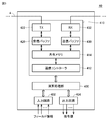
- the CPU unit 10 includes a processor 100 as a calculation unit, a main memory 102, a nonvolatile memory 104, and an internal bus controller 108 in addition to the communication processing unit 110. These components are configured to be capable of data communication with each other via the internal bus 109.
- the processor 100 executes a program related to control.
- the processor 100 reads out a necessary program from the nonvolatile memory 104 or the like and develops it in the main memory 102 for execution.
- the nonvolatile memory 104 stores a user program 105 and a system program 106 as programs related to control. Data relating to execution of the program of the processor 100 is stored in the work area 103 in the main memory 102.
- the internal bus controller 108 is connected to the IO unit 20 via an internal bus (not shown), and mediates exchange of data (field information and command values) between the processor 100 and the IO unit 20.
- the communication processing unit 110 is connected to the remote device 40 via the field network 4 and mediates exchange of data (field information and command value) between the CPU unit 10 and the remote device 40. More specifically, the communication processing unit 110 includes a communication controller 112, a shared memory 114, a transmission buffer 120, a transmission circuit 122, a reception buffer 130, and a reception circuit 132.
- the transmission buffer 120 and the transmission circuit 122 realize processing related to frame transmission from the communication processing unit 110 to the external device, and the reception buffer 130 and the reception circuit 132 perform processing related to frame transmission from the external device to the communication processing unit 110.
- the communication processing unit 110 includes a shared memory 114, and the processor 100 writes the calculated designated value to the shared memory 114 and reads field information from the shared memory 114. That is, the command value written in the shared memory 114 is transferred to the transmission buffer 120 and transmitted from the transmission buffer 120 to the remote device 40. The field information acquired from the remote device 40 is received by the reception buffer 130 and then transferred to the shared memory 114.
- a series of processing in the communication processing unit 110 is executed by the communication controller 112. More specifically, the communication controller 112 generates and transmits a packet in accordance with a command from the processor 100 or the like, and extracts necessary information from the received packet.
- the communication processing unit 110 may realize a part or all of it using software. Alternatively, a part or the whole may be realized by using a hardware circuit such as an ASIC (Application Specific Integrated Circuit) or an FPGA (Field-Programmable Gate Array).
- ASIC Application Specific Integrated Circuit
- FPGA Field-Programmable Gate Array
- FIG. 3 is a schematic diagram illustrating an example of a device configuration of the remote device 40 included in the PLC system 1 according to the present embodiment.
- FIG. 3 shows a configuration example having an arithmetic function and an IO function.
- remote device 40 includes an arithmetic processing unit 400, an input circuit 402, an output circuit 404, and a communication processing unit 410.
- the arithmetic processing unit 400 executes a predetermined process based on a packet transmitted via the field network 4 and transmits a packet obtained as a result of the process via the field network 4.
- the input circuit 402 outputs a signal (field information) input from the field side to the arithmetic processing unit 400.
- the output circuit outputs a signal corresponding to the command value given from the arithmetic processing unit 400 to the field side.
- the communication processing unit 410 is connected to the CPU unit 10 via the field network 4 and mediates exchange of data (field information and command value) between the remote device 40 and the CPU unit 10. More specifically, the communication processing unit 410 includes a communication controller 412, a shared memory 414, a transmission buffer 420, a transmission circuit 422, a reception buffer 430, and a reception circuit 432. These components have the same functions as the communication controller 112, the shared memory 114, the transmission buffer 120, the transmission circuit 122, the reception buffer 130, and the reception circuit 132 (all of which are shown in FIG. 2). The explanation is not repeated. However, the processing when the packet is received by the communication processing unit 410 that is a part of the slave device and the processing when the packet is transmitted are the communication processing unit 110 of the CPU unit 10 that is a part of the master device. It is different from the processing in.
- the remote device 40 (the arithmetic processing unit 400, the input circuit 402, the output circuit 404, and the communication processing unit 410) may realize all or part of its functions using software, but may be an ASIC, FPGA, or the like. It is preferable to implement a part or all of the hardware circuit.
- a method capable of packet transmission that is, capable of real-time communication
- various industrial Ethernet can be used as the field network 4.
- Specific examples of the industrial Ethernet (registered trademark) include, for example, EtherCAT (registered trademark), PROFINET IRT, MECHATROLINK (registered trademark) -III, Powerlink, SERCOS (registered trademark) -III, and CIP Motion.
- a field network other than industrial Ethernet (registered trademark) may be used.
- DeviceNet, CompoNet (registered trademark), or the like may be used.
- FIG. 4 is a diagram for explaining an overview of processing in the PLC system 1 according to the present embodiment.
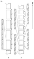
- FIG. 4A is a diagram illustrating a data structure of a packet according to related technology
- FIG. 4B is a diagram illustrating a data structure of a packet according to the present embodiment.
- each packet has the same data structure, and the same type of data set is transmitted every one or a plurality of predetermined control periods.
- each packet includes data directed to each of the slaves 1 to 6.
- the command value for each axis must be stored in each packet, and the data length becomes long. That is, as the number of axes to be controlled increases, the control cycle T1 (that is, the control cycle in the remote device 40) becomes longer in proportion to the number of axes.
- command values are transmitted at the same control cycle as the axis that requires a faster response even for axes that do not have a fast response. There may be constraints on the right axis.
- control cycle is made substantially variable according to the speed request in each remote device 40. That is, in the configuration for controlling the plurality of servo motors 42, a control cycle corresponding to the required response time is set for each axis, and a packet corresponding to the set control cycle is generated. Thereby, each set control cycle is realized.
- each packet includes both command values for slave 1 and slave 2, but the command values for slaves 3 to 6 are included only in one of the two packets. That is, the command values for the slave 3 and the slave 4 are included only in the odd-numbered packets, and the command values for the slave 5 and the slave 6 are included only in the even-numbered packets.
- the slave 1 and the slave 2 can realize the same control cycle as the control cycle T2, and the slaves 3 to 6 can realize a control cycle twice the control cycle T2. That is, in the example shown in FIG. 4B, an axis that requires a high-speed response is communicated at every control cycle T, and an axis that is not so communicates once every plural times, so that packet data per one time is transmitted. Since the size can be reduced and thereby the control cycle can be shortened, a high-speed response can be realized.
- the data structure stored in each packet is dynamically changed for each period in accordance with the number of slave apparatuses in the control system and the control period request in each slave apparatus. By changing it, control that satisfies the requirements is realized.
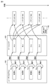
- FIG. 5 is a diagram for explaining packet generation processing included in the PLC system 1 according to the present embodiment.
- the user program 105 includes a plurality of processes A, B, C, and D, and each process is repeatedly executed independently of each other at a predetermined control cycle.
- the transmission periods of the plurality of processes A, B, C, and D are As, Bs, Cs, and Ds, respectively.
- Each of the processes A, B, C, and D uses field information collected from the remote device 40 or the like as an input, and output information A (n), B (n), C (n), D ( n) (where n is an integer of 1 or more).
- output information is defined in an array format. However, the output information is not necessarily stored in an array format, and may be stored in an arbitrary arrangement and format.
- the output information A (n), B (n), C (n), and D (n) are stored in the work area 103 in the main memory 102 and are sequentially updated at the control cycle of the corresponding process. That is, the main processing device 2 (master device) includes a processor 100 (execution means) that repeatedly executes a user program 105 including processing related to input / output in the remote device 40 (slave device). The processor 100 (execution means) calculates a plurality of types of data by executing the user program 105.
- the output information stored in the work area 103 is selected according to a predetermined assignment setting 150, and packets Nt1, Nt2, Nt3, Nt4,.
- the output information A (n) calculated by the process A is assigned to each generated packet. That is, the output information A (n) is transmitted every packet control period.
- the communication frequency (control cycle / transmission cycle) of the output information B (n), C (n), D (n) is set to 1/3 of the output information A (n). That is, the output information B (n), C (n), and D (n) are transmitted at a rate of 1 out of 3 times. In other words, the output information B (n), C (n), and D (n) are updated at a period corresponding to three times the packet control period.
- output information A (n), B (n), C (n), and D (n) calculated by processing included in the user program 105 is transmitted from the main processing device 2 to the plurality of remote devices 40.
- the processing can be similarly applied to processing in which the main processing device 2 collects field information from each remote device 40.
- a command for acquiring field information (hereinafter also referred to as “data refresh command”) is transmitted to the target remote device 40. Therefore, as described above, the data refresh command is transmitted at an appropriate control cycle according to the type of processing and / or necessary field information, so that the communication bandwidth prepared in advance by the field network 4 can be obtained. It can be used effectively to realize data communication that supports high-speed response.
- the process of assigning output information to be transmitted to a packet that is, the process of determining the assignment setting 150 is typically executed by the processor 100 of the CPU unit 10. However, it may be executed in an offline environment such as the development support apparatus 500 connected to the CPU unit 10.
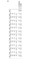
- FIG. 6 is a diagram illustrating an example of communication parameters used in the PLC system 1 according to the present embodiment. Referring to FIG. 6, for example, when a plurality of processes A, B, C, and D are repeatedly executed, the transmission periods As, Bs, Cs, and Ds that are the execution periods of the processes are 250 ⁇ sec, 500 ⁇ sec, and 1000 ⁇ sec, respectively. , 1000 ⁇ sec.
- Processes A, B, C, and D output output information A (n), B (n), C (n), and D (n), respectively.
- the number of data Ac, Bc, Cc, Dc included in each output information is assumed to be 3, 4, 4, 1, respectively. That is, the output information A (n) includes three data elements A (1), A (2), and A (3), and the output information B (n) and C (n) are all four.
- Data elements B (1), B (2), B (3), B (4) and data elements C (1), C (2), C (3), C (4) are respectively included and output Information D (n) consists of one data element D (1).
- the packet occupation times Ap, Bp, Cp, and Dp corresponding to the output information A (n), B (n), C (n), and D (n) are necessary when the corresponding data elements are assigned to the packets. And can vary depending on the length and type of each data element. That is, the packet occupation time means the data size of the corresponding data element, and the control cycle Tc means the maximum data size that can be transmitted per packet.
- the data size of the data element may be used as it is for evaluation. That is, the data size (maximum data size) that can be assigned to each packet is determined first using the control cycle Tc, and the allocation method may be determined using the data size of each data element to be assigned. .
- the packet occupation times Ap and Dp for the output information A (n) and D (n) are both 30 ⁇ sec, and the packet occupation times for the output information B (n) and C (n) Both Bp and Cp are 35 ⁇ sec.
- the control cycle Tc indicates a packet generation cycle.
- the communication frequencies Af, Bf, Cf, and Df for each of the processes A, B, C, and D are values that indicate how much output information corresponding to the packet is assigned based on the control cycle Tc.
- the communication frequency Af for the process A is 0.5, which means that output information A (n) corresponding to one of the packets is copied every time two packets are transmitted.
- the communication frequency Bf for the process B is 0.25, which means that output information B (n) corresponding to one of the packets is copied every time four packets are transmitted.
- the communication frequencies Cf and Df for the processes C and D are both 0.125, and output information C (n) and D (n) corresponding to one of the packets every time eight packets are transmitted. ) To copy each. Therefore, the transmission cycle of the output information A (n) is the control cycle Tc ⁇ 2, the transmission cycle of the output information B (n) is the control cycle Tc ⁇ 4, and the output information C (n) and D (n) It is necessary to assign data elements to packets so that the transmission cycle is the control cycle Tc ⁇ 8.
- the “synchronization” column indicates whether or not the data set in the corresponding output information needs to be transmitted in the same packet.
- “synchronization” is designated as “necessary”, and the data sets in these output information are assigned to the same packet. That is, it is set to transmit data sets in these output information in synchronization.
- “synchronization” is designated as “not necessary”, and some of the data sets in these output information are Data and remaining data are allowed to be assigned to different packets.
- FIG. 7 is a diagram for explaining an example of packet generation processing according to the communication parameters shown in FIG. With reference to FIGS. 7A to 7C, how the assignment setting is determined according to the communication parameters shown in FIG. 6 will be described.
- control cycle / shortest transmission cycle If the highest communication frequency (control cycle / shortest transmission cycle)> 1, the current control cycle cannot satisfy the request, so the transmission cycle, packet occupation time, control cycle, etc. need to be reviewed. .
- the allocation method is preferentially determined for output information having a high communication frequency required (that is, a short transmission cycle required). However, when output information that needs to be synchronized is included, the output information is prioritized.
- the allocation method is determined so as to be allocated at In the example shown in FIG. 6, since the communication frequency of the output information A (n) is 0.5, the output information A (n) is assigned to the packet at a frequency of once every two control cycles Tc. That is, three data elements A (1), A (2), and A (3) included in the output information A (n) are assigned to a single data packet.
- FIG. 7A shows three data elements A (1) included in the output information A (n) in each of odd-numbered packets, that is, packets Nt1, Nt3, Nt5, Nt7, Nt9, Nt11, Nt13,. ), A (2), A (3) are shown as examples.
- the condition of Ac ⁇ control cycle Tc (125 ⁇ sec) is satisfied.
- the allocation method is determined so that the entire data set of the output information D (n) that needs another synchronization is allocated to the reciprocal of the communication frequency Df with one frequency. Since the communication frequency of the output information D (n) is 0.125, the output information D (n) is assigned to the packet with a frequency of once every eight control cycles Tc. In the state shown in FIG. 7 (a), there is still room in the odd-numbered packets, so that one data element D (1) included in the output information D (n) is included in each of the packets Nt1, Nt9,. An example of assignment is shown.
- the main processing device 2 sets the first transmission cycle that is an integral multiple ( ⁇ 2) of the control cycle Tc with respect to the output information A (n) (first data), and the output information.
- output information D (n) (first data) is assigned to one of the packets sent for each control cycle for each first transmission cycle, and for each control cycle Tc1.
- the allocation function performs allocation to the packets in order from the data with the shortest transmission cycle among the plurality of transmission target data set with the transmission cycle.
- output information that does not need to be synchronized is assigned to packets in descending order of communication frequency.
- the allocation method is determined so as to allocate (4).
- the allocation is performed so as to satisfy the two conditions that the allocation frequency becomes a designated value and that the total packet occupation time in each packet does not exceed the control period. That is, the output information B is sequentially assigned so that the occupation ratio (total packet occupation time / control cycle Tc) in each packet does not exceed 1. Since the output information B does not need to be synchronized, it is not necessary to place all data elements in the same packet as long as the requested communication frequency can be secured.
- FIG. 7B shows a state in which all of the data elements B (1), B (2), B (3), and B (4) included in the output information B (n) are assigned.
- the data elements B (1), B (2), B (3) are allocated to the packets Nt2, Nt6, Nt10,.
- data element B (4) is the same packet as data element B (1), B (2), B (3). It cannot be assigned to Nt2. Further, for the odd-numbered packet Nt3, since the total packet occupation time is close to the limit value, the data element B (4) is necessarily assigned to the packet Nt4. Similarly, the data element B (4) is assigned to each of the packets Nt4, Nt8, Nt12,.
- each of the data elements C (1), C (2), C (3), and C (4) included in the output information C (n) is determined.
- each data element may be assigned to a different packet.
- the allocation is performed so as to satisfy the two conditions that the allocation frequency becomes a designated value and that the total packet occupation time in each packet does not exceed the control period. That is, the output information C is sequentially assigned so that the occupation ratio (total packet occupation time / control cycle Tc) in each packet does not exceed 1. Since the output information C does not need to be synchronized, it is not necessary to place all data elements in the same packet as long as the requested communication frequency can be secured.
- the output information C (n) is necessarily assigned to the packet Nt4.
- the packet occupation time Bp ⁇ (data number Bc ⁇ 3) + packet occupation time Cp ⁇ (data number Cc ⁇ 2) 105 ⁇ control.
- the packet occupation time Bp ⁇ (data number Bc ⁇ 3) + packet occupation time Cp ⁇ (data number Cc ⁇ 2) 105 ⁇ control cycle Tc is established.
- FIG. 7C shows a state in which all of the data elements included in the output information A (n), output information B (n), output information C (n), and output information D (n) are assigned.
- the assignment setting 150 (FIG. 5) defines this assignment state.
- FIG. 8 is a diagram showing the total packet occupation time and the occupation ratio in a state where the output information shown in FIG. 7C is assigned to the packet. As shown in FIG. 8, in any packet, the total packet occupation time does not exceed the control cycle Tc (125 ⁇ sec), and as a result, it can be seen that the occupation ratio is less than 1.
- the allocation function is set to transmit in synchronization with the output information, and when the output information includes a plurality of data elements included in the output information. Is assigned to the same packet (ie, a single packet or a common packet).
- the allocation function is not set to transmit in synchronization with the output information and a plurality of data elements included in the output information cannot be allocated to the same packet.
- the allocation method is determined so that the data elements are allocated over a plurality of packets.
- the assignment function assigns the output information, which is set to be transmitted in synchronization among the plurality of pieces of output information to be transmitted, with priority over other data.
- each output information is transmitted at a designated communication frequency, and each output information is appropriately assigned so that conditions such as the total packet occupation time are satisfied.
- FIG. 9 is a flowchart showing a processing procedure in the PLC system 1 according to the present embodiment.
- FIG. 9 exemplarily shows only processing related to data transmission as described above.
- Each step shown in FIG. 9 is typically executed by the processor 100 of the CPU unit 10 of the main processing device 2.
- the development support apparatus 500 the following steps can be executed virtually offline. That is, the development support apparatus 500 has substantially the same function as the CPU unit 10 of the main processing apparatus 2.
- the processor 100 receives the user program 105 and various settings and stores them in the nonvolatile memory 104 (step S2). Subsequently, the processor 100 executes an allocation process (steps S10 to S34 described below) for transmitting output information calculated by each process included in the user program 105 at a designated communication frequency.
- the processor 100 reads out communication parameters (see FIG. 6 and the like) designated by the user and identifies output information to be transmitted (step S10). Subsequently, the processor 100 refers to the read communication parameter and determines whether there is output information that is set to be synchronized among the output information to be transmitted (step S12). If there is output information that is set to require synchronization (YES in step S12), the processor 100 has the highest communication frequency among the output information that is set to need synchronization. High output information is selected (step S14). Then, the processor 100 is selected so as to satisfy the two conditions that the allocated frequency matches the designated communication frequency and that the total packet occupation time in each packet does not exceed the control period. An attempt is made to assign the output information to any packet (step S16). The processor 100 determines whether the assignment of the selected output information to all the packets has been successful (step S18).
- step S18 If all of the selected output information cannot be assigned to the packet (NO in step S18), the specified communication parameter cannot be realized, and the transmission cycle, packet occupation time, control cycle, etc. Is notified to the user (step S32). Then, the process ends.
- step S18 the processor 100 determines that the output information that is set to require synchronization is included. Then, it is determined whether there is a packet that has not been assigned yet (step S20). If there is output information that is set to require synchronization and that has not been assigned to a packet (YES in step S20), output information that has not been assigned to a packet. Among them, output information with the highest communication frequency is selected (step S22). And the processor 100 repeats the process after step S16.
- step S24 all of the output information that is set to need to be synchronized is assigned to the packet (in the case of NO in step S20), or is set to need to be synchronized. If the output information is not present (NO in step S12), the processor 100 determines whether there is output information that has not been assigned to a packet (step S24).
- step S24 If there is output information that has not been assigned to a packet (YES in step S24), the processor 100 outputs the highest communication frequency among the output information that has not been assigned to a packet. Information is selected (step S26). Then, the processor 100 is selected so as to satisfy the two conditions that the allocated frequency matches the designated communication frequency and that the total packet occupation time in each packet does not exceed the control period. An attempt is made to assign the output information to any packet (step S28). The processor 100 determines whether or not the assignment of the selected output information to all the packets has been successful (step S30).
- step S30 If the selected output information has not been successfully assigned to all packets (NO in step S30), the process proceeds to step S32.
- step S30 when all of the selected output information cannot be allocated to the packet (YES in step S30), the processor 100 repeats the processing from step S24.
- processor 100 Eventually, when all of the output information has been assigned to a packet (NO in step S24), processor 100 generates and stores assignment setting 150 indicating the state of assignment completion. (Step S34).
- the processor 100 starts executing a program (including the user program 105 and the system program 106) necessary for controlling the control target (step S40). Then, the processor 100 determines how to assign the information calculated by the execution of the program according to the assignment setting 150 stored in step S34, thereby generating a packet for each control period (step S42). Thereafter, the processes of steps S40 and S42 are repeated.
- the total packet occupation time in each packet as shown in FIG. 8 may be presented to the user in an arbitrary format (list format or graph display). That is, the allocation process according to the present embodiment includes a process of notifying the occupation state (for example, the occupation rate and the occupation time) of the allocated data in each packet.
- the occupation state for example, the occupation rate and the occupation time
- the allocation process is a process for notifying the change of the communication parameter when the data element to be allocated cannot be allocated according to a predetermined communication parameter including a control period and a transmission period. including.
- adjustment may be performed so as not to cause an error by the following method.
- the control cycle is lengthened so as to match the total packet occupation time in each packet.
- the user may be notified of a message such as how long the control cycle should be to eliminate the error. That is, the maximum value of the total packet occupation time in each calculated packet is presented, and the control cycle is guided to be longer than the maximum value.
- the control cycle may be automatically extended.
- the total packet occupation time in each packet is shortened so as to conform to the control cycle. In this case, output information assigned to each packet is reduced, and the total packet occupation time is shortened. Alternatively, it is possible to change the setting of the output information that is the target of synchronization).
- Output information (for example, output information E) can be added until the packet occupation rate approaches 1.
- the amount of information to be transmitted can be increased by increasing the packet occupation time until the packet occupation rate approaches 1.
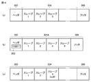
- FIG. 10 is a diagram showing an example of a packet data structure in the PLC system 1 according to the present embodiment.
- FIG. 10A shows an example of a general data structure.
- the packet having the data structure shown in FIG. 10A includes a header 302, a data area group 304, and a footer 306.
- the data area group 304 is divided according to the destination slave device, and stores data to be transmitted.
- Each slave device that has received the packet shown in FIG. 10A knows the data area assigned to the own station in the data area group 304. Extract data.
- FIG. 10B shows a data structure of a packet used in the PLC system 1 according to the present embodiment.
- identification information 303 for specifying a valid slave device as a destination is stored in the header 302 of each packet. Has been.
- Each slave device that has received the packet shown in FIG. 10B refers to the identification information 303 in the header 302 to determine whether or not there is a data area allocated to the own station in the data area group 304. And where the data area is allocated to the own station.
- a flag composed of “0” and “1” is used as the identification information 303, and the slave devices located first and second from the top, that is, slave 1 and slave 2 is stored.
- the third and fourth flags are both set to “0”, data addressed to the third and fourth slave devices, that is, the slaves 3 and 4 are stored. It has been shown. Therefore, even if the slave 3 and the slave 4 receive a packet as shown in FIG. 10B, no data is extracted, and the data is directly transferred to the slave device at the next stage.
- the fifth and sixth slave devices from the head specify that the data addressed to the local station is stored, and extract the data addressed to the local station from the corresponding data area. To do.
- the main processing device 2 stores each data in the packet together with the identification information 303 indicating the remote device 40 (slave device) as the transmission destination.
- Each of the remote devices 40 extracts only the data destined for the own device from the data included in the packet from the main processing device 2 (master device).
- FIG. 10 (c) shows another data structure of a packet used in the PLC system 1 according to the present embodiment.
- the data structure shown in FIG. 10C is similar to the data structure shown in FIG. 10A, but the size of each data area in the data area group 304 can be changed dynamically. That is, data indicating invalidity in a corresponding data area (for example, a null code is input) for a slave device that has no data to be transmitted.
- Each slave device determines that there is no data addressed to itself if a null code is input in the data area assigned to the own station, and without extracting any data, the slave device proceeds to the next slave device. Transfer as it is.
- the data destination may be stored in each data area of the data area group 304 instead of the header 302 of each packet.
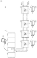
- FIG. 11 is a schematic diagram showing an overall configuration of a PLC system 1A according to a modification of the present embodiment.
- a PLC system 1A includes a main processing device 2 (master device) and one or more remote devices 40 (slave devices), which are connected via a daisy chain type field network. Has been. In the field network, packets are sequentially transferred from the master device to each slave device (down packet), returned at the end, and then sequentially transferred from each slave device to the master device (up packet).
- the CPU unit 10 has a communication processing unit 110A adapted to the daisy chain format. Since other configurations and processes are the same as those described above, detailed description will not be repeated.
- the implementation form of the allocation function of the present embodiment is not limited to the configuration example described above, and various configurations are possible. All of the allocation functions may be implemented in the main processing device 2 (master device) which is a control device, or almost all of the allocation functions may be implemented in the development support device 500. Or the structure which implement
- ⁇ M. Advantage> According to the present embodiment, necessary data can be transmitted from the master device to each of a plurality of slave devices connected to the same network at an update frequency according to the function and processing of each slave device. Therefore, it is possible to effectively use a predetermined network bandwidth. Further, since unnecessary data does not need to be transmitted over the network, the control cycle can be shortened to realize higher speed communication.
Landscapes
- Engineering & Computer Science (AREA)
- Computer Networks & Wireless Communication (AREA)
- Signal Processing (AREA)
- Health & Medical Sciences (AREA)
- Computing Systems (AREA)
- General Health & Medical Sciences (AREA)
- Medical Informatics (AREA)
- Small-Scale Networks (AREA)
- Programmable Controllers (AREA)
Abstract
マスター装置は、スレーブ装置における入出力に関連する処理を含むプログラムを繰り返し実行する実行手段を含む。実行手段がプログラムを実行することで第1のデータおよび第2のデータが算出される。マスター装置は、第1のデータに対する制御周期の整数倍である第1の送信周期の設定と、第2のデータに対する制御周期の整数倍であって第1の送信周期より長い第2の送信周期の設定とに従って、第1の送信周期毎に第1のデータをパケットに割り当てるとともに、第2の送信周期毎に第2のデータをパケットに割り当てる割り当て手段を含む。
Description
本発明は、制御対象を制御するための制御システムおよびそれに向けられる開発支援装置および制御装置、ならびに制御方法に関する。
多くの生産現場で使用される機械や設備は、典型的には、プログラマブルコントローラ(Programmable Logic Controller;以下「PLC」とも称す)などからなる制御システムによって制御される。このような制御システムでは、フィールドの各所にリモート装置を配し、それぞれのリモート装置に対して指令値を与えるとともに、それぞれのリモート装置からフィールド情報を収集する。このような指令値やフィールド情報の伝送は、フィールドネットワークを介して行なわれる。
制御システム内には、互いに異なる機能を提供するリモート装置が存在し、指令値を更新する周期などもそれぞれの機能に適合させることが好ましい。
このようなネットワークを介したデータの受け渡しにおいて、帯域幅に対応して、その優先度に応じてデータの配列などを最適化する技術が開示されている(例えば、特開2012-094944号公報(特許文献1))。
上述の特開2012-094944号公報(特許文献1)に開示される通信帯域制御装置では、通信ドライバとタスクという1対多関係のデータ受け渡しにおいて、送信要求の重要度によるきめ細やかな帯域の指定を実現するものである。これに対して、上述のような制御システムでは、制御周期および帯域が予め定められたネットワークが採用される。そのため、データ毎に帯域を動的に指定するといった先行技術の技術思想を適用することはできない。
本発明は、このような課題を鑑みてなされたものであり、ネットワークを介して接続されたマスター装置および複数のスレーブ装置を含む制御システムにおいて、各スレーブ装置に適した周期でデータを送信することのできる構成を提供することを目的としている。
本発明のある局面に係る制御対象を制御するための制御システムは、マスター装置と、ネットワークを介してマスター装置と接続された複数のスレーブ装置とを含む。マスター装置は、予め定められた制御周期の1または複数毎にネットワーク上にパケットを送出するとともに、複数のスレーブ装置の各々は、マスター装置からのパケットを順次転送するように構成されている。マスター装置は、スレーブ装置における入出力に関連する処理を含むプログラムを繰り返し実行する実行手段を含む。実行手段がプログラムを実行することで第1のデータおよび第2のデータが算出される。マスター装置は、第1のデータに対する制御周期の整数倍である第1の送信周期の設定と、第2のデータに対する制御周期の整数倍であって第1の送信周期より長い第2の送信周期の設定とに従って、第1の送信周期毎に第1のデータをパケットに割り当てるとともに、第2の送信周期毎に第2のデータをパケットに割り当てる割り当て手段を含む。マスター装置は、送信先のスレーブ装置を示す情報とともに、第1のデータおよび第2のデータのそれぞれをパケットに格納し、複数のスレーブ装置の各々は、マスター装置からのパケットに含まれるデータのうち、自装置を宛先とするデータのみを抽出する。
好ましくは、割り当て手段は、各パケットに許容される最大データサイズを超えないように、第1のデータおよび第2のデータのそれぞれをどのパケットに割り当てるかを決定する。
好ましくは、割り当て手段は、送信周期が設定された送信対象の複数のデータのうち、その送信周期が短いデータから順に、パケットへの割り当て方を決定する。
好ましくは、第2のデータは、複数のデータ要素を含む。割り当て手段は、第2のデータに対して同期して送信することが設定されている場合には、第2のデータに含まれる複数のデータ要素が同一のパケットに割り当てられ、第2のデータに対して同期して送信することが設定されていない場合であって、第2のデータに含まれる複数のデータ要素が同一のパケットに割り当てられるように、第2のデータのパケットへの割り当て方を決定する。
さらに好ましくは、割り当て手段は、送信対象の複数のデータのうち、同期して送信することが設定されているデータを他のデータに優先して、パケットへの割り当て方を決定する。
好ましくは、割り当て手段は、各パケットにおける割り当てられたデータの占有状態を通知する手段を含む。
好ましくは、割り当て手段は、第1のデータおよび第2のデータを、制御周期と、第1の送信周期と、第2の送信周期とを含む予め定められた通信パラメータに従う割り当て方の決定ができない場合に、当該通信パラメータの変更を促す通知を行なう手段を含む。
本発明の別の局面によれば、制御対象を制御するための制御システムに向けられた開発支援装置が提供される。制御システムは、マスター装置と、ネットワークを介してマスター装置と接続された複数のスレーブ装置とを含む。マスター装置は、予め定められた制御周期毎にネットワーク上にパケットを送出するとともに、複数のスレーブ装置の各々は、マスター装置からのパケットを順次転送するように構成されている。開発支援装置は、マスター装置がスレーブ装置における入出力に関連する処理を含むプログラムを繰り返し実行することで第1のデータおよび第2のデータを算出するように設定されている場合に、第1のデータに対する制御周期の整数倍である第1の送信周期の設定と、第2のデータに対する制御周期の整数倍であって第1の送信周期より長い第2の送信周期の設定とを含む通信パラメータを受け付ける手段と、第1の送信周期毎に第1のデータがパケットに割り当てられるとともに、第2の送信周期毎に第2のデータがパケットに割り当てられるように割り当て方を決定する割り当て決定手段とを含む。
本発明のさらに別の局面に係るネットワークを介して複数のスレーブ装置と接続される制御装置は、予め定められた制御周期の1または複数毎にネットワーク上にパケットを送出するとともに、複数のスレーブ装置の各々は、制御装置からのパケットを順次転送するように構成されている。制御装置は、スレーブ装置における入出力に関連する処理を含むプログラムを繰り返し実行する実行手段を含む。実行手段がプログラムを実行することで第1のデータおよび第2のデータが算出される。制御装置は、第1のデータに対する制御周期の整数倍である第1の送信周期の設定と、第2のデータに対する制御周期の整数倍であって第1の送信周期より長い第2の送信周期の設定とに従って、第1の送信周期毎に第1のデータをパケットに割り当てるとともに、第2の送信周期毎に第2のデータをパケットに割り当てる割り当て手段とを含む。制御装置は、送信先のスレーブ装置を示す情報とともに、第1のデータおよび第2のデータのそれぞれをパケットに格納し、複数のスレーブ装置の各々は、制御装置からのパケットに含まれるデータのうち、自装置を宛先とするデータのみを抽出する。
本発明のさらに別の局面によれば、制御対象を制御するための制御システムに向けられた開発支援装置が提供される。制御システムは、マスター装置と、ネットワークを介してマスター装置と接続された複数のスレーブ装置とを含む。マスター装置は、予め定められた制御周期の1または複数毎にネットワーク上にパケットを送出するとともに、複数のスレーブ装置の各々は、マスター装置からのパケットを順次転送するように構成されている。マスター装置は、スレーブ装置における入出力に関連する処理を含むプログラムを繰り返し実行する実行手段を備え、実行手段がプログラムを実行することで第1のデータおよび第2のデータが算出される。開発支援装置は、第1のデータに対する制御周期の整数倍である第1の送信周期の設定と、第2のデータに対する制御周期の整数倍であって第1の送信周期より長い第2の送信周期の設定とに従って、第1の送信周期毎に第1のデータがパケットに割り当てられるとともに、第2の送信周期毎に第2のデータがパケットに割り当てられるように割り当て方を決定する。
本発明のさらに別の局面によれば、制御対象を制御するための制御システムにおける制御方法が提供される。制御システムは、マスター装置と、ネットワークを介してマスター装置と接続された複数のスレーブ装置とを含む。制御方法は、マスター装置が予め定められた制御周期の1または複数毎にネットワーク上にパケットを送出するとともに、複数のスレーブ装置の各々がマスター装置からのパケットを順次転送するステップと、マスター装置がスレーブ装置における入出力に関連する処理を含むプログラムを繰り返し実行するステップとを含む。プログラムの実行によって第1のデータおよび第2のデータが算出される。制御方法は、第1のデータに対する制御周期の整数倍である第1の送信周期の設定と、第2のデータに対する制御周期の整数倍であって第1の送信周期より長い第2の送信周期の設定とに従って、第1の送信周期毎に第1のデータをパケットに割り当てるとともに、第2の送信周期毎に第2のデータをパケットに割り当てるステップと、マスター装置が送信先のスレーブ装置を示す情報とともに、第1のデータおよび第2のデータのそれぞれをパケットに格納するステップと、複数のスレーブ装置の各々がマスター装置からのパケットに含まれるデータのうち、自装置を宛先とするデータのみを抽出するステップとを含む。
本発明のある局面に係る制御システムによれば、各スレーブ装置に適した周期でデータを送信することができる。
本発明の実施の形態について、図面を参照しながら詳細に説明する。なお、図中の同一または相当部分については、同一符号を付してその説明は繰り返さない。
本実施の形態では、制御システムの一例として、PLCを中心とするシステムについて例示する。但し、このような制御システムとしては、PLCだけではなく、各種の産業用コンピュータを中心として構成を採用することもできる。さらに、技術の進展によって、新たな処理装置(演算装置)が開発された場合には、そのような新たな処理装置を採用することもできる。
<A.PLCシステムの全体構成>
まず、制御システムの一形態である、本実施の形態に係るPLCシステム1の全体構成について説明する。図1は、本実施の形態に係るPLCシステム1の全体構成を示す模式図である。
まず、制御システムの一形態である、本実施の形態に係るPLCシステム1の全体構成について説明する。図1は、本実施の形態に係るPLCシステム1の全体構成を示す模式図である。
図1を参照して、PLCシステム1は、制御対象を制御するための制御システムであって、メイン処理装置2と、複数のリモート装置40_1,40_2,40_3,…,40_N(以下、「リモート装置40」と総称する場合もある。)とを含む。メイン処理装置2およびリモート装置40は、PLCシステム1の少なくとも一部を構成する制御装置であり、フィールドネットワーク4を介して接続されている。
フィールドネットワーク4を介した通信は、メイン処理装置2によって主体的に制御される。具体的には、メイン処理装置2は、予め定められたタイミングまたは規則に従って、フィールドネットワーク4上を順次伝送されるデータを送信する。以下の説明においては、フィールドネットワーク4上を順次伝送されるデータを「パケット」とも称す。このような意味において、メイン処理装置2を「マスター装置」と称し、リモート装置40_1,40_2,40_3,…,40_Nの各々を「スレーブ装置」とも称す。つまり、制御システムであるPLCシステム1は、メイン処理装置2(マスター装置)と、フィールドネットワーク4を介してメイン処理装置2(マスター装置)と接続された複数のリモート装置40(スレーブ装置)とを含む。
メイン処理装置2は、制御対象を制御するために必要なプログラム(後述するように、ユーザプログラムやシステムプログラムなどを含む)を実行することで、リモート装置40からの入力信号(以下、「フィールド情報」とも称す。)を収集する処理、収集したフィールド情報に基づいて制御演算を行なう処理、制御演算によって算出された指令値をリモート装置40へ出力する処理などを実現する。
メイン処理装置2は、その装置構成として、CPUユニット10と、1つ以上のIOユニット20と、電源ユニット30とを含む。CPUユニット10およびIOユニット20は、図示しない内部バスを介して互いにデータ通信可能に接続されている。電源ユニット30は、CPUユニット10およびIOユニット20へ適切な電圧の電力を供給する。
CPUユニット10は、制御対象を制御するために必要なプログラムを実行する演算部と、フィールドネットワーク4を介したリモート装置40との通信を制御するための通信処理部110とを含む。
CPUユニット10には、各種プログラムのインストール、デバッキング、プログラム実行状態のモニターなどを行なうための開発支援装置500が接続されてもよい。開発支援装置500は、典型的には、汎用コンピュータ上で支援プログラムが実行されることで実現される。支援プログラムには、CPUユニット10をエミュレートして、各種プログラムを模擬的に実行できる機能などが含まれる場合もある。
リモート装置40は、外部のスイッチやセンサからのフィールド情報を受信し、フィールドネットワーク4を介して、その受信したフィールド情報号をメイン処理装置2へ送信する。併せて、リモート装置40は、メイン処理装置2からフィールドネットワーク4を介して受信した指令値を、外部のリレーやアクチュエータへ出力する。あるいは、リモート装置40は、フィールドネットワーク4を介して受信した指令値に従って自身で動作するものであってもよい。例えば、リモート装置40としては、演算機能を持たない単純なIOユニット、演算機能を有するIOユニット、サーボドライバのようなアクチュエータを含む装置、などが想定される。
図1には、リモート装置40がサーボドライバである場合を示し、リモート装置40_1,40_2,40_3,…,40_Nには、それぞれサーボモータ42_1,42_2,42_3,…,42_N(以下、「サーボモータ42」と総称する場合もある。)が接続されており、メイン処理装置2からの指令に応じて、各リモート装置を通じて対応するサーボモータが制御される。
CPUユニット10の通信処理部110は、メイン処理装置2(マスター装置)および複数のリモート装置40(スレーブ装置)が扱うデータを含むデータ列(パケット)のフィールドネットワーク4上での巡回的な伝送を管理するように構成されている。このパケットは、予め定められた制御周期の1または複数毎に送信される。すなわち、メイン処理装置2(マスター装置)は、予め定められた制御周期の1または複数毎にフィールドネットワーク4上にパケットを送信するとともに、複数のリモート装置40(スレーブ装置)の各々は、メイン処理装置2(マスター装置)からのパケットを順次転送するように構成される。
本明細書において、「制御周期」は、ユーザプログラムの処理時間を意味し、予め定められた一定周期の場合もあるし、実行されるユーザプログラムの量などに応じて、動的に変更される場合もある。
図1には、いわゆるリング形式のフィールドネットワークを模式的に示すが、デイジーチェーン接続のフィールドネットワークであってもよい。つまり、本実施の形態に係るフィールドネットワークとしては、データ列(パケット)を予め定められた制御周期の1または複数毎に伝送できる構成であれば、どのような構成を採用してもよい。
<B.CPUユニット10の装置構成>
次に、本実施の形態に係るPLCシステム1に含まれるCPUユニット10の装置構成について説明する。図2は、本実施の形態に係るPLCシステム1に含まれるCPUユニット10の装置構成を示す模式図である。
次に、本実施の形態に係るPLCシステム1に含まれるCPUユニット10の装置構成について説明する。図2は、本実施の形態に係るPLCシステム1に含まれるCPUユニット10の装置構成を示す模式図である。
図2を参照して、CPUユニット10は、通信処理部110に加えて、演算部であるプロセッサ100と、主メモリ102と、不揮発性メモリ104と、内部バスコントローラ108とを含む。これらのコンポーネントは、内部バス109を介して、互いにデータ通信可能に構成される。
プロセッサ100は、制御に係るプログラムを実行する。プロセッサ100は、不揮発性メモリ104などから必要なプログラムを読み出すとともに、主メモリ102に展開して実行する。不揮発性メモリ104は、制御に係るプログラムとして、ユーザプログラム105およびシステムプログラム106を格納している。プロセッサ100のプログラムの実行に係るデータは、主メモリ102内のワークエリア103に格納される。
内部バスコントローラ108は、図示しない内部バスを介してIOユニット20と接続され、プロセッサ100とIOユニット20との間のデータ(フィールド情報および指令値)の遣り取りを仲介する。
通信処理部110は、フィールドネットワーク4を介してリモート装置40と接続され、CPUユニット10とリモート装置40との間のデータ(フィールド情報および指令値)の遣り取りを仲介する。より具体的には、通信処理部110は、通信コントローラ112と、共有メモリ114と、送信バッファ120と、送信回路122と、受信バッファ130と、受信回路132とを含む。
送信バッファ120および送信回路122は、通信処理部110から外部装置へのフレーム送信に係る処理を実現し、受信バッファ130および受信回路132は、外部装置から通信処理部110へのフレーム送信に係る処理を実現する。通信処理部110は、共有メモリ114を有しており、プロセッサ100は、算出した指定値を共有メモリ114に書き込むとともに、共有メモリ114からフィールド情報を読み出す。つまり、共有メモリ114に書き込まれた指令値は、送信バッファ120へ転送され、送信バッファ120からリモート装置40へ送信される。また、リモート装置40から取得されたフィールド情報は、受信バッファ130で受信された後、共有メモリ114へ転送される。
通信処理部110における一連の処理は、通信コントローラ112によって実行される。より具体的には、通信コントローラ112は、プロセッサ100などからの指令に従って、パケットを生成し送信されるとともに、受信されたパケットから必要な情報を抽出したりする。
通信処理部110は、ソフトウェアを用いて、その一部または全部を実現してもよい。あるいは、ASIC(Application Specific Integrated Circuit:特定用途向集積回路)やFPGA(Field-Programmable Gate Array)などのハード回路を用いて、その一部または全部を実現してもよい。
<C.リモート装置40の装置構成>
次に、本実施の形態に係るPLCシステム1に含まれるリモート装置40の装置構成について説明する。図3は、本実施の形態に係るPLCシステム1に含まれるリモート装置40の装置構成の一例を示す模式図である。
次に、本実施の形態に係るPLCシステム1に含まれるリモート装置40の装置構成について説明する。図3は、本実施の形態に係るPLCシステム1に含まれるリモート装置40の装置構成の一例を示す模式図である。
本実施の形態に係るリモート装置40としては、各種の構成を採用することができるが、図3には、演算機能およびIO機能を有する構成例を示す。図3を参照して、リモート装置40は、演算処理部400と、入力回路402と、出力回路404と、通信処理部410とを含む。
演算処理部400は、フィールドネットワーク4を介して送信されたパケットに基づいて、予め定められた処理を実行するとともに、処理の結果得られるパケットを、フィールドネットワーク4を介して送信させる。
入力回路402は、フィールド側から入力された信号(フィールド情報)を演算処理部400へ出力する。出力回路は、演算処理部400から与えられた指令値に応じた信号をフィールド側へ出力する。
通信処理部410は、フィールドネットワーク4を介してCPUユニット10と接続され、リモート装置40とCPUユニット10との間のデータ(フィールド情報および指令値)の遣り取りを仲介する。より具体的には、通信処理部410は、通信コントローラ412と、共有メモリ414と、送信バッファ420と、送信回路422と、受信バッファ430と、受信回路432とを含む。これらのコンポーネントは、上述の通信コントローラ112、共有メモリ114、送信バッファ120、送信回路122、受信バッファ130、および、受信回路132(いずれも図2)と同様の機能を有しているので、詳細な説明は繰り返さない。但し、スレーブ装置の一部である通信処理部410でのパケットを受信した際の処理、および、パケットを送信する際の処理については、マスター装置の一部であるCPUユニット10の通信処理部110での処理とは異なっている。
リモート装置40(演算処理部400、入力回路402、出力回路404、および通信処理部410)については、ソフトウェアを用いてその機能の全部または一部を実現してもよいが、ASICやFPGAなどのハード回路を用いて、その一部または全部を実現するのが好ましい。
<D.フィールドネットワーク4>
次に、フィールドネットワーク4における通信処理について説明する。
次に、フィールドネットワーク4における通信処理について説明する。
フィールドネットワーク4での通信方式としては、予め定められた制御周期の1または複数毎にパケット伝送が可能な(つまり、リアルタイム通信可能な)方式が好ましい。一例として、フィールドネットワーク4としては、各種の産業用イーサネット(登録商標)を用いることができる。産業用イーサネット(登録商標)の具体例としては、例えば、EtherCAT(登録商標)、PROFINET IRT、MECHATROLINK(登録商標)-III、Powerlink、SERCOS(登録商標)-III、CIP Motionなどがある。さらに、産業用イーサネット(登録商標)以外のフィールドネットワークを用いてもよい。例えば、DeviceNet、CompoNet(登録商標)などを用いてもよい。
<E.概要>
次に、本実施の形態に係るPLCシステム1における処理の概要について説明する。図4は、本実施の形態に係るPLCシステム1における処理の概要を説明するための図である。図4(a)は、関連技術に係るパケットのデータ構造を示す図であり、図4(b)は、本実施の形態に係るパケットのデータ構造を示す図である。
次に、本実施の形態に係るPLCシステム1における処理の概要について説明する。図4は、本実施の形態に係るPLCシステム1における処理の概要を説明するための図である。図4(a)は、関連技術に係るパケットのデータ構造を示す図であり、図4(b)は、本実施の形態に係るパケットのデータ構造を示す図である。
一般的なフィールドネットワークでは、図4(a)に示すように、各パケットに格納されるデータ種類は一律になっている。つまり、各パケットは、同一のデータ構造を有しており、同一種類のデータセットが予め定められた制御周期の1または複数毎に送信されることになる。図4(a)に示す例では、各パケットは、いずれもスレーブ1~スレーブ6のそれぞれに向けられるデータを含むことになる。
例えば、図1に示すような複数のサーボモータ42を用いて、多軸制御を行なおうとすれば、各軸についての指令値を各パケットに格納する必要があり、そのデータ長が長くなる。すなわち、制御対象の軸数が多くなるほど、制御周期T1(つまり、リモート装置40における制御周期)はその軸数に比例して長くなる。
しかしながら、現実的には、高速な応答が必要な軸とそうではない軸とが混在することも多い。このような軸数の多いシステムでは、高速な応答ではない軸に対しても、より高速な応答が必要な軸と同程度の制御周期で指令値が送信されるため、かえって高速な応答が必要な軸に対して制約が生じ得る。
図4(a)に示すような比較的軸数が多い構成では、すべての軸に対する指令値のセットで1パケットを構成して転送されるため、軸数に比例して制御周期はT1になっている。言い換えれば、各サーボモータ42では、制御周期T1より高速な応答を実現できないことになる。
これに対して、本実施の形態においては、各リモート装置40における速度要求に応じて、制御周期を実質的に可変にする。すなわち、複数のサーボモータ42を制御する構成においては、要求される応答時間に応じた制御周期を軸毎に設定し、その設定された制御周期に応じたパケットを生成する。これにより、設定されたそれぞれの制御周期を実現する。
例えば、図4(b)の例では、各パケットの制御周期をT2とした場合において、スレーブ1およびスレーブ2に対する制御周期はT2に設定され、スレーブ3~スレーブ6に対する制御周期はT2×2に設定されるとする。各パケットは、スレーブ1およびスレーブ2に対する指令値をいずれも含むが、スレーブ3~スレーブ6に対する指令値は、2回のうち一方のパケットにのみ含まれることになる。つまり、スレーブ3およびスレーブ4に対する指令値は奇数番目のパケットにのみ含まれ、スレーブ5およびスレーブ6に対する指令値は偶数番目のパケットにのみ含まれる、といった具合である。
このようなパケットを生成することで、スレーブ1およびスレーブ2では、制御周期T2と同じ制御周期を実現でき、スレーブ3~スレーブ6では、制御周期T2の2倍の制御周期を実現できる。つまり、図4(b)に示す例では、高速な応答が必要な軸は制御周期T毎に通信し、そうではない軸は複数回に一回通信することで、一回あたりのパケットのデータサイズを低減でき、それによって制御周期をより短くすることができるので、高速な応答を実現できる。
以下に説明するように、本実施の形態においては、制御システム内のスレーブ装置の数および各スレーブ装置における制御周期の要求に応じて、各パケットに格納されるデータ構造を周期毎に動的に変化させることで、要求を満たす制御を実現する。
<F.パケット生成処理>
次に、本実施の形態に係るPLCシステム1におけるパケット生成の処理について説明する。図5は、本実施の形態に係るPLCシステム1に含まれるパケット生成の処理について説明するための図である。
次に、本実施の形態に係るPLCシステム1におけるパケット生成の処理について説明する。図5は、本実施の形態に係るPLCシステム1に含まれるパケット生成の処理について説明するための図である。
図5を参照して、ユーザプログラム105は、複数の処理A,B,C,Dを含み、各処理が互いに独立して予め定められた制御周期で繰り返し実行されるとする。ここでは、複数の処理A,B,C,Dの送信周期は、それぞれAs,Bs,Cs,Dsであるとする。処理A,B,C,Dの各々は、リモート装置40などから収集したフィールド情報を入力として用いるとともに、その実行によって、出力情報A(n),B(n),C(n),D(n)(但し、nは1以上の整数)を算出する。なお、説明の便宜上、配列形式で出力情報を定義するが、必ずしも配列形式で格納される必要はなく、任意の配置および形式で格納されてもよい。出力情報A(n),B(n),C(n),D(n)は、主メモリ102内のワークエリア103に格納され、対応する処理の制御周期で逐次更新される。つまり、メイン処理装置2(マスター装置)は、リモート装置40(スレーブ装置)における入出力に関連する処理を含むユーザプログラム105を繰り返し実行するプロセッサ100(実行手段)を含む。プロセッサ100(実行手段)は、ユーザプログラム105を実行することで複数種類のデータを算出する。
ワークエリア103に格納される出力情報は、予め定められた割り当て設定150に従って選択され、パケットNt1,Nt2,Nt3,Nt4,…が順次生成される。図5に示す例では、処理Aによって算出される出力情報A(n)は、生成される各パケットに割り当てられる。つまり、出力情報A(n)は、パケットの制御周期毎に送信される。これに対して、出力情報B(n),C(n),D(n)の通信頻度(制御周期/送信周期)は、出力情報A(n)の1/3に設定されている。つまり、出力情報B(n),C(n),D(n)は、3回のうち1回の割合で送信されることになる。言い換えれば、出力情報B(n),C(n),D(n)は、パケットの制御周期の3倍に相当する周期で更新されることになる。
このように、処理の種別および/または出力情報の内容に応じて、リモート装置40に対して与えるデータの通信頻度(周期)を最適化することで、各パケットのデータサイズが過度に大きくなり、制御周期を短くできないという事態を回避することができる。つまり、フィールドネットワーク4が予め用意している通信帯域を有効に利用して、リモート装置40の数が多い場合であっても、高速な応答が必要なリモート装置40に対しては、より短い制御周期で指令値を与えることができる。
上述の説明では、ユーザプログラム105に含まれる処理によって算出される出力情報A(n),B(n),C(n),D(n)をメイン処理装置2から複数のリモート装置40へ送信する処理例について説明したが、メイン処理装置2がそれぞれのリモート装置40からフィールド情報を収集する処理にも同様に適用できる。リモート装置40からフィールド情報を収集する場合には、対象のリモート装置40に対して、フィールド情報を取得するためのコマンド(以下、「データリフレッシュ命令」とも称す。)を送信することになる。そのため、このデータリフレッシュ命令を、上述のように、処理の種別および/または必要なフィールド情報などに応じて、適切な制御周期で送信することで、フィールドネットワーク4が予め用意している通信帯域を有効に利用して、高速な応答にも対応するデータ通信を実現できる。
<G.パケットへの割り当て処理の具体例>
次に、具体例を用いて、パケットへの割り当て処理の一例について説明する。送信対象の出力情報のパケットへの割り当て処理、つまり割り当て設定150を決定する処理は、典型的には、CPUユニット10のプロセッサ100が実行する。但し、CPUユニット10に接続される開発支援装置500などのオフライン環境で実行してもよい。
次に、具体例を用いて、パケットへの割り当て処理の一例について説明する。送信対象の出力情報のパケットへの割り当て処理、つまり割り当て設定150を決定する処理は、典型的には、CPUユニット10のプロセッサ100が実行する。但し、CPUユニット10に接続される開発支援装置500などのオフライン環境で実行してもよい。
(g1:通信パラメータ)
図6は、本実施の形態に係るPLCシステム1で用いられる通信パラメータの一例を示す図である。図6を参照して、例えば、複数の処理A,B,C,Dが繰り返し実行されるとし、各処理の実行周期である送信周期As,Bs,Cs,Dsは、それぞれ250μsec,500μsec,1000μsec,1000μsecであるとする。
図6は、本実施の形態に係るPLCシステム1で用いられる通信パラメータの一例を示す図である。図6を参照して、例えば、複数の処理A,B,C,Dが繰り返し実行されるとし、各処理の実行周期である送信周期As,Bs,Cs,Dsは、それぞれ250μsec,500μsec,1000μsec,1000μsecであるとする。
処理A,B,C,Dは、それぞれ出力情報A(n),B(n),C(n),D(n)を出力するとする。各出力情報に含まれるデータ数Ac,Bc,Cc,Dcは、それぞれ3,4,4,1であるとする。つまり、出力情報A(n)は、3つのデータ要素A(1),A(2),A(3)を含んでおり、出力情報B(n)およびC(n)は、いずれも4つのデータ要素B(1),B(2),B(3),B(4)およびデータ要素C(1),C(2),C(3),C(4)をそれぞれ含んでおり、出力情報D(n)は、1つのデータ要素D(1)からなる。
出力情報A(n),B(n),C(n),D(n)にそれぞれ対応するパケット占有時間Ap,Bp,Cp,Dpは、対応するデータ要素をパケットに割り当てた際に必要となる占有時間を示し、各データ要素の長さや型に応じて変化し得る。つまり、パケット占有時間は、対応するデータ要素のデータサイズを意味し、制御周期Tcは、1パケットあたり送信できる最大データサイズを意味する。
但し、パケット占有時間に代えて、データ要素のデータサイズをそのまま用いて評価してもよい。つまり、制御周期Tcを用いて、各パケットに割り当て可能なデータサイズ(最大データサイズ)を先に決定するとともに、割り当て対象の各データ要素のデータサイズを用いて、割り当て方法を決定してもよい。
図6に示す例では、出力情報A(n)およびD(n)についてのパケット占有時間ApおよびDpは、いずれも30μsecであり、出力情報B(n)およびC(n)についてのパケット占有時間BpおよびCpは、いずれも35μsecである。
制御周期Tcは、パケットの生成周期を示す。処理A,B,C,Dのそれぞれについての通信頻度Af,Bf,Cf,Dfは、制御周期Tcを基準として、パケットにどの程度対応する出力情報を割り当てるかを示す値である。例えば、処理Aについての通信頻度Afは、0.5であり、2回のパケットが送信される毎にいずれかのパケットに対応する出力情報A(n)をコピーすることを意味する。また、処理Bについての通信頻度Bfは、0.25であり、4回のパケットが送信される毎にいずれかのパケットに対応する出力情報B(n)をコピーすることを意味する。また、処理CおよびDについての通信頻度CfおよびDfは、いずれも0.125であり、8回のパケットが送信される毎にいずれかのパケットに対応する出力情報C(n)およびD(n)をそれぞれコピーすることを意味する。したがって、出力情報A(n)の送信周期は制御周期Tc×2であり、出力情報B(n)の送信周期は制御周期Tc×4であり、出力情報C(n)およびD(n)の送信周期は制御周期Tc×8であるように、データ要素のパケットへの割り当てを行なう必要がある。
図6に示す通信パラメータのうち、「同期」の欄は、対応する出力情報内のデータセットを同一のパケットで送信する必要があるか否かを示す。例えば、出力情報A(n)およびD(n)については、「同期」が「必要」であると指定されており、これらの出力情報内のデータセットは、同一のパケットに割り当てられる。つまり、これらの出力情報内のデータセットを同期して送信することが設定されている。これに対して、出力情報B(n)およびC(n)については、「同期」が「必要ではない」であると指定されており、これらの出力情報内のデータセットについては、一部のデータと残りのデータとが異なるパケットに割り当てられることが許容される。例えば、3軸のモーション制御などでは、各軸に対する指令を同時に更新する必要があり、このようなアプリケーションに用いられる出力情報については、同期が必要であると設定される。これに対して、それぞれ独立した制御に用いられる出力情報であれば、同一のタイミングで更新される必要はなく、このような場合には、同期は必要ではないと設定される。
(g2:パケットの生成処理)
図7は、図6に示す通信パラメータに従うパケットの生成処理の一例を説明するための図である。図7(a)~(c)を参照して、図6に示す通信パラメータに従って、どのように割り当て設定が決定されるのかを説明する。
図7は、図6に示す通信パラメータに従うパケットの生成処理の一例を説明するための図である。図7(a)~(c)を参照して、図6に示す通信パラメータに従って、どのように割り当て設定が決定されるのかを説明する。
なお、最も高い通信頻度(制御周期/最も短い送信周期)>1である場合には、現状の制御周期では、要求を満足できないので、送信周期、パケット占有時間、制御周期などを見直す必要がある。
まず、図6に示す通信パラメータに基づいて、要求される通信頻度が高い(つまり、要求される送信周期が短い)出力情報について優先的に割り当て方が決定される。但し、同期が必要である出力情報が含まれる場合には、それらの出力情報が優先される。
図6に示す通信パラメータでは、出力情報A(n)およびD(n)に対して同期が必要であると設定されており、これらの同期が必要な出力情報のうち、出力情報A(n)には、より高い通信頻度が設定されている。そのため、第1番目に、同期が必要であって、通信頻度が最も高い出力情報A(n)のデータセット全体を、通信頻度Af(=制御周期Tc/送信周期)の逆数に1回の頻度で割り当てるように割り当て方を決定する。図6に示す例では、出力情報A(n)の通信頻度は0.5であるので、出力情報A(n)は制御周期Tcの2回に1回の頻度でパケットに割り当てられる。つまり、出力情報A(n)に含まれる3つのデータ要素A(1),A(2),A(3)が単一のデータパケットに割り当てられる。
併せて、各パケットにデータ要素が割り当てられた際に、当該パケットにおけるパケット占有時間の合計が制御周期Tcを超えないように最適化される。
図7(a)には、奇数番目のパケット、つまりパケットNt1,Nt3,Nt5,Nt7,Nt9,Nt11,Nt13,…の各々に、出力情報A(n)に含まれる3つのデータ要素A(1),A(2),A(3)が割り当てられる例を示す。
図7(a)に示す状態において、奇数番目の各パケットにおける出力情報A(n)についてのパケット占有時間の合計は、パケット占有時間Ap×データ数Ac=90μsecとなり、パケット占有時間Ap×データ数Ac<制御周期Tc(125μsec)の条件を満たすことになる。
2番目に、もう一つの同期が必要な出力情報D(n)のデータセット全体を、通信頻度Dfの逆数に1回の頻度で割り当てるように割り当て方を決定する。出力情報D(n)の通信頻度は0.125であるので、出力情報D(n)は制御周期Tcの8回に1回の頻度でパケットに割り当てられる。図7(a)に示す状態において、奇数番目のパケットにはまだ余裕があるので、パケットNt1,Nt9,…の各々に、出力情報D(n)に含まれる1つのデータ要素D(1)が割り当てられる例を示す。
この状態において、1,9,17,…番目の各パケットにおけるパケット占有時間の合計は、パケット占有時間Ap×データ数Ac+パケット占有時間Dp×データ数Dc=120μsecとなり、制御周期Tc(125μsec)の条件を満たすことになる。
上述のような、同期が必要である出力情報を割り当てた時点で、パケット占有時間の合計に関する条件が成立しない場合には、送信周期、パケット占有時間、制御周期などを見直す必要がある。
このように、メイン処理装置2(マスター装置)は、出力情報A(n)(第1のデータ)に対する制御周期Tcの整数倍(×2)である第1の送信周期の設定と、出力情報D(n)(第2のデータ)に対する制御周期Tcの整数倍(×8)であって第1の送信周期より長い第2の送信周期の設定とに従って、各パケットに許容される最大データサイズ(制御周期Tc)を超えないように、制御周期毎に送出されるパケットのいずれかに出力情報D(n)(第1のデータ)を第1の送信周期毎に割り当てるとともに、制御周期Tc1毎に送出されるパケットのいずれかに出力情報D(n)(第2のデータ)を第2の送信周期毎に割り当てるように割り当て方を決定する機能を含む。このとき、割り当て機能は、送信周期が設定された送信対象の複数のデータのうち、その送信周期が短いデータから順に、パケットへの割り当てを行なう。
次に、同期が必要ではない出力情報のうち、通信頻度が高いものから順次、パケットに割り当てられる。図6に示す通信パラメータでは、3番目に、同期が必要ではなく、通信頻度が最も高い出力情報B(n)に含まれるデータ要素B(1),B(2),B(3),B(4)を割り当てるように割り当て方を決定する。ここで、データ要素B(1),B(2),B(3),B(4)の各々を、通信頻度Bf(=制御周期Tc/送信周期)の逆数に1回の頻度で割り当てるように割り当て方を決定する。但し、各データ要素が異なるパケットに割り当てられてもよい。このとき、割り当てられる頻度が指定された値になること、および、各パケットにおけるパケット占有時間の合計が制御周期を超えないこと、の2つの条件を満足するように、割り当てが行なわれる。すなわち、各パケットにおける占有率(パケット占有時間の合計/制御周期Tc)が、1を超えないように、出力情報Bが順次割り当てられる。なお、出力情報Bは同期が必要ではないので、要求された通信頻度を確保できれば、同の一パケットにすべてのデータ要素を配置する必要はない。
例えば、図7(a)に示す状態において、データ要素B(1)をパケットNt1に割り当てると、パケット占有時間の合計は、パケット占有時間Ap×データ数Ac+パケット占有時間Dp×データ数Dc+パケット占有時間Bp×(データ数Bc-3)=155μsec>制御周期Tcとなり、条件を満足しない。そのため、データ要素B(1)は、次のパケットNt2に割り当てられる。
図7(b)には、出力情報B(n)に含まれるデータ要素B(1),B(2),B(3),B(4)のすべてが割り当てられた状態を示す。この状態において、データ要素B(1),B(2),B(3)は、パケットNt2,Nt6,Nt10,…の各々に割り当てられる。
図7(b)に示す状態において、2,6,10,…番目の各パケットにおけるパケット占有時間の合計は、パケット占有時間Bp×(データ数Bc-1)=105μsecとなり、パケット占有時間Bp×(データ数Bc-1)<制御周期Tc(125μsec)の条件を満たすことになる。
ここで、パケット占有時間Bp×データ数Bc=140>制御周期Tc(125μsec)となるので、データ要素B(4)をデータ要素B(1),B(2),B(3)と同じパケットNt2に割り当てることはできない。さらに、奇数番目であるパケットNt3については、そのパケット占有時間の合計が制限値に近いので、データ要素B(4)は、必然的にパケットNt4へ割り当てられる。以下同様にして、データ要素B(4)は、パケットNt4,Nt8,Nt12,…の各々に割り当てられる。
次に、出力情報C(n)に含まれるデータ要素C(1),C(2),C(3),C(4)の割り当て方を決定する。ここで、データ要素C(1),C(2),C(3),C(4)の各々を、通信頻度Cf(=制御周期Tc/送信周期)の逆数に1回の頻度で割り当てるように決定する。但し、各データ要素が異なるパケットに割り当てられてもよい。このとき、割り当てられる頻度が指定された値になること、および、各パケットにおけるパケット占有時間の合計が制御周期を超えないこと、の2つの条件を満足するように、割り当てが行なわれる。すなわち、各パケットにおける占有率(パケット占有時間の合計/制御周期Tc)が、1を超えないように、出力情報Cが順次割り当てられる。なお、出力情報Cは同期が必要ではないので、要求された通信頻度を確保できれば、同の一パケットにすべてのデータ要素を配置する必要はない。
図7(b)に示す状態において、パケットNt1,Nt2,Nt3については、そのパケット占有時間の合計が制限値に近いので、出力情報C(n)は、必然的にパケットNt4へ割り当てられる。このとき、出力情報C(n)の割り当てられるデータ要素が2つであれば、パケット占有時間Bp×(データ数Bc-3)+パケット占有時間Cp×(データ数Cc-2)=105<制御周期Tcが成立するが、出力情報C(n)の割り当てられるデータ要素が3つになると、パケット占有時間Bp×データ数Bc+パケット占有時間Cp×(データ数Cc-1)=140>制御周期Tcとなるので、データ要素は2つしか割り当てることができない。
パケットNt5,Nt6,Nt7については、そのパケット占有時間の合計が制限値に近いので、出力情報C(n)の残りのデータ要素は、パケットNt8へ割り当てられる。パケットNt8において、パケット占有時間Bp×(データ数Bc-3)+パケット占有時間Cp×(データ数Cc-2)=105<制御周期Tcが成立する。
図7(c)には、出力情報A(n),出力情報B(n),出力情報C(n),出力情報D(n)に含まれるデータ要素のすべてが割り当てられた状態を示す。割り当て設定150(図5)は、この割り当て状態を定義する。
なお、上述のような、同期が必要ではないいずれかの出力情報を割り当てた時点で、パケット占有時間の合計に関する条件が成立しない場合には、送信周期、パケット占有時間、制御周期などを見直す必要がある。
図8は、図7(c)に示す出力情報がパケットに割り当てられた状態におけるパケット占有時間の合計および占有率を示す図である。図8に示すように、いずれのパケットにおいても、パケット占有時間の合計は、合計が制御周期Tc(125μsec)を超えておらず、その結果、占有率はいずれも1未満であることが判る。
上述したように、アプリケーションによっては、出力情報に含まれる複数のデータ要素に対して、同期が必要であるか否かを設定できることが好ましい。つまり、出力情報が複数のデータ要素を含む場合には、割り当て機能は、当該出力情報に対して同期して送信することが設定されている場合には、当該出力情報に含まれる複数のデータ要素を同一のパケット(すなわち、単一のパケットまたは共通のパケット)に割り当てるように割り当て方を決定する。一方、割り当て機能は、出力情報に対して同期して送信することが設定されていない場合であって、当該出力情報に含まれる複数のデータ要素を同一のパケットに割り当てることができないときには、複数のデータ要素を複数のパケットに亘って割り当てるように割り当て方を決定する。ここで、割り当て機能は、送信対象の複数の出力情報のうち、同期して送信することが設定されている出力情報を他のデータに優先して、パケットへの割り当てを行なう。
以上のような手順によって、各出力情報が指定された通信頻度で送信されるとともに、パケット占有時間の合計などの条件が満足されるように、各出力情報が適宜割り当てられる。
<H.処理手順>
以下、本実施の形態に係るPLCシステム1における処理手順について説明する。図9は、本実施の形態に係るPLCシステム1における処理手順を示すフローチャートである。なお、図9には、上述したようなデータ送信に関連する処理のみを例示的に示す。図9に示す各ステップは、典型的には、メイン処理装置2のCPUユニット10のプロセッサ100によって実行される。但し、開発支援装置500において、オフラインで仮想的に以下の各ステップを実行することもできる。つまり、開発支援装置500は、メイン処理装置2のCPUユニット10と実質的に同等の機能を有している。
以下、本実施の形態に係るPLCシステム1における処理手順について説明する。図9は、本実施の形態に係るPLCシステム1における処理手順を示すフローチャートである。なお、図9には、上述したようなデータ送信に関連する処理のみを例示的に示す。図9に示す各ステップは、典型的には、メイン処理装置2のCPUユニット10のプロセッサ100によって実行される。但し、開発支援装置500において、オフラインで仮想的に以下の各ステップを実行することもできる。つまり、開発支援装置500は、メイン処理装置2のCPUユニット10と実質的に同等の機能を有している。
まず、プロセッサ100は、ユーザプログラム105および各種設定を受け付けて、不揮発性メモリ104に格納する(ステップS2)。続いて、プロセッサ100は、ユーザプログラム105に含まれる各処理によって算出される出力情報を指定された通信頻度で送信するための割り当て処理(以下に説明するステップS10~S34)を実行する。
より具体的には、プロセッサ100は、ユーザなどから指定された通信パラメータ(図6など参照)を読み出して送信対象の出力情報を特定する(ステップS10)。続いて、プロセッサ100は、読み出した通信パラメータを参照して、送信対象の出力情報のうち、同期が必要であると設定されている出力情報が存在するか否かを判断する(ステップS12)。同期が必要であると設定されている出力情報が存在する場合(ステップS12においてYESの場合)には、プロセッサ100は、同期が必要であると設定されている出力情報のうち、最も通信頻度が高い出力情報を選択する(ステップS14)。そして、プロセッサ100は、割り当てられる頻度が指定された通信頻度と一致すること、および、各パケットにおけるパケット占有時間の合計が制御周期を超えないこと、の2つの条件を満足するように、選択された出力情報のいずれかのパケットへの割り当てを試みる(ステップS16)。プロセッサ100は、選択された出力情報のすべてのパケットへの割り当てが成功したか否かを判断する(ステップS18)。
選択された出力情報のすべてをパケットへ割り当てることができなかった場合(ステップS18においてNOの場合)には、指定された通信パラメータを実現できない旨、および、送信周期、パケット占有時間、制御周期などの見直しが必要である旨をユーザへ通知する(ステップS32)。そして、処理は終了する。
これに対して、選択された出力情報のすべてのパケットへの割り当てが成功した場合(ステップS18においてYESの場合)には、プロセッサ100は、同期が必要であると設定されている出力情報のうち、パケットへの割り当てが完了していないものがあるか否かを判断する(ステップS20)。同期が必要であると設定されている出力情報のうち、パケットへの割り当てが完了していないものがある場合(ステップS20においてYESの場合)には、パケットへの割り当てが完了していない出力情報のうち、最も通信頻度が高い出力情報を選択する(ステップS22)。そして、プロセッサ100は、ステップS16以下の処理を繰り返す。
これに対して、同期が必要であると設定されている出力情報のすべてについて、パケットへの割り当てが完了している場合(ステップS20においてNOの場合)、または、同期が必要であると設定されている出力情報が存在しない場合(ステップS12においてNOの場合)には、プロセッサ100は、パケットへの割り当てが完了していない出力情報が存在するか否かを判断する(ステップS24)。
パケットへの割り当てが完了していない出力情報が存在する場合(ステップS24においてYESの場合)には、プロセッサ100は、パケットへの割り当てが完了していない出力情報のうち、最も通信頻度が高い出力情報を選択する(ステップS26)。そして、プロセッサ100は、割り当てられる頻度が指定された通信頻度と一致すること、および、各パケットにおけるパケット占有時間の合計が制御周期を超えないこと、の2つの条件を満足するように、選択された出力情報のいずれかのパケットへの割り当てを試みる(ステップS28)。プロセッサ100は、選択された出力情報のすべてのパケットへの割り当てが成功したか否かを判断する(ステップS30)。
選択された出力情報のすべてのパケットへの割り当てが成功しなかった場合(ステップS30においてNOの場合)には、処理はステップS32へ進む。
これに対して、選択された出力情報のすべてをパケットへ割り当てることができなかった場合(ステップS30においてYESの場合)には、プロセッサ100は、ステップS24以下の処理を繰り返す。
最終的に、出力情報のすべてについて、パケットへの割り当てが完了している場合(ステップS24においてNOの場合)には、プロセッサ100は、割り当て完了の状態を示す割り当て設定150を生成し、格納する(ステップS34)。
その後、何らかの明示的または暗示的な指示に応答して、プロセッサ100は、制御対象を制御するために必要なプログラム(ユーザプログラム105およびシステムプログラム106を含む)の実行を開始する(ステップS40)。そして、プロセッサ100は、プログラムの実行により算出された情報を、ステップS34において格納した割り当て設定150に従って割り当て方を決定することで、パケットを制御周期毎に生成する(ステップS42)。以下、ステップS40およびS42の処理が繰り返される。
<I.ユーザ支援機能>
上述した、パケットへの割り当て処理では、基本的には、設定された通信パラメータに従って、それぞれの出力情報を自動的に各パケットに割り当てる処理について説明した。これに加えて、割り当て後の結果に対して、さらなる最適化を支援する機能について説明する。具体的には、予め設定された通信パラメータでは設定できないような場合に、どのように修正すればよいかをガイドするような機能ついて説明する。また、予め設定された通信パラメータに対して、さらに制御周期を短縮できるか否かをユーザへ通知するような機能について説明する。これらの機能を実装することは、ユーザ支援やユーザビリティの観点から好ましい。
上述した、パケットへの割り当て処理では、基本的には、設定された通信パラメータに従って、それぞれの出力情報を自動的に各パケットに割り当てる処理について説明した。これに加えて、割り当て後の結果に対して、さらなる最適化を支援する機能について説明する。具体的には、予め設定された通信パラメータでは設定できないような場合に、どのように修正すればよいかをガイドするような機能ついて説明する。また、予め設定された通信パラメータに対して、さらに制御周期を短縮できるか否かをユーザへ通知するような機能について説明する。これらの機能を実装することは、ユーザ支援やユーザビリティの観点から好ましい。
例えば、一旦割り当てられた結果について、図8に示すような、各パケットにおけるパケット占有時間の合計を算出する。図8に示すような各パケットにおけるパケット占有時間の合計を任意の形式(リスト形式やグラフ表示)でユーザへ提示するようにしてもよい。つまり、本実施の形態に係る割り当て処理は、各パケットにおける割り当てられたデータの占有状態(例えば、占有率や占有時間)を通知する処理を含む。
出力情報を同期させてパケットへの割り当て方を決定する場合、いずれかのパケットにおいて、そのパケット占有時間の合計が制御周期を超えると、エラーとして判断される。つまり、本実施の形態に係る割り当て処理は、割り当て対象のデータ要素を、制御周期や送信周期を含む予め定められた通信パラメータに従って割り当てができない場合に、当該通信パラメータの変更を促す通知を行なう処理を含む。
このような場合には、以下のような手法によって、エラーが生じないように調整が行なわれてもよい。
(1)各パケットにおけるパケット占有時間の合計に適合するように、制御周期を長くする。この場合には、ユーザに対して、制御周期をどの程度まで長くすればエラーが解消するのかといったメッセージを通知してもよい。つまり、算出された各パケットにおけるパケット占有時間の合計の最大値を提示して、制御周期をその最大値より長くなるようにガイドする。あるいは、制御周期を自動的に長くするようにしてもよい。
(2)制御周期に適合するように、各パケットにおけるパケット占有時間の合計を短くする。この場合には、各パケットに割り当てる出力情報を減らし、パケット占有時間の合計を短縮することになる。あるいは、同期の対象になっている出力情報の設定を変更するという対処が可能である)。
また、フィールドネットワーク4を効率的に利用することを考えると、図8に示す、出力情報がパケットに割り当てられた状態におけるパケット占有時間の合計および占有率を示す結果を参照しつつ、以下のようなアプローチをとることができる。
・同期が必要であると設定されている出力情報が割り当てられている奇数番目のパケットNt1,Nt3,Nt5,Nt7…のパケット占有率のうち最も高い値を1に近づけることができる。
・各出力情報のパケット占有時間を延ばすことや、制御周期を短くすることができる。
・パケット占有率が1に近づくまで、出力情報(例えば、出力情報E)を追加することができる。
・パケット占有率が1に近づくまで、出力情報(例えば、出力情報E)を追加することができる。
・パケット占有率が1に近づくまで、パケット占有時間を長くして送信する情報量を増加させることができる。
<J.スレーブ装置におけるデータ受信処理>
上述したように、本実施の形態に係るPLCシステム1では、制御周期毎に送出されるパケットに格納されるデータの構造は画一的なものではなく、動的に変化する。そのため、各パケットに含まれる各データの宛先も画一的なものではない。そのため、このように、その格納されるデータが時間的に変化するパケットを受信する各スレーブ装置におけるデータ受信処理について説明する。
上述したように、本実施の形態に係るPLCシステム1では、制御周期毎に送出されるパケットに格納されるデータの構造は画一的なものではなく、動的に変化する。そのため、各パケットに含まれる各データの宛先も画一的なものではない。そのため、このように、その格納されるデータが時間的に変化するパケットを受信する各スレーブ装置におけるデータ受信処理について説明する。
図10は、本実施の形態に係るPLCシステム1におけるパケットのデータ構造例を示す図である。図10(a)には、一般的なデータ構造の一例を示す。図10(a)に示すデータ構造のパケットは、ヘッダ302と、データエリア群304と、フッタ306とを含む。データエリア群304は、宛先のスレーブ装置の別に区分されており、送信対象のデータが格納されるようになっている。図10(a)に示すパケットを受信した各スレーブ装置は、データエリア群304のうち、自局に割り当てられているデータエリアが既知であるので、その割り当てられているデータエリアから自局宛のデータを抽出する。
図10(b)には、本実施の形態に係るPLCシステム1において用いられるパケットのデータ構造を示す。上述したように、本実施の形態においては、各パケットの格納されるデータの宛先が時間とともに変化するので、各パケットのヘッダ302に宛先として有効なスレーブ装置を指定するための識別情報303が格納されている。
図10(b)に示すパケットを受信した各スレーブ装置は、ヘッダ302内の識別情報303を参照して、データエリア群304のうち、自局に割り当てられているデータエリアが存在するか否かを判断するとともに、どこが自局に割り当てられているデータエリアであるかを特定する。図10(b)に示す例では、識別情報303として、「0」と「1」とからなるフラグが用いられており、先頭から1番目および2番目に位置するスレーブ装置、つまりスレーブ1およびスレーブ2宛のデータが格納されていることが示されている。これに対して、3番目および4番目のフラグはいずれも「0」にセットされているので、3番目および4番目に位置するスレーブ装置、つまりスレーブ3およびスレーブ4宛のデータが格納されていることが示されている。そのため、スレーブ3およびスレーブ4は、図10(b)に示すようなパケットを受信したとしても、何らのデータも抽出せず、次段のスレーブ装置へそのまま転送する。
一方、先頭から5番目および6番目に位置するスレーブ装置、つまりスレーブ5およびスレーブ6は、自局宛のデータが格納されていることを特定し、対応するデータエリアから自局宛のデータを抽出する。
このように、識別情報303を用いることで、各パケットに含まれるデータの宛先が時間とともに変化するような場合であっても、目的のスレーブ装置へ対象のデータを確実に送信することができる。つまり、メイン処理装置2(マスター装置)は、送信先のリモート装置40(スレーブ装置)を示す識別情報303とともに、それぞれのデータをパケットに格納する。そして、リモート装置40(スレーブ装置)の各々は、メイン処理装置2(マスター装置)からのパケットに含まれるデータのうち、自装置を宛先とするデータのみを抽出する。
図10(c)には、本実施の形態に係るPLCシステム1において用いられるパケットの別のデータ構造を示す。図10(c)に示すデータ構造は、図10(a)に示すデータ構造と類似しているが、データエリア群304の各データエリアのサイズを動的に変更できるようになっている。つまり、送信すべきデータがないスレーブ装置に対して、その対応するデータエリアに無効を示すデータ(例えば、nullコードが入力される)。各スレーブ装置は、自局に割り当てられたデータエリアにnullコードが入力されていれば、自局宛のデータが存在しないと判断し、何らのデータも抽出することなく、次段のスレーブ装置へそのまま転送する。
なお、データの宛先を各パケットのヘッダ302ではなく、データエリア群304の各データエリアに格納してもよい。
このようなデータ構造を採用することで、データエリア群304の枠組みを維持したまま、パケットサイズを動的に変化させて、要求に応じた制御周期を実現することができる。
<K.変形例>
上述の実施の形態においては、いわゆるリング形式のフィールドネットワークを例示したが、デイジーチェーン形式のフィールドネットワークにも適用できる。このようなデイジーチェーン形式のフィールドネットワークについて、図11を参照して例示する。
上述の実施の形態においては、いわゆるリング形式のフィールドネットワークを例示したが、デイジーチェーン形式のフィールドネットワークにも適用できる。このようなデイジーチェーン形式のフィールドネットワークについて、図11を参照して例示する。
図11は、本実施の形態の変形例に係るPLCシステム1Aの全体構成を示す模式図である。図11を参照して、PLCシステム1Aは、メイン処理装置2(マスター装置)と、1つ以上のリモート装置40(スレーブ装置)とを含み、これらは、デイジーチェーン形式のフィールドネットワークを介して接続されている。フィールドネットワークでは、マスター装置から各スレーブ装置へパケットが順次転送され(ダウンパケット)、終端部で折り返した後、各スレーブ装置からマスター装置へパケットが順次転送される(アップパケット)。
このようなデイジーチェーン形式を採用した場合には、CPUユニット10は、デイジーチェーン形式に適合した通信処理部110Aを有することになる。その他の構成や処理などについては、上述したものと同様であるので、詳細な説明は繰り返さない。
また、上述の実施の形態およびその変形例では、フィールドネットワークにおけるデータ伝送について例示したが、PLC内における、CPUユニット10とIOユニット20とを繋ぐ内部バスにも適用できる。
<L.その他の形態>
本実施の割り当て機能の実装形態については、上述した構成例に限定されることなく、各種の構成が可能である。制御装置であるメイン処理装置2(マスター装置)に割り当て機能の全部を実装してもよいし、開発支援装置500に割り当て機能のほぼ全部を実装してもよい。あるいは、メイン処理装置2(マスター装置)と開発支援装置500と互いに通信しながら、割り当て機能を実現するような構成であってもよい。適用先のシステム構成やコスト面などに応じて、適切な実装形態が採用される。
本実施の割り当て機能の実装形態については、上述した構成例に限定されることなく、各種の構成が可能である。制御装置であるメイン処理装置2(マスター装置)に割り当て機能の全部を実装してもよいし、開発支援装置500に割り当て機能のほぼ全部を実装してもよい。あるいは、メイン処理装置2(マスター装置)と開発支援装置500と互いに通信しながら、割り当て機能を実現するような構成であってもよい。適用先のシステム構成やコスト面などに応じて、適切な実装形態が採用される。
<M.利点>
本実施の形態によれば、同一のネットワークに接続された複数のスレーブ装置のそれぞれに対して、各スレーブ装置が担当する機能や処理に応じた更新頻度でマスター装置から必要なデータを送信できるので、予め定められたネットワークの帯域を有効に利用できる。また、不要なデータをネットワーク上に送出する必要がないので、制御周期を短くして、より高速な通信を実現できる。
本実施の形態によれば、同一のネットワークに接続された複数のスレーブ装置のそれぞれに対して、各スレーブ装置が担当する機能や処理に応じた更新頻度でマスター装置から必要なデータを送信できるので、予め定められたネットワークの帯域を有効に利用できる。また、不要なデータをネットワーク上に送出する必要がないので、制御周期を短くして、より高速な通信を実現できる。
今回開示された実施の形態はすべての点で例示であって制限的なものではないと考えられるべきである。本発明の範囲は、上記した説明ではなく、請求の範囲によって示され、請求の範囲と均等の意味および範囲内でのすべての変更が含まれることが意図される。
1,1A PLCシステム、2 メイン処理装置、4 フィールドネットワーク、10 CPUユニット、20 IOユニット、30 電源ユニット、40 リモート装置、42 サーボモータ、100 プロセッサ、102 主メモリ、103 ワークエリア、104 不揮発性メモリ、105 ユーザプログラム、106 システムプログラム、108 内部バスコントローラ、109 内部バス、110,110A,410 通信処理部、112,412 通信コントローラ、114,414 共有メモリ、120,420 送信バッファ、122,422 送信回路、130,430 受信バッファ、132,432 受信回路、150 割り当て設定、400 演算処理部、402 入力回路、404 出力回路、500 開発支援装置。
Claims (11)
- 制御対象を制御するための制御システムであって、
マスター装置と、
ネットワークを介して前記マスター装置と接続された複数のスレーブ装置とを備え、
前記マスター装置は、予め定められた制御周期の1または複数毎に前記ネットワーク上にパケットを送出するとともに、前記複数のスレーブ装置の各々は、前記マスター装置からのパケットを順次転送するように構成されており、
前記マスター装置は、
前記スレーブ装置における入出力に関連する処理を含むプログラムを繰り返し実行する実行手段を備え、前記実行手段が前記プログラムを実行することで第1のデータおよび第2のデータが算出され、
前記第1のデータに対する前記制御周期の整数倍である第1の送信周期の設定と、前記第2のデータに対する前記制御周期の整数倍であって前記第1の送信周期より長い第2の送信周期の設定とに従って、前記第1の送信周期毎に前記第1のデータを前記パケットに割り当てるとともに、前記第2の送信周期毎に前記第2のデータを前記パケットに割り当てる割り当て手段とを備え、
前記マスター装置は、送信先のスレーブ装置を示す情報とともに、前記第1のデータおよび前記第2のデータのそれぞれをパケットに格納し、
前記複数のスレーブ装置の各々は、前記マスター装置からのパケットに含まれるデータのうち、自装置を宛先とするデータのみを抽出する、制御システム。 - 前記割り当て手段は、前記各パケットに許容される最大データサイズを超えないように、前記第1のデータおよび前記第2のデータのそれぞれをどのパケットに割り当てるかを決定する、請求項1に記載の制御システム。
- 前記割り当て手段は、送信周期が設定された送信対象の複数のデータのうち、その送信周期が短いデータから順に、パケットへの割り当て方を決定する、請求項1または2に記載の制御システム。
- 前記第2のデータは、複数のデータ要素を含み、
前記割り当て手段は、
前記第2のデータに対して同期して送信することが設定されている場合には、前記第2のデータに含まれる複数のデータ要素が同一のパケットに割り当てられ、
前記第2のデータに対して同期して送信することが設定されていない場合であって、前記第2のデータに含まれる複数のデータ要素が同一のパケットに割り当てられるように、前記第2のデータのパケットへの割り当て方を決定する、請求項1~3のいずれか1項に記載の制御システム。 - 前記割り当て手段は、送信対象の複数のデータのうち、同期して送信することが設定されているデータを他のデータに優先して、パケットへの割り当て方を決定する、請求項4に記載の制御システム。
- 前記割り当て手段は、各パケットにおける割り当てられたデータの占有状態を通知する手段を含む、請求項1~5のいずれか1項に記載の制御システム。
- 前記割り当て手段は、前記第1のデータおよび前記第2のデータを、前記制御周期と、前記第1の送信周期と、前記第2の送信周期とを含む予め定められた通信パラメータに従う割り当て方の決定ができない場合に、当該通信パラメータの変更を促す通知を行なう手段を含む、請求項1~6のいずれか1項に記載の制御システム。
- 制御対象を制御するための制御システムに向けられた開発支援装置であって、
前記制御システムは、マスター装置と、ネットワークを介して前記マスター装置と接続された複数のスレーブ装置とを備え、
前記マスター装置は、予め定められた制御周期毎に前記ネットワーク上にパケットを送出するとともに、前記複数のスレーブ装置の各々は、前記マスター装置からのパケットを順次転送するように構成されており、
前記開発支援装置は、
前記マスター装置が前記スレーブ装置における入出力に関連する処理を含むプログラムを繰り返し実行することで第1のデータおよび第2のデータを算出するように設定されている場合に、前記第1のデータに対する前記制御周期の整数倍である第1の送信周期の設定と、前記第2のデータに対する前記制御周期の整数倍であって前記第1の送信周期より長い第2の送信周期の設定とを含む通信パラメータを受け付ける手段と、
前記第1の送信周期毎に前記第1のデータが前記パケットに割り当てられるとともに、前記第2の送信周期毎に前記第2のデータが前記パケットに割り当てられるように割り当て方を決定する割り当て決定手段とを備える、開発支援装置。 - ネットワークを介して複数のスレーブ装置と接続される制御装置であって、予め定められた制御周期の1または複数毎に前記ネットワーク上にパケットを送出するとともに、前記複数のスレーブ装置の各々は、前記制御装置からのパケットを順次転送するように構成されており、
前記制御装置は、
前記スレーブ装置における入出力に関連する処理を含むプログラムを繰り返し実行する実行手段を備え、前記実行手段が前記プログラムを実行することで第1のデータおよび第2のデータが算出され、
前記第1のデータに対する前記制御周期の整数倍である第1の送信周期の設定と、前記第2のデータに対する前記制御周期の整数倍であって前記第1の送信周期より長い第2の送信周期の設定とに従って、前記第1の送信周期毎に前記第1のデータを前記パケットに割り当てるとともに、前記第2の送信周期毎に前記第2のデータを前記パケットに割り当てる割り当て手段とを備え、
前記制御装置は、送信先のスレーブ装置を示す情報とともに、前記第1のデータおよび前記第2のデータのそれぞれをパケットに格納し、
前記複数のスレーブ装置の各々は、前記制御装置からのパケットに含まれるデータのうち、自装置を宛先とするデータのみを抽出する、制御装置。 - 制御対象を制御するための制御システムに向けられた開発支援装置であって、
前記制御システムは、マスター装置と、ネットワークを介して前記マスター装置と接続された複数のスレーブ装置とを備え、
前記マスター装置は、予め定められた制御周期の1または複数毎に前記ネットワーク上にパケットを送出するとともに、前記複数のスレーブ装置の各々は、前記マスター装置からのパケットを順次転送するように構成されており、
前記マスター装置は、前記スレーブ装置における入出力に関連する処理を含むプログラムを繰り返し実行する実行手段を備え、前記実行手段が前記プログラムを実行することで第1のデータおよび第2のデータが算出され、
前記開発支援装置は、前記第1のデータに対する前記制御周期の整数倍である第1の送信周期の設定と、前記第2のデータに対する前記制御周期の整数倍であって前記第1の送信周期より長い第2の送信周期の設定とに従って、前記第1の送信周期毎に前記第1のデータが前記パケットに割り当てられるとともに、前記第2の送信周期毎に前記第2のデータが前記パケットに割り当てられるように割り当て方を決定する、開発支援装置。 - 制御対象を制御するための制御システムにおける制御方法であって、
前記制御システムは、マスター装置と、ネットワークを介して前記マスター装置と接続された複数のスレーブ装置とを備え、
前記制御方法は、
前記マスター装置が予め定められた制御周期の1または複数毎に前記ネットワーク上にパケットを送出するとともに、前記複数のスレーブ装置の各々が前記マスター装置からのパケットを順次転送するステップと、
前記マスター装置が前記スレーブ装置における入出力に関連する処理を含むプログラムを繰り返し実行するステップとを備え、前記プログラムの実行によって第1のデータおよび第2のデータが算出され、
前記第1のデータに対する前記制御周期の整数倍である第1の送信周期の設定と、前記第2のデータに対する前記制御周期の整数倍であって前記第1の送信周期より長い第2の送信周期の設定とに従って、前記第1の送信周期毎に前記第1のデータを前記パケットに割り当てるとともに、前記第2の送信周期毎に前記第2のデータを前記パケットに割り当てるステップと、
前記マスター装置が送信先のスレーブ装置を示す情報とともに、前記第1のデータおよび前記第2のデータのそれぞれをパケットに格納するステップと、
前記複数のスレーブ装置の各々が前記マスター装置からのパケットに含まれるデータのうち、自装置を宛先とするデータのみを抽出するステップとを備える、制御方法。
Priority Applications (3)
| Application Number | Priority Date | Filing Date | Title |
|---|---|---|---|
| EP15748885.9A EP3089401B1 (en) | 2014-02-14 | 2015-01-15 | Control apparatus, development support apparatuses, control method |
| US15/114,570 US10356006B2 (en) | 2014-02-14 | 2015-01-15 | Control system, development support apparatus, controller, and control method |
| CN201580005278.0A CN106416140B (zh) | 2014-02-14 | 2015-01-15 | 控制系统、开发支持装置、控制装置及控制方法 |
Applications Claiming Priority (2)
| Application Number | Priority Date | Filing Date | Title |
|---|---|---|---|
| JP2014026821A JP6390113B2 (ja) | 2014-02-14 | 2014-02-14 | 制御システム、開発支援装置、制御装置、および制御方法 |
| JP2014-026821 | 2014-02-14 |
Publications (1)
| Publication Number | Publication Date |
|---|---|
| WO2015122232A1 true WO2015122232A1 (ja) | 2015-08-20 |
Family
ID=53799980
Family Applications (1)
| Application Number | Title | Priority Date | Filing Date |
|---|---|---|---|
| PCT/JP2015/050899 Ceased WO2015122232A1 (ja) | 2014-02-14 | 2015-01-15 | 制御システム、開発支援装置、制御装置、および制御方法 |
Country Status (5)
| Country | Link |
|---|---|
| US (1) | US10356006B2 (ja) |
| EP (1) | EP3089401B1 (ja) |
| JP (1) | JP6390113B2 (ja) |
| CN (1) | CN106416140B (ja) |
| WO (1) | WO2015122232A1 (ja) |
Families Citing this family (9)
| Publication number | Priority date | Publication date | Assignee | Title |
|---|---|---|---|---|
| KR102023534B1 (ko) * | 2015-04-17 | 2019-09-23 | 엘에스산전 주식회사 | 슬레이브 디바이스 및 이의 제어 방법 |
| CN109844659B (zh) * | 2016-10-14 | 2022-04-05 | 三菱电机株式会社 | 仿真装置 |
| DK4113821T3 (da) * | 2016-11-23 | 2024-10-21 | Kimidrive Llc | Pakkebaseret netværk af drivenheder med variabel frekvens |
| DE102018201433A1 (de) * | 2018-01-31 | 2019-08-14 | Zf Friedrichshafen Ag | Übertragungssystem für Steuerdaten |
| CN108919762B (zh) * | 2018-07-06 | 2021-05-25 | 东莞市李群自动化技术有限公司 | 基于工业以太网的控制方法及装置 |
| JP7003952B2 (ja) * | 2019-03-14 | 2022-01-21 | オムロン株式会社 | 制御システム、サポート装置およびサポート装置用のプログラム |
| KR20230162796A (ko) * | 2021-03-31 | 2023-11-28 | 파나소닉 아이피 매니지먼트 가부시키가이샤 | 통신 장치, 통신 시스템, 통신 제어 방법 및 프로그램 |
| DE112021007633B4 (de) * | 2021-06-28 | 2025-06-12 | Mitsubishi Electric Corporation | Kommunikationsdauer-bestimmungseinrichtung, kommunikationsdauer-bestimmungsverfahren und kommunikationsdauer-bestimmungsprogramm |
| CN114248269A (zh) * | 2021-12-09 | 2022-03-29 | 国网浙江省电力有限公司海宁市供电公司 | 一种基于TherCAT的电力六轴机器人控制系统及控制方法 |
Citations (3)
| Publication number | Priority date | Publication date | Assignee | Title |
|---|---|---|---|---|
| JP2006319381A (ja) * | 2005-05-10 | 2006-11-24 | Fujitsu Ten Ltd | 緊急メッセージ送信方法 |
| JP2010287959A (ja) * | 2009-06-09 | 2010-12-24 | Yaskawa Electric Corp | 同期通信システム、通信装置および同期通信方法 |
| JP2011512094A (ja) * | 2008-02-11 | 2011-04-14 | アポロ ファイアー ディテクターズ リミテッド | 有線ネットワーク用の信号及び装置 |
Family Cites Families (8)
| Publication number | Priority date | Publication date | Assignee | Title |
|---|---|---|---|---|
| JP2000259520A (ja) * | 1999-03-05 | 2000-09-22 | Matsushita Electric Ind Co Ltd | ネットワーク管理装置 |
| CN100382522C (zh) | 2003-08-04 | 2008-04-16 | 浙江中控技术股份有限公司 | 一种实现以太网确定性通信的调度方法 |
| DE10337699B4 (de) * | 2003-08-16 | 2006-01-12 | Phoenix Contact Gmbh & Co. Kg | Verfahren und Vorrichtung zur Übertragung von Daten über ein Busnetz unter Verwendung des Broadcast-Prinzip |
| JP4937654B2 (ja) * | 2006-07-12 | 2012-05-23 | Kddi株式会社 | チャンネル切替用マルチキャスト配信装置、マルチキャスト配信システム及びチャンネル切替用マルチキャスト配信方法 |
| JP5174701B2 (ja) * | 2009-01-30 | 2013-04-03 | 日立オートモティブシステムズ株式会社 | 車両制御ネットワーク中継装置 |
| JP5458719B2 (ja) | 2009-07-24 | 2014-04-02 | 日本電気株式会社 | クロック同期システムと通信装置と方法とプログラム |
| JP5598714B2 (ja) | 2010-10-25 | 2014-10-01 | 横河電機株式会社 | 通信帯域制御装置 |
| JP5605338B2 (ja) * | 2011-09-06 | 2014-10-15 | 株式会社デンソー | 通信装置 |
-
2014
- 2014-02-14 JP JP2014026821A patent/JP6390113B2/ja active Active
-
2015
- 2015-01-15 US US15/114,570 patent/US10356006B2/en active Active
- 2015-01-15 EP EP15748885.9A patent/EP3089401B1/en active Active
- 2015-01-15 WO PCT/JP2015/050899 patent/WO2015122232A1/ja not_active Ceased
- 2015-01-15 CN CN201580005278.0A patent/CN106416140B/zh active Active
Patent Citations (3)
| Publication number | Priority date | Publication date | Assignee | Title |
|---|---|---|---|---|
| JP2006319381A (ja) * | 2005-05-10 | 2006-11-24 | Fujitsu Ten Ltd | 緊急メッセージ送信方法 |
| JP2011512094A (ja) * | 2008-02-11 | 2011-04-14 | アポロ ファイアー ディテクターズ リミテッド | 有線ネットワーク用の信号及び装置 |
| JP2010287959A (ja) * | 2009-06-09 | 2010-12-24 | Yaskawa Electric Corp | 同期通信システム、通信装置および同期通信方法 |
Also Published As
| Publication number | Publication date |
|---|---|
| JP2015154280A (ja) | 2015-08-24 |
| EP3089401B1 (en) | 2020-07-22 |
| EP3089401A1 (en) | 2016-11-02 |
| US10356006B2 (en) | 2019-07-16 |
| EP3089401A4 (en) | 2017-01-11 |
| CN106416140A (zh) | 2017-02-15 |
| US20160344653A1 (en) | 2016-11-24 |
| JP6390113B2 (ja) | 2018-09-19 |
| CN106416140B (zh) | 2019-08-16 |
Similar Documents
| Publication | Publication Date | Title |
|---|---|---|
| JP6390113B2 (ja) | 制御システム、開発支援装置、制御装置、および制御方法 | |
| US10761884B2 (en) | Control device for operating multiple types of programs in different execution formats | |
| JP6540166B2 (ja) | 制御装置 | |
| US10162673B2 (en) | Controller preventing communication collisions between parallel control programs | |
| JP6962099B2 (ja) | 制御システムおよび制御装置 | |
| EP3116166A1 (en) | Control system, control device, and control method | |
| CN111052012B (zh) | 控制装置以及控制系统 | |
| CN106062648A (zh) | 控制器 | |
| JP6977600B2 (ja) | 制御装置、制御システム、制御方法、および、制御プログラム | |
| CN103597416A (zh) | 可编程控制器系统 | |
| CN105393241A (zh) | 控制系统、主控站点以及远程站点 | |
| US20140005808A1 (en) | Cpu of plc, system program for plc, and recording medium storing system program for plc | |
| JP7327225B2 (ja) | ロボット制御システムおよび制御方法 | |
| JP5611158B2 (ja) | データ中継制御装置、リンク間転送設定支援装置およびリンク間転送設定方法 | |
| JP7689267B2 (ja) | 通信装置、通信システム、通信制御方法、及びプログラム | |
| JP2010287959A (ja) | 同期通信システム、通信装置および同期通信方法 | |
| JP6939665B2 (ja) | ネットワークシステム | |
| KR102732904B1 (ko) | 제어 장치 | |
| JP2006171833A (ja) | Plcのデータ交換システム、及びplcのデータ交換システムの制御方法 | |
| JP7231073B2 (ja) | 制御装置および制御システム | |
| JP2019097085A (ja) | 通信制御装置 | |
| JP2021114015A (ja) | 制御装置 | |
| WO2008068795A1 (ja) | 通信システムおよび通信装置 | |
| JP2023111376A (ja) | ロボット制御システムおよび制御装置 | |
| WO2022049885A1 (ja) | 制御装置 |
Legal Events
| Date | Code | Title | Description |
|---|---|---|---|
| 121 | Ep: the epo has been informed by wipo that ep was designated in this application |
Ref document number: 15748885 Country of ref document: EP Kind code of ref document: A1 |
|
| REEP | Request for entry into the european phase |
Ref document number: 2015748885 Country of ref document: EP |
|
| WWE | Wipo information: entry into national phase |
Ref document number: 2015748885 Country of ref document: EP |
|
| WWE | Wipo information: entry into national phase |
Ref document number: 15114570 Country of ref document: US |
|
| NENP | Non-entry into the national phase |
Ref country code: DE |