WO2015122356A1 - 舶用ボイラおよび舶用ボイラの運転方法 - Google Patents
舶用ボイラおよび舶用ボイラの運転方法 Download PDFInfo
- Publication number
- WO2015122356A1 WO2015122356A1 PCT/JP2015/053279 JP2015053279W WO2015122356A1 WO 2015122356 A1 WO2015122356 A1 WO 2015122356A1 JP 2015053279 W JP2015053279 W JP 2015053279W WO 2015122356 A1 WO2015122356 A1 WO 2015122356A1
- Authority
- WO
- WIPO (PCT)
- Prior art keywords
- gas
- furnace
- voc
- burner
- boiler
- Prior art date
- Legal status (The legal status is an assumption and is not a legal conclusion. Google has not performed a legal analysis and makes no representation as to the accuracy of the status listed.)
- Ceased
Links
Images


Classifications
-
- F—MECHANICAL ENGINEERING; LIGHTING; HEATING; WEAPONS; BLASTING
- F23—COMBUSTION APPARATUS; COMBUSTION PROCESSES
- F23G—CREMATION FURNACES; CONSUMING WASTE PRODUCTS BY COMBUSTION
- F23G7/00—Incinerators or other apparatus for consuming industrial waste, e.g. chemicals
- F23G7/06—Incinerators or other apparatus for consuming industrial waste, e.g. chemicals of waste gases or noxious gases, e.g. exhaust gases
- F23G7/061—Incinerators or other apparatus for consuming industrial waste, e.g. chemicals of waste gases or noxious gases, e.g. exhaust gases with supplementary heating
- F23G7/065—Incinerators or other apparatus for consuming industrial waste, e.g. chemicals of waste gases or noxious gases, e.g. exhaust gases with supplementary heating using gaseous or liquid fuel
-
- B—PERFORMING OPERATIONS; TRANSPORTING
- B67—OPENING, CLOSING OR CLEANING BOTTLES, JARS OR SIMILAR CONTAINERS; LIQUID HANDLING
- B67D—DISPENSING, DELIVERING OR TRANSFERRING LIQUIDS, NOT OTHERWISE PROVIDED FOR
- B67D7/00—Apparatus or devices for transferring liquids from bulk storage containers or reservoirs into vehicles or into portable containers, e.g. for retail sale purposes
-
- F—MECHANICAL ENGINEERING; LIGHTING; HEATING; WEAPONS; BLASTING
- F23—COMBUSTION APPARATUS; COMBUSTION PROCESSES
- F23G—CREMATION FURNACES; CONSUMING WASTE PRODUCTS BY COMBUSTION
- F23G5/00—Incineration of waste; Incinerator constructions; Details, accessories or control therefor
- F23G5/44—Details; Accessories
- F23G5/46—Recuperation of heat
-
- F—MECHANICAL ENGINEERING; LIGHTING; HEATING; WEAPONS; BLASTING
- F23—COMBUSTION APPARATUS; COMBUSTION PROCESSES
- F23G—CREMATION FURNACES; CONSUMING WASTE PRODUCTS BY COMBUSTION
- F23G5/00—Incineration of waste; Incinerator constructions; Details, accessories or control therefor
- F23G5/50—Control or safety arrangements
-
- F—MECHANICAL ENGINEERING; LIGHTING; HEATING; WEAPONS; BLASTING
- F23—COMBUSTION APPARATUS; COMBUSTION PROCESSES
- F23N—REGULATING OR CONTROLLING COMBUSTION
- F23N5/00—Systems for controlling combustion
- F23N5/003—Systems for controlling combustion using detectors sensitive to combustion gas properties
- F23N5/006—Systems for controlling combustion using detectors sensitive to combustion gas properties the detector being sensitive to oxygen
-
- F—MECHANICAL ENGINEERING; LIGHTING; HEATING; WEAPONS; BLASTING
- F23—COMBUSTION APPARATUS; COMBUSTION PROCESSES
- F23G—CREMATION FURNACES; CONSUMING WASTE PRODUCTS BY COMBUSTION
- F23G2206/00—Waste heat recuperation
- F23G2206/20—Waste heat recuperation using the heat in association with another installation
- F23G2206/203—Waste heat recuperation using the heat in association with another installation with a power/heat generating installation
-
- F—MECHANICAL ENGINEERING; LIGHTING; HEATING; WEAPONS; BLASTING
- F23—COMBUSTION APPARATUS; COMBUSTION PROCESSES
- F23G—CREMATION FURNACES; CONSUMING WASTE PRODUCTS BY COMBUSTION
- F23G2207/00—Control
- F23G2207/10—Arrangement of sensing devices
- F23G2207/101—Arrangement of sensing devices for temperature
-
- F—MECHANICAL ENGINEERING; LIGHTING; HEATING; WEAPONS; BLASTING
- F23—COMBUSTION APPARATUS; COMBUSTION PROCESSES
- F23G—CREMATION FURNACES; CONSUMING WASTE PRODUCTS BY COMBUSTION
- F23G2207/00—Control
- F23G2207/10—Arrangement of sensing devices
- F23G2207/108—Arrangement of sensing devices for hydrocarbon concentration
-
- F—MECHANICAL ENGINEERING; LIGHTING; HEATING; WEAPONS; BLASTING
- F23—COMBUSTION APPARATUS; COMBUSTION PROCESSES
- F23G—CREMATION FURNACES; CONSUMING WASTE PRODUCTS BY COMBUSTION
- F23G2207/00—Control
- F23G2207/10—Arrangement of sensing devices
- F23G2207/112—Arrangement of sensing devices for waste supply flowrate
-
- F—MECHANICAL ENGINEERING; LIGHTING; HEATING; WEAPONS; BLASTING
- F23—COMBUSTION APPARATUS; COMBUSTION PROCESSES
- F23G—CREMATION FURNACES; CONSUMING WASTE PRODUCTS BY COMBUSTION
- F23G2208/00—Safety aspects
- F23G2208/10—Preventing or abating fire or explosion, e.g. by purging
-
- F—MECHANICAL ENGINEERING; LIGHTING; HEATING; WEAPONS; BLASTING
- F23—COMBUSTION APPARATUS; COMBUSTION PROCESSES
- F23M—CASINGS, LININGS, WALLS OR DOORS SPECIALLY ADAPTED FOR COMBUSTION CHAMBERS, e.g. FIREBRIDGES; DEVICES FOR DEFLECTING AIR, FLAMES OR COMBUSTION PRODUCTS IN COMBUSTION CHAMBERS; SAFETY ARRANGEMENTS SPECIALLY ADAPTED FOR COMBUSTION APPARATUS; DETAILS OF COMBUSTION CHAMBERS, NOT OTHERWISE PROVIDED FOR
- F23M2900/00—Special features of, or arrangements for combustion chambers
- F23M2900/11021—Means for avoiding accidental fires in rooms where the combustion device is located
-
- F—MECHANICAL ENGINEERING; LIGHTING; HEATING; WEAPONS; BLASTING
- F23—COMBUSTION APPARATUS; COMBUSTION PROCESSES
- F23N—REGULATING OR CONTROLLING COMBUSTION
- F23N2225/00—Measuring
- F23N2225/04—Measuring pressure
- F23N2225/06—Measuring pressure for determining flow
-
- F—MECHANICAL ENGINEERING; LIGHTING; HEATING; WEAPONS; BLASTING
- F23—COMBUSTION APPARATUS; COMBUSTION PROCESSES
- F23N—REGULATING OR CONTROLLING COMBUSTION
- F23N2225/00—Measuring
- F23N2225/08—Measuring temperature
- F23N2225/10—Measuring temperature stack temperature
-
- Y—GENERAL TAGGING OF NEW TECHNOLOGICAL DEVELOPMENTS; GENERAL TAGGING OF CROSS-SECTIONAL TECHNOLOGIES SPANNING OVER SEVERAL SECTIONS OF THE IPC; TECHNICAL SUBJECTS COVERED BY FORMER USPC CROSS-REFERENCE ART COLLECTIONS [XRACs] AND DIGESTS
- Y02—TECHNOLOGIES OR APPLICATIONS FOR MITIGATION OR ADAPTATION AGAINST CLIMATE CHANGE
- Y02E—REDUCTION OF GREENHOUSE GAS [GHG] EMISSIONS, RELATED TO ENERGY GENERATION, TRANSMISSION OR DISTRIBUTION
- Y02E20/00—Combustion technologies with mitigation potential
- Y02E20/12—Heat utilisation in combustion or incineration of waste
Definitions
- VOC gas gas containing volatile organic compounds
- Patent Document 1 discloses a technology for supplying VOC gas containing inert gas (inert gas) in a crude oil tank to a burner provided in a boiler and combusting VOC gas together with main fuel such as hydrocarbon gas not containing VOC gas. Has been.
- the volume concentration of VOC gas contained in an inert gas (inert gas) in a crude oil tank varies in a wide range from 100 ppm or less to about 50% depending on the storage status of crude oil.
- concentration of the VOC gas is lower than a predetermined concentration (for example, 10 to 20%), since the calorific value of the VOC gas is low, the combustion in the burner cannot be maintained only with the VOC gas.
- a predetermined concentration for example, 10 to 20%
- a volatile gas containing a volatile organic compound generated in a crude oil tank is supplied into a furnace heated by combustion by a burner.
- the controller that controls the operation of the marine boiler operates the marine boiler within a predetermined load range by adjusting the supply amount of the combustion fuel to the burner and the supply amount of the combustion air to the burner.
- the operation is performed within a limited load range limited from a predetermined load range.
- the control unit operates in the limited operation mode, the volatile gas stays in the furnace for a predetermined time or more and is maintained at a predetermined temperature or higher.
- a marine boiler that can be processed can be provided.
- the marine boiler according to the first aspect of the present invention includes an inert gas supply unit that supplies an inert gas sealed in the crude oil tank to the furnace, and the inert gas that is supplied to the inert gas supply unit. And an adjustment valve for adjusting the flow rate. By doing in this way, the flow rate of the inert gas supplied in a furnace can be adjusted, the flame temperature in a furnace can be reduced to suitable temperature, and the generation amount of nitrogenous matter (NOx) can be decreased.
- NOx nitrogenous matter
- a volatile gas containing a volatile organic compound generated in a crude oil tank is supplied into a furnace heated by combustion by a burner.
- the boiler is operated in a predetermined load range by adjusting the supply amount of the combustion fuel and the supply amount of the combustion air to the burner for burning the combustion fuel and the combustion air in the furnace.
- the boiler is operated within a limited load range limited from a predetermined load range.
- the marine boiler 1 provided in the VOC gas processing system 100 includes a furnace 2, a burner 3, a VOC gas supply unit 60 (volatile gas supply unit), and evaporation.
- the tube group 6 (heat exchanger group), the gas outlet 8 (discharge part), and the control apparatus 50 (control part) are provided.
- the supply amount of the boiler main fuel to the burner 3 is adjusted so as to stay in the furnace 2 of the marine boiler 1 over (for example, about 0.5 second or more), and a limited load range (for example, about 20
- the marine boiler 1 is operated at a load range of about 50% to about 50%.
- each structure of the marine boiler 1 with which the VOC gas processing system 100 is provided is demonstrated.
- a plurality of burners 3 are installed in a wind box 14 installed in the upper part of the furnace 2.
- the burner 3 burns in the furnace 2 fuel gas including boiler main fuel (combustion fuel) supplied via the main fuel line 35 and combustion air introduced via the air duct 13.
- a control device 50 (control unit) for controlling the operation of the marine boiler 1 adjusts the supply amount of the boiler main fuel to the burner 3 and the supply amount of the combustion air to the burner 3, respectively, and the marine boiler in a predetermined load range. 1 is driven.
- the amount of combustion air supplied to the burner 3 may be appropriately adjusted according to various parameters. For example, the oxygen concentration contained in the exhaust gas discharged from the gas outlet 8 is detected by an oxygen concentration sensor (not shown), and the supply amount of the combustion air to the burner 3 is adjusted according to the detected oxygen concentration. Good.
- the high-temperature combustion gas generated by the combustion of the fuel gas sequentially passes through the front bank tube 4, the superheater 5, and the evaporator tube group (rear bank tube) 6 disposed downstream of the furnace 2.
- the heat exchanger group including the front bank tube 4, the superheater 5, and the evaporation tube group 6 is installed facing the furnace 2, and a heat exchange medium such as water circulates therein.
- a heat exchange medium such as water circulates therein.
- VOC gas is likely to be generated when the crude oil is newly loaded is that the crude oil is easily stirred inside the crude oil tank 22 when the crude oil is loaded into the substantially empty crude oil tank 22.
- the contact between the crude oil and the surrounding inert gas is promoted, and accordingly, VOC gas is easily generated from the crude oil.
- the marine boiler 1 further includes a temperature detector 80 that measures the temperature in the furnace 2 and a temperature detector 90 that measures the temperature of exhaust gas discharged from the gas outlet. The temperature measured by the temperature detector 80 and the temperature detector 90 is notified to the control device 50.
- the marine boiler 1 further includes a differential pressure transmitter 91 for measuring the flow rate of the steam generated by the steam drum 10 and guided to the cargo handling turbine.
- the differential pressure transmitter 91 is a measuring instrument that measures the flow rate of the steam passing through the orifice 92 by detecting the difference (differential pressure) between the pressure upstream and downstream of the orifice 92. The flow rate of the steam measured by the differential pressure transmitter 91 is notified to the control device 50.
- the oxidation treatment of the VOC gas is promoted by appropriately managing the residence time in the furnace as will be described later.
- the residence time in the furnace is defined as the time required to reach the inlet of the heat exchanger group including the front bank tube 4, the superheater 5, and the evaporator tube group 6 in the region where the heat exchanger group exists. This is because the heat treatment by the exchanger group may not promote the oxidation treatment of the VOC gas.
- the oxidation treatment in the VOC treatment mode of the present embodiment is performed in a region from the entrance to the exit of the furnace 2.
- the marine boiler 1 of this embodiment includes a nozzle 24 that supplies an inert gas (inert gas) sealed in a crude oil tank 22 into the furnace 2, and a control valve 42 that adjusts the flow rate of VOC gas supplied to the nozzle 24. Is provided. By doing in this way, the flow rate of the VOC gas supplied into the furnace 2 can be adjusted, the flame temperature in the furnace 2 can be lowered to an appropriate temperature, and the amount of nitrogen (NOx) generated can be reduced. .
- the marine boiler 1 of this embodiment includes a gas detector 70 that detects the outflow of VOC gas to the outside, and the crude oil tank 22 to the burner 3 when the gas detector 70 detects the outflow of VOC gas to the outside. And a shutoff valve 60d for shutting off the supply of the VOC gas. By doing so, when the VOC gas flows out, the outflow is detected and the supply of the VOC gas from the crude oil tank 22 to the burner 3 is shut off, and it is ensured that the VOC gas further flows out. Can be prevented.
Landscapes
- Engineering & Computer Science (AREA)
- Mechanical Engineering (AREA)
- General Engineering & Computer Science (AREA)
- Environmental & Geological Engineering (AREA)
- Chemical & Material Sciences (AREA)
- Combustion & Propulsion (AREA)
- Physics & Mathematics (AREA)
- Thermal Sciences (AREA)
- Treating Waste Gases (AREA)
- Incineration Of Waste (AREA)
- Regulation And Control Of Combustion (AREA)
Abstract
Description
従来、原油タンク内で発生したVOCガスはベントにより大気中に放出されていた。しかしながら、VOCガスが浮遊粒子状物質及び光化学オキシダント等による大気汚染の原因となることから、近年は、VOCガスを大気へ放出せずに無害化する技術が提案されている(例えば、特許文献1参照。)。
特許文献1には、原油タンク内の不活性ガス(イナートガス)を含むVOCガスをボイラが備えるバーナに供給し、VOCガスを含まない炭化水素ガス等の主燃料とともにVOCガスを燃焼させる技術が開示されている。
すなわち、本発明に係る舶用ボイラは、火炉と、燃焼用燃料および燃焼用空気を前記火炉内で燃焼させるバーナと、原油タンク内で発生する揮発性有機化合物を含む揮発性ガスを前記火炉内に供給する揮発性ガス供給部と、前記バーナによる燃焼により発生する燃焼ガスを排出する排出部と、前記燃焼用燃料の前記バーナへの供給量および前記燃焼用空気の前記バーナへの供給量をそれぞれ調整し、所定の負荷範囲で運転制御する制御部とを備え、前記制御部は、前記揮発性ガス供給部から前記火炉に流入して前記排出部に導かれる前記揮発性ガスが所定温度以上に維持され、かつ所定時間以上前記火炉内に滞留するように、前記所定の負荷範囲より制限された制限負荷範囲で運転する制限運転モードを備える。
このようにすることで、蒸気の需要が少ない場合でも、主燃料の消費量を抑制しつつ、低濃度の揮発性有機化合物を含む揮発性ガスをその濃度(発熱量)にかかわらず確実に酸化処理することが可能な舶用ボイラを提供することができる。
このようにすることで、火炉内に供給される不活性ガスの流量を調整して火炉内の火炎温度を適切な温度に低下させ、窒素物(NOx)の発生量を少なくすることができる。
このようにすることで、揮発性ガスが外部に流出した場合に、その流出を検知して原油タンクからバーナへの揮発性ガスの供給を遮断し、揮発性ガスが更に外部に流出することを確実に防止することができる。
このようにすることで、蒸気の需要が少ない場合でも、主燃料の消費量を抑制しつつ、低濃度の揮発性有機化合物を含む揮発性ガスをその濃度(発熱量)にかかわらず確実に酸化処理することが可能な舶用ボイラの運転方法を提供することができる。
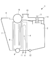
図1および図2に示すように、本実施形態に係るVOCガス処理システム100が備える舶用ボイラ1は、火炉2と、バーナ3と、VOCガス供給部60(揮発性ガス供給部)と、蒸発管群6(熱交換器群)と、ガス出口8(排出部)と、制御装置50(制御部)とを備える。
図2に示す舶用ボイラ1において、火炉2の上部に設置された風箱14内に複数のバーナ3が設置される。バーナ3は、主燃料ライン35を介して供給されるボイラ主燃料(燃焼用燃料)と、空気ダクト13を介して導入される燃焼用空気を含む燃料ガスを火炉2内で燃焼させる。
舶用ボイラ1の運転を制御する制御装置50(制御部)は、ボイラ主燃料のバーナ3への供給量および燃焼用空気のバーナ3への供給量をそれぞれ調整して所定の負荷範囲で舶用ボイラ1を運転するものである。燃焼用空気のバーナ3への供給量は、各種のパラメータに応じて適宜調整すればよい。例えば、ガス出口8から排出される排気ガスに含まれる酸素濃度を酸素濃度センサ(不図示)により検出し、検出した酸素濃度に応じて燃焼用空気のバーナ3への供給量を調整してもよい。
燃料遮断弁41は、制御装置50によって開閉される弁であり、ボイラ主燃料(例えば、HFO(Heavy Fuel Oil:重質燃料油)、MDO(Marine Diesel Oil:船舶用ディーゼル油)、メタン等)を、主燃料ライン35を介して舶用ボイラ1に供給する場合に開状態となる。
燃料制御弁30は、制御装置50によって開度が調整される弁であり、その開度によってバーナ3に供給されるボイラ主燃料の流量を調整する。
流量計60aは、VOCガスライン34を介して流入するVOCガスの流量を計測する計測器であり、計測した流量を制御装置50に通知するようになっている。
遮断弁60dは、VOCガスライン34から供給されるVOCガスをバーナ3に供給するか否かを切り換えるために用いられる弁である。制御装置50は、VOCガスが流通する流路の外部に設置されたガス検知器70が、所定濃度以上の揮発性有機化合物を検知した場合に、遮断弁60dを遮断状態に切り換える。これにより、VOCガスが流路から漏れる不具合が発生する場合に、揮発性有機化合物が更に漏れないようにすることができる。なお、ガス検知器70として、例えば、揮発性有機化合物の主成分であるブタンの濃度を検知する検知器を用いることができる。
舶用ボイラ1は、更に蒸気ドラム10で発生し、荷役用タービンに導かれる蒸気の流量を測定するための差圧発信器91を備えている。差圧発信器91はオリフィス92の上流側と下流側の圧力の差分(差圧)を検知することによりオリフィス92を通過する蒸気の流量を計測する計測器である。差圧発信器91が計測した蒸気の流量は、制御装置50に通知される。
原油タンク22は、原油が貯蔵されるタンクであり、原油から揮発した揮発性有機化合物の発火を防止するために、内部にイナートガスが封入されている。イナートガスとは、例えば、CO2やN2等の不活性ガスである。原油タンク22内の上方は、揮発性有機化合物とイナートガスが混合したVOCガスによって満たされている。原油タンク22内のVOCガスは、制御装置50により遮断弁44が開状態に制御されることにより、VOCガスフィルタ27に導かれる。
VOCガスフィルタ27によって異物が除去されたVOCガスは、ブロワー28によってVOCガスライン34を経由して舶用ボイラ1に導かれる。
図3に示す各工程は、制御装置50が記憶部(図示略)から制御プログラムを読み出して実行することにより行われる。
図3の説明にあたっては、図4を参照する。図4は、図1に示す舶用ボイラにおけるボイラ負荷に対するVOCガスの炉内滞留時間および火炉出口温度を示すグラフである。炉内滞留時間とは、バーナ3から火炉2内に流入したVOCガスが火炉出口(つまり熱交換器群入口)に至るまでに要する経過時間のことである。また、火炉出口温度とは、火炉2の下流側かつ熱交換器群の上流側付近の温度のことである。
ステップS302で、制御装置50は、設定部51を介して、舶用ボイラ1の操作者によりVOC処理モードが設定されているか否かを判定する。ここで、VOC処理モード(制限運転モード)とは、イナートガスに含まれるVOC濃度が低濃度であり、VOCガスを確実に酸化処理したい場合に操作者により設定される運転モードである。操作者は、例えば、ガス分析計60bにより計測される揮発性有機化合物の濃度が低濃度である場合に、設定部51を介してVOC処理モードを設定する。
ステップS302でVOC処理モードが設定されていると判定された場合、制御装置50はステップS303に処理を進め、そうでなければステップS304に処理を進める。
また、図4に示すように、火炉出口温度は、ボイラ負荷が大きくなるほど高くなり、ボイラ負荷が小さくなるほど低くなる傾向にある。これは、ボイラ負荷が大きくなるにつれてボイラ主燃料と燃焼用空気の流量が増加し、その結果として燃焼により発生する燃焼ガスの温度が上昇するからである。
従って、ボイラ負荷が約20%~約50%の範囲となるように舶用ボイラ1の運転を制限することにより、低濃度のVOCガスを確実に酸化処理して無害化することができる。図4に示す例では、ボイラ負荷が20%以上かつ50%以下の範囲がVOC処理モードにて制限される制限負荷範囲となる。
ステップS304およびステップS305を実行することにより、図3に示される舶用ボイラ1の運転が終了し、再びステップS301の処理を開始する。
本実施形態の舶用ボイラ1によれば、原油タンク22内で発生する揮発性有機化合物を含むVOCガス(揮発性ガス)は、バーナ3による燃料ガスの燃焼により加熱された火炉2内に供給され、熱交換器群を通過した後にガス出口8(排出部)から排出される。舶用ボイラ1の運転を制御する制御装置50(制御部)は、燃焼用燃料のバーナ3への供給量および燃焼用空気のバーナ3への供給量をそれぞれ調整して所定の負荷範囲(0~100%)で舶用ボイラ1を運転するものであるが、VOC処理モードを実行する際は所定の負荷範囲より制限された制限負荷範囲内(例えば、20%以上かつ50%以下)で舶用ボイラ1を運転する。制御装置50がVOC処理モードを実行する場合、火炉2に流入して火炉出口に導かれるVOCガスは、所定時間(例えば、約0.5秒)以上火炉2内に滞留し、かつ所定温度(例えば、約800℃)以上に維持される。この所定時間および所定温度をVOCガスの酸化処理が十分に行われる値とすることにより、燃焼が困難な低濃度VOCガスであっても火炉内で十分に酸化処理された状態でガス出口8から排出される。
このようにすることで、船内の蒸気需要が少ない場合であっても、主燃料の消費量を抑制しつつ、低濃度の揮発性有機化合物を含むVOCガスを確実に酸化処理することが可能な舶用ボイラ1を提供することができる。
このようにすることで、火炉2内に供給されるVOCガスの流量を調整して火炉2内の火炎温度を適切な温度に低下させ、窒素物(NOx)の発生量を少なくすることができる。
このようにすることで、スクラバーで燃焼ガスに含まれる有害物質を除去しつつ燃焼ガスに含まれる不活性ガスを冷却し、再び調整弁に導いて不活性ガスを再利用することができる。
このようにすることで、VOCガスが外部に流出した場合に、その流出を検知して原油タンク22からバーナ3へのVOCガスの供給を遮断し、VOCガスが更に外部に流出することを確実に防止することができる。
このようにすることで、VOCガスの濃度が高く、かつバーナ3による燃料ガスの燃焼が行われている場合に、VOCガスをバーナ3にて燃焼させることができる。
前述した実施形態では、舶用ボイラ1は、火炉2内の温度を計測する温度検出器80を備えるものとしたが、他の態様であってもよい。例えば、舶用ボイラ1に温度検出器80設けずに、舶用ボイラ1の負荷や温度検出器90が検出する排気ガスの温度から火炉2内の温度を算出するようにしてもよい。
2 火炉
3 バーナ
4 フロントバンクチューブ(熱交換器群)
5 過熱器(熱交換器群)
6 蒸発管群(熱交換器群)
8 ガス出口(排出部)
22 原油タンク
24 イナートガスノズル(不活性ガス供給部)
33 イナートガスライン(再循環ライン)
42 制御弁(調整弁)
50 制御装置(制御部)
60 VOCガス供給部(揮発性ガス供給部)
70 ガス検知器(検知部)
100 VOCガス処理システム
Claims (4)
- 火炉と、
燃焼用燃料および燃焼用空気を前記火炉内で燃焼させるバーナと、
原油タンク内で発生する揮発性有機化合物を含む揮発性ガスを前記火炉内に供給する揮発性ガス供給部と、
前記バーナによる燃焼により発生する燃焼ガスを排出する排出部と、
前記燃焼用燃料の前記バーナへの供給量および前記燃焼用空気の前記バーナへの供給量をそれぞれ調整し、所定の負荷範囲で運転制御する制御部とを備え、
前記制御部は、前記揮発性ガス供給部から前記火炉に流入して前記排出部に導かれる前記揮発性ガスが所定温度以上に維持され、かつ所定時間以上前記火炉内に滞留するように、前記所定の負荷範囲より制限された制限負荷範囲で運転する制限運転モードを備える舶用ボイラ。 - 前記原油タンク内に封入される不活性ガスを前記火炉内に供給する不活性ガス供給部と、
前記不活性ガス供給部に供給する前記不活性ガスの流量を調整する調整弁とを備える請求項1に記載の舶用ボイラ。 - 前記揮発性ガスの外部への流出を検知する検知部と、
前記検知部が前記揮発性ガスの外部への流出を検知する場合に、前記原油タンクから前記バーナへの前記揮発性ガスの供給を遮断する遮断弁とを備える請求項1または請求項2に記載の舶用ボイラ。 - 舶用ボイラの運転方法であって、
燃焼用燃料および燃焼用空気を火炉内で燃焼させるバーナへの前記燃焼用燃料の供給量および前記燃焼用空気の供給量をそれぞれ調整し、所定の負荷範囲で運転する第1運転工程と、
原油タンク内で発生する揮発性有機化合物を含む揮発性ガスを前記火炉内に供給する揮発性ガス供給部から前記火炉に流入する前記揮発性ガスが所定温度以上に維持され、かつ所定時間以上前記火炉内に滞留するように、前記所定の負荷範囲より制限された制限負荷範囲で運転する第2運転工程とを備える舶用ボイラの運転方法。
Priority Applications (4)
| Application Number | Priority Date | Filing Date | Title |
|---|---|---|---|
| KR1020157025603A KR101585389B1 (ko) | 2014-02-14 | 2015-02-05 | 선박용 보일러 및 선박용 보일러의 운전방법 |
| EP15749676.1A EP2960577B1 (en) | 2014-02-14 | 2015-02-05 | Marine boiler and method for operating marine boiler |
| CN201580000436.3A CN105074334B (zh) | 2014-02-14 | 2015-02-05 | 船用锅炉及船用锅炉的运行方法 |
| SG11201508037YA SG11201508037YA (en) | 2014-02-14 | 2015-02-05 | Marine boiler and method for operating marine boiler |
Applications Claiming Priority (2)
| Application Number | Priority Date | Filing Date | Title |
|---|---|---|---|
| JP2014026680A JP5916777B2 (ja) | 2014-02-14 | 2014-02-14 | 舶用ボイラおよび舶用ボイラの運転方法 |
| JP2014-026680 | 2014-02-14 |
Publications (1)
| Publication Number | Publication Date |
|---|---|
| WO2015122356A1 true WO2015122356A1 (ja) | 2015-08-20 |
Family
ID=53800103
Family Applications (1)
| Application Number | Title | Priority Date | Filing Date |
|---|---|---|---|
| PCT/JP2015/053279 Ceased WO2015122356A1 (ja) | 2014-02-14 | 2015-02-05 | 舶用ボイラおよび舶用ボイラの運転方法 |
Country Status (6)
| Country | Link |
|---|---|
| EP (1) | EP2960577B1 (ja) |
| JP (1) | JP5916777B2 (ja) |
| KR (1) | KR101585389B1 (ja) |
| CN (1) | CN105074334B (ja) |
| SG (1) | SG11201508037YA (ja) |
| WO (1) | WO2015122356A1 (ja) |
Cited By (2)
| Publication number | Priority date | Publication date | Assignee | Title |
|---|---|---|---|---|
| CN113250861A (zh) * | 2020-02-07 | 2021-08-13 | 南通中集太平洋海洋工程有限公司 | 运输船及其voc燃料供气系统和供气方法 |
| CN113339820A (zh) * | 2021-06-10 | 2021-09-03 | 新疆广汇新能源有限公司 | 一种低温甲醇洗尾气中VOCs的处理方法及其装置 |
Families Citing this family (6)
| Publication number | Priority date | Publication date | Assignee | Title |
|---|---|---|---|---|
| JP6462023B2 (ja) * | 2017-02-27 | 2019-01-30 | 三菱重工業株式会社 | 船舶 |
| JP6957165B2 (ja) * | 2017-02-28 | 2021-11-02 | 三菱重工マリンマシナリ株式会社 | ボイラ及びボイラシステム並びにボイラの運転方法 |
| DE102017222517A1 (de) * | 2017-12-12 | 2019-06-13 | Dürr Systems Ag | Verfahren zur Reinigung von Abgas und Abgasreinigungsvorrichtung |
| JP6995609B2 (ja) * | 2017-12-22 | 2022-01-14 | 三菱重工マリンマシナリ株式会社 | ボイラ |
| KR102538599B1 (ko) * | 2018-04-20 | 2023-05-31 | 대우조선해양 주식회사 | 선박의 휘발성 유기화합물 처리 시스템 |
| JP7152957B2 (ja) * | 2019-01-08 | 2022-10-13 | 三菱重工マリンマシナリ株式会社 | 舶用ボイラ及び舶用ボイラの改造方法 |
Citations (6)
| Publication number | Priority date | Publication date | Assignee | Title |
|---|---|---|---|---|
| JPS62157887A (ja) * | 1985-12-28 | 1987-07-13 | Mitsubishi Heavy Ind Ltd | 船舶の可燃性蒸発貨物回収利用装置 |
| US5427746A (en) * | 1994-03-08 | 1995-06-27 | W. R. Grace & Co.-Conn. | Flow modification devices for reducing emissions from thermal voc oxidizers |
| WO1997040307A1 (en) * | 1996-04-25 | 1997-10-30 | Den Norske Stats Oljeselskap A/S | Process and system for recovering and storing a light hydrocarbon vapor from crude oil |
| WO1998033026A1 (en) * | 1997-01-29 | 1998-07-30 | Den Norske Stats Oljeselskap A.S | A method of reducing discharge of volatile organic compounds |
| US20120291879A1 (en) * | 2010-01-29 | 2012-11-22 | O'connor Simon Mark | Handling hydrocarbon cargoes |
| WO2013162965A1 (en) * | 2012-04-27 | 2013-10-31 | John Zink Company, Llc | Handling liquid hydrocarbon |
Family Cites Families (5)
| Publication number | Priority date | Publication date | Assignee | Title |
|---|---|---|---|---|
| US4036576A (en) * | 1976-08-11 | 1977-07-19 | The Trane Company | Incineration system for the disposal of a waste gas and method of operation |
| US5215018A (en) * | 1990-06-26 | 1993-06-01 | White Horse Technologies, Inc. | Pollution control apparatus and method for pollution control |
| US6655137B1 (en) * | 2001-06-25 | 2003-12-02 | Amir A. Sardari | Advanced combined cycle co-generation abatement system |
| JP5010425B2 (ja) * | 2007-10-17 | 2012-08-29 | 三菱重工業株式会社 | 再熱ボイラ及び再熱ボイラのガス温度制御方法 |
| IT1399411B1 (it) * | 2009-07-17 | 2013-04-16 | Eltek Spa | Dispositivo di sicurezza contro fughe di gas combustibile per apparati domestici |
-
2014
- 2014-02-14 JP JP2014026680A patent/JP5916777B2/ja active Active
-
2015
- 2015-02-05 KR KR1020157025603A patent/KR101585389B1/ko active Active
- 2015-02-05 SG SG11201508037YA patent/SG11201508037YA/en unknown
- 2015-02-05 WO PCT/JP2015/053279 patent/WO2015122356A1/ja not_active Ceased
- 2015-02-05 CN CN201580000436.3A patent/CN105074334B/zh active Active
- 2015-02-05 EP EP15749676.1A patent/EP2960577B1/en active Active
Patent Citations (6)
| Publication number | Priority date | Publication date | Assignee | Title |
|---|---|---|---|---|
| JPS62157887A (ja) * | 1985-12-28 | 1987-07-13 | Mitsubishi Heavy Ind Ltd | 船舶の可燃性蒸発貨物回収利用装置 |
| US5427746A (en) * | 1994-03-08 | 1995-06-27 | W. R. Grace & Co.-Conn. | Flow modification devices for reducing emissions from thermal voc oxidizers |
| WO1997040307A1 (en) * | 1996-04-25 | 1997-10-30 | Den Norske Stats Oljeselskap A/S | Process and system for recovering and storing a light hydrocarbon vapor from crude oil |
| WO1998033026A1 (en) * | 1997-01-29 | 1998-07-30 | Den Norske Stats Oljeselskap A.S | A method of reducing discharge of volatile organic compounds |
| US20120291879A1 (en) * | 2010-01-29 | 2012-11-22 | O'connor Simon Mark | Handling hydrocarbon cargoes |
| WO2013162965A1 (en) * | 2012-04-27 | 2013-10-31 | John Zink Company, Llc | Handling liquid hydrocarbon |
Cited By (2)
| Publication number | Priority date | Publication date | Assignee | Title |
|---|---|---|---|---|
| CN113250861A (zh) * | 2020-02-07 | 2021-08-13 | 南通中集太平洋海洋工程有限公司 | 运输船及其voc燃料供气系统和供气方法 |
| CN113339820A (zh) * | 2021-06-10 | 2021-09-03 | 新疆广汇新能源有限公司 | 一种低温甲醇洗尾气中VOCs的处理方法及其装置 |
Also Published As
| Publication number | Publication date |
|---|---|
| JP2015152238A (ja) | 2015-08-24 |
| CN105074334A (zh) | 2015-11-18 |
| CN105074334B (zh) | 2016-08-24 |
| EP2960577A4 (en) | 2016-06-29 |
| KR20150119399A (ko) | 2015-10-23 |
| EP2960577B1 (en) | 2018-06-13 |
| SG11201508037YA (en) | 2015-11-27 |
| KR101585389B1 (ko) | 2016-01-13 |
| JP5916777B2 (ja) | 2016-05-11 |
| EP2960577A1 (en) | 2015-12-30 |
Similar Documents
| Publication | Publication Date | Title |
|---|---|---|
| JP5916777B2 (ja) | 舶用ボイラおよび舶用ボイラの運転方法 | |
| JP5265252B2 (ja) | 熱回収蒸気発生器のホットパージ用のシステム及び方法 | |
| KR101851885B1 (ko) | 배기 가스 재순환 시스템 및 그것을 구비한 선박용 보일러, 그리고 배기 가스 재순환 방법 | |
| JP2014005822A (ja) | 排気還流装置 | |
| JP2009031080A (ja) | 有害物質低減システムおよび燃焼装置 | |
| US20130302739A1 (en) | Method and apparatus for controlling operation of oxyfuel combustion boiler | |
| JP6911640B2 (ja) | 水素ガス燃焼バーナーの制御方法 | |
| JP2023072285A (ja) | 燃焼設備 | |
| JP6357701B1 (ja) | 燃焼状態判定システム | |
| KR100807924B1 (ko) | 가스 터빈 설비, 저칼로리 가스 공급 설비 및 그 가스의칼로리 상승 억제 방법 | |
| JP6748697B2 (ja) | 燃焼制御方法 | |
| KR102917935B1 (ko) | 수소 연소기 | |
| KR102917942B1 (ko) | 개도 조절식 수소 연소기 | |
| JP2025167234A (ja) | 燃焼装置 | |
| JP2025158302A (ja) | 燃焼装置、アンモニア評価方法 | |
| JP2011069527A (ja) | ボイラの低NOx燃焼装置及び燃焼方法、並びにボイラ | |
| JP2009198053A (ja) | バーナ制御装置を備えた燃焼炉 | |
| WO2021013756A1 (en) | Mobile degasification system | |
| JP2025040676A (ja) | ボイラ | |
| CN120225808A (zh) | 利用目标气体注入的低NOx燃烧器 | |
| JP5109489B2 (ja) | バーナの制御方法 | |
| JP2023151263A (ja) | 排ガス中のn2o排出量の低減方法およびその装置 | |
| JP2012211764A (ja) | 燃焼装置 | |
| JP5067037B2 (ja) | 燃焼装置 | |
| CN119173723A (zh) | 燃烧设备 |
Legal Events
| Date | Code | Title | Description |
|---|---|---|---|
| WWE | Wipo information: entry into national phase |
Ref document number: 201580000436.3 Country of ref document: CN |
|
| ENP | Entry into the national phase |
Ref document number: 20157025603 Country of ref document: KR Kind code of ref document: A |
|
| WWE | Wipo information: entry into national phase |
Ref document number: 2015749676 Country of ref document: EP |
|
| 121 | Ep: the epo has been informed by wipo that ep was designated in this application |
Ref document number: 15749676 Country of ref document: EP Kind code of ref document: A1 |
|
| NENP | Non-entry into the national phase |
Ref country code: DE |