WO2015122405A1 - 回転電機 - Google Patents
回転電機 Download PDFInfo
- Publication number
- WO2015122405A1 WO2015122405A1 PCT/JP2015/053630 JP2015053630W WO2015122405A1 WO 2015122405 A1 WO2015122405 A1 WO 2015122405A1 JP 2015053630 W JP2015053630 W JP 2015053630W WO 2015122405 A1 WO2015122405 A1 WO 2015122405A1
- Authority
- WO
- WIPO (PCT)
- Prior art keywords
- stator
- housing
- stator core
- inner diameter
- expansion region
- Prior art date
- Legal status (The legal status is an assumption and is not a legal conclusion. Google has not performed a legal analysis and makes no representation as to the accuracy of the status listed.)
- Ceased
Links
Images



Classifications
-
- H—ELECTRICITY
- H02—GENERATION; CONVERSION OR DISTRIBUTION OF ELECTRIC POWER
- H02K—DYNAMO-ELECTRIC MACHINES
- H02K1/00—Details of the magnetic circuit
- H02K1/06—Details of the magnetic circuit characterised by the shape, form or construction
- H02K1/12—Stationary parts of the magnetic circuit
- H02K1/18—Means for mounting or fastening magnetic stationary parts on to, or to, the stator structures
- H02K1/185—Means for mounting or fastening magnetic stationary parts on to, or to, the stator structures to outer stators
-
- F—MECHANICAL ENGINEERING; LIGHTING; HEATING; WEAPONS; BLASTING
- F02—COMBUSTION ENGINES; HOT-GAS OR COMBUSTION-PRODUCT ENGINE PLANTS
- F02B—INTERNAL-COMBUSTION PISTON ENGINES; COMBUSTION ENGINES IN GENERAL
- F02B39/00—Component parts, details, or accessories relating to, driven charging or scavenging pumps, not provided for in groups F02B33/00 - F02B37/00
- F02B39/02—Drives of pumps; Varying pump drive gear ratio
- F02B39/08—Non-mechanical drives, e.g. fluid drives having variable gear ratio
- F02B39/10—Non-mechanical drives, e.g. fluid drives having variable gear ratio electric
-
- H—ELECTRICITY
- H02—GENERATION; CONVERSION OR DISTRIBUTION OF ELECTRIC POWER
- H02K—DYNAMO-ELECTRIC MACHINES
- H02K5/00—Casings; Enclosures; Supports
- H02K5/04—Casings or enclosures characterised by the shape, form or construction thereof
- H02K5/18—Casings or enclosures characterised by the shape, form or construction thereof with ribs or fins for improving heat transfer
-
- F—MECHANICAL ENGINEERING; LIGHTING; HEATING; WEAPONS; BLASTING
- F02—COMBUSTION ENGINES; HOT-GAS OR COMBUSTION-PRODUCT ENGINE PLANTS
- F02B—INTERNAL-COMBUSTION PISTON ENGINES; COMBUSTION ENGINES IN GENERAL
- F02B37/00—Engines characterised by provision of pumps driven at least for part of the time by exhaust
- F02B37/04—Engines with exhaust drive and other drive of pumps, e.g. with exhaust-driven pump and mechanically-driven second pump
-
- H—ELECTRICITY
- H02—GENERATION; CONVERSION OR DISTRIBUTION OF ELECTRIC POWER
- H02K—DYNAMO-ELECTRIC MACHINES
- H02K2213/00—Specific aspects, not otherwise provided for and not covered by codes H02K2201/00 - H02K2211/00
- H02K2213/03—Machines characterised by numerical values, ranges, mathematical expressions or similar information
Definitions
- This invention relates to a rotating electrical machine.
- An electric turbocharger mounted on a vehicle has a rotating electric machine, that is, an electric motor for driving a compressor.
- the electric motor 112 of the conventional turbocharger 110 includes a rotor 113 and a stator 114 facing each other inside a housing 117.
- the stator 114 includes a stator core 114a and stator coils 114b provided at both ends of the stator core 114a.
- the stator core 114a of the stator 114 is formed of a laminated steel plate in which a plurality of thin steel plates S are stacked.
- An insulation distance A is set between the stator core 114a and the stator coil 114b.
- stator core 114a of the stator 114 is fixed to the housing 117 by shrink fitting.
- shrink fitting means that the housing 117 is thermally expanded to expand the inner diameter, the stator core 114a of the stator 114 at room temperature is assembled at a predetermined position, and then the temperature of the housing 117 is returned to room temperature to reduce the inner diameter. In this method, the position 114 is fixed.
- the stator core 114a of the shrink-fitted stator 114 receives a tightening force F 'from the housing 117 when the inner diameter of the housing 117 contracts.
- the steel plate S at the end of the laminated steel plate of the stator core 114a of the stator 114 may be deformed so as to roll away from the adjacent steel plate S.
- the housing 117 is made of aluminum for weight reduction, and since the operating temperature range is wide, the tightening force F ′ of the housing 117 is low.
- the possibility of deformation of the steel sheet S becomes higher.
- the electric motor 112 used in the electric turbocharger 110 has a very high rotational speed, the laminated steel sheet is thinner than usual in order to reduce eddy current loss. The deformation of is particularly noticeable.
- the distance B between the rolled up steel plate S and the stator coil 114b is smaller than the insulation distance A originally set between the stator core 114a and the stator coil 114b of the stator 114. turn into.
- the distance B between the steel plate S and the stator coil 114b is smaller than the set insulation distance A, there is a risk of electrical insulation being broken and short-circuited when a voltage is applied.
- the present invention has been made to solve such a problem, and an object thereof is to provide a rotating electrical machine that can prevent deformation of a laminated steel sheet of a stator core with a simple structure.
- a rotating electrical machine is attached to a housing, a rotating shaft that is rotatably supported by the housing, and fixed to the rotating shaft, and is accommodated in the inside of the housing.
- a stator that is fixed to the casing and is provided on the radially outer side of the rotor so as to face the rotor, and the stator includes a plurality of layers stacked in the axial direction of the rotating shaft.
- the stator core is formed of a steel plate, and the stator core is fixedly attached to a stator mounting surface provided on the inner peripheral surface of the casing.
- the stator core is adjacent to the stator mounting surface on the inner peripheral surface of the casing.
- An inner diameter expansion region formed so as not to contact the stator core is provided at a position opposite to the end portion of the stator, the inner diameter expansion region is adjacent to the stator mounting surface, and the diameter of the inner diameter expansion region is equal to that of the stator mounting surface. Larger than the diameter Accordingly, since the end portion of the stator core does not contact the housing, no force is applied to the end portion of the stator core even when the housing contracts.
- region which concerns on the rotary electric machine which concerns on this invention may have an inclined surface which inclines in the axial direction of a rotating shaft.
- the length of the inner diameter expansion region in the axial direction of the rotating shaft may be equal to or longer than the length of 10 steel plates stacked.
- the inner diameter expansion region may be provided at positions facing the end portions at both ends of the stator core.
- the length of the inner diameter expansion region in the axial direction of the rotating shaft may be increased as the outer diameter of the stator core is increased.
- the rotating electrical machine it is possible to prevent deformation of the laminated steel sheet of the stator core with a simple structure.
- FIG. 3 is an enlarged view of the vicinity of a fixed portion between a housing and a stator core in the rotating electrical machine shown in FIG. 2.
- FIG. 3 is an enlarged view of the vicinity of an end of a stator core in the rotating electrical machine shown in FIG. 2.
- FIG. 6B is an enlarged view showing a state of the stator core when the housing tightening force is applied in the rotating electric machine shown in FIG. 6A.
- FIG. FIG. 1 shows a supercharging system 100 including an electric turbocharger 10 having a rotary electric machine, that is, an electric motor 12 according to this embodiment.
- an exhaust passage 2 through which exhaust gas flows and an intake passage 3 through which intake air flows are connected to an engine 30 of the vehicle.
- a turbine portion 42 of an exhaust turbocharger 40 is provided in the exhaust passage 2 .
- the intake passage 3 is provided with a compressor section 41 of an exhaust turbocharger 40.
- the compressor unit 41 and the turbine unit 42 are integrally connected, and the turbine unit 42 is driven to rotate by the pressure of the exhaust gas, and the compressor unit 41 also rotates. That is, the exhaust turbocharger 40 is driven by the energy of the exhaust gas of the engine 30 to compress the intake air.
- a first intercooler 70, an electric turbocharger 10, and a second intercooler 80 are sequentially provided downstream of the exhaust turbocharger 40.
- the intake passage 3 and the exhaust turbocharger 40 and the electric turbocharger 10 provided in the intake passage 3 constitute a supercharging system 100 for compressing intake air flowing into the engine 30.
- the electric turbocharger 10 includes a compressor 11 provided in the intake passage 3 and an electric motor 12 connected to the compressor 11. That is, the electric turbocharger 10 is driven by the electric motor 12 to compress the intake air.
- the ECU 60 is electrically connected to the engine 30 and the electric turbocharger 10, respectively.
- the intake passage 3 is connected to a bypass passage 5 that bypasses the electric turbocharger 10.
- one end of the bypass flow path 5 is connected to a first branch point 3 a provided downstream of the first intercooler 70 and upstream of the electric turbocharger 10.
- the other end of the bypass flow path 5 is connected to a second branch point 3 b provided downstream of the electric turbocharger 10 and upstream of the second intercooler 80.
- a check valve 50 is provided in the bypass flow path 5.
- the electric motor 12 of the electric turbocharger 10 includes an aluminum housing 17.
- a plurality of heat dissipating fins 18 are formed on the outer peripheral surface of the housing 17.
- a housing space 15 having a substantially cylindrical shape is formed inside the housing 17.
- a rotation shaft 16 extends along the central axis of the housing 17 in the accommodation space 15. The rotating shaft 16 is rotatably supported by the housing 17 via bearings 19a and 19b.
- the axial direction of the rotary shaft 16 the right side on the paper surface in FIG. 2 is defined as the X direction, and the left side on the paper surface in FIG.
- the compressor 11 is fixedly attached to a portion of the rotary shaft 16 that protrudes outside the housing 17 so as to be integrally rotatable.
- the housing 17 constitutes a housing.
- the rotor 13 is fixedly attached to the rotary shaft 16. That is, the rotor 13 is accommodated in the housing 17.
- a stator receiving portion 37 that is a belt-like protruding portion is formed on the inner peripheral surface of the housing 17 facing the accommodation space 15.
- the stator receiving part 37 has a stator mounting surface 37a which is a cylindrical curved surface.
- An inclined surface 37c is formed at the end portion in the X direction of the stator receiving portion 37 so as to extend radially outward toward the X direction side, adjacent to the stator mounting surface 37a. That is, the inclined surface 37 c is inclined with respect to the axial direction of the rotary shaft 16. And as shown in FIG.
- the boundary of the stator attachment surface 37a and the inclined surface 37c comprises the edge part 37e in the X 'direction of the inclined surface 37c. Moreover, the edge part in the X direction of the inclined surface 37c is 37f.
- a flange 37d that protrudes radially inward is formed adjacent to the stator attachment surface 37a at the end in the X ′ direction of the stator receiving portion 37.
- a substantially cylindrical stator core 14a is fixed to the stator mounting surface 37a of the stator receiving portion 37 by shrink fitting.
- the stator core 14a is formed by laminating a plurality of steel plates St each having a uniform thickness t in the axial direction of the rotating shaft (see FIG. 4).
- the outer peripheral surface of the stator core 14a is a cylindrical curved surface. Further, the end portion in the X ′ direction of the stator core 14 a abuts on the flange 37 d, and the stator core 14 a is provided so as to face the rotor 13 on the outer side of the rotor 13. Further, stator coils 14b are attached to both ends of the stator core 14a.
- the stator core 14 a and the stator coil 14 b constitute the stator 14.
- the rotor 13 constitutes a rotor
- the stator 14 constitutes a stator.
- the flange 37d functions as a stopper that defines the position of the stator 14 when the stator 14 is incorporated into the housing 17 from the X direction side.
- the flange 37d since the flange 37d is in contact with the steel plate St at the end in the X ′ direction of the stator core 14a, the flange 37d prevents the steel plate St from rising at the end in the X ′ direction of the stator core 14a.
- a line corresponding to a position where the end surface in the X direction of the stator core 14a extends radially outward is defined as an extended portion boundary line 37g.
- a region between the end portion 37e of the inclined surface 37c and the extended portion boundary line 37g constitutes an inner diameter extended region 37b.
- the length of the stator core 14a in the axial direction of the rotating shaft 16 is L1, and the length of the stator mounting surface 37a is L2.
- the length L3 of the inner diameter expansion region 37b is longer than the length 10t in which ten steel plates St are stacked side by side.
- a portion in which ten steel plates are stacked and arranged from an end portion in the X direction of the stator core 14a is defined as an end portion 14c of the stator core 14a.
- the inner diameter expansion region 37b on the inner peripheral surface of the housing 17 is formed at a position facing the end portion 14c of the stator core 14a.
- the length L2 of the stator mounting surface 37a is set to a certain length that allows the stator 14 to be fixed to the housing 17 in the entire operating temperature range of the electric turbocharger 10.
- the outer diameter of the stator core 14a is ⁇ D1.
- ⁇ D1 is around 60 mm. Since the stator core 14a is fixed to the stator receiving portion 37 by shrink fitting, the diameter of the stator mounting surface 37a of the stator receiving portion 37 is substantially equal to the outer diameter of the stator core 14a.
- the diameter of the mounting surface 37a is also ⁇ D1.
- a portion other than the stator receiving portion 37 on the inner wall of the housing 17, that is, a portion extending in the X direction from the end portion 37f of the inclined surface 37c and a portion extending in the X ′ direction from the flange 37d form a cylindrical curved surface,
- the size of the inner diameter is ⁇ D2.
- the diameter ⁇ D2 is larger than the diameter ⁇ D1. That is, since the size of the inner diameter of the housing 17 is expanded from ⁇ D1 to ⁇ D2 in the X direction in the inner diameter expansion region 37b, the diameter of the inner diameter expansion region 37b is larger than the diameter of the stator mounting surface 37a. At the same time, since the diameter of the inner diameter expansion region 37b is larger than the diameter of the stator core 14a, the inner diameter expansion region 37b is formed so as not to contact the stator core 14a.
- the flow of the intake air in the supercharging system 100 will be described.
- the turbine portion 42 of the exhaust turbocharger 40 is rotationally driven by the pressure of the exhaust gas flowing into the exhaust passage 2.
- the compressor unit 41 of the exhaust turbocharger 40 is driven, and the intake air flowing through the intake passage 3 is compressed by the compressor unit 41.
- the compressed intake air is cooled by the first intercooler 70.
- the ECU 60 reads the rotational speed of the engine 30. Then, the ECU 60 determines whether or not the engine 30 is rotating at a high speed.
- the electric motor 12 of the electric turbocharger 10 is maintained in a stopped state. To do.
- the compressor 11 of the electric turbocharger 10 that is not rotationally driven becomes a resistance against the flow of intake air in the intake passage 3. Therefore, the intake air flows into the bypass channel 5 after passing through the first branch point 3a.
- the check valve 50 is opened by the pressure of the intake air, and the intake air flows through the bypass flow path 5 and flows again into the intake passage 3 via the second branch point 3b. It passes through and flows into the engine 30.
- the turbine portion 42 of the exhaust turbocharger 40 cannot obtain sufficient energy from the exhaust gas. Therefore, the compressor unit 41 of the exhaust turbocharger 40 cannot sufficiently increase the supercharging pressure of the intake air.
- the ECU 60 determines whether or not the engine 30 is rotating at a predetermined speed or higher, and when the engine 30 is rotating at a speed lower than the predetermined speed, the electric motor 12 of the electric turbocharger 10 is rotationally driven.
- the electric turbocharger 40 may be driven because the turbine portion 42 of the exhaust turbocharger 40 cannot obtain sufficient energy from the exhaust gas immediately after the start.
- a three-phase alternating current flows from the storage battery (not shown) to the stator coil 14b via the inverter (not shown), and a rotating magnetic field is generated between the stator 14 and the rotor 13, thereby rotating.
- the shaft 16 rotates with the compressor 11 (see FIG. 2). Therefore, the intake air of the intake passage 3 that has passed through the compressor portion 41 of the exhaust turbocharger 40 without being sufficiently compressed passes through the first intercooler 70 and the first branch point 3a, and is then compressed by the compressor 11 of the electric turbocharger 10. Compressed.
- the check valve 50 provided in the bypass flow path 5 is closed, and the intake air does not flow through the bypass flow path 5.
- the intake air compressed by the electric turbocharger 10 passes through the second branch point 3b, is cooled by the second intercooler 80, and then flows into the engine 30.
- the inner diameter expansion region 37b provided on the inner peripheral surface of the housing 17 at a position facing the end portion 14c on the stator core 14a has a diameter larger than that of the stator mounting surface 37a. Is large and does not contact the stator core 14a. Therefore, even if the stator core 14a receives the tightening force F due to the shrinkage of the housing 17 after baking, the tightening force F is not directly applied to the steel plate St itself of the end portion 14c of the stator core 14a. Therefore, it is possible to prevent the deformation of the steel plate St at the end portion 14c of the stator core 14a with a simple structure without changing the shape of the stator core 14a.
- the method of fixing the stator core 14a to the inner peripheral surface of the housing 17 is shrink fitting, parts such as fixing bolts are unnecessary, and the manufacturing cost can be reduced correspondingly.
- the electric turbocharger 10 itself can be reduced in size.
- the inner diameter expansion region 37 b has an inclined surface 37 c that is inclined with respect to the axial direction of the rotary shaft 16.
- the inclined surface 37c abuts against the end of the stator core 14a, so that the stator core 14a is more smoothly fixed to the stator. It is guided inside the mounting surface 37a. Further, since the length L3 of the inner diameter expansion region is not less than the length 10t obtained by laminating 10 steel plates St, the deformation of the steel plate St at the end of the stator core 14a can be prevented more reliably.
- FIG. FIG. 5 shows a configuration of an electric turbocharger 20 having a rotary electric machine, that is, an electric motor 22 according to an embodiment of the present invention.
- the electric turbocharger 20 according to this embodiment is obtained by replacing the housing 17 of the electric turbocharger 10 according to the first embodiment with a housing 27 including a stator receiving portion 47 in which two inclined surfaces 47c and 47h are formed. is there.
- the same reference numerals as those in FIGS. 1 to 4 are the same or similar components, and thus detailed description thereof is omitted.
- the electric motor 22 of the electric turbocharger 20 includes an aluminum housing 27.
- a plurality of heat radiation fins 28 are formed on the outer peripheral surface of the housing 27.
- a housing space 15 having a substantially cylindrical shape is formed inside the housing 27 as in the inside of the housing 17 of the electric turbocharger 10 according to the first embodiment.
- a stator receiving portion 47 which is a belt-like protruding portion, is formed on the inner peripheral surface of the housing 27 facing the housing space 15.
- the stator receiving portion 47 has a stator mounting surface 47a which is a cylindrical curved surface.
- An inclined surface 47c is formed at an end portion in the X direction of the stator receiving portion 47 so as to extend radially outward toward the X direction side, adjacent to the stator mounting surface 47a.
- the boundary between the stator mounting surface 47a and the inclined surface 47c constitutes an end portion 47e in the X 'direction of the inclined surface 47c.
- the edge part in the X direction of the inclined surface 47c is 47f.
- an inclined surface 47h is formed at an end portion in the X ′ direction of the stator receiving portion 47 so as to spread radially outward toward the X ′ direction side, adjacent to the stator mounting surface 47a.
- the boundary between the stator mounting surface 47a and the inclined surface 47h constitutes an end portion 47k in the X direction of the inclined surface 47h.
- the end portion of the inclined surface 47c in the X ′ direction is 47j.
- the stator core 14a is fixed to the stator attachment surface 47a of the stator receiving portion 47 by shrink fitting.
- a line corresponding to a position where the end surface in the X direction of the stator core 14a extends radially outward on the inner peripheral surface of the housing 27 facing the accommodation space 15 is defined as a first extended portion boundary line 47g.
- a region between the end portion 47e of the inclined surface 47c and the first expanded portion boundary line 47g constitutes a first inner diameter expanded region 47b.
- a line corresponding to a position where the end surface in the X ′ direction of the stator core 14a extends radially outward is defined as a second extended portion boundary line 47m.
- a region between the end portion 47k of the inclined surface 47h and the second extended portion boundary line 47m constitutes a second inner diameter extended region 47i.
- the length of the stator mounting surface 47a in the axial direction of the rotary shaft 16 is L4.
- the lengths of the first inner diameter expansion region 47b and the second inner diameter expansion region 47i in the axial direction of the rotary shaft 16 are each L5.
- the length L5 of the first inner diameter expansion region 47b and the second inner diameter expansion region 47i is longer than the length 10t in which ten steel plates St are stacked side by side.
- the end portion 14d is also a portion in which ten steel plates are stacked side by side from the end portion in the X ′ direction of the stator core 14a.
- first inner diameter expansion region 47b and the second inner diameter expansion region 47i on the inner peripheral surface of the housing 17 are formed at positions facing the end portions 14c and 14d at both ends of the stator core 14a, respectively.
- the length L4 of the stator mounting surface 47a is set to a certain length that allows the stator 14 to be fixed to the housing 27 in the entire operating temperature range of the electric turbocharger 20.
- the diameter of the stator mounting surface 47a is ⁇ D1 similarly to the diameter of the stator mounting surface 37a according to the first embodiment.
- portions other than the stator receiving portion 37 that is, a portion extending in the X direction from the end portion 47f of the inclined surface 47c and a portion extending in the X ′ direction from the end portion 47j of the inclined surface 47h are cylindrical.
- the inner diameter is ⁇ D3.
- the diameter ⁇ D3 is larger than the diameter ⁇ D1. That is, the size of the inner diameter of the housing 27 expands in the X direction in the first inner diameter expansion region 47b and also expands in the X ′ direction in the second inner diameter expansion region 47i.
- the diameters of the first inner diameter expansion region 47b and the second inner diameter expansion region 47i are larger than the diameter of the stator attachment surface 47a.
- the first inner diameter expansion area 47b and the second inner diameter expansion area 47i are larger in diameter than the stator core 14a, so that the first inner diameter expansion area 47b and the second expansion area 47i do not contact the stator core 14a. Is formed.
- the first inner diameter expansion region 47b and the second inner diameter expansion region 47i are provided at positions facing the end portions 14c and 14d at both ends of the stator core 14a. Yes. Therefore, deformation of the steel plates St of the end portions 14c and 14d at both ends of the stator core 14a can be prevented.
- the length L3 of the inner diameter expansion region 37b in the axial direction of the rotating shaft 16 may be changed according to the outer diameter ⁇ D1 of the stator core 14a. That is, the longer the outer diameter of the stator core 14a, the longer the length L3 of the inner diameter expansion region 37b. The smaller the outer diameter of the stator core 14a, the shorter the length L3 of the inner diameter expansion region 37b. Specifically, when the outer diameter ⁇ D1 of the stator core 14a is around 60 mm, the length L3 of the inner diameter expansion region 37b is approximately the same as the length 10t obtained by laminating 10 steel plates St, but ⁇ D1 is further increased.
- the length L3 of the inner diameter expansion region 37b also increases in accordance with ⁇ D1. Thereby, the roll-up due to the deformation of the steel plate St is suppressed while the fastening force F from the housing 17 is secured.
Landscapes
- Engineering & Computer Science (AREA)
- Power Engineering (AREA)
- Physics & Mathematics (AREA)
- Thermal Sciences (AREA)
- Chemical & Material Sciences (AREA)
- Combustion & Propulsion (AREA)
- Mechanical Engineering (AREA)
- General Engineering & Computer Science (AREA)
- Iron Core Of Rotating Electric Machines (AREA)
- Supercharger (AREA)
Abstract
電動モータ(12)は、ハウジング(17)と、ハウジング(17)に回転可能に支持される回転シャフト(16)と、回転シャフト(16)に固定されるロータ(13)と、ハウジング(17)に固定され、ロータ(13)の径方向外側にロータ(13)と対向して設けられるステータ(14)とを備える。ステータ(14)は複数の鋼板(St)が積層されて形成されるステータコア(14a)を有し、ステータコア(14a)はハウジング(17)の内周面の固定子取付面(37a)に固定される。ハウジング(17)の内周面には、固定子取付面(37a)に隣接し、ステータコア(14a)の端部部分に対応する位置に内径拡張領域(37b)が設けられる。内径拡張領域(37b)の径は固定子取付面(37a)の径よりも大きく、ステータコア(14a)に当接しない。これによって、簡易な構造でステータコア(14a)の積層鋼板(St)の変形を防止できる。
Description
この発明は、回転電機に関する。
車両に搭載される電動ターボチャージャは、コンプレッサを駆動するための回転電機すなわち電動モータを有している。図6Aに示すように、従来のターボチャージャ110の電動モータ112は、ハウジング117の内部に、互いに対向するロータ113とステータ114とを有する。ステータ114はステータコア114aとステータコア114aの両端に設けられたステータコイル114bを備える。なお、図6Bに示すように、ステータ114のステータコア114aは、複数の薄い鋼板Sが重ね合わせられた積層鋼板によって形成されている。また、ステータコア114aとステータコイル114bとの間には絶縁距離Aが設定されている。さらに、ステータ114のステータコア114aはハウジング117に焼き嵌めによって固定される。なお、「焼き嵌め」とは、ハウジング117を熱膨張させて内径を広げ、常温のステータ114のステータコア114aを所定の位置に組み込んだ後、ハウジング117の温度を常温に戻して内径を縮め、ステータ114の位置を固定する方法である。
ここで、焼き嵌めされたステータ114のステータコア114aは、ハウジング117の内径が縮む際に、ハウジング117からの締め付け力F’を受ける。そのため、図6Bに示すように、ステータ114のステータコア114aの積層鋼板の端部の鋼板Sが隣り合う鋼板Sから離れて捲れ上がるように変形してしまうことがあった。特に、電動ターボチャージャ110は車両に搭載するものであるので、軽量化のためにハウジング117はアルミ製となっており、また、使用温度範囲が広いため、ハウジング117の締め付け力F’は低温時に高くなり、鋼板Sの変形の可能性はより高くなる。またさらに、電動ターボチャージャ110に使用される電動モータ112は回転数が非常に高いため、渦電流損失を低減するために積層鋼板の鋼板は通常よりも薄いものが使用されており、捲り上がり等の変形は特に顕著となる。
このように鋼板Sが変形すると、ステータ114のステータコア114aとステータコイル114bとの間に本来設定されている絶縁距離Aよりも、捲れ上がった鋼板Sとステータコイル114bとの距離Bの方が小さくなってしまう。鋼板Sとステータコイル114bとの距離Bが、設定された絶縁距離Aよりも小さい場合、電圧印加時に電気絶縁が破壊されてショートする危険性がある。
そこで、このような問題に対処するため、特許文献1に記載される電動機では、特許文献1の図3~5に示すように、ステータコアの積層鋼板の径を両端部分のみ小さくすることで、端部の鋼板が変形して捲れ上がることを防いでいる。
しかしながら、特許文献1に記載される電動機の場合、コアの両端部以外の積層鋼板においても、ハウジングと接触している箇所では依然としてハウジングの締め付け力による鋼板の変形の可能性がある。コアの端部以外の箇所であっても、ステータコイルに近接する鋼板が捲れ上がった場合、鋼板とステータコイルとの絶縁距離を正確に確保するのは困難である。また、特許文献1の電動機では、ステータのコアの両端部のみ径を小さくするために新たにステータコア用の型を作る必要があり、製造コストが上がってしまうという問題もある。
この発明は、このような問題を解決するためになされ、簡易な構造でステータコアの積層鋼板の変形を防止することができる回転電機を提供することを目的とする。
上記の課題を解決するために、この発明に係る回転電機は、筐体と、筐体に回転可能に支持される回転シャフトと、回転シャフトに固定されて取り付けられるとともに、筐体の内部に収容される回転子と、筐体に固定されるとともに、回転子の径方向外側に回転子と対向して設けられる固定子とを備え、固定子は、回転シャフトの軸方向において積層された複数の鋼板によって形成されるステータコアを有し、ステータコアは筐体の内周面に設けられる固定子取付面に固定して取付けられ、筐体の内周面には、固定子取付面に隣接し、ステータコアの端部部分に対向する位置に、ステータコアに当接しないように形成される内径拡張領域が設けられ、内径拡張領域は固定子取付面に隣接し、内径拡張領域の径は固定子取付面の径よりも大きい。
これにより、ステータコアの端部部分はハウジングと接触しないため、ハウジングが収縮する際にもステータコアの端部部分には力がかからない。
これにより、ステータコアの端部部分はハウジングと接触しないため、ハウジングが収縮する際にもステータコアの端部部分には力がかからない。
また、この発明に係る回転電機に係る内径拡張領域は、回転シャフトの軸方向において傾斜する傾斜面を有してもよい。
また、回転シャフトの軸方向における内径拡張領域の長さは、鋼板を10枚積層した長さ以上であってもよい。
さらに、内径拡張領域は、ステータコアの両端の端部部分に対向する位置にそれぞれ設けられてもよい。
さらにまた、ステータコアの外径が大きくなる程、回転シャフトの軸方向における内径拡張領域の長さは長くなってもよい。
また、回転シャフトの軸方向における内径拡張領域の長さは、鋼板を10枚積層した長さ以上であってもよい。
さらに、内径拡張領域は、ステータコアの両端の端部部分に対向する位置にそれぞれ設けられてもよい。
さらにまた、ステータコアの外径が大きくなる程、回転シャフトの軸方向における内径拡張領域の長さは長くなってもよい。
この発明に係る回転電機によれば、簡易な構造でステータコアの積層鋼板の変形を防止することができる。
以下、この発明の実施の形態について添付図面に基づいて説明する。
実施の形態1.
この実施の形態に係る回転電機すなわち電動モータ12を有する電動ターボチャージャ10を含んだ過給システム100を図1に示す。
図1に示すように、車両のエンジン30には、排気ガスが流通する排気通路2及び吸入空気が流通する吸気通路3が接続されている。排気通路2には、排気ターボチャージャ40のタービン部42が設けられている。一方、吸気通路3には排気ターボチャージャ40のコンプレッサ部41が設けられている。排気ターボチャージャ40において、コンプレッサ部41とタービン部42とは一体的に接続し、排気ガスの圧力によってタービン部42が回転駆動されるとともにコンプレッサ部41も回転する。すなわち、排気ターボチャージャ40はエンジン30の排気ガスのエネルギーによって駆動されて吸入空気を圧縮する。また、吸気通路3において、排気ターボチャージャ40の下流には順次、第一インタークーラ70、電動ターボチャージャ10及び第二インタークーラ80が設けられている。
ここで、吸気通路3並びに吸気通路3に設けられた排気ターボチャージャ40及び電動ターボチャージャ10は、エンジン30に流入する吸入空気を圧縮するための過給システム100を構成する。
実施の形態1.
この実施の形態に係る回転電機すなわち電動モータ12を有する電動ターボチャージャ10を含んだ過給システム100を図1に示す。
図1に示すように、車両のエンジン30には、排気ガスが流通する排気通路2及び吸入空気が流通する吸気通路3が接続されている。排気通路2には、排気ターボチャージャ40のタービン部42が設けられている。一方、吸気通路3には排気ターボチャージャ40のコンプレッサ部41が設けられている。排気ターボチャージャ40において、コンプレッサ部41とタービン部42とは一体的に接続し、排気ガスの圧力によってタービン部42が回転駆動されるとともにコンプレッサ部41も回転する。すなわち、排気ターボチャージャ40はエンジン30の排気ガスのエネルギーによって駆動されて吸入空気を圧縮する。また、吸気通路3において、排気ターボチャージャ40の下流には順次、第一インタークーラ70、電動ターボチャージャ10及び第二インタークーラ80が設けられている。
ここで、吸気通路3並びに吸気通路3に設けられた排気ターボチャージャ40及び電動ターボチャージャ10は、エンジン30に流入する吸入空気を圧縮するための過給システム100を構成する。
電動ターボチャージャ10は、吸気通路3に設けられるコンプレッサ11と、コンプレッサ11に接続される電動モータ12とを有する。すなわち、電動ターボチャージャ10は電動モータ12によって駆動されて吸入空気を圧縮する。ここで、エンジン30及び電動ターボチャージャ10には、それぞれECU60が電気的に接続する。また、吸気通路3には、電動ターボチャージャ10をバイパスするバイパス流路5が連結されている。ここで、バイパス流路5の一端は、第一インタークーラ70の下流かつ電動ターボチャージャ10の上流に設けられた第一分岐点3aに接続する。さらに、バイパス流路5の他端は、電動ターボチャージャ10の下流かつ第二インタークーラ80の上流に設けられた第二分岐点3bに接続する。バイパス流路5には逆止弁50が設けられている。
電動ターボチャージャ10の詳細な構造について、図2~4を用いて説明する。
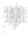
図2に示すように、電動ターボチャージャ10の電動モータ12はアルミ製のハウジング17を備える。ハウジング17の外周面には複数の放熱用のフィン18が形成されている。また、ハウジング17の内部には略円柱形状の収容空間15が形成されている。収容空間15には、ハウジング17の中心軸に沿って回転シャフト16が延びている。回転シャフト16は、軸受19a,19bを介してハウジング17に回転可能に支持されている。ここで、回転シャフト16の軸方向について図2の紙面上右側をX方向とし、図2の紙面上左側をX’方向とする。そして、回転シャフト16のX’方向の一端は、ハウジング17の外部に突出して延長している。回転シャフト16においてハウジング17の外部に突出した部分には、コンプレッサ11が一体回転可能に固定して取り付けられる。
ここで、ハウジング17は筐体を構成する。
図2に示すように、電動ターボチャージャ10の電動モータ12はアルミ製のハウジング17を備える。ハウジング17の外周面には複数の放熱用のフィン18が形成されている。また、ハウジング17の内部には略円柱形状の収容空間15が形成されている。収容空間15には、ハウジング17の中心軸に沿って回転シャフト16が延びている。回転シャフト16は、軸受19a,19bを介してハウジング17に回転可能に支持されている。ここで、回転シャフト16の軸方向について図2の紙面上右側をX方向とし、図2の紙面上左側をX’方向とする。そして、回転シャフト16のX’方向の一端は、ハウジング17の外部に突出して延長している。回転シャフト16においてハウジング17の外部に突出した部分には、コンプレッサ11が一体回転可能に固定して取り付けられる。
ここで、ハウジング17は筐体を構成する。
ハウジング17の収容空間15において、回転シャフト16にはロータ13が固定されて取り付けられている。すなわち、ロータ13はハウジング17の内部に収容されている。また、収容空間15に面するハウジング17の内周面には、帯状の突出部分である固定子受部37が形成される。ここで、固定子受部37は円筒形状の曲面である固定子取付面37aを有する。そして、固定子受部37のX方向における端部には、固定子取付面37aに隣接して、X方向側に向かって径方向外側に広がるように傾斜面37cが形成されている。すなわち、傾斜面37cは回転シャフト16の軸方向に対して傾斜している。そして、図3に示すように、固定子取付面37aと傾斜面37cとの境界は、傾斜面37cのX’方向における端部37eを構成する。また、傾斜面37cのX方向における端部は37fである。一方、固定子受部37のX’方向における端部には、固定子取付面37aに隣接して、径方向内側に突出したフランジ37dが形成されている。また、固定子受部37の固定子取付面37aには、略円筒形状のステータコア14aが焼き嵌めによって固定されている。ステータコア14aは、それぞれ均一の厚さtを有する複数の鋼板Stが、回転シャフトの軸方向に積層されて形成される(図4参照)。なお、ステータコア14aの外周面は円筒形状の曲面をなしている。また、ステータコア14aのX’方向における端部はフランジ37dに当接し、ステータコア14aはロータ13の外側においてロータ13に対向するように配置されて設けられる。さらに、ステータコア14aの両端にはステータコイル14bが取り付けられている。ステータコア14a及びステータコイル14bはステータ14を構成する。
なおここで、ロータ13は回転子を構成し、ステータ14は固定子を構成する。
また、フランジ37dはハウジング17の内部にX方向側からステータ14を組み入れる際に、ステータ14の位置を画定するストッパとして機能する。さらに、フランジ37dはステータコア14aのX’方向の端部の鋼板Stに当接しているため、ステータコア14aのX’方向の端部においては、フランジ37dによって鋼板Stの捲り上がりが防止される。
なおここで、ロータ13は回転子を構成し、ステータ14は固定子を構成する。
また、フランジ37dはハウジング17の内部にX方向側からステータ14を組み入れる際に、ステータ14の位置を画定するストッパとして機能する。さらに、フランジ37dはステータコア14aのX’方向の端部の鋼板Stに当接しているため、ステータコア14aのX’方向の端部においては、フランジ37dによって鋼板Stの捲り上がりが防止される。
図3に示すように、収容空間15に面するハウジング17の内周面において、ステータコア14aのX方向の端面が径方向外側に延長した位置に相当する線を拡張部境界線37gとする。そして、ハウジング17の内周面において、傾斜面37cの端部37eと拡張部境界線37gとの間の領域は内径拡張領域37bを構成する。
回転シャフト16の軸方向におけるステータコア14aの長さはL1とし、固定子取付面37aの長さはL2とする。また、内径拡張領域37bの長さはL3(=L1-L2)とする。ここで、図4に示すように、内径拡張領域37bの長さL3は、鋼板Stが10枚並んで積層された長さ10tよりも長い。またここで、ステータコア14aにおいて、ステータコア14aのX方向における端部から鋼板10枚が積重されて並んだ部分をステータコア14aの端部部分14cとする。すなわち、ハウジング17の内周面の内径拡張領域37bは、ステータコア14aの端部部分14cに対向する位置に形成されている。
なお、固定子取付面37aの長さL2は、電動ターボチャージャ10の全ての使用温度範囲においてハウジング17に対してステータ14の固定が可能である程度の長さとする。
なお、固定子取付面37aの長さL2は、電動ターボチャージャ10の全ての使用温度範囲においてハウジング17に対してステータ14の固定が可能である程度の長さとする。
図3に示すように、ステータコア14aの外径の大きさをΦD1とする。ΦD1は60mm前後である。なお、ステータコア14aは固定子受部37に焼き嵌めによって固定されているので、固定子受部37の固定子取付面37aの径の大きさはステータコア14aの外径の大きさとほぼ等しく、固定子取付面37aの径の大きさもΦD1とする。また、ハウジング17の内壁において固定子受部37以外の部分、すなわち傾斜面37cの端部37fからX方向に延長する部分及びフランジ37dからX’方向に延長する部分は円筒形状の曲面をなし、内径の大きさをΦD2とする。径ΦD2は、径ΦD1よりも大きい。すなわち、ハウジング17の内径の大きさは、内径拡張領域37bにおいて、X方向に向かってΦD1からΦD2に拡張しているため、内径拡張領域37bの径は固定子取付面37aの径よりも大きい。また同時に、内径拡張領域37bの径はステータコア14aの径よりも大きいため、内径拡張領域37bはステータコア14aに当接しないように形成されている。
図1を参照して、過給システム100における吸入空気の流れについて説明する。
エンジン30が所定速度以上で回転している場合、排気通路2を流入する排気の圧力によって排気ターボチャージャ40のタービン部42は回転駆動される。これにより、排気ターボチャージャ40のコンプレッサ部41が駆動され、吸気通路3を流通する吸入空気はコンプレッサ部41によって圧縮される。次に、圧縮された吸入空気は第一インタークーラ70によって冷却される。なお、この時、ECU60はエンジン30の回転数を読み込んでいる。そして、ECU60は、エンジン30が高速で回転しているか否かを判断し、エンジン30が所定速度以上の高速度で回転している場合は、電動ターボチャージャ10の電動モータ12を停止状態に維持する。回転駆動していない電動ターボチャージャ10のコンプレッサ11は、吸気通路3における吸入空気の流れに対する抵抗となる。そのため、吸入空気は第一分岐点3aを通過した後、バイパス流路5に流入する。この時、吸入空気の圧力によって逆止弁50は開状態となり、吸入空気はバイパス流路5を流通し、第二分岐点3bを介して再び吸気通路3に流入し、第二インタークーラ80を通過して、エンジン30に流入する。
エンジン30が所定速度以上で回転している場合、排気通路2を流入する排気の圧力によって排気ターボチャージャ40のタービン部42は回転駆動される。これにより、排気ターボチャージャ40のコンプレッサ部41が駆動され、吸気通路3を流通する吸入空気はコンプレッサ部41によって圧縮される。次に、圧縮された吸入空気は第一インタークーラ70によって冷却される。なお、この時、ECU60はエンジン30の回転数を読み込んでいる。そして、ECU60は、エンジン30が高速で回転しているか否かを判断し、エンジン30が所定速度以上の高速度で回転している場合は、電動ターボチャージャ10の電動モータ12を停止状態に維持する。回転駆動していない電動ターボチャージャ10のコンプレッサ11は、吸気通路3における吸入空気の流れに対する抵抗となる。そのため、吸入空気は第一分岐点3aを通過した後、バイパス流路5に流入する。この時、吸入空気の圧力によって逆止弁50は開状態となり、吸入空気はバイパス流路5を流通し、第二分岐点3bを介して再び吸気通路3に流入し、第二インタークーラ80を通過して、エンジン30に流入する。
一方、エンジン30の回転が所定速度以上の高速度回転から所定速度未満の低速度回転に切り替わった場合、排気ターボチャージャ40のタービン部42は排気ガスによる充分なエネルギーを得ることができない。そのため、排気ターボチャージャ40のコンプレッサ部41は吸入空気の過給圧を充分に高めることができない。ここで、ECU60は、エンジン30が所定速度以上で回転しているか否かを判断し、エンジン30が所定速度未満で回転している場合は、電動ターボチャージャ10の電動モータ12を回転駆動させる。また、停止状態にある車両が発進する際も、発進直後は排気ターボチャージャ40のタービン部42は排気ガスによる充分なエネルギーを得ることができないため、電動ターボチャージャ40を駆動させてもよい。
具体的には、蓄電池(図示せず)からインバータ(図示せず)を介してステータコイル14bに三相交流電流が流れ、ステータ14とロータ13との間に回転磁界が発生し、これによって回転シャフト16がコンプレッサ11とともに回転する(図2参照)。そのため、充分圧縮されずに排気ターボチャージャ40のコンプレッサ部41を通過した吸気通路3の吸入空気は、第一インタークーラ70及び第一分岐点3aを通過して、電動ターボチャージャ10のコンプレッサ11によって圧縮される。なお、この時、バイパス流路5に設けられた逆止弁50は閉状態であり、吸入空気はバイパス流路5には流通しない。そして、電動ターボチャージャ10により圧縮された吸入空気は第二分岐点3bを通過して、第二インタークーラ80によって冷却された後、エンジン30に流入する。
具体的には、蓄電池(図示せず)からインバータ(図示せず)を介してステータコイル14bに三相交流電流が流れ、ステータ14とロータ13との間に回転磁界が発生し、これによって回転シャフト16がコンプレッサ11とともに回転する(図2参照)。そのため、充分圧縮されずに排気ターボチャージャ40のコンプレッサ部41を通過した吸気通路3の吸入空気は、第一インタークーラ70及び第一分岐点3aを通過して、電動ターボチャージャ10のコンプレッサ11によって圧縮される。なお、この時、バイパス流路5に設けられた逆止弁50は閉状態であり、吸入空気はバイパス流路5には流通しない。そして、電動ターボチャージャ10により圧縮された吸入空気は第二分岐点3bを通過して、第二インタークーラ80によって冷却された後、エンジン30に流入する。
以上より、この実施の形態1に係る電動モータ12では、ハウジング17の内周面において、ステータコア14aに端部部分14cに対向する位置に設けられる内径拡張領域37bは固定子取付面37aよりも径が大きく、ステータコア14aに当接しない。そのため、焼き締め後のハウジング17の収縮による締め付け力Fをステータコア14aが受けても、ステータコア14aの端部部分14cの鋼板St自体には直接、締め付け力Fはかからない。したがって、ステータコア14aの形状を変更する必要なく、簡易な構造でステータコア14aの端部部分14cにおける鋼板Stの変形を防止することができる。
また、ステータコア14aをハウジング17の内周面に固定する方法が焼き嵌めであるため、固定用のボルト等の部品が不要であり、その分製造コストを低くすることができる。また、ハウジング17にボルト通し穴等を設ける必要がないため、電動ターボチャージャ10自体を小型化することができる。
また、ステータコア14aをハウジング17の内周面に固定する方法が焼き嵌めであるため、固定用のボルト等の部品が不要であり、その分製造コストを低くすることができる。また、ハウジング17にボルト通し穴等を設ける必要がないため、電動ターボチャージャ10自体を小型化することができる。
また、内径拡張領域37bは、回転シャフト16の軸方向に対して傾斜する傾斜面37cを有する。電動モータ12の組み立て時、ステータ14をX方向の側からハウジング17の収容空間15に組み付ける際には、傾斜面37cがステータコア14aの端部に当接することにより、ステータコア14aはよりスムーズに固定子取付面37aの内側に案内される。
また、内径拡張領域の長さL3は、鋼板Stを10枚積層した長さ10t以上であるため、より確実にステータコア14aの端部における鋼板Stの変形を防止することができる。
また、内径拡張領域の長さL3は、鋼板Stを10枚積層した長さ10t以上であるため、より確実にステータコア14aの端部における鋼板Stの変形を防止することができる。
実施の形態2.
この発明の実施の形態に係る回転電機すなわち電動モータ22を有する電動ターボチャージャ20の構成を図5に示す。この実施の形態の電動ターボチャージャ20は、実施の形態1の電動ターボチャージャ10のハウジング17を、二つの傾斜面47c,47hが形成された固定子受部47を備えるハウジング27に置き換えたものである。
なお、図1~4の参照符号と同一の符号は同一又は同様の構成要素であるので、その詳細な説明は省略する。
この発明の実施の形態に係る回転電機すなわち電動モータ22を有する電動ターボチャージャ20の構成を図5に示す。この実施の形態の電動ターボチャージャ20は、実施の形態1の電動ターボチャージャ10のハウジング17を、二つの傾斜面47c,47hが形成された固定子受部47を備えるハウジング27に置き換えたものである。
なお、図1~4の参照符号と同一の符号は同一又は同様の構成要素であるので、その詳細な説明は省略する。
図5に示すように、電動ターボチャージャ20の電動モータ22はアルミ製のハウジング27を備える。ハウジング27の外周面には複数の放熱用のフィン28が形成されている。また、ハウジング27の内部には、実施の形態1に係る電動ターボチャージャ10のハウジング17の内部と同様に略円柱形状の収容空間15が形成されている。収容空間15に面するハウジング27の内周面には、帯状の突出部分である固定子受部47が形成される。ここで、固定子受部47は円筒形状の曲面である固定子取付面47aを有する。そして、固定子受部47のX方向における端部には、固定子取付面47aに隣接して、X方向側に向かって径方向外側に広がるように傾斜面47cが形成されている。固定子取付面47aと傾斜面47cとの境界は、傾斜面47cのX’方向における端部47eを構成する。また、傾斜面47cのX方向における端部は47fである。一方、固定子受部47のX’方向における端部には、固定子取付面47aに隣接して、X’方向側に向かって径方向外側に広がるように傾斜面47hが形成されている。固定子取付面47aと傾斜面47hとの境界は、傾斜面47hのX方向における端部47kを構成する。また、傾斜面47cのX’方向における端部は47jである。また、固定子受部47の固定子取付面47aには、ステータコア14aが焼き嵌めによって固定されている。
収容空間15に面するハウジング27の内周面において、ステータコア14aのX方向の端面が径方向外側に延長した位置に相当する線を第一拡張部境界線47gとする。そして、ハウジング27の内周面において、傾斜面47cの端部47eと第一拡張部境界線47gとの間の領域は第一内径拡張領域47bを構成する。一方、ステータコア14aのX’方向の端面が径方向外側に延長した位置に相当する線は第二拡張部境界線47mとする。そして、ハウジング27の内周面において、傾斜面47hの端部47kと第二拡張部境界線47mとの間の領域は第二内径拡張領域47iを構成する。
回転シャフト16の軸方向における固定子取付面47aの長さはL4とする。また、回転シャフト16の軸方向における第一内径拡張領域47b及び第二内径拡張領域47iの長さは、それぞれL5である。また、第一内径拡張領域47b及び第二内径拡張領域47iの長さL5は、鋼板Stが10枚並んで積層された長さ10tよりも長い。またここで、ステータコア14aの端部部分14cと同様に、ステータコア14aのX’方向の端部から鋼板10枚が並んで積層された部分についても端部部分14dとする。すなわち、ハウジング17の内周面の第一内径拡張領域47b及び第二内径拡張領域47iは、それぞれステータコア14aの両端の端部部分14c,14dに対向する位置に形成されている。
なお、固定子取付面47aの長さL4は、電動ターボチャージャ20の全ての使用温度範囲においてハウジング27に対してステータ14の固定が可能である程度の長さとする。
なお、固定子取付面47aの長さL4は、電動ターボチャージャ20の全ての使用温度範囲においてハウジング27に対してステータ14の固定が可能である程度の長さとする。
固定子取付面47aの径の大きさは、実施の形態1に係る固定子取付面37aの径の大きさと同様にΦD1である。また、ハウジング27の内壁において固定子受部37以外の部分、すなわち傾斜面47cの端部47fからX方向に延長する部分及び傾斜面47hの端部47jからX’方向に延長する部分は円筒形状の曲面をなし、内径の大きさをΦD3とする。径ΦD3は径ΦD1よりも大きい。すなわち、ハウジング27の内径の大きさは、第一内径拡張領域47bにおいて、X方向に向かって拡張するとともに、第二内径拡張領域47iにおいても、X’方向に向かって拡張している。したがって、第一内径拡張領域47b及び第二内径拡張領域47iの径は、それぞれ固定子取付面47aの径よりも大きい。また同時に、第一内径拡張領域47b及び第二内径拡張領域47iの径はステータコア14aの径よりも大きいため、第一内径拡張領域47b及び第二拡張領域47iはそれぞれステータコア14aに当接しないように形成されている。
以上より、この実施の形態2に係る電動ターボチャージャ20では、ステータコア14aの両端の端部部分14c,14dに対向する位置に第一内径拡張領域47b及び第二内径拡張領域47iがそれぞれ設けられている。したがって、ステータコア14aの両端の端部部分14c,14dの鋼板Stの変形を防止することができる。
なお、実施の形態1において、内径拡張領域37bの回転シャフト16の軸方向における長さL3はステータコア14aの外径の大きさΦD1に応じて変えてもよい。すなわち、ステータコア14aの外径が大きくなる程、内径拡張領域37bの長さL3は長くなり、ステータコア14aの外径が小さくなる程、内径拡張領域37bの長さL3は短くなる。具体的には、ステータコア14aの外径の大きさΦD1が60mm前後の時は、内径拡張領域37bの長さL3は鋼板Stを10枚積層した長さ10tと同程度であるが、ΦD1がさらに大きくなれば、内径拡張領域37bの長さL3もΦD1に応じて長くなる。これにより、ハウジング17からの締め付け力Fが確保されつつ、鋼板Stの変形による捲り上がりが抑えられる。実施の形態2に係る第一内径拡張領域47b及び47iの長さL5についても同様である。
12,22 電動モータ(回転電機)、13 ロータ(回転子)、14 ステータ(固定子)、14a ステータコア、14c,14d 端部部分、16 回転シャフト、17,27 ハウジング(筐体)、37a,47a 固定子取付面、37b,47b,47i 内径拡張領域、37c,47c,47h 傾斜面、St 鋼板。
Claims (5)
- 筐体と、
前記筐体に回転可能に支持される回転シャフトと、
前記回転シャフトに固定されて取り付けられるとともに、前記筐体の内部に収容される回転子と、
前記筐体に固定されるとともに、前記回転子の径方向外側に前記回転子と対向して設けられる固定子とを備える回転電機であって、
前記固定子は、前記回転シャフトの軸方向において積層された複数の鋼板によって形成されるステータコアを有し、
前記ステータコアは前記筐体の内周面に設けられる固定子取付面に固定して取付けられ、
前記筐体の前記内周面には、前記固定子取付面に隣接し、前記ステータコアの端部部分に対向する位置に、前記ステータコアに当接しないように形成される内径拡張領域が設けられ、
前記内径拡張領域の径は前記固定子取付面の径よりも大きい回転電機。 - 前記内径拡張領域は、前記回転シャフトの前記軸方向に対して傾斜する傾斜面を有する請求項1に記載の回転電機。
- 前記回転シャフトの前記軸方向における前記内径拡張領域の長さは、前記鋼板を10枚積層した長さ以上である請求項1又は2に記載の回転電機。
- 前記内径拡張領域は、前記ステータコアの両端の前記端部部分に対向する位置にそれぞれ設けられる請求項1~3のいずれか一項に記載の回転電機。
- 前記ステータコアの前記外径が大きくなる程、前記回転シャフトの前記軸方向における前記内径拡張領域の長さは長くなる請求項1~4のいずれか一項に記載の回転電機。
Priority Applications (2)
| Application Number | Priority Date | Filing Date | Title |
|---|---|---|---|
| US15/117,931 US20160359382A1 (en) | 2014-02-13 | 2015-02-10 | Rotating electric machine |
| EP15748473.4A EP3107190A4 (en) | 2014-02-13 | 2015-02-10 | Rotating electrical machine |
Applications Claiming Priority (2)
| Application Number | Priority Date | Filing Date | Title |
|---|---|---|---|
| JP2014-025239 | 2014-02-13 | ||
| JP2014025239A JP6260323B2 (ja) | 2014-02-13 | 2014-02-13 | 回転電機 |
Publications (1)
| Publication Number | Publication Date |
|---|---|
| WO2015122405A1 true WO2015122405A1 (ja) | 2015-08-20 |
Family
ID=53800148
Family Applications (1)
| Application Number | Title | Priority Date | Filing Date |
|---|---|---|---|
| PCT/JP2015/053630 Ceased WO2015122405A1 (ja) | 2014-02-13 | 2015-02-10 | 回転電機 |
Country Status (4)
| Country | Link |
|---|---|
| US (1) | US20160359382A1 (ja) |
| EP (1) | EP3107190A4 (ja) |
| JP (1) | JP6260323B2 (ja) |
| WO (1) | WO2015122405A1 (ja) |
Cited By (2)
| Publication number | Priority date | Publication date | Assignee | Title |
|---|---|---|---|---|
| EP3168965A1 (en) * | 2015-11-16 | 2017-05-17 | Kabushiki Kaisha Toyota Jidoshokki | Electric supercharger |
| EP3347581A1 (fr) * | 2015-09-09 | 2018-07-18 | Valeo Systemes de Controle Moteur | Compresseur électrique avec vanne de contournement |
Families Citing this family (2)
| Publication number | Priority date | Publication date | Assignee | Title |
|---|---|---|---|---|
| JP6531830B2 (ja) * | 2015-10-02 | 2019-06-19 | 株式会社Ihi | 電動過給機 |
| FR3078844B1 (fr) * | 2018-03-08 | 2021-10-08 | Ifp Energies Now | Machine electrique a double flux |
Citations (2)
| Publication number | Priority date | Publication date | Assignee | Title |
|---|---|---|---|---|
| JP2011109813A (ja) * | 2009-11-18 | 2011-06-02 | Toyota Motor Corp | ステータコア |
| JP2013247815A (ja) * | 2012-05-28 | 2013-12-09 | Oita-Ken Sangyosozokiko | 電動モータ |
Family Cites Families (15)
| Publication number | Priority date | Publication date | Assignee | Title |
|---|---|---|---|---|
| JPS482090Y1 (ja) * | 1969-03-25 | 1973-01-19 | ||
| JPH0649083Y2 (ja) * | 1989-01-05 | 1994-12-12 | 富士重工業株式会社 | 発電機のステータ固定装置 |
| JP3128416B2 (ja) * | 1993-12-22 | 2001-01-29 | 株式会社日立製作所 | 回転電機 |
| JPWO2005099068A1 (ja) * | 2004-04-09 | 2008-03-06 | 株式会社ミツバ | ブラシレスモータ |
| JP4792915B2 (ja) * | 2005-10-21 | 2011-10-12 | 日本電産株式会社 | ブラシレスモータ |
| JP4747880B2 (ja) * | 2006-02-23 | 2011-08-17 | トヨタ自動車株式会社 | ステータの固定構造および電動車両 |
| JP2008011638A (ja) * | 2006-06-29 | 2008-01-17 | Mitsubishi Electric Corp | モータ及びこのモータを組み込んだ電動パワーステアリングシステム |
| ITBO20070576A1 (it) * | 2007-08-07 | 2009-02-08 | Spal Automotive Srl | Macchina elettrica. |
| JP5040988B2 (ja) * | 2009-12-22 | 2012-10-03 | トヨタ自動車株式会社 | ステータおよびこのステータを備えるモータ |
| JP2012016265A (ja) * | 2010-05-31 | 2012-01-19 | Sanyo Electric Co Ltd | モールドモータ及びこれを搭載した移動体 |
| CN103560642A (zh) * | 2010-06-11 | 2014-02-05 | 日本电产伺服有限公司 | 旋转电机 |
| JP2012097655A (ja) * | 2010-11-02 | 2012-05-24 | Nippon Densan Corp | 送風ファン |
| EP2768123B1 (en) * | 2011-10-06 | 2017-06-21 | Mitsubishi Electric Corporation | Electric motor |
| JP6004901B2 (ja) * | 2012-11-08 | 2016-10-12 | ミネベア株式会社 | レゾルバ |
| JP6127794B2 (ja) * | 2013-07-18 | 2017-05-17 | 株式会社デンソー | 回転電機の固定子 |
-
2014
- 2014-02-13 JP JP2014025239A patent/JP6260323B2/ja not_active Expired - Fee Related
-
2015
- 2015-02-10 US US15/117,931 patent/US20160359382A1/en not_active Abandoned
- 2015-02-10 WO PCT/JP2015/053630 patent/WO2015122405A1/ja not_active Ceased
- 2015-02-10 EP EP15748473.4A patent/EP3107190A4/en not_active Withdrawn
Patent Citations (2)
| Publication number | Priority date | Publication date | Assignee | Title |
|---|---|---|---|---|
| JP2011109813A (ja) * | 2009-11-18 | 2011-06-02 | Toyota Motor Corp | ステータコア |
| JP2013247815A (ja) * | 2012-05-28 | 2013-12-09 | Oita-Ken Sangyosozokiko | 電動モータ |
Non-Patent Citations (1)
| Title |
|---|
| See also references of EP3107190A4 * |
Cited By (4)
| Publication number | Priority date | Publication date | Assignee | Title |
|---|---|---|---|---|
| EP3347581A1 (fr) * | 2015-09-09 | 2018-07-18 | Valeo Systemes de Controle Moteur | Compresseur électrique avec vanne de contournement |
| EP3168965A1 (en) * | 2015-11-16 | 2017-05-17 | Kabushiki Kaisha Toyota Jidoshokki | Electric supercharger |
| JP2017089578A (ja) * | 2015-11-16 | 2017-05-25 | 株式会社豊田自動織機 | 電動過給機 |
| US10415572B2 (en) | 2015-11-16 | 2019-09-17 | Kabushiki Kaisha Toyota Jidoshokki | Electric supercharger |
Also Published As
| Publication number | Publication date |
|---|---|
| JP2015154550A (ja) | 2015-08-24 |
| US20160359382A1 (en) | 2016-12-08 |
| EP3107190A4 (en) | 2017-01-25 |
| JP6260323B2 (ja) | 2018-01-17 |
| EP3107190A1 (en) | 2016-12-21 |
Similar Documents
| Publication | Publication Date | Title |
|---|---|---|
| US10576815B2 (en) | Rotary electric machine housing and rotary electric machine equipped therewith | |
| US7560846B2 (en) | Flux barrier type synchronous reluctance motor and rotor thereof | |
| JP6260323B2 (ja) | 回転電機 | |
| WO1999021265A1 (fr) | Generateur de courant alternatif pour vehicules | |
| CN110594290B (zh) | 平箔组件、气体动压轴承和高速电机 | |
| JP2001280249A (ja) | 圧縮機および電動機 | |
| US9673668B2 (en) | Compression band shim pack for stator core, related stator and generator | |
| JP2017223151A (ja) | 電動過給圧縮機 | |
| JP4449811B2 (ja) | 電動コンプレッサ | |
| JP4100170B2 (ja) | 回転電機の冷却構造 | |
| JP2015204667A (ja) | 回転電機および回転電機の製造方法 | |
| JP2010268659A (ja) | 永久磁石式電動機回転子の冷却構造 | |
| JP2021158875A (ja) | 回転電機 | |
| JP6654414B2 (ja) | 電動圧縮機 | |
| JP6698791B1 (ja) | 回転電機 | |
| US10630152B2 (en) | Rotor for an asynchronous machine | |
| JP6453091B2 (ja) | 回転電機 | |
| JP5129518B2 (ja) | 回転電機 | |
| JP6248566B2 (ja) | 回転電機の固定子鉄心およびその製造方法 | |
| KR20200104280A (ko) | 압축기 및/또는 터빈용 전기 매체 갭 기계, 및 압축기 및/또는 터빈 | |
| JPH08251857A (ja) | 回転電機 | |
| JP7396226B2 (ja) | 回転電機 | |
| CN100385772C (zh) | 车辆用交流发电机 | |
| CN111963304A (zh) | 一种基于长齿铁芯定子电机的电辅助增压器结构 | |
| JP7609922B2 (ja) | 回転電機 |
Legal Events
| Date | Code | Title | Description |
|---|---|---|---|
| 121 | Ep: the epo has been informed by wipo that ep was designated in this application |
Ref document number: 15748473 Country of ref document: EP Kind code of ref document: A1 |
|
| REEP | Request for entry into the european phase |
Ref document number: 2015748473 Country of ref document: EP |
|
| WWE | Wipo information: entry into national phase |
Ref document number: 15117931 Country of ref document: US Ref document number: 2015748473 Country of ref document: EP |
|
| NENP | Non-entry into the national phase |
Ref country code: DE |