WO2015122456A1 - 研磨装置および研磨方法 - Google Patents
研磨装置および研磨方法 Download PDFInfo
- Publication number
- WO2015122456A1 WO2015122456A1 PCT/JP2015/053820 JP2015053820W WO2015122456A1 WO 2015122456 A1 WO2015122456 A1 WO 2015122456A1 JP 2015053820 W JP2015053820 W JP 2015053820W WO 2015122456 A1 WO2015122456 A1 WO 2015122456A1
- Authority
- WO
- WIPO (PCT)
- Prior art keywords
- polishing
- disk head
- tape
- polishing tape
- wafer
- Prior art date
- Legal status (The legal status is an assumption and is not a legal conclusion. Google has not performed a legal analysis and makes no representation as to the accuracy of the status listed.)
- Ceased
Links
Images


Classifications
-
- B—PERFORMING OPERATIONS; TRANSPORTING
- B24—GRINDING; POLISHING
- B24B—MACHINES, DEVICES, OR PROCESSES FOR GRINDING OR POLISHING; DRESSING OR CONDITIONING OF ABRADING SURFACES; FEEDING OF GRINDING, POLISHING, OR LAPPING AGENTS
- B24B21/00—Machines or devices using grinding or polishing belts; Accessories therefor
- B24B21/002—Machines or devices using grinding or polishing belts; Accessories therefor for grinding edges or bevels
-
- B—PERFORMING OPERATIONS; TRANSPORTING
- B24—GRINDING; POLISHING
- B24B—MACHINES, DEVICES, OR PROCESSES FOR GRINDING OR POLISHING; DRESSING OR CONDITIONING OF ABRADING SURFACES; FEEDING OF GRINDING, POLISHING, OR LAPPING AGENTS
- B24B9/00—Machines or devices designed for grinding edges or bevels on work or for removing burrs; Accessories therefor
- B24B9/02—Machines or devices designed for grinding edges or bevels on work or for removing burrs; Accessories therefor characterised by a special design with respect to properties of materials specific to articles to be ground
- B24B9/06—Machines or devices designed for grinding edges or bevels on work or for removing burrs; Accessories therefor characterised by a special design with respect to properties of materials specific to articles to be ground of non-metallic inorganic material, e.g. stone, ceramics, porcelain
- B24B9/065—Machines or devices designed for grinding edges or bevels on work or for removing burrs; Accessories therefor characterised by a special design with respect to properties of materials specific to articles to be ground of non-metallic inorganic material, e.g. stone, ceramics, porcelain of thin, brittle parts, e.g. semiconductors, wafers
-
- B—PERFORMING OPERATIONS; TRANSPORTING
- B24—GRINDING; POLISHING
- B24B—MACHINES, DEVICES, OR PROCESSES FOR GRINDING OR POLISHING; DRESSING OR CONDITIONING OF ABRADING SURFACES; FEEDING OF GRINDING, POLISHING, OR LAPPING AGENTS
- B24B21/00—Machines or devices using grinding or polishing belts; Accessories therefor
- B24B21/004—Machines or devices using grinding or polishing belts; Accessories therefor using abrasive rolled strips
-
- B—PERFORMING OPERATIONS; TRANSPORTING
- B24—GRINDING; POLISHING
- B24B—MACHINES, DEVICES, OR PROCESSES FOR GRINDING OR POLISHING; DRESSING OR CONDITIONING OF ABRADING SURFACES; FEEDING OF GRINDING, POLISHING, OR LAPPING AGENTS
- B24B21/00—Machines or devices using grinding or polishing belts; Accessories therefor
- B24B21/008—Machines comprising two or more tools or having several working posts
-
- B—PERFORMING OPERATIONS; TRANSPORTING
- B24—GRINDING; POLISHING
- B24B—MACHINES, DEVICES, OR PROCESSES FOR GRINDING OR POLISHING; DRESSING OR CONDITIONING OF ABRADING SURFACES; FEEDING OF GRINDING, POLISHING, OR LAPPING AGENTS
- B24B37/00—Lapping machines or devices; Accessories
- B24B37/04—Lapping machines or devices; Accessories designed for working plane surfaces
-
- H—ELECTRICITY
- H10—SEMICONDUCTOR DEVICES; ELECTRIC SOLID-STATE DEVICES NOT OTHERWISE PROVIDED FOR
- H10P—GENERIC PROCESSES OR APPARATUS FOR THE MANUFACTURE OR TREATMENT OF DEVICES COVERED BY CLASS H10
- H10P90/00—Preparation of wafers not covered by a single main group of this subclass, e.g. wafer reinforcement
- H10P90/12—Preparing bulk and homogeneous wafers
- H10P90/128—Preparing bulk and homogeneous wafers by edge treatment, e.g. chamfering
Definitions
- the present invention relates to a polishing apparatus and a polishing method for polishing a substrate such as a wafer, and more particularly to a polishing apparatus and a polishing method for polishing an edge portion of a wafer using a polishing tape.
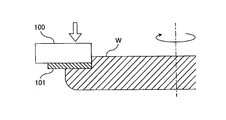
- FIG. 11 is a schematic diagram showing a polishing apparatus that polishes the edge portion of the wafer W using the polishing tape 101.
- the polishing apparatus presses the polishing tape 101 downward against the edge portion of the wafer W by the pressing member 100 while rotating the wafer W to polish the edge portion.
- the lower surface of the polishing tape 101 constitutes a polishing surface to which abrasive grains are fixed.
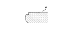
- the pressing member 100 has a flat lower surface, and the polishing tape 101 is pressed downward against the edge portion of the wafer W by the flat lower surface, so that a step portion composed of a vertical surface and a horizontal surface as shown in FIG. Formed at the edge.
- the polishing tape 101 may be displaced from a predetermined position on the pressing member 100 due to a frictional force generated between the polishing tape 101 and the wafer W.
- the vertical surface to be formed on the edge portion becomes rough.
- the edge portion of the wafer W is polished using two polishing tapes, a rough polishing tape having a rough polishing surface and a finishing polishing tape having a fine polishing surface.
- the rough polishing tape is always in contact with the vertical surface of the edge portion, so that the vertical surface of the edge portion becomes rough due to contact with the rough polishing tape. If only the finish polishing tape is used, it is possible to form a smooth vertical surface. However, if only the finish polishing tape is used, the polishing rate decreases and the throughput of the polishing apparatus decreases.
- the present invention provides a polishing apparatus and a polishing method capable of preventing a positional deviation of a polishing tape during polishing of a substrate such as a wafer and forming a smooth vertical surface on the edge portion of the substrate. With the goal.
- one aspect of the present invention includes a substrate holding portion that holds and rotates a substrate, and a polishing unit that polishes an edge portion of the substrate using a polishing tape, and the polishing unit.
- a disk head having an outer peripheral surface for supporting the polishing tape, and a head for moving the disk head in a tangential direction of the substrate and bringing the polishing tape on the outer peripheral surface of the disk head into contact with an edge portion of the substrate
- a polishing apparatus wherein the axis of the disk head is parallel to the surface of the substrate and perpendicular to the tangential direction.
- the polishing unit rotates the first reel and the second reel respectively holding the both ends of the polishing tape, and the first reel and the second reel in opposite directions. It further has a first motor and a second motor that generate torque to be generated.
- the polishing unit further includes a nip roller that presses the polishing tape against the outer peripheral surface of the disk head and curves the polishing tape along the outer peripheral surface.
- the polishing unit further includes a nip roller moving device that moves the nip roller about an axis of the disk head.
- the polishing unit further includes a head motor that rotates the disk head around its axis.
- a plurality of the polishing units are provided.
- the plurality of polishing units include a first polishing unit to which a first polishing tape is attached, and a second polishing tape having a finer polishing surface than the first polishing tape. Including a second polishing unit to which is attached.
- the first polishing tape is rotated on the outer peripheral surface of the first disk head while rotating the substrate around its axis and moving the first disk head in the tangential direction of the substrate.
- a step is formed on the edge portion by pressing against the edge portion of the substrate, and the second polishing tape is moved on the outer peripheral surface of the second disk head while moving the second disk head in the tangential direction of the substrate.
- the stationary tape is relatively large between the polishing tape in contact with the substrate and the outer peripheral surface of the disk head as compared with the case where the polishing tape is pressed against the substrate with the flat surface of the pressing member shown in FIG. Friction works. Therefore, it is possible to prevent the polishing tape from shifting from a predetermined position during the polishing of the substrate.
- the polishing tape is pressed against the edge portion of the substrate by the outer peripheral surface of the disk head while the disk head moves in the tangential direction of the substrate. For this reason, the polishing of the edge portion gradually proceeds from the outside to the inside of the edge portion. Therefore, the edge portion is polished with the first polishing tape having a rough polishing surface to form a step portion, and the step portion is further polished with the second polishing tape having a fine polishing surface, thereby achieving smoothness.
- a vertical surface can be formed at the edge portion.
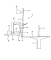
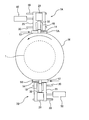
- FIG. 1 is a front view showing an embodiment of a polishing apparatus
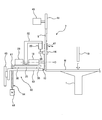
- FIG. 2 is a side view of the polishing apparatus.
- the polishing apparatus includes a substrate holding unit 1 that holds and rotates a wafer W that is an example of a substrate, and a polishing unit 7 that polishes an edge portion of the wafer W using a polishing tape 5 that is a polishing tool.
- the substrate holding unit 1 is configured to hold the lower surface of the wafer W and rotate the wafer W horizontally around its central axis.
- a polishing liquid supply nozzle 10 for supplying a polishing liquid such as pure water to the upper surface of the wafer W is disposed above the center of the wafer W held on the substrate holding unit 1. During polishing of the edge portion of the wafer W, the polishing liquid is supplied from the polishing liquid supply nozzle 10 to the center of the wafer W. The polishing liquid spreads over the entire upper surface of the wafer W by centrifugal force and protects the wafer W from polishing debris.
- the polishing unit 7 includes a disk head 12 having an outer peripheral surface that supports the polishing tape 5, a nip roller 14 that presses the polishing tape 5 against the outer peripheral surface of the disk head 12, and a head that rotates the disk head 12 around its axis O. And a motor 18.
- the axis O of the disk head 12 is parallel to the surface (upper surface) of the wafer W held by the substrate holder 1 and is perpendicular to the tangential direction of the wafer W.
- the disk head 12 is connected to the drive shaft of the head motor 18.
- the head motor 18 is configured to rotate the disk head 12 at a predetermined speed.
- the head motor 18 is fixed to the base 25.
- the nip roller 14 is rotatably held by a bearing arm 26, and the bearing arm 26 is held by an air cylinder 20 as a nip roller urging device.
- the air cylinder 20 is configured to urge the nip roller 14 toward the center of the disk head 12 via a bearing arm 26.
- a spring may be used instead of the air cylinder 20 as the nip roller urging device.
- the air cylinder 20 is held by the turning arm 32.
- the turning arm 32 is connected to a rotation shaft of a turning motor 29 as a nip roller moving device.
- the turning motor 29 is fixed to the base 25.
- the rotation axis of the turning motor 29 is aligned with the axis O of the disk head 12. Therefore, when the turning motor 29 is driven, the nip roller 14 moves around the axis O along the outer peripheral surface of the disk head 12.
- the axis of the nip roller 14 is parallel to the axis O of the disk head 12.
- the base 25 is supported by a horizontal linear guide 30 extending in a direction parallel to the tangential direction of the wafer W, and the movement of the base 25 is limited to a direction parallel to the tangential direction of the wafer W by the horizontal linear guide 30.
- the polishing unit 7 rotates the first tension reel 41 and the second tension reel 42 holding the both ends of the polishing tape 5 respectively, and the first tension reel 41 and the second tension reel 42 in opposite directions. It further has a first tension motor 43 and a second tension motor 44 that generate torque. The first tension reel 41 and the second tension reel 42 are disposed above the disk head 12.
- the polishing tape 5 extends from the first tension reel 41 to the second tension reel 42 via the disk head 12. Since the first tension reel 41 and the second tension reel 42 are applied with torque that rotates the tension reels 41 and 42 in opposite directions, a tension is applied to the polishing tape 5. Between the first and second tension reels 41 and 42 and the disk head 12, a first guide roller 47 and a second guide roller 48 are arranged, and the first and second tension reels 41, A polishing tape 5 extending between 42 and the disk head 12 is supported.
- the polishing tape 5 is curved along the outer peripheral surface of the disk head 12, and the curved portion is brought into contact with the wafer W. Compared to the case where the polishing tape 101 is pressed against the wafer W on the flat surface of the pressing member 100 shown in FIG. 11, a relatively large rest is provided between the polishing tape 5 in contact with the wafer W and the outer peripheral surface of the disk head 12. Friction works. Therefore, it is possible to prevent the polishing tape 5 from being displaced from a predetermined position during the polishing of the wafer W. In order to hold the polishing tape 5 on the disk head 12, a vacuum suction hole for vacuum suction of the polishing tape 5 may be formed on the outer peripheral surface of the disk head 12.
- One surface of the polishing tape 5 constitutes a polishing surface for holding abrasive grains, and the other surface (that is, the back surface) is supported by the outer peripheral surface of the disk head 12.
- the outer peripheral surface of the disk head 12 may have a width wider than the width of the polishing tape 5.
- the position of the inner edge (wafer side edge or substrate side edge) of the polishing tape 5 preferably matches the position of the edge of the disk head 12.
- the nip roller 14 curves the polishing tape 5 along the outer peripheral surface of the disk head 12 by pressing the back surface of the polishing tape 5 against the outer peripheral surface of the disk head 12, thereby increasing the contact area between the polishing tape 5 and the disk head 12. Let The polishing tape 5 is sandwiched between the nip roller 14 and the disk head 12.
- the polishing tape 5 is curved along the outer peripheral surface of the disk head 12 and is further wound around the outer peripheral surface of the disk head 12 by the nip roller 14.
- a large static friction acts between the back surface of the polishing tape 5 and the outer peripheral surface of the disk head 12, whereby the displacement of the polishing tape 5 can be reliably prevented.
- the length of the polishing tape 5 that contacts the outer peripheral surface of the disk head 12, that is, the contact area between the polishing tape 5 and the disk head 12 varies according to the position of the nip roller 14.
- the turning motor 29 functioning as a nip roller moving device can change the length of the polishing tape 5 in contact with the outer peripheral surface of the disk head 12 by moving the nip roller 14 about the axis O of the disk head 12. it can.
- the length of the polishing tape 5 in contact with the outer peripheral surface of the disk head 12 is at least half of the entire circumference of the disk head 12.
- the nip roller 14 is preferably arranged at a position where the polishing tape 5 extends over at least a half circumference of the disk head 12. In the example shown in FIG. 1, the nip roller 14 is disposed at a position where the polishing tape 5 extends over the 3/4 circumference of the disk head 12.
- the first guide roller 47 is configured to be movable in parallel with the axis O of the disk head 12.
- the relative position of the polishing tape 5 with respect to the disk head 12 in the axial direction of the disk head 12 (that is, the direction in which the axis O extends) is adjusted by the first guide roller 47.
- the polishing tape 5 is pulled out from the first tension reel 41, proceeds in the circumferential direction of the disk head 12 in synchronization with the rotation of the disk head 12, and the second The tension reel 42 is wound up.
- the polishing tape 5 advances from the first tension reel 41 to the second tension reel 42 through the first guide roller 47, the disk head 12, the nip roller 14, and the second guide roller 48 in this order.
- the polishing unit 7 further includes an air cylinder 50 as a head moving device for moving the disk head 12 and the nip roller 14 in the tangential direction of the wafer W.
- the piston rod 51 of the air cylinder 50 is connected to the base 25 (see FIG. 2).
- the disk head 12 and the nip roller 14 are movable together with the base 25. Therefore, the air cylinder 50 moves the disk head 12 and the nip roller 14 in the tangential direction of the wafer W while the polishing tape 5 is supported on the outer peripheral surface of the disk head 12.
- a ball screw and a servo are used instead of the air cylinder 50.
- a combination with a motor may be used.
- the air cylinder 50 moves the disk head 12 in the tangential direction of the wafer W to bring the polishing tape 5 on the outer peripheral surface of the disk head 12 into contact with the edge portion of the wafer W.
- the polishing tape 5 is pressed against the edge portion of the wafer W by the lower end portion of the disk head 12.
- the moving direction and the rotating direction of the disk head 12 are directions in which the polishing tape 5 moves in the direction opposite to the moving direction of the edge portion of the wafer W. This is to increase the polishing rate of the wafer W.
- Polishing of the edge portion of the wafer W is performed as follows.
- the wafer W is held horizontally by the substrate holder 1 and rotated about the axis of the wafer W.
- a polishing liquid (for example, pure water) is supplied from the polishing liquid supply nozzle 10 to the center of the wafer W.
- the head motor 18 rotates the disk head 12 at a predetermined speed
- the air cylinder 50 moves the disk head 12 and the nip roller 14 together with the polishing tape 5 in the tangential direction of the wafer W, and moves the disk head 12 on the outer peripheral surface of the disk head 12.
- the polishing tape 5 is brought into contact with the edge portion of the wafer W.
- the lowermost end portion of the disk head 12 presses the polishing tape 5 against the edge portion of the wafer W.
- the edge portion of the wafer W is polished by the polishing tape 5, and a step portion as shown in FIG. 12 is formed at the edge portion.
- the polishing tape 5 is bent along the outer peripheral surface of the disk head 12 and wound around the outer peripheral surface of the disk head 12 by the nip roller 14. Accordingly, a relatively large static friction acts between the back surface of the polishing tape 5 and the outer peripheral surface of the disk head 12, thereby preventing displacement of the polishing tape 5. Therefore, the polishing tape 5 can form a smooth vertical surface (see FIG. 12) at the edge portion of the wafer W.
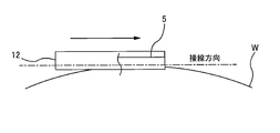
- FIG. 3 is a plan view showing the relative positions of the disk head 12 and the edge portion of the wafer W when the polishing tape 5 contacts the edge portion of the wafer W.
- FIG. 4 shows the disk head 12 shown in FIG. It is sectional drawing of the edge part grind
- FIG. 5 is a plan view showing the relative positions of the disk head 12 and the edge portion of the wafer W when the disk head 12 is further moved in the tangential direction of the wafer W.
- FIG. It is sectional drawing of the edge part grind
- the polishing tape 5 polishes the inner portion of the edge portion of the wafer W and forms a larger step portion at the edge portion.
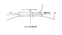
- FIG. 7 is a plan view showing the relative positions of the disk head 12 and the edge portion of the wafer W when the axis O of the disk head 12 coincides with the radial direction of the wafer W when viewed from above the wafer W.
- FIG. 8 is a sectional view of the edge portion polished by the polishing tape 5 when the disk head 12 is in the position shown in FIG. The polishing tape 5 polishes the innermost portion of the edge portion of the wafer W, and forms a larger step portion at the edge portion as shown in FIG.
- the polishing of the edge portion gradually proceeds from the outside to the inside of the edge portion. Therefore, rough polishing and finish polishing of the edge portion can be performed using two types of polishing tapes. That is, the edge portion is polished with a first polishing tape having a rough polishing surface to form a stepped portion, and the stepped portion is further polished with a second polishing tape having a finer polishing surface, thereby achieving smoothness.
- a vertical surface can be formed at the edge portion.
- FIG. 9 is a schematic diagram showing a polishing apparatus having two polishing units 7A and 7B.
- the first polishing unit 7A and the second polishing unit 7B shown in FIG. 9 have the same configuration as the polishing unit 7 shown in FIGS. 1 and 2, but for simplification of description, FIG. However, some of the components of the first polishing unit 7A and the second polishing unit 7B are not shown.
- the first polishing unit 7A and the second polishing unit 7B are arranged along the edge portion of the wafer W held by the substrate holding unit 1.
- the first polishing unit 7 ⁇ / b> A and the second polishing unit 7 ⁇ / b> B are arranged symmetrically around the wafer W held by the substrate holding unit 1.
- a first polishing tape 5A having a rough polishing surface is attached to the first polishing unit 7A
- a second polishing tape 5B having a fine polishing surface is attached to the second polishing unit 7B. It has been.
- Polishing of the edge portion of the wafer W is performed as follows.
- the wafer W is held horizontally by the substrate holder 1 and rotated about the axis of the wafer W.
- a polishing liquid is supplied to the central portion of the wafer W from a polishing liquid supply nozzle 10 (see FIG. 2).
- the disk head 12 of the first polishing unit 7 ⁇ / b> A moves in the tangential direction of the wafer W to bring the first polishing tape 5 ⁇ / b> A into contact with the edge portion of the wafer W.
- the first polishing tape 5A is pressed against the edge portion of the wafer W by the outer peripheral surface of the disk head 12 of the first polishing unit 7A to form a step portion at the edge portion.
- the disk head 12 of the second polishing unit 7B moves in the tangential direction of the wafer W, and the second polishing tape 5B is moved to the wafer. Contact the edge of W.
- the second polishing tape 5B is pressed against the step portion by the outer peripheral surface of the disk head 12 of the second polishing unit 7B, and further polishes the step portion.
- the first polishing tape 5A is a rough polishing tape having a rough polishing surface
- the second polishing tape 5B is a final polishing tape having a fine polishing surface.
- the first polishing tape 5A polishes the edge portion of the wafer W at a high polishing rate (also referred to as a removal rate), and the second polishing tape 5B is formed by the first polishing tape 5A. Finish polishing the stepped part. Therefore, the vertical surface of the stepped portion can be made smooth while improving the polishing rate of the wafer W.
- polishing units 7 may be provided.
- three or more polishing tapes having polishing surfaces with different surface roughness may be used.
- FIG. 10 is a side view showing another embodiment of the polishing apparatus.
- the polishing unit 7 of this embodiment includes a lifting mechanism 60 that raises and lowers the disk head 12, the nip roller 14, the head motor 18, and the turning motor 29.
- the lifting mechanism 60 includes a lifting table 62 that supports the horizontal linear guide 30 and a lifting actuator 64 that raises and lowers the lifting table 62.
- the elevating table 62 is connected to a vertical linear guide 65.
- the vertical linear guide 65 is configured to limit the movement of the lifting table 62 in the vertical direction.
- the lifting / lowering actuator 64 includes a ball screw 67 rotatably connected to the lifting / lowering table 62 and a servo motor 68 that rotates the ball screw 67.
- the servo motor 68 rotates the ball screw 67
- the lifting table 62 is raised or lowered. Since the disk head 12, the nip roller 14, the head motor 18, and the turning motor 29 are connected to the lifting table 62 via the horizontal linear guide 30 and the base 25, the lifting actuator 64 is connected to the disk head 12, the nip roller. 14, the head motor 18 and the turning motor 29 can be moved up and down integrally.
- the polishing unit 7 configured as described above can precisely control the polishing amount of the wafer W (that is, the depth of the step portion formed in the edge portion).
- the present invention is applicable to a polishing apparatus and a polishing method for polishing an edge portion of a wafer using a polishing tape.
Landscapes
- Engineering & Computer Science (AREA)
- Mechanical Engineering (AREA)
- Chemical & Material Sciences (AREA)
- Ceramic Engineering (AREA)
- Inorganic Chemistry (AREA)
- Finish Polishing, Edge Sharpening, And Grinding By Specific Grinding Devices (AREA)
- Mechanical Treatment Of Semiconductor (AREA)
- Grinding And Polishing Of Tertiary Curved Surfaces And Surfaces With Complex Shapes (AREA)
Abstract
Description
本発明の好ましい態様は、前記研磨ユニットは、前記研磨テープを前記円盤ヘッドの外周面に押し付けて前記研磨テープを前記外周面に沿って湾曲させるニップローラーをさらに備えたことを特徴とする。
本発明の好ましい態様は、前記研磨ユニットは、前記ニップローラーを前記円盤ヘッドの軸心まわりに移動させるニップローラー移動装置をさらに備えたことを特徴とする。
本発明の好ましい態様は、前記研磨ユニットは、前記円盤ヘッドをその軸心まわりに回転させるヘッドモータをさらに有することを特徴とする。
本発明の好ましい態様は、前記複数の研磨ユニットは、第1の研磨テープが取り付けられた第1の研磨ユニットと、前記第1の研磨テープよりもきめの細かい研磨面を有する第2の研磨テープが取り付けられた第2の研磨ユニットを含むことを特徴とする。
図1は、研磨装置の一実施形態を示す正面図であり、図2は、研磨装置の側面図である。研磨装置は、基板の一例であるウェハWを保持して回転させる基板保持部1と、研磨具である研磨テープ5を用いてウェハWのエッジ部を研磨する研磨ユニット7とを備えている。基板保持部1は、ウェハWの下面を保持し、ウェハWをその中心軸まわりに水平に回転させるように構成されている。
5,5A,5B 研磨テープ
7,7A,7B 研磨ユニット
10 研磨液供給ノズル
12 円盤ヘッド
14 ニップローラー
18 ヘッドモータ
20 エアシリンダ(ニップローラー付勢装置)
25 基台
26 軸受アーム
29 旋回モータ
30 水平リニアガイド
32 旋回アーム
41 第1のテンションリール
42 第2のテンションリール
43 第1のテンションモータ
44 第2のテンションモータ
47 第1のガイドローラー
48 第2のガイドローラー
50 エアシリンダ(ヘッド移動装置)
51 ピストンロッド
60 昇降機構
62 昇降テーブル
64 昇降アクチュエータ
65 鉛直リニアガイド
67 ボールねじ
68 サーボモータ
Claims (8)
- 基板を保持して回転させる基板保持部と、
前記基板のエッジ部を研磨テープを用いて研磨する研磨ユニットとを備え、
前記研磨ユニットは、
前記研磨テープを支持する外周面を有する円盤ヘッドと、
前記円盤ヘッドを前記基板の接線方向に移動させ、前記円盤ヘッドの外周面上の前記研磨テープを前記基板のエッジ部に接触させるヘッド移動装置とを有し、
前記円盤ヘッドの軸心は、前記基板の表面と平行であり、かつ前記接線方向に対して垂直であることを特徴とする研磨装置。 - 前記研磨ユニットは、
前記研磨テープの両端部をそれぞれ保持した第1のリールおよび第2のリールと、
前記第1のリールおよび前記第2のリールを互いに反対方向に回転させるトルクを発生する第1のモータおよび第2のモータをさらに有することを特徴とする請求項1に記載の研磨装置。 - 前記研磨ユニットは、前記研磨テープを前記円盤ヘッドの外周面に押し付けて前記研磨テープを前記外周面に沿って湾曲させるニップローラーをさらに備えたことを特徴とする請求項1に記載の研磨装置。
- 前記研磨ユニットは、前記ニップローラーを前記円盤ヘッドの軸心まわりに移動させるニップローラー移動装置をさらに備えたことを特徴とする請求項3に記載の研磨装置。
- 前記研磨ユニットは、前記円盤ヘッドをその軸心まわりに回転させるヘッドモータをさらに有することを特徴とする請求項1に記載の研磨装置。
- 前記研磨ユニットは、複数設けられていることを特徴とする請求項1に記載の研磨装置。
- 前記複数の研磨ユニットは、第1の研磨テープが取り付けられた第1の研磨ユニットと、前記第1の研磨テープよりもきめの細かい研磨面を有する第2の研磨テープが取り付けられた第2の研磨ユニットを含むことを特徴とする請求項6に記載の研磨装置。
- 基板をその軸心まわりに回転させ、
第1の円盤ヘッドを前記基板の接線方向に移動させながら、前記第1の円盤ヘッドの外周面で第1の研磨テープを前記基板のエッジ部に押し付けて前記エッジ部に段部を形成し、
第2の円盤ヘッドを前記基板の接線方向に移動させながら、前記第2の円盤ヘッドの外周面で第2の研磨テープを前記段部に押し付けて前記段部を研磨する工程を含み、
前記第2の研磨テープは、前記第1の研磨テープの研磨面よりもきめの細かい研磨面を有していることを特徴とする研磨方法。
Priority Applications (5)
| Application Number | Priority Date | Filing Date | Title |
|---|---|---|---|
| EP15748812.3A EP3108998B1 (en) | 2014-02-17 | 2015-02-12 | Polishing apparatus and polishing method |
| CN201580008700.8A CN106029297B (zh) | 2014-02-17 | 2015-02-12 | 研磨装置及研磨方法 |
| KR1020167024837A KR102237719B1 (ko) | 2014-02-17 | 2015-02-12 | 연마 장치 및 연마 방법 |
| US15/118,184 US10144103B2 (en) | 2014-02-17 | 2015-02-12 | Polishing apparatus and polishing method |
| US16/166,767 US10414013B2 (en) | 2014-02-17 | 2018-10-22 | Polishing method and polishing apparatus |
Applications Claiming Priority (2)
| Application Number | Priority Date | Filing Date | Title |
|---|---|---|---|
| JP2014027780A JP6204848B2 (ja) | 2014-02-17 | 2014-02-17 | 研磨装置および研磨方法 |
| JP2014-027780 | 2014-02-17 |
Related Child Applications (2)
| Application Number | Title | Priority Date | Filing Date |
|---|---|---|---|
| US15/118,184 A-371-Of-International US10144103B2 (en) | 2014-02-17 | 2015-02-12 | Polishing apparatus and polishing method |
| US16/166,767 Continuation US10414013B2 (en) | 2014-02-17 | 2018-10-22 | Polishing method and polishing apparatus |
Publications (1)
| Publication Number | Publication Date |
|---|---|
| WO2015122456A1 true WO2015122456A1 (ja) | 2015-08-20 |
Family
ID=53800197
Family Applications (1)
| Application Number | Title | Priority Date | Filing Date |
|---|---|---|---|
| PCT/JP2015/053820 Ceased WO2015122456A1 (ja) | 2014-02-17 | 2015-02-12 | 研磨装置および研磨方法 |
Country Status (7)
| Country | Link |
|---|---|
| US (2) | US10144103B2 (ja) |
| EP (1) | EP3108998B1 (ja) |
| JP (2) | JP6204848B2 (ja) |
| KR (1) | KR102237719B1 (ja) |
| CN (1) | CN106029297B (ja) |
| TW (2) | TWI621167B (ja) |
| WO (1) | WO2015122456A1 (ja) |
Families Citing this family (7)
| Publication number | Priority date | Publication date | Assignee | Title |
|---|---|---|---|---|
| JP6672104B2 (ja) * | 2016-08-02 | 2020-03-25 | 株式会社荏原製作所 | 研磨装置および研磨方法 |
| JP6920849B2 (ja) * | 2017-03-27 | 2021-08-18 | 株式会社荏原製作所 | 基板処理方法および装置 |
| WO2019043796A1 (ja) * | 2017-08-29 | 2019-03-07 | 株式会社 荏原製作所 | 研磨装置および研磨方法 |
| TWI725225B (zh) * | 2017-08-30 | 2021-04-21 | 日商荏原製作所股份有限公司 | 研磨裝置及研磨方法 |
| JP7121572B2 (ja) * | 2018-07-20 | 2022-08-18 | 株式会社荏原製作所 | 研磨装置および研磨方法 |
| JP2021091033A (ja) * | 2019-12-10 | 2021-06-17 | キオクシア株式会社 | 研磨装置、研磨ヘッド、研磨方法、及び半導体装置の製造方法 |
| JP2023141507A (ja) * | 2022-03-24 | 2023-10-05 | 株式会社荏原製作所 | 研磨方法および研磨装置 |
Citations (9)
| Publication number | Priority date | Publication date | Assignee | Title |
|---|---|---|---|---|
| JPH01115562A (ja) * | 1987-10-23 | 1989-05-08 | Kyosan Electric Mfg Co Ltd | 超仕上装置 |
| JPH0985599A (ja) * | 1995-09-21 | 1997-03-31 | Nippon Micro Coating Kk | 研磨テープによる研磨装置 |
| JPH10217077A (ja) * | 1997-01-30 | 1998-08-18 | Kuramoto Seisakusho:Kk | ディスク基板の加工方法と加工装置 |
| JP2002126981A (ja) * | 2000-10-25 | 2002-05-08 | Sanshin:Kk | 円板状部材周縁部研磨装置 |
| JP2003175449A (ja) * | 2001-12-10 | 2003-06-24 | Sumitomo Metal Ind Ltd | 鋼帯の研削装置 |
| US7115023B1 (en) * | 2005-06-29 | 2006-10-03 | Lam Research Corporation | Process tape for cleaning or processing the edge of a semiconductor wafer |
| JP2011161625A (ja) * | 2010-01-15 | 2011-08-25 | Ebara Corp | 研磨装置、研磨方法、研磨具を押圧する押圧部材 |
| JP2012231191A (ja) * | 2007-12-03 | 2012-11-22 | Ebara Corp | 研磨装置および研磨方法 |
| JP2013188839A (ja) * | 2012-03-14 | 2013-09-26 | Nisshin Steel Co Ltd | 鋼帯研磨機の異常検出装置及び異常検出方法 |
Family Cites Families (19)
| Publication number | Priority date | Publication date | Assignee | Title |
|---|---|---|---|---|
| US4930259A (en) * | 1988-02-19 | 1990-06-05 | Magnetic Perpherals Inc. | Magnetic disk substrate polishing assembly |
| US5099615A (en) * | 1989-09-22 | 1992-03-31 | Exclusive Design Company, Inc. | Automated rigid-disk finishing system providing in-line process control |
| US5088240A (en) * | 1989-09-22 | 1992-02-18 | Exclusive Design Company, Inc. | Automated rigid-disk finishing system providing in-line process control |
| US5443415A (en) | 1993-09-24 | 1995-08-22 | International Technology Partners, Inc. | Burnishing apparatus for flexible magnetic disks and method therefor |
| US5433415A (en) * | 1994-09-01 | 1995-07-18 | Corsam Industries Inc. | Adjustable book holder |
| US5643044A (en) * | 1994-11-01 | 1997-07-01 | Lund; Douglas E. | Automatic chemical and mechanical polishing system for semiconductor wafers |
| JPH11198015A (ja) | 1998-01-06 | 1999-07-27 | Hirata Corp | ハードディスクのテキスチャ加工装置 |
| JP3510584B2 (ja) * | 2000-11-07 | 2004-03-29 | スピードファム株式会社 | 円板形ワークの外周研磨装置 |
| JP4125148B2 (ja) * | 2003-02-03 | 2008-07-30 | 株式会社荏原製作所 | 基板処理装置 |
| JP2005305586A (ja) * | 2004-04-20 | 2005-11-04 | Nihon Micro Coating Co Ltd | 研磨装置 |
| US20080293344A1 (en) * | 2007-05-21 | 2008-11-27 | Applied Materials, Inc. | Methods and apparatus for polishing a notch of a substrate using a polishing pad |
| JP2008293344A (ja) | 2007-05-25 | 2008-12-04 | Hitachi Ltd | 保険契約管理方法、その管理プログラム、及びその装置 |
| JP2008132592A (ja) * | 2007-12-07 | 2008-06-12 | Ebara Corp | ポリッシング装置およびポリッシング方法 |
| KR20090063804A (ko) * | 2007-12-14 | 2009-06-18 | 주식회사 실트론 | 연삭 휠 트루잉 공구 및 그 제작방법, 이를 이용한 트루잉장치, 연삭 휠의 제작방법, 및 웨이퍼 에지 연삭장치 |
| JP5464497B2 (ja) * | 2010-08-19 | 2014-04-09 | 株式会社サンシン | 基板研磨方法及びその装置 |
| JP5886602B2 (ja) * | 2011-03-25 | 2016-03-16 | 株式会社荏原製作所 | 研磨装置および研磨方法 |
| US9457447B2 (en) * | 2011-03-28 | 2016-10-04 | Ebara Corporation | Polishing apparatus and polishing method |
| JP2014027000A (ja) * | 2012-07-24 | 2014-02-06 | Disco Abrasive Syst Ltd | 研削装置 |
| JP6100541B2 (ja) * | 2013-01-30 | 2017-03-22 | 株式会社荏原製作所 | 研磨方法 |
-
2014
- 2014-02-17 JP JP2014027780A patent/JP6204848B2/ja active Active
-
2015
- 2015-02-11 TW TW104104534A patent/TWI621167B/zh active
- 2015-02-11 TW TW107107035A patent/TWI667100B/zh active
- 2015-02-12 US US15/118,184 patent/US10144103B2/en active Active
- 2015-02-12 EP EP15748812.3A patent/EP3108998B1/en active Active
- 2015-02-12 KR KR1020167024837A patent/KR102237719B1/ko active Active
- 2015-02-12 CN CN201580008700.8A patent/CN106029297B/zh active Active
- 2015-02-12 WO PCT/JP2015/053820 patent/WO2015122456A1/ja not_active Ceased
-
2017
- 2017-09-01 JP JP2017168396A patent/JP6483772B2/ja active Active
-
2018
- 2018-10-22 US US16/166,767 patent/US10414013B2/en active Active
Patent Citations (9)
| Publication number | Priority date | Publication date | Assignee | Title |
|---|---|---|---|---|
| JPH01115562A (ja) * | 1987-10-23 | 1989-05-08 | Kyosan Electric Mfg Co Ltd | 超仕上装置 |
| JPH0985599A (ja) * | 1995-09-21 | 1997-03-31 | Nippon Micro Coating Kk | 研磨テープによる研磨装置 |
| JPH10217077A (ja) * | 1997-01-30 | 1998-08-18 | Kuramoto Seisakusho:Kk | ディスク基板の加工方法と加工装置 |
| JP2002126981A (ja) * | 2000-10-25 | 2002-05-08 | Sanshin:Kk | 円板状部材周縁部研磨装置 |
| JP2003175449A (ja) * | 2001-12-10 | 2003-06-24 | Sumitomo Metal Ind Ltd | 鋼帯の研削装置 |
| US7115023B1 (en) * | 2005-06-29 | 2006-10-03 | Lam Research Corporation | Process tape for cleaning or processing the edge of a semiconductor wafer |
| JP2012231191A (ja) * | 2007-12-03 | 2012-11-22 | Ebara Corp | 研磨装置および研磨方法 |
| JP2011161625A (ja) * | 2010-01-15 | 2011-08-25 | Ebara Corp | 研磨装置、研磨方法、研磨具を押圧する押圧部材 |
| JP2013188839A (ja) * | 2012-03-14 | 2013-09-26 | Nisshin Steel Co Ltd | 鋼帯研磨機の異常検出装置及び異常検出方法 |
Also Published As
| Publication number | Publication date |
|---|---|
| EP3108998A1 (en) | 2016-12-28 |
| KR20160124142A (ko) | 2016-10-26 |
| TWI667100B (zh) | 2019-08-01 |
| US10414013B2 (en) | 2019-09-17 |
| US20190054589A1 (en) | 2019-02-21 |
| CN106029297A (zh) | 2016-10-12 |
| JP6204848B2 (ja) | 2017-09-27 |
| KR102237719B1 (ko) | 2021-04-09 |
| JP6483772B2 (ja) | 2019-03-13 |
| CN106029297B (zh) | 2019-07-16 |
| US10144103B2 (en) | 2018-12-04 |
| JP2015150662A (ja) | 2015-08-24 |
| TWI621167B (zh) | 2018-04-11 |
| US20170165804A1 (en) | 2017-06-15 |
| TW201535503A (zh) | 2015-09-16 |
| EP3108998B1 (en) | 2019-08-14 |
| EP3108998A4 (en) | 2017-11-01 |
| JP2017209784A (ja) | 2017-11-30 |
| TW201831274A (zh) | 2018-09-01 |
Similar Documents
| Publication | Publication Date | Title |
|---|---|---|
| JP6483772B2 (ja) | 研磨装置 | |
| JP6178478B2 (ja) | 研磨方法 | |
| KR102104430B1 (ko) | 연마 방법 | |
| JP2011224680A (ja) | 研磨方法及び研磨装置 | |
| WO2021044735A1 (ja) | 研磨装置 | |
| JP6672104B2 (ja) | 研磨装置および研磨方法 | |
| TW202333892A (zh) | 於工件研磨後使得研磨頭上升的方法、工件的研磨裝置、及記錄了程式的電腦可讀取記錄媒體 | |
| US6638147B2 (en) | Polishing method for removing corner material from a semi-conductor wafer | |
| JP6412217B2 (ja) | 研磨装置 | |
| JP6786292B2 (ja) | 研磨装置 | |
| JP4289764B2 (ja) | テープ研磨装置 | |
| JP2016159384A (ja) | 研磨装置及び研磨方法 | |
| JP5484172B2 (ja) | 研磨パッドのテーパ面形成方法 | |
| WO2019043796A1 (ja) | 研磨装置および研磨方法 | |
| JP2009255184A (ja) | ウェーハ研磨装置 | |
| JP6171053B2 (ja) | 研磨装置 | |
| JP2020104189A (ja) | 研磨方法および研磨装置 | |
| JP2013230556A (ja) | 研磨装置 | |
| KR20100045819A (ko) | 테이프 연마장치 |
Legal Events
| Date | Code | Title | Description |
|---|---|---|---|
| 121 | Ep: the epo has been informed by wipo that ep was designated in this application |
Ref document number: 15748812 Country of ref document: EP Kind code of ref document: A1 |
|
| WWE | Wipo information: entry into national phase |
Ref document number: 15118184 Country of ref document: US |
|
| NENP | Non-entry into the national phase |
Ref country code: DE |
|
| REEP | Request for entry into the european phase |
Ref document number: 2015748812 Country of ref document: EP |
|
| WWE | Wipo information: entry into national phase |
Ref document number: 2015748812 Country of ref document: EP |
|
| ENP | Entry into the national phase |
Ref document number: 20167024837 Country of ref document: KR Kind code of ref document: A |