WO2015125474A1 - 車両用空調装置 - Google Patents
車両用空調装置 Download PDFInfo
- Publication number
- WO2015125474A1 WO2015125474A1 PCT/JP2015/000755 JP2015000755W WO2015125474A1 WO 2015125474 A1 WO2015125474 A1 WO 2015125474A1 JP 2015000755 W JP2015000755 W JP 2015000755W WO 2015125474 A1 WO2015125474 A1 WO 2015125474A1
- Authority
- WO
- WIPO (PCT)
- Prior art keywords
- air
- flow path
- vehicle
- intake duct
- heat
- Prior art date
- Legal status (The legal status is an assumption and is not a legal conclusion. Google has not performed a legal analysis and makes no representation as to the accuracy of the status listed.)
- Ceased
Links
Images



Classifications
-
- B—PERFORMING OPERATIONS; TRANSPORTING
- B60—VEHICLES IN GENERAL
- B60H—ARRANGEMENTS OF HEATING, COOLING, VENTILATING OR OTHER AIR-TREATING DEVICES SPECIALLY ADAPTED FOR PASSENGER OR GOODS SPACES OF VEHICLES
- B60H1/00—Heating, cooling or ventilating devices
- B60H1/02—Heating, cooling or ventilating devices the heat being derived from the propulsion plant
- B60H1/14—Heating, cooling or ventilating devices the heat being derived from the propulsion plant other than from cooling liquid of the plant
-
- B—PERFORMING OPERATIONS; TRANSPORTING
- B60—VEHICLES IN GENERAL
- B60H—ARRANGEMENTS OF HEATING, COOLING, VENTILATING OR OTHER AIR-TREATING DEVICES SPECIALLY ADAPTED FOR PASSENGER OR GOODS SPACES OF VEHICLES
- B60H1/00—Heating, cooling or ventilating devices
- B60H1/02—Heating, cooling or ventilating devices the heat being derived from the propulsion plant
- B60H1/14—Heating, cooling or ventilating devices the heat being derived from the propulsion plant other than from cooling liquid of the plant
- B60H1/16—Heating, cooling or ventilating devices the heat being derived from the propulsion plant other than from cooling liquid of the plant the air being heated by direct contact with the plant, e.g. air-cooled motor
-
- B—PERFORMING OPERATIONS; TRANSPORTING
- B60—VEHICLES IN GENERAL
- B60H—ARRANGEMENTS OF HEATING, COOLING, VENTILATING OR OTHER AIR-TREATING DEVICES SPECIALLY ADAPTED FOR PASSENGER OR GOODS SPACES OF VEHICLES
- B60H1/00—Heating, cooling or ventilating devices
- B60H1/00321—Heat exchangers for air-conditioning devices
-
- F—MECHANICAL ENGINEERING; LIGHTING; HEATING; WEAPONS; BLASTING
- F01—MACHINES OR ENGINES IN GENERAL; ENGINE PLANTS IN GENERAL; STEAM ENGINES
- F01P—COOLING OF MACHINES OR ENGINES IN GENERAL; COOLING OF INTERNAL-COMBUSTION ENGINES
- F01P5/00—Pumping cooling-air or liquid coolants
- F01P5/02—Pumping cooling-air; Arrangements of cooling-air pumps, e.g. fans or blowers
- F01P5/06—Guiding or ducting air to, or from, ducted fans
-
- B—PERFORMING OPERATIONS; TRANSPORTING
- B60—VEHICLES IN GENERAL
- B60H—ARRANGEMENTS OF HEATING, COOLING, VENTILATING OR OTHER AIR-TREATING DEVICES SPECIALLY ADAPTED FOR PASSENGER OR GOODS SPACES OF VEHICLES
- B60H1/00—Heating, cooling or ventilating devices
- B60H1/00007—Combined heating, ventilating, or cooling devices
- B60H1/00207—Combined heating, ventilating, or cooling devices characterised by the position of the HVAC devices with respect to the passenger compartment
- B60H2001/00214—Devices in front of the passenger compartment
Definitions
- the present invention relates to a vehicle air conditioner that uses the heat of an engine room.
- the present invention provides a vehicle air conditioner that utilizes the heat of an engine room by utilizing an existing space without newly securing a dedicated space for installing a heat exchanger.
- the vehicle air conditioner of the present invention has a heat exchanger, a first air flow path, and a second air flow path.
- the heat exchanger is disposed in an internal space of an intake duct having an opening provided outside the passenger compartment.
- This heat exchanger has a first heat exchange flow path and a second heat exchange flow path, and between the air flowing through the first heat exchange flow path and the air flowing through the second heat exchange flow path.
- the first air passage introduces air heated by heat generated from the engine into the first heat exchange passage through the opening of the intake duct, and discharges the air from the first heat exchange passage to the outside of the vehicle.
- the second air channel introduces the outside air introduced into the second heat exchange channel into the vehicle compartment via the outside air flow inlet of the intake duct.
- the conceptual diagram which shows the structure of the vehicle air conditioner in embodiment of this invention 1 is a partially transparent perspective view of a vehicle equipped with a vehicle air conditioner according to an embodiment of the present invention.
- FIG. 1 is a conceptual diagram showing a configuration of a vehicle air conditioner according to an embodiment of the present invention.
- the radiant heat recovery unit 101 is installed in the engine room and recovers radiant heat from the engine.
- the radiant heat recovery unit 101 is provided at the introduction port of the first air flow path, collects air in the engine room warmed by the engine, and introduces it into the first air flow path.
- the blower fan 102 located in the first air flow path takes in air from the engine room and sends it to the heat exchanger 103 also located in the first air flow path.
- the heat exchanger 103 has a first heat exchange channel and a second heat exchange channel, and between the air flowing through the first heat exchange channel and the air flowing through the second heat exchange channel. Perform heat exchange.
- the air introduced from the engine room by the blower fan 102 is introduced into the first heat exchange flow path of the heat exchanger 103.
- the first heat exchange channel of the heat exchanger 103 constitutes a first air channel.
- the heat-exchanged air is discharged out of the vehicle from the discharge port 106 of the first air flow path.
- the discharge port 106 of the first air flow path is located on the back side of the fender.
- a negative pressure acts on the discharge port 106 located on the back side of the fender, and a suction force that guides air from the engine room to the first air flow path is generated in the first air flow path.
- the intake duct 108 is represented by a broken line.
- the intake duct is a duct that is provided outside the passenger compartment and takes air outside the vehicle (outside air) into the passenger compartment. It is a duct extending in the vehicle width direction that is located in front of the windshield glass and between the windshield glass and the hood panel.
- the intake duct has an opening for taking air outside the vehicle into the intake duct and an external air flow inlet for taking air outside the vehicle taken into the intake duct into the vehicle interior.
- the intake duct has a discharge port for discharging water in the intake duct to the outside of the vehicle.
- the intake duct has a sufficient space for installing the heat exchanger 103.
- an external airflow inlet 107 is an opening that the intake duct 108 has.
- the opening 105 is an opening provided in the intake duct 108 to constitute the first air flow path.
- the opening 109 is an opening that the intake duct 108 has in order to discharge water in the intake duct to the outside of the vehicle.
- the outside air taken into the intake duct is introduced into the second heat exchange channel of the heat exchanger 103.
- the second heat exchange channel of the heat exchanger 103 constitutes a second air channel.
- the air in the second heat exchange channel that has exchanged heat with the air passing through the first heat exchange channel is introduced into the vehicle interior via the external airflow inlet 107 of the intake duct.
- the air introduced into the passenger compartment is delivered to an existing HVAC (Heating, Ventilation, and Air Conditioning) mechanism by a blower fan 104 provided in the passenger compartment connected to the outlet of the second air passage. .
- HVAC Heating, Ventilation, and Air Conditioning
- the vehicle air conditioner introduces the air heated by the heat generated from the engine room into the first heat exchange flow path through the opening 105 provided in the intake duct.
- the first air passage that discharges from the heat exchange passage to the outside of the vehicle and the second air that introduces the outside air introduced into the second heat exchange passage into the vehicle interior via the external airflow inlet 107 of the intake duct It has a flow path.
- the vehicle air conditioner according to the present embodiment has a radiant heat recovery unit 101 that recovers radiant heat from the engine at the inlet of the first air flow path.
- the vehicle air conditioner according to the present embodiment sends the air in the engine room to the first heat exchange channel between the inlet of the first air channel and the first heat exchange channel.
- a blower fan 102 is provided.
- the discharge port of the first air flow path is located on the back side of the fender.
- the discharge port of the second air flow path is connected to the second blower fan 104 provided in the vehicle interior.
- the vehicle air conditioner according to the present embodiment has a first heat exchange flow path and a second heat exchange flow path, and flows through the first heat exchange flow path and the second heat exchange flow path.
- a heat exchanger 103 that exchanges heat with air is arranged in an existing space in the intake duct.
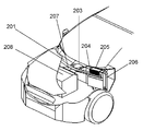
- FIG. 2 is a partially transparent perspective view of a vehicle equipped with the vehicle air conditioner according to the present embodiment.
- the sensible heat exchanger unit 205 is disposed on the upper part of the intake duct lower member 201 constituting the intake duct.
- the sensible heat exchanger unit 205 introduces engine room air warmed by the engine 208 through an opening provided in the intake duct lower member 201.
- Air from the engine room passes through the air guide plate 207 provided in the engine room, the sirocco fan 203 provided on the intake duct lower member 201, and the inside air introduction duct 204, and the sensible heat exchanger included in the sensible heat exchanger unit 205. To the first heat exchange channel.
- the air heat-exchanged in the first heat exchange channel is discharged out of the vehicle from the discharge port provided on the back side of the fender of the inside air discharge duct 206.
- the inside air discharge duct 206 passes through a discharge port (not shown) for discharging water in the intake duct of the intake duct to the outside of the vehicle.
- a negative pressure acts on the discharge port of the inside air discharge duct 206 provided on the back side of the fender, and the action of sucking air from the engine room to the sensible heat exchanger unit 205 works.
- the opening provided in the intake duct lower member 201 corresponds to the opening 105 provided in the intake duct in order to constitute the first air flow path in FIG.
- the air guide plate 207 provided in the engine room corresponds to the radiant heat recovery unit 101 provided at the inlet of the first air flow path in FIG.
- the sirocco fan 203 corresponds to the blower fan 102 located in the first air flow path in FIG.
- the inlet of the first air flow path, the sirocco fan 203, the internal air introduction duct 204, the first heat exchange flow path, and the internal air discharge duct 206 constitute the first air flow path in FIG.
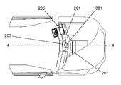
- FIG. 3 is a plan view of a vehicle equipped with the vehicle air conditioner according to the present embodiment as viewed from above the vehicle.
- the air guide plate 207 below the air guide plate 207 is an exhaust pipe that is a passage for air burned by the engine, and the air guide plate 207 is disposed so as to cover the exhaust pipe.
- An opening 301 is provided below the sirocco fan 203.
- the opening 301 provided in the intake duct lower member 201 has a rectangular plane formed by a line segment in which the exhaust pipe is projected rearward from the front surface of the vehicle along the axle and a line segment passing through the opening and parallel to the line segment. It is provided in the position.
- the opening 301 is provided at the upper portion of the exhaust pipe.
- the opening 301 is provided at the above position, the first air flow path can be obtained by using the air heated by the exhaust pipe and the air introduced into the engine room by traveling of the vehicle even in the configuration without the air guide plate. It is possible to easily introduce to.
- the sensible heat exchanger unit 205 is opposite to the external air flow inlet so that the outside air introduced into the intake duct can be introduced into the second heat exchange channel of the sensible heat exchanger included in the sensible heat exchanger unit 205. It is installed so that the side is isolated from the intake duct. That is, the sensible heat exchanger unit 205 is arranged in the intake duct so that a space exists in the vehicle forward direction of the sensible heat exchanger unit 205.
- FIG. 4 is a cross-sectional view taken along line 4-4 shown in FIG. 4, the air guide plate 207 has an opening in the direction of the engine 208, and has a box shape in which the opening width in the front-rear direction of the vehicle increases from the inlet 401 of the first air flow path toward the engine 208. ing.
- the air guide plate 207 is disposed so as to cover the plurality of exhaust pipes 402 located in the immediate vicinity of the engine.
- the air guide plate 207 collects air in the engine room heated by the radiant heat of the exhaust pipe 402 and guides it to the inlet 401 of the first air flow path.
- the air guide plate 207 is made of stainless steel or iron plate, which is a material that is difficult to deform against heat.
- the intake of air from the engine room is performed by the suction force of the sirocco fan 203.
- FIG. 5 is a view showing the vicinity of the sensible heat exchanger unit 205 of the intake duct in which the sensible heat exchanger unit 205 according to the present embodiment is arranged.
- the sensible heat exchanger unit 205 is arranged in the internal space of the intake duct.
- the intake duct includes an intake duct lower member 201, an intake duct upper member 501, a part of the body frame (not shown), and a part of the body frame 503.
- the intake duct upper member 501 covers the intake duct lower member 201.
- a part of the vehicle body frame is in contact with the intake duct lower member 201 and the intake duct upper member 501, and forms a polygonal tube together with the intake duct lower member 201 and the intake duct upper member 501.
- Parts 503 of the vehicle body frame are provided on both sides of the polygonal pipe and constitute the side surface of the intake duct.
- the intake duct upper member 501 has an inclined surface 501a.
- the inclined surface 501a is provided with a plurality of openings (not shown) for taking outside air into the intake duct.
- FIG. 6 is a view in which the intake duct upper member 501 is removed from FIG.
- the sensible heat exchanger unit 205 and the air flow path are shown.
- the sensible heat exchanger unit 205 disposed in the internal space of the intake duct is configured to move the outside air taken into the intake duct from the opening of the intake duct upper member 501 through the second heat exchange channel of the sensible heat exchanger. It is connected to an outside air introduction duct 502 introduced into the room.
- the outside air introduction duct 502 is connected to a sirocco fan 504 provided in the passenger compartment through an outside air flow inlet (not shown) of the intake duct.
- the second heat exchange channel of the sensible heat exchanger and the outside air introduction duct 502 constitute the second air channel in FIG.
- the sirocco fan 504 corresponds to the blower fan 104 in FIG.
- a discharge port for discharging water in the intake duct to the outside of the vehicle is provided in a part 503 of the vehicle body frame that forms the side surface of the intake duct.
- the inside air discharge duct 206 of the first air flow path passes through this outlet and discharges inside air to the outside of the vehicle.
- a discharge port included in a part 503 of the body frame corresponds to the opening 109 in FIG.
- the sensible heat exchanger unit 205 includes a case 601 and a sensible heat exchanger in the case.
- the case 601 is provided with an air intake.
- a plurality of intakes are individually provided so that the air in the first heat exchange channel and the second heat exchange channel of the sensible heat exchanger is not mixed.
- Air from the engine room is introduced into one intake port of the case 601 by the inside air introduction duct 204.
- the air introduced from the intake port exchanges heat with the air in the air passage B flowing through the second heat exchange passage through the first heat exchange passage of the sensible heat exchanger, and the air after the heat exchange is the inside air discharge duct. It passes through 206 and is discharged out of the vehicle.
- the air path B is an air path generated in a space between the sensible heat exchanger unit 205 and the intake duct.
- the air introduced into the intake duct is an air passage that is introduced into the second heat exchange passage of the sensible heat exchanger.
- the air introduced into the second heat exchange channel exchanges heat with the air in the first heat exchange channel.
- the air after heat exchange is introduced into the vehicle interior by the outside air introduction duct 502 via the outside air flow inlet of the intake duct.
- the intake of air from the intake duct into the passenger compartment is performed by the suction force of the sirocco fan 504 provided in the passenger compartment.
- FIG. 7 is a cross-sectional view taken along line 7-7 shown in FIG.
- the cross section indicated by reference signs a to b is the intake duct lower member 201.
- An intake duct upper member 501 covering the intake duct lower member 201 is a cross section indicated by reference signs a to c.
- the inclined surface 501a of the intake duct upper member is provided with a plurality of openings for taking outside air into the intake duct.
- An external airflow inlet 704 is provided in a part 701 of the vehicle body frame constituting the intake duct.
- the sensible heat exchanger unit 205 is opposite to the external air flow inlet so that the outside air introduced into the intake duct can be introduced into the second heat exchange channel of the sensible heat exchanger included in the sensible heat exchanger unit 205. It is installed so that the side is isolated from the intake duct.
- the outside air introduced into the intake duct from the opening of the inclined surface 501a passes through the space between the intake duct and the surface on the opposite side of the sensible heat exchanger unit 205 with respect to the external air flow inlet, and the second air of the sensible heat exchanger. It is introduced into the heat exchange flow path.
- the air heat-exchanged in the second heat exchange flow path is introduced into the vehicle interior by the outside air introduction duct 502 via the outside air flow inlet 704 included in the intake duct.
- the air introduced into the vehicle interior is delivered to the existing HAVC mechanism by a sirocco fan 504 provided in the vehicle interior connected to the outlet of the outside air introduction duct 502.
- the existing HAVC mechanism has various air conditioning functions such as an electric heater.
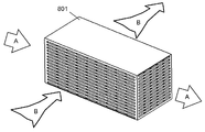
- FIG. 8 is a diagram showing a configuration of the sensible heat exchanger 801 in the present embodiment.
- the sensible heat exchanger 801 is disposed in the case 601 of the sensible heat exchanger unit 205.
- the sensible heat exchanger 801 is a stationary heat exchanger with a fixed flow path. It has a first heat exchange channel and a second heat exchange channel, and is adjacent to each other with a thermally conductive partition.
- the heat exchange is performed between the air from the engine room flowing through the first heat exchange flow path and the air introduced into the intake duct flowing through the second heat exchange flow path via the heat conductive partition.
- the sensible heat exchanger 801 in which the opening 105 is provided in the intake duct and the air heated by the heat generated from the engine room is arranged in the internal space of the intake duct.
- the configuration in which the sirocco fan is provided in the first air flow path has been described.
- the engine room air is supplied only by the negative pressure at the discharge port of the first air flow path provided on the back side of the fender. You may make it introduce.
- a sensible heat exchanger has been described as a heat exchanger, a total heat exchanger or the like may be used and is not limited to a sensible heat exchanger.
- the intake duct lower member 201, the intake duct upper member 501, a polygonal pipe formed by a part 701 of the body frame, and the body frame on both sides of the polygonal pipe are used as the intake duct.
- the intake duct composed of a part 503
- the shape of the intake duct, the members constituting the intake duct, and the number of members are examples, and the configuration of the intake duct is not limited to these. Absent.
- the present invention is suitable as an air conditioner for a vehicle such as an automobile that uses heat generated by an engine.
Landscapes
- Engineering & Computer Science (AREA)
- Mechanical Engineering (AREA)
- Physics & Mathematics (AREA)
- Thermal Sciences (AREA)
- Chemical & Material Sciences (AREA)
- Combustion & Propulsion (AREA)
- General Engineering & Computer Science (AREA)
- Air-Conditioning For Vehicles (AREA)
- Body Structure For Vehicles (AREA)
Abstract
車両用空調装置は、熱交換器と、第1の空気流路と、第2の空気流路とを有する。熱交換器は、車室の外に設けられた開口を有するインテークダクトの内部空間に配置されている。この熱交換器、第1の熱交換流路と第2の熱交換流路とを有し、第1の熱交換流路に流れる空気と第2の熱交換流路に流れる空気との間で熱交換する。第1の空気流路は、エンジンから発せられる熱によって加熱された空気を、インテークダクトの開口を介して第1の熱交換流路に導入し、第1の熱交換流路から車外へ排出する。第2の空気流路は、第2の熱交換流路に導入された外気を、インテークダクトの外気流入口を介して車室の中へ導入する。 上記構成により、熱交換器を設置する専用のスペースを新たに確保することなく、既存のスペースを活用し、エンジンルームの熱を利用した車両用空調装置を提供する。
Description
本発明は、エンジンルームの熱を利用した車両用空調装置に関する。
従来のエンジンルームの熱を利用した車両用空調装置としては、エンジンルーム内に導入口と排出口とを有する送風通路を、車室内に設置した熱交換器と連結させ、熱交換器で温めた空気を、エンジンの冷却水と熱交換する主熱交換器で温めるものが知られている(特許文献1)。
本発明は、熱交換器を設置する専用のスペースを新たに確保することなく、既存のスペースを活用し、エンジンルームの熱を利用した車両用空調装置を提供する。
本発明の車両用空調装置は、熱交換器と、第1の空気流路と、第2の空気流路とを有する。熱交換器は、車室の外に設けられた開口を有するインテークダクトの内部空間に配置されている。この熱交換器は、第1の熱交換流路と第2の熱交換流路とを有し、第1の熱交換流路に流れる空気と第2の熱交換流路に流れる空気との間で熱交換する。第1の空気流路は、エンジンから発せられる熱によって加熱された空気を、インテークダクトの開口を介して第1の熱交換流路に導入し、第1の熱交換流路から車外へ排出する。第2の空気流路は、第2の熱交換流路に導入された外気を、インテークダクトの外気流入口を介して車室の中へ導入する。
このように、車室外に設けられたインテークダクトに開口を設け、エンジンルームから発せられる熱によって加熱された空気をインテークダクトの内部空間に配置した熱交換器へ導入する。この構成により、熱交換器を設置する専用のスペースを新たに確保することなく、エンジンルームの熱を利用することができる。
本発明の実施の形態の説明に先立ち、従来の車両用空調装置における問題点を説明する。従来技術におけるエンジンルームの熱を利用した車両用空調装置では、熱交換器を設置する専用のスペースを車室内に新たに確保する必要がある。
以下、本発明の実施の形態における車両用空調装置について図面を用いて説明する。図1は、本発明の実施の形態における車両用空調装置の構成を示す概念図である。
輻射熱回収部101は、エンジンルーム内に設置され、エンジンからの輻射熱を回収する。輻射熱回収部101は、第1の空気流路の導入口に設けられ、エンジによって温められたエンジンルームの空気を回収し、第1の空気流路へ導入する。
第1の空気流路内に位置するブロアファン102は、エンジンルームから空気を取り入れ、同じく第1の空気流路内に位置する熱交換器103へ送る。
熱交換器103は、第1の熱交換流路と第2の熱交換流路と有し、第1の熱交換流路に流れる空気と第2の熱交換流路に流れる空気との間で熱交換を行う。
ブロアファン102により、エンジンルームから導入した空気は、熱交換器103の第1の熱交換流路へ導入される。熱交換器103の第1の熱交換流路は第1の空気流路を構成する。熱交換された空気は、第1の空気流路の排出口106から車外へ排出される。
第1の空気流路の排出口106は、フェンダーの裏側に位置している。フェンダーの裏側に位置する排出口106には負圧が働き、エンジンルームから第1の空気流路へ空気を導く吸引力が第1の空気流路内に生じる。
図1において、インテークダクト108は破線で表されている。インテークダクトとは、車室外に設けられ、車外の空気(外気)を車室内へ取り入れるダクトである。ウインドシールドガラスの前方で、かつ、ウインドシールドガラスとフードパネルとの間に位置する車幅方向に延びたダクトである。
インテークダクトは、インテークダクト内に車外の空気を取り入れるための開口部と、インテークダクト内に取り入れた車外の空気を車室内へ取り入れるための外気流入口を有している。また、インテークダクトは、インテークダクト内の水を車外へ排出するための排出口を有している。インテークダクトは、熱交換器103を設置するための十分な空間を有している。
図1において外気流入口107はインテークダクト108が有している開口である。開口105は、第1の空気流路を構成するためにインテークダクト108に設けた開口である。開口109は、インテークダクト内の水を車外に排出するためにインテークダクト108が有している開口である。
インテークダクトに取り込んだ外気は、熱交換器103の第2の熱交換流路に導入される。熱交換器103の第2の熱交換流路は第2の空気流路を構成する。第1の熱交換路を通る空気と熱交換を行った第2の熱交換流路の空気は、インテークダクトが有している外気流入口107を介して車室内に導入される。車室内に導入された空気は、第2の空気流路の排出口に接続された車室内に設けられたブロアファン104により、既設のHVAC(Heating,Ventilation,and Air Conditioning)機構へ受け渡される。
以上のように本実施の形態による車両用空調装置は、エンジンルームから発せられる熱によって加熱された空気をインテークダクトに設けた開口105を介して第1の熱交換流路に導入し、第1の熱交換流路から車外へ排出する第1の空気流路と、第2の熱交換流路に導入された外気をインテークダクトの外気流入口107を介して車室内へ導入する第2の空気流路を有している。
本実施の形態による車両用空調装置は、第1の空気流路の導入口にエンジンからの輻射熱を回収する輻射熱回収部101を有している。
本実施の形態による車両用空調装置は、第1の空気流路の導入口と第1の熱交換流路との間にエンジンルーム内の空気を第1の熱交換流路へ送る第一のブロアファン102を有している。
本実施の形態による車両用空調装置は、第1の空気流路の排出口がフェンダーの裏側に位置している。
本実施の形態による車両用空調装置は、第2の空気流路の排出口が車室内に設けられた第二のブロアファン104に接続されている。
本実施の形態による車両用空調装置は、第1の熱交換流路と第2の熱交換流路と有し、第1の熱交換流路に流れる空気と第2の熱交換流路に流れる空気との間で熱交換する熱交換器103をインテークダクト内の既存スペースに配置した構成となっている。
以下、本実施の形態による車両用空調装置の具体的な構造について図面を用いて説明する。
図2は、本実施の形態による車両用空調装置を搭載した車両の部分透視斜視図である。
顕熱交換器ユニット205は、インテークダクトを構成するインテークダクト下部部材201の上部に配置されている。顕熱交換器ユニット205は、エンジン208により温められたエンジンルームの空気を、インテークダクト下部部材201に設けた開口を介して導入する。
エンジンルームからの空気は、エンジンルーム内に設けた導風板207、インテークダクト下部部材201上に設けたシロッコファン203、内気導入ダクト204を通り、顕熱交換器ユニット205が有する顕熱交換器の第1の熱交換流路に導入される。
第1の熱交換流路で熱交換された空気は、内気排出ダクト206のフェンダーの裏側に設けた排出口から車外へ排出される。内気排出ダクト206は、インテークダクトが有するインテークダクト内の水を車外へ排出するための排出口(図示せず)を通る。
フェンダーの裏側に設けた内気排出ダクト206の排出口には負圧が働き、エンジンルームから顕熱交換器ユニット205へ空気を吸引する作用が働く。
インテークダクト下部部材201に設けた開口は、図1における第1の空気流路を構成するためにインテークダクトに設けた開口105に相当する。エンジンルーム内に設けた導風板207は、図1における、第1の空気流路の導入口に設けられた輻射熱回収部101に相当する。シロッコファン203は、図1における第1の空気流路内に位置するブロアファン102に相当する。
第1の空気流路の導入口、シロッコファン203、内気導入ダクト204、第1の熱交換流路、内気排出ダクト206が図1における第1の空気流路を構成する。
図3は、本実施の形態による車両用空調装置を搭載した車両を車両上部から見た平面図である。
導風板207の下にはエンジンで燃焼された空気の通路であるエキゾーストパイプがあり、導風板207はエキゾーストパイプを覆うように配置されている。また、シロッコファン203の下側には開口301がある。インテークダクト下部部材201に設けた開口301は、エキゾーストパイプを車両の前面から車軸に沿って後方に投影した線分と、開口を通りこの線分と平行な線分とが構成する平面が長方形となる位置に設けられている。
即ち、エキゾーストパイプを車軸方向に平行移動した場合に、エキゾーストパイプの上部に開口301が位置するように設けられている。
開口301が上記の位置に設けられることにより、導風板を有しない構成においても、エキゾーストパイプにより温められた空気を、車両の走行によってエンジンルームに導入される空気により、第1の空気流路へ容易に導入することが可能となる。
顕熱交換器ユニット205は、インテークダクトに導入された外気が、顕熱交換器ユニット205が有する顕熱交換器の第2の熱交換流路に導入可能なように、外気流入口に対する反対の側がインテークダクトと隔離するように設置されている。即ち、インテークダクト内において、顕熱交換器ユニット205の車両前方方向に空間が存在するように、顕熱交換器ユニット205が配置されている。
図4は、図3に示す4-4線における断面図である。図4において、導風板207は、エンジン208方向に開口を有し、車両の前後方向の開口幅が第1の空気流路の導入口401からエンジン208に向かい増大する箱型の形状をしている。
導風板207は、エンジンの直近に位置する複数のエキゾーストパイプ402を覆うように配置されている。導風板207は、エキゾーストパイプ402の輻射熱により温められたエンジンルーム内の空気を回収し、第1の空気流路の導入口401へ誘導する。導風板207は、熱に対し変形しにくい素材であるステンレスや鉄板により構成される。
エンジンルームからの空気の取り入れは、シロッコファン203の吸引力により行われる。
図5は、本実施の形態による顕熱交換器ユニット205が配置されたインテークダクトの顕熱交換器ユニット205の近傍を示す図である。図5において顕熱交換器ユニット205は、インテークダクトの内部空間に配置されている。
本実施の形態において、インテークダクトは、インテークダクト下部部材201と、インテークダクト上部部材501と、車体フレームの一部(図示せず)と、車体フレームの一部503とにより構成されている。インテークダクト上部部材501は、インテークダクト下部部材201を覆っている。車体フレームの一部は、インテークダクト下部部材201とインテークダクト上部部材501とに接し、インテークダクト下部部材201とインテークダクト上部部材501とともに多角形状の管を形成している。車体フレームの一部503は、この多角形状の管の両側に設けられ、インテークダクトの側面を構成している。
インテークダクト上部部材501は傾斜面501aを有する。傾斜面501aには、外気をインテークダクト内に取り入れるための開口部が複数設けられている(図示せず)。
図6は、図5からインテークダクト上部部材501を取り除いた図である。顕熱交換器ユニット205と空気流路を示している。
インテークダクトの内部空間に配置された顕熱交換器ユニット205は、インテークダクト上部部材501の開口部からインテークダクト内に取り入れた外気を顕熱交換器の第2の熱交換流路を介して車室内に導入する外気導入ダクト502と接続している。
外気導入ダクト502は、インテークダクトが有する外気流入口(図示せず)を通り、車室内に設けられたシロッコファン504に接続されている。
顕熱交換器の第2の熱交換流路と外気導入ダクト502は図1における第2の空気流路を構成する。シロッコファン504は図1のブロアファン104に相当する。
インテークダクトの側面を構成する車体フレームの一部503には、インテークダクト内の水を車外に排出するための排出口が設けられている。第1の空気流路の内気排出ダクト206は、この排出口を通り、内気を車外へ排出する。車体フレームの一部503が有する排出口が、図1における開口109に相当する。
顕熱交換器ユニット205は、ケース601とケース内の顕熱交換機により構成される。ケース601には、空気の取り入れ口が設けられている。この取り入れ口は、顕熱交換機の第1の熱交換流路と第2の熱交換流路の空気とが混合しないように個別に複数設けられている。
図6に示す空気流路Aは、エンジンルームからの空気が流れる第1の空気流路である。エンジンルームからの空気は内気導入ダクト204により、ケース601の一方の取り入れ口に導入される。取り入れ口から導入された空気は顕熱交換機の第1の熱交換流路により、第2の熱交換流路を流れる空気路Bの空気と熱交換を行い、熱交換後の空気は内気排出ダクト206を通り車外へ排出される。
空気路Bは、顕熱交換器ユニット205とインテークダクトとの間の空間に生じる空気路である。インテークダクトに導入された空気が、顕熱交換器の第2の熱交換流路に導入される空気路である。第2の熱交換流路に導入された空気は、第1の熱交換流路の空気との間で熱交換を行う。熱交換後の空気は、外気導入ダクト502によりインテークダクトの外気流入口を介して車室内へ導入される。
インテークダクトからの車室内への空気の取り入れは、車室内に設けられたシロッコファン504の吸引力により行われる。
図7は、図5に示す7-7線における断面図である。符号a~符号bによって示される断面がインテークダクト下部部材201である。インテークダクト下部部材201を覆うインテークダクト上部部材501は、符号a~符号cが示す断面である。インテークダクト上部部材の傾斜面501aには、外気をインテークダクト内に取り入れるための開口部が複数設けられている。
符号c~符号bで示す断面が、インテークダクト下部部材201とインテークダクト上部部材501とに接し、インテークダクト下部部材201とインテークダクト上部部材501とで多角形状の管を形成する車体フレームの一部701である。
インテークダクトを構成する車体フレームの一部701には、外気流入口704が設けられている。
顕熱交換器ユニット205は、インテークダクトに導入された外気が、顕熱交換器ユニット205が有する顕熱交換器の第2の熱交換流路に導入可能なように、外気流入口に対する反対の側がインテークダクトと隔離するように設置されている。
傾斜面501aの開口部からインテークダクト内に導入された外気は、インテークダクトと顕熱交換器ユニット205の外気流入口に対する反対側の面との間の空間を通り、顕熱交換器の第2の熱交換流路に導入される。
第2の熱交換流路で熱交換された空気は、インテークダクトが有する外気流入口704を介して、外気導入ダクト502により車室内に導入される。車室内に導入された空気は、外気導入ダクト502の排出口に接続された車室内に設けられたシロッコファン504により、既設のHAVC機構へ受け渡される。既設のHAVC機構は、電気ヒータ等の各種の空調機能を有している。
図8は、本実施の形態における顕熱交換器801の構成を示す図である。顕熱交換器801は、顕熱交換器ユニット205のケース601内に配置される。顕熱交換器801は、流路が固定された静止型の熱交換機である。第1の熱交換流路と第2の熱交換流路を有し、互いに伝熱性の隔壁を隔て隣接している。
第1の熱交換流路を流れるエンジンルームからの空気と第2の熱交換流路を流れるインテークダクトに導入された空気との間で、伝熱性の隔壁を介して熱交換が行われる。
以上のようの本実施の形態による車両空調装置によれば、インテークダクトに開口105を設け、エンジンルームから発せられる熱によって加熱された空気をインテークダクトの内部空間に配置した顕熱交換器801へ導入することにより、顕熱交換器801を設置する専用のスペースを新たに確保することなく、エンジンルームの熱を利用した車両用空調装置を提供することができる。
なお、実施の形態では第1の空気流路内にシロッコファンを設けた構成を説明したが、フェンダーの裏側に設けた第1の空気流路の排出口の負圧のみでエンジンルームの空気を導入するようにしてもよい。
また、熱交換器として顕熱交換器を用いて説明したが、全熱交換機等を用いてもよく、顕熱交換器に限定されるものではない。
また、本実施の形態では、インテークダクトとして、インテークダクト下部部材201とインテークダクト上部部材501、車体フレームの一部701により構成される多角形状の管と、多角形状の管の両側の車体フレームの一部503から構成されるインテークダクトを用いて説明したが、インテークダクトの形状や、インテークダクトを構成する部材、また部材の数は一例であり、インテークダクトの構成がこれらに限定されるものではない。
実施の形態における説明は一例であり、本発明は、その要旨を逸脱しない範囲内において種々の変更が可能である。
本発明は、エンジンが発する熱を利用する自動車等の車両用空調装置として好適である。
101 輻射熱回収部
102 ブロアファン
103 熱交換器
104 ブロアファン
105 開口
106 排出口
107 外気流入口
108 インテークダクト
109 開口
201 インテークダクト下部部材
203 シロッコファン
204 内気導入ダクト
205 顕熱交換器ユニット
206 内気排出ダクト
207 導風板
208 エンジン
301 開口
401 導入口
402 エキゾーストパイプ
501 インテークダクト上部部材
501a 傾斜面
502 外気導入ダクト
503 車体フレームの一部
504 シロッコファン
601 ケース
701 車体フレームの一部
704 外気流入口
801 顕熱交換器
102 ブロアファン
103 熱交換器
104 ブロアファン
105 開口
106 排出口
107 外気流入口
108 インテークダクト
109 開口
201 インテークダクト下部部材
203 シロッコファン
204 内気導入ダクト
205 顕熱交換器ユニット
206 内気排出ダクト
207 導風板
208 エンジン
301 開口
401 導入口
402 エキゾーストパイプ
501 インテークダクト上部部材
501a 傾斜面
502 外気導入ダクト
503 車体フレームの一部
504 シロッコファン
601 ケース
701 車体フレームの一部
704 外気流入口
801 顕熱交換器
Claims (9)
- 車室とエンジンとを有する車両に搭載される車両用空調装置であって、
前記車室の外に設けられた開口を有するインテークダクトの内部空間に配置され、第1の熱交換流路と第2の熱交換流路とを有し、前記第1の熱交換流路に流れる空気と前記第2の熱交換流路に流れる空気との間で熱交換する熱交換器と、
前記エンジンから発せられる熱によって加熱された空気を、前記インテークダクトの前記開口を介して前記第1の熱交換流路に導入し、前記第1の熱交換流路から車外へ排出する第1の空気流路と、
前記第2の熱交換流路に導入された外気を、前記インテークダクトの外気流入口を介して前記車室の中へ導入する第2の空気流路と、を備えた、
車両用空調装置。 - 前記第1の空気流路の導入口に設けられ、前記エンジンからの輻射熱を回収する輻射熱回収部をさらに備えた、
請求項1に記載の車両用空調装置。 - 前記輻射熱回収部は、前記エンジンの方向に開口を有し、前記車両の前後方向の開口幅が前記第1の空気流路の前記導入口から前記エンジンに向かい増大する箱型の形状を有する導風板を含む、
請求項2に記載の車両用空調装置。 - 前記第1の空気流路の前記導入口と前記第1の熱交換流路との間に設けられ、前記エンジンが収納されたエンジンルーム内の空気を前記第1の熱交換流路へ送る第1のブロアファンをさらに備えた、
請求項1から請求項3のいずれか1項に記載の車両用空調装置。 - 前記熱交換器における、前記外気流入口の反対側が前記インテークダクトと隔離するように、前記熱交換器が設置された、
請求項1から請求項4のいずれか1項に記載の車両用空調装置。 - 前記第1の空気流路の排出口が、前記車両のフェンダーの裏側に位置している、
請求項1から請求項5のいずれか1項に記載の車両用空調装置。 - 前記車室の内部に設けられた第2のブロアファンをさらに備え、
前記第2の空気流路の排出口が前記第2のブロアファンに接続されている、
請求項1から請求項6のいずれか1項に記載の車両用空調装置。 - 前記エンジンで燃焼された空気の通路であるエキゾーストパイプを前記車両の前面から車軸に沿って後方に投影した線分と、前記インテークダクトに設けられた前記開口を通り前記線分と平行な線分とが構成する平面が長方形となる位置に、前記インテークダクトの前記開口が設けられた、
請求項1から請求項7のいずれか1項に記載の車両用空調装置。 - 前記熱交換器は顕熱交換器である、
請求項1から請求項8のいずれか1項に記載の車両用空調装置。
Priority Applications (2)
| Application Number | Priority Date | Filing Date | Title |
|---|---|---|---|
| EP15751485.2A EP3109074A4 (en) | 2014-02-19 | 2015-02-18 | Air-conditioning device for vehicle |
| US15/226,805 US20160339762A1 (en) | 2014-02-19 | 2016-08-02 | Air-conditioning device for vehicle |
Applications Claiming Priority (2)
| Application Number | Priority Date | Filing Date | Title |
|---|---|---|---|
| JP2014029221A JP2015151099A (ja) | 2014-02-19 | 2014-02-19 | 車両用空調装置 |
| JP2014-029221 | 2014-02-19 |
Related Child Applications (1)
| Application Number | Title | Priority Date | Filing Date |
|---|---|---|---|
| US15/226,805 Continuation US20160339762A1 (en) | 2014-02-19 | 2016-08-02 | Air-conditioning device for vehicle |
Publications (1)
| Publication Number | Publication Date |
|---|---|
| WO2015125474A1 true WO2015125474A1 (ja) | 2015-08-27 |
Family
ID=53877993
Family Applications (1)
| Application Number | Title | Priority Date | Filing Date |
|---|---|---|---|
| PCT/JP2015/000755 Ceased WO2015125474A1 (ja) | 2014-02-19 | 2015-02-18 | 車両用空調装置 |
Country Status (4)
| Country | Link |
|---|---|
| US (1) | US20160339762A1 (ja) |
| EP (1) | EP3109074A4 (ja) |
| JP (1) | JP2015151099A (ja) |
| WO (1) | WO2015125474A1 (ja) |
Cited By (1)
| Publication number | Priority date | Publication date | Assignee | Title |
|---|---|---|---|---|
| CN109835135A (zh) * | 2017-11-28 | 2019-06-04 | 现代自动车株式会社 | 用于车辆的热交换器 |
Families Citing this family (6)
| Publication number | Priority date | Publication date | Assignee | Title |
|---|---|---|---|---|
| US10272744B2 (en) * | 2015-09-03 | 2019-04-30 | Ford Global Technologies, Llc | Vehicle HVAC system with auxiliary coolant loop for heating and cooling vehicle interior |
| JP6858457B2 (ja) * | 2016-09-22 | 2021-04-14 | マレリキャビンコンフォートジャパン株式会社 | 車両用の空調装置 |
| GB201707161D0 (en) * | 2017-02-02 | 2017-06-21 | Tata Motors European Technical Ct Plc | A grille shutter assembly |
| CN108891488B (zh) * | 2018-07-25 | 2020-11-20 | 浙江三宝知识产权服务有限公司 | 具有清雪功能的汽车 |
| CN113086021A (zh) * | 2021-05-11 | 2021-07-09 | 中国华冶科工集团有限公司 | 轮胎防滑辅助加热装置及其方法 |
| DE102023103581A1 (de) | 2023-02-14 | 2024-08-14 | Ford Global Technologies, Llc | Luftleitvorrichtung für ein Klimagerät eines zumindest teilweise elektrisch angetriebenen Fahrzeugs, System, Verfahren zum Betreiben eines Systems und Fahrzeug |
Citations (4)
| Publication number | Priority date | Publication date | Assignee | Title |
|---|---|---|---|---|
| JPS57124408U (ja) * | 1981-01-29 | 1982-08-03 | ||
| JPS60106818U (ja) * | 1983-12-27 | 1985-07-20 | カルソニックカンセイ株式会社 | セラミツクエンジン塔載車用空調機の温度制御装置 |
| JP2008174085A (ja) * | 2007-01-18 | 2008-07-31 | Toyota Motor Corp | 車両用シートの蓄熱装置 |
| JP2013193636A (ja) * | 2012-03-22 | 2013-09-30 | Panasonic Corp | 車両の外気導入構造 |
Family Cites Families (9)
| Publication number | Priority date | Publication date | Assignee | Title |
|---|---|---|---|---|
| DE1131110B (de) * | 1962-06-07 | Porsche Kg | Einrichtung zum Heizen und Belueften eines durch eine luftgekuehlte Brennkraftmaschine betriebenen Kraftfahrzeugs | |
| JPS5974109U (ja) * | 1982-11-12 | 1984-05-19 | 日産自動車株式会社 | 自動車用暖房装置 |
| DE3343076A1 (de) * | 1983-11-29 | 1985-06-05 | Robert Bosch Gmbh, 7000 Stuttgart | Vorrichtung zur innenraumbeheizung und motorkuehlung eines kraftfahrzeugs |
| JP3834959B2 (ja) * | 1997-10-13 | 2006-10-18 | 株式会社デンソー | 車両用空気調和装置 |
| FR2775221B1 (fr) * | 1998-02-20 | 2000-05-26 | Renault | Dispositif d'aeration, de chauffage et de climatisation d'un habitacle d'un vehicule automobile |
| US6484755B1 (en) * | 1999-03-31 | 2002-11-26 | Valeo Climate Control Inc. | Blend door actuation for dual zone |
| JP2000301933A (ja) * | 1999-04-16 | 2000-10-31 | Mitsubishi Heavy Ind Ltd | エアミックスダンパ装置及び車両用空気調和装置 |
| US6332497B1 (en) * | 1999-06-07 | 2001-12-25 | Mitsubishi Heavy Industries, Ltd. | Vehicular air conditioner |
| US6827141B2 (en) * | 2001-02-23 | 2004-12-07 | International Truck Intellectual Property Company, Llc | Vehicle heating and air conditioning modules |
-
2014
- 2014-02-19 JP JP2014029221A patent/JP2015151099A/ja active Pending
-
2015
- 2015-02-18 WO PCT/JP2015/000755 patent/WO2015125474A1/ja not_active Ceased
- 2015-02-18 EP EP15751485.2A patent/EP3109074A4/en not_active Withdrawn
-
2016
- 2016-08-02 US US15/226,805 patent/US20160339762A1/en not_active Abandoned
Patent Citations (4)
| Publication number | Priority date | Publication date | Assignee | Title |
|---|---|---|---|---|
| JPS57124408U (ja) * | 1981-01-29 | 1982-08-03 | ||
| JPS60106818U (ja) * | 1983-12-27 | 1985-07-20 | カルソニックカンセイ株式会社 | セラミツクエンジン塔載車用空調機の温度制御装置 |
| JP2008174085A (ja) * | 2007-01-18 | 2008-07-31 | Toyota Motor Corp | 車両用シートの蓄熱装置 |
| JP2013193636A (ja) * | 2012-03-22 | 2013-09-30 | Panasonic Corp | 車両の外気導入構造 |
Non-Patent Citations (1)
| Title |
|---|
| See also references of EP3109074A4 * |
Cited By (1)
| Publication number | Priority date | Publication date | Assignee | Title |
|---|---|---|---|---|
| CN109835135A (zh) * | 2017-11-28 | 2019-06-04 | 现代自动车株式会社 | 用于车辆的热交换器 |
Also Published As
| Publication number | Publication date |
|---|---|
| EP3109074A1 (en) | 2016-12-28 |
| EP3109074A4 (en) | 2017-03-15 |
| JP2015151099A (ja) | 2015-08-24 |
| US20160339762A1 (en) | 2016-11-24 |
Similar Documents
| Publication | Publication Date | Title |
|---|---|---|
| JP2015151099A (ja) | 車両用空調装置 | |
| US20070218824A1 (en) | Partial recirculation vehicle HVAC system | |
| JPH1071828A (ja) | 送風ユニット | |
| CN104097486A (zh) | 具有柔性叶片的空气管道组件 | |
| JP2010076506A (ja) | 車両用空気調和装置 | |
| JP3282623B2 (ja) | 送風ユニット | |
| JP5507602B2 (ja) | 車両の外気導入構造 | |
| JP4894447B2 (ja) | 車両用空調装置 | |
| KR20210058934A (ko) | 자동차용 열 교환기 모듈 | |
| JP2013014324A (ja) | フットベントを備えた空調装置 | |
| JPH1016531A (ja) | 車両用空調装置 | |
| CN106103150B (zh) | 车辆用空调装置 | |
| KR101345961B1 (ko) | 실내공기 흡입형 차량용 통풍시트 | |
| JP5062523B2 (ja) | 自動車用シート空調装置 | |
| CN105555561B (zh) | 双区域类型的机动车辆空调装置 | |
| CN105658453B (zh) | 在底部处具有减小的体积的机动车辆空调装置 | |
| JP2002307935A (ja) | 車両用空調装置 | |
| CN104981364B (zh) | 供暖、通风和/或空调设备 | |
| KR102135274B1 (ko) | 차량용 공조장치 | |
| JP3700258B2 (ja) | 車両用空調装置 | |
| JP2014111454A (ja) | 車両の外気導入構造 | |
| JP2015093515A (ja) | 車両用空調装置 | |
| WO2010150334A1 (ja) | 空調ユニットの配設構造 | |
| KR100410783B1 (ko) | 버스 후방 승객석 난방장치 | |
| JP2010126137A (ja) | 車両用送風装置 |
Legal Events
| Date | Code | Title | Description |
|---|---|---|---|
| 121 | Ep: the epo has been informed by wipo that ep was designated in this application |
Ref document number: 15751485 Country of ref document: EP Kind code of ref document: A1 |
|
| REEP | Request for entry into the european phase |
Ref document number: 2015751485 Country of ref document: EP |
|
| WWE | Wipo information: entry into national phase |
Ref document number: 2015751485 Country of ref document: EP |
|
| NENP | Non-entry into the national phase |
Ref country code: DE |