WO2015125505A1 - エンジンの制御装置 - Google Patents
エンジンの制御装置 Download PDFInfo
- Publication number
- WO2015125505A1 WO2015125505A1 PCT/JP2015/050199 JP2015050199W WO2015125505A1 WO 2015125505 A1 WO2015125505 A1 WO 2015125505A1 JP 2015050199 W JP2015050199 W JP 2015050199W WO 2015125505 A1 WO2015125505 A1 WO 2015125505A1
- Authority
- WO
- WIPO (PCT)
- Prior art keywords
- fuel
- oil
- engine
- temperature
- control device
- Prior art date
- Legal status (The legal status is an assumption and is not a legal conclusion. Google has not performed a legal analysis and makes no representation as to the accuracy of the status listed.)
- Ceased
Links
Images








Classifications
-
- F—MECHANICAL ENGINEERING; LIGHTING; HEATING; WEAPONS; BLASTING
- F01—MACHINES OR ENGINES IN GENERAL; ENGINE PLANTS IN GENERAL; STEAM ENGINES
- F01M—LUBRICATING OF MACHINES OR ENGINES IN GENERAL; LUBRICATING INTERNAL COMBUSTION ENGINES; CRANKCASE VENTILATING
- F01M5/00—Heating, cooling, or controlling temperature of lubricant; Lubrication means facilitating engine starting
- F01M5/005—Controlling temperature of lubricant
-
- F—MECHANICAL ENGINEERING; LIGHTING; HEATING; WEAPONS; BLASTING
- F01—MACHINES OR ENGINES IN GENERAL; ENGINE PLANTS IN GENERAL; STEAM ENGINES
- F01M—LUBRICATING OF MACHINES OR ENGINES IN GENERAL; LUBRICATING INTERNAL COMBUSTION ENGINES; CRANKCASE VENTILATING
- F01M5/00—Heating, cooling, or controlling temperature of lubricant; Lubrication means facilitating engine starting
- F01M5/001—Heating
-
- F—MECHANICAL ENGINEERING; LIGHTING; HEATING; WEAPONS; BLASTING
- F02—COMBUSTION ENGINES; HOT-GAS OR COMBUSTION-PRODUCT ENGINE PLANTS
- F02D—CONTROLLING COMBUSTION ENGINES
- F02D35/00—Controlling engines, dependent on conditions exterior or interior to engines, not otherwise provided for
- F02D35/02—Controlling engines, dependent on conditions exterior or interior to engines, not otherwise provided for on interior conditions
- F02D35/025—Controlling engines, dependent on conditions exterior or interior to engines, not otherwise provided for on interior conditions by determining temperatures inside the cylinder, e.g. combustion temperatures
- F02D35/026—Controlling engines, dependent on conditions exterior or interior to engines, not otherwise provided for on interior conditions by determining temperatures inside the cylinder, e.g. combustion temperatures using an estimation
-
- F—MECHANICAL ENGINEERING; LIGHTING; HEATING; WEAPONS; BLASTING
- F02—COMBUSTION ENGINES; HOT-GAS OR COMBUSTION-PRODUCT ENGINE PLANTS
- F02D—CONTROLLING COMBUSTION ENGINES
- F02D41/00—Electrical control of supply of combustible mixture or its constituents
- F02D41/0025—Controlling engines characterised by use of non-liquid fuels, pluralities of fuels, or non-fuel substances added to the combustible mixtures
-
- H—ELECTRICITY
- H05—ELECTRIC TECHNIQUES NOT OTHERWISE PROVIDED FOR
- H05B—ELECTRIC HEATING; ELECTRIC LIGHT SOURCES NOT OTHERWISE PROVIDED FOR; CIRCUIT ARRANGEMENTS FOR ELECTRIC LIGHT SOURCES, IN GENERAL
- H05B1/00—Details of electric heating devices
- H05B1/02—Automatic switching arrangements specially adapted to apparatus ; Control of heating devices
- H05B1/0227—Applications
- H05B1/023—Industrial applications
- H05B1/0236—Industrial applications for vehicles
-
- F—MECHANICAL ENGINEERING; LIGHTING; HEATING; WEAPONS; BLASTING
- F02—COMBUSTION ENGINES; HOT-GAS OR COMBUSTION-PRODUCT ENGINE PLANTS
- F02D—CONTROLLING COMBUSTION ENGINES
- F02D41/00—Electrical control of supply of combustible mixture or its constituents
- F02D41/22—Safety or indicating devices for abnormal conditions
- F02D2041/224—Diagnosis of the fuel system
-
- F—MECHANICAL ENGINEERING; LIGHTING; HEATING; WEAPONS; BLASTING
- F02—COMBUSTION ENGINES; HOT-GAS OR COMBUSTION-PRODUCT ENGINE PLANTS
- F02D—CONTROLLING COMBUSTION ENGINES
- F02D2200/00—Input parameters for engine control
- F02D2200/02—Input parameters for engine control the parameters being related to the engine
- F02D2200/023—Temperature of lubricating oil or working fluid
-
- F—MECHANICAL ENGINEERING; LIGHTING; HEATING; WEAPONS; BLASTING
- F02—COMBUSTION ENGINES; HOT-GAS OR COMBUSTION-PRODUCT ENGINE PLANTS
- F02D—CONTROLLING COMBUSTION ENGINES
- F02D2200/00—Input parameters for engine control
- F02D2200/02—Input parameters for engine control the parameters being related to the engine
- F02D2200/06—Fuel or fuel supply system parameters
- F02D2200/0611—Fuel type, fuel composition or fuel quality
-
- F—MECHANICAL ENGINEERING; LIGHTING; HEATING; WEAPONS; BLASTING
- F02—COMBUSTION ENGINES; HOT-GAS OR COMBUSTION-PRODUCT ENGINE PLANTS
- F02D—CONTROLLING COMBUSTION ENGINES
- F02D2250/00—Engine control related to specific problems or objectives
- F02D2250/08—Engine blow-by from crankcase chamber
-
- F—MECHANICAL ENGINEERING; LIGHTING; HEATING; WEAPONS; BLASTING
- F02—COMBUSTION ENGINES; HOT-GAS OR COMBUSTION-PRODUCT ENGINE PLANTS
- F02D—CONTROLLING COMBUSTION ENGINES
- F02D2250/00—Engine control related to specific problems or objectives
- F02D2250/11—Oil dilution, i.e. prevention thereof or special controls according thereto
-
- F—MECHANICAL ENGINEERING; LIGHTING; HEATING; WEAPONS; BLASTING
- F02—COMBUSTION ENGINES; HOT-GAS OR COMBUSTION-PRODUCT ENGINE PLANTS
- F02D—CONTROLLING COMBUSTION ENGINES
- F02D41/00—Electrical control of supply of combustible mixture or its constituents
- F02D41/0025—Controlling engines characterised by use of non-liquid fuels, pluralities of fuels, or non-fuel substances added to the combustible mixtures
- F02D41/003—Adding fuel vapours, e.g. drawn from engine fuel reservoir
-
- F—MECHANICAL ENGINEERING; LIGHTING; HEATING; WEAPONS; BLASTING
- F02—COMBUSTION ENGINES; HOT-GAS OR COMBUSTION-PRODUCT ENGINE PLANTS
- F02D—CONTROLLING COMBUSTION ENGINES
- F02D41/00—Electrical control of supply of combustible mixture or its constituents
- F02D41/22—Safety or indicating devices for abnormal conditions
Definitions
- the present invention relates to an engine control device mounted on a vehicle or the like.
- a downsizing engine including an in-cylinder direct injection fuel supply device is being developed.
- the in-cylinder direct-injection fuel supply device directly injects fuel into the combustion chamber using a fuel injection valve (hereinafter referred to as an injector), and the effect of suppressing abnormal combustion can be obtained by cooling the combustion chamber. . Due to the effect of suppressing this abnormal combustion, the engine can be downsized and the fuel consumption can be reduced.
- the downsizing engine since the combustion chamber volume is reduced, the distance between the injector and the wall surface is shortened, and the injected fuel is likely to adhere to the wall surface of the piston crown surface, cylinder, or the like.
- Patent Document 1 discloses an oil pump for defining a lubricating oil heating chamber in a crankcase of an internal combustion engine and for supplying the lubricating oil in a lubricating oil reservoir below the crankcase to the heating chamber.
- An outlet for allowing the stored lubricating oil in the chamber to overflow and return to the lubricating oil reservoir is opened in the partition wall of the lubricating oil heating chamber; Opening a breather port that communicates with the part, communicating the breather port with a breather chamber formed in the upper part of the crankcase, and operating the oil temperature in the lubricating oil reservoir below the predetermined temperature in the lubricating oil heating chamber,
- a lubricating oil heating apparatus for an internal combustion engine which is provided with a heater for heating the stored lubricating oil in the room.
- Patent Document 2 discloses a detection unit that detects a parameter value related to a dilution rate of engine oil, a heating device that heats the engine oil, a parameter value detected by the detection unit, and a predetermined threshold value. And a control means for operating the heating device based on this result, an engine oil dilution prevention device is disclosed.
- Patent Document 3 includes an injector for supplying fuel to an engine, a regeneration timing detecting means for detecting a regeneration timing of engine oil diluted with fuel injected from the injector, and a regeneration timing of engine oil. And an oil temperature raising means for regenerating the engine oil by raising the temperature of the engine oil diluted with fuel, and the oil temperature raising means raises the temperature of the engine cooling water.
- a diluted oil regenerator is disclosed.
- an intake air amount integration that is mounted on a vehicle equipped with an engine that can use alcohol fuel and that calculates an integrated intake air amount by integrating the amount of air sucked into the engine while the engine is operating.
- an oil dilution suppression device characterized by comprising control means for controlling the vehicle so as to shift to an oil heating mode for raising the oil temperature. This patent discloses that the target value of the heating temperature in the oil heating mode is set in consideration of the boiling point of the alcohol fuel.
- Patent Document 3 performs heating of oil using heating of cooling water, and it is considered that the temperature of oil can be increased without a device for directly heating the oil temperature. Since there is no index related to the temperature setting of the heating control, excessive heating at the time of oil dilution and insufficient lubrication performance regeneration due to insufficient heating occur.
- an engine using gasoline, mixed fuel, gas-liquid mixed fuel or the like as a fuel does not have a single boiling point because of the mixed composition, and the fuel property changes, for example,
- the vaporization characteristics change due to deterioration when the boiling point is the target value of engine oil temperature, it is inevitable that excessive heating or underheating will occur, resulting in poor fuel consumption or insufficient regeneration of the lubricating performance. There is a problem that occurs.
- the present invention has been made in view of the above-described problems, and an object of the present invention is to provide an engine control device that achieves both fuel efficiency and regeneration of lubrication performance by setting the oil temperature of the oil heating means based on the fuel properties. Is to provide.
- control device of the present invention controls the temperature of the oil based on the detection result of the property of the fuel supplied to the engine in the engine control device that controls the temperature of the oil that lubricates the inside of the engine. It is characterized by doing.
- the present invention in an engine using gasoline, a mixed fuel, a gas-liquid mixed fuel, or the like as a fuel, it does not have a single boiling point because of its mixed properties, and the fuel properties change, for example, vaporization due to deterioration. Even when characteristic changes occur, the target value of engine oil temperature is set appropriately. That is, the temperature of the oil is changed to a high temperature side under the condition that the vaporization characteristic of the fuel used is difficult to vaporize, and the temperature of the oil is changed to a low temperature side under the condition that the vaporization characteristic of the fuel used is easy vaporization. Thus, it is possible to suppress the occurrence of excessive heating or insufficient heating, and contribute to both regeneration of fuel consumption and lubrication performance.
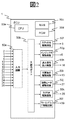
- FIG. 1 is a system block diagram showing a configuration of an ECU 1 according to an embodiment of the present invention.
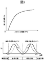
- FIG. 3 is a characteristic diagram of a throttle and a variable valve according to an embodiment of the present invention.
- FIG. 6 is an explanatory diagram of the characteristics of the injection command value in the command signal for the injector 6 output from the input / output port 50b and the characteristics of the injector 6 according to the embodiment of the present invention.
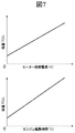
- FIG. 5 is an explanatory diagram of a characteristic of an oil temperature TOIL with respect to a heater supply current HC supplied to a heater 27 according to an embodiment of the present invention, and a characteristic of an oil temperature TOIL with respect to an engine start time TO.
- FIG. 10 is an explanatory diagram of the characteristics of an ion sensor according to a second embodiment of the present invention and the characteristics of a fuel property T90 with respect to an ion integral value.
- FIG. 6 is an explanatory diagram of signal processing of characteristics and acceleration sensor voltage of an acceleration sensor according to a second embodiment of the present invention.
- FIG. 6 is an explanatory diagram of signal processing results of pressure sensor characteristics and pressure sensor voltage according to the second embodiment of the present invention.
- FIG. 6 is an explanatory diagram of a signal processing result of fuel pressure sensor voltage according to a second embodiment of the present invention.
- FIG. 6 is an explanatory diagram of a signal processing result of a crank angle sensor voltage according to a second embodiment of the present invention.
- FIG. 6 is an explanatory diagram of a signal processing result of a voltage sensor according to a second embodiment of the present invention.
- FIG. 10 is an explanatory diagram of a control result for increasing the oil temperature according to the second embodiment of the present invention.
- 7 is a flowchart showing control contents in an ECU 1 according to a second embodiment of the present invention.
- FIG. 1 to FIG. 23 show a control device for controlling the temperature of oil that lubricates the inside of the engine of the present invention and controls the temperature of oil based on the detection result of the property of fuel supplied to the engine. It is explanatory drawing about the structure of the applied system.
- FIG. 1 is a system configuration diagram of an automobile engine system according to the present embodiment.
- the engine 100 is an automobile engine that performs spark ignition combustion.
- An airflow sensor 3 that measures the amount of intake air
- a throttle 5 that adjusts the intake pipe pressure
- an intake air temperature / humidity sensor 4 that measures the temperature and humidity of the intake air that is an aspect of the intake air temperature and humidity detector.
- Each of the tubes 9 is provided at an appropriate position.
- the airflow sensor 3 may be an intake air pressure sensor.
- the engine 100 is also provided with a fuel injection device (hereinafter referred to as an injector) 6 for injecting fuel into the combustion chamber 14 and an ignition plug 16 for supplying ignition energy, and intake air and exhaust flowing into the combustion chamber 14 are discharged.
- a variable valve 10 for adjusting the exhaust gas is provided at each appropriate position of the engine 100.
- a common rail 8 for supplying fuel by being connected to the injector 6, a fuel pump 7 for pumping fuel to the common rail 8, and a fuel pipe 32 for supplying fuel to the fuel pump 7 are disposed at appropriate positions of the engine 100. Is provided.
- a fuel pressure sensor that is an aspect of the fuel pressure detector and measures the fuel pressure is provided at an appropriate position on the common rail 8.
- the fuel pressure sensor may be a fuel temperature sensor.
- a fuel property sensor 22 for measuring the fuel property which is an aspect of the fuel property detector, is provided at an appropriate position on the common rail 8.
- the fuel property sensor 22 may be provided in any of the injector 6, the fuel pump 7, and the fuel pipe 32.
- the three-way catalyst 18 for purifying exhaust is one mode
- An air-fuel ratio sensor 20 for detecting the air-fuel ratio of the exhaust gas upstream of the three-way catalyst 18 and an exhaust gas recirculation pipe 29 connected to the intake pipe 9 are provided at appropriate positions of the exhaust pipe 17.
- the air-fuel ratio sensor 20 may be an oxygen concentration sensor.
- an EGR valve 28 for adjusting the exhaust gas recirculation amount is provided at an appropriate position of the exhaust gas recirculation pipe 29.
- the crankshaft 12 is provided with a crank angle sensor 13 for detecting the angle and rotational speed of the crankshaft 12 and the moving speed of the piston 11.
- a coolant temperature sensor 15 is provided at an appropriate position of the engine 100.
- an oil temperature sensor 25 that detects the temperature of oil that lubricates the inside of the engine is provided at an appropriate position of the engine 100.
- a hydraulic sensor 24 for detecting the pressure of oil that lubricates the inside of the engine is provided at an appropriate position of the engine 100.
- An acceleration sensor 21 that detects the acceleration of the engine is provided at an appropriate position of the engine 100.
- an ion sensor 23 for detecting the amount of ions generated due to combustion of fuel inside the engine is provided at an appropriate position of the engine 100.
- the ion sensor 23 may be a pressure sensor that detects the pressure inside the engine.
- the storage battery 31 is provided in the automobile engine system together with the engine 100, and the storage battery 31 supplies electric power of the automobile engine system via the electric wire 33.
- a voltage sensor 26 that is one mode of the voltage detector and measures the voltage of the storage battery 31 is provided at an appropriate position of the electric wire 33.
- the voltage sensor 26 may be a current sensor.
- the engine 100 is provided with a heater 27 for heating the oil that lubricates the engine 100.
- a warning lamp 30 is provided at an appropriate position of the automobile engine system.
- Signals obtained from the oil pressure sensor 24, the oil temperature sensor 25, and the voltage sensor 26 are sent to an engine control unit (hereinafter referred to as ECU 1).
- a signal obtained from the accelerator opening sensor 2 is sent to the ECU 1.
- the accelerator opening sensor 2 detects the amount of depression of the accelerator pedal, that is, the accelerator opening.
- the ECU 1 calculates the required torque based on the output signal of the accelerator opening sensor 2. That is, the accelerator opening sensor 2 is used as a required torque detection sensor that detects a required torque for the engine 100.
- the ECU 1 calculates the angle and rotational speed of the crankshaft 12 and the moving speed of the piston 11 based on the output signal of the crank angle sensor 13.
- the ECU 1 determines the opening degree of the throttle 5, the opening / closing timing of the variable valve 10, the opening degree of the EGR valve 28, the fuel pumping pressure of the fuel pump 7, the injector 6 based on the operating state of the engine 100 obtained from the outputs of the various sensors.
- the main operation amount of the engine 100 such as the injection pulse period, the ignition timing of the spark plug 16, the heater 27, the warning lamp 30, etc. is optimally calculated.
- the injection pulse period calculated by the ECU 1 is converted into an injector valve opening pulse signal and sent to the injector 6.
- a spark plug drive signal is sent to the spark plug 16 so as to be ignited at the ignition timing calculated by the ECU 1.
- the throttle opening calculated by the ECU 1 is sent to the throttle 5 as a throttle drive signal.
- the EGR valve opening calculated by the ECU 1 is sent to the EGR valve 28 as an EGR valve drive signal.
- the valve opening / closing timing calculated by the ECU 1 is sent to the variable valve 10 as a variable valve drive signal.
- Fuel is injected into the air flowing into the combustion chamber 14 from the intake pipe 9 via the intake valve to form an air-fuel mixture.
- the air-fuel mixture explodes by a spark generated from the spark plug 16 at a predetermined ignition timing, and the piston 11 is pushed down by the combustion pressure to become the driving force of the engine 100.
- the exhaust gas after the explosion is sent to the three-way catalyst 18 through the exhaust pipe 17, and the exhaust components are purified in the three-way catalyst 18 and then discharged.
- the engine 100 is mounted on an automobile, and information on the running state of the automobile is sent to the ECU 1.
- FIG. 2 is a system block diagram showing the configuration of the ECU 1 according to the embodiment of the present invention.
- Accelerator opening sensor 2, airflow sensor 3, intake air temperature sensor 4, fuel pressure sensor for common rail 8, crank angle sensor 13, cooling water temperature sensor 15, exhaust gas temperature sensor 19, air-fuel ratio sensor 20, acceleration sensor 21, fuel property sensor 22, the output signals of the ion sensor 23, the hydraulic pressure sensor 24, the oil temperature sensor 25, and the voltage sensor 26 are input to the input circuit 50a of the ECU 1.
- the input signal is not limited to these.
- the input signal of each sensor is sent to the input / output port in the input / output port 50b.
- the value sent to the input / output port 50b is stored in the RAM 50c and processed by the CPU 50e.
- a control program describing the contents of the arithmetic processing is written in advance in the ROM 50d.
- a value indicating the operation amount of each actuator calculated in accordance with the control program is stored in the RAM 50c, then sent to the output port of the input / output port 50b, and sent to each actuator via each drive circuit.
- a throttle drive circuit 50f there are a throttle drive circuit 50f, an injector drive circuit 50g, an ignition output circuit 50h, a variable valve drive circuit 50i, a heater drive circuit 50j, an EGR valve drive circuit 50k, and a warning lamp drive circuit 50l as drive circuits.
- Each circuit controls the throttle 5, the injector 6, the spark plug 16, the variable valve 10, the heater 27, the EGR valve 28, and the warning lamp 30.
- the drive circuit is provided in the ECU 1, but the present invention is not limited to this, and any of the drive circuits may be provided in the ECU 1.
- FIG. 3 is a characteristic diagram showing the characteristic of the throttle 5 and the characteristic of the variable valve according to the embodiment of the present invention.
- the vertical axis represents the intake air amount QA
- the horizontal axis represents the throttle opening TPO, which shows the characteristics of the intake air amount QA corresponding to the throttle opening TPO.
- the intake air amount QA can be increased.
- the vertical axis in the figure below shows the valve lift VL
- the horizontal axis shows the elapsed time
- the stroke of the engine 100 (expansion, exhaust, intake, compression) corresponding to the elapsed time is shown in the lower part of the figure.
- the exhaust valve can be opened / closed from the exhaust expansion stroke to the intake stroke
- the intake valve can be opened / closed from the exhaust stroke to the compression stroke.
- the timing at which the exhaust valve lift amount VL begins to increase is defined as the exhaust valve opening timing
- the timing at which the exhaust valve lift amount VL decreases and becomes zero is defined as the exhaust valve closing timing, so that the exhaust valve opening timing and the exhaust valve closing timing are delayed in time.
- a variable mechanism is provided, and the variable amount is defined as an exhaust valve retard angle VTCE.
- the timing at which the intake valve lift amount VL begins to increase is defined as the intake valve opening timing, and thereafter, the timing at which the intake valve lift amount VL decreases and becomes zero is defined as the intake valve closing timing, so that the intake valve opening timing and the intake valve closing timing are respectively accelerated on the time axis.
- a variable mechanism is provided, and the variable amount is defined as an intake valve advance angle VTCI.
- the intake valve and the exhaust valve are provided with a variable function for changing the profile of the valve lift amount VL continuously or stepwise, but the present invention is not limited to this, and the intake valve and the exhaust valve may have only the intake valve. Further, a mechanism for making the valve lift amount VL variable may be provided. By controlling the variable valve 10 and the throttle 5, the intake air amount QA in the combustion chamber 14 is adjusted.
- FIG. 4 is a characteristic diagram showing the characteristics of the injection command value in the command signal for the injector 6 output from the input / output port 50b and the characteristics of the injector 6 according to the embodiment of the present invention.
- the vertical axis represents the injection pulse voltage IP
- the horizontal axis represents the elapsed time.
- BDC indicates when the piston 11 is at bottom dead center
- TDC indicates when it is at top dead center
- the stroke (exhaust, intake, compression, expansion) of the engine 100 corresponding to the elapsed time is shown in the lower part of the figure.
- the engine control device of the present invention can command multiple injections.
- three injection pulses are shown in the intake stroke as a representative example.
- the first rising timing of the plurality of injection pulses in the intake stroke is the injection start timing IT_SP (n-2)
- the period from the rising timing to the subsequent falling timing is the first injection pulse period IP_SP (n-2 )
- the rising timing of the last stage of the plurality of injection pulses is the injection start timing IT_SP (n)
- the period from the rising timing to the subsequent falling timing is the last injection pulse period IP_SP (n).
- n is the number of injections.
- the vertical axis indicates the fuel injection amount QF
- the horizontal axis indicates the injection pulse period IP_SP.
- the fuel injection amount QF can be increased.
- the characteristics change as shown in the figure according to the fuel pressure FP of the common rail 8.
- FIG. 5 shows the characteristics of the ignition command value in the command signal for the spark plug 16 output from the input / output port 50b according to the embodiment of the present invention, and the EGR command value in the command signal for the EGR valve 28 output from the input / output port 50b.
- It is a characteristic view which shows an EGR flow rate characteristic.
- the vertical axis represents the ignition pulse voltage IGP
- the horizontal axis represents the elapsed time.
- BDC indicates when the piston 11 is at bottom dead center
- TDC indicates when it is at top dead center
- the stroke (intake, compression, expansion, exhaust) of the engine 100 corresponding to the elapsed time is shown in the lower part of the figure.
- the engine control device of the present invention can command multiple ignitions.
- two ignition pulses are shown as a representative example.
- the first rising timing in the compression stroke of the plurality of ignition pulses is the ignition start timing IGT (m-1)
- the last rising timing of the plurality of ignition pulses is the ignition start timing IGT (m).
- m is the number of ignitions.
- the vertical axis in the figure below shows the EGR flow rate QE
- the horizontal axis shows the EGR valve opening EPO of the EGR valve 28.
- the EGR flow rate QE can be increased as the EGR valve opening EPO increases.
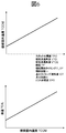
- FIG. 6 is a characteristic diagram showing the characteristics of the temperature in the combustion chamber with respect to the command value and the characteristics of the oil temperature with respect to the temperature in the combustion chamber according to the embodiment of the present invention.
- the vertical axis represents the combustion chamber temperature TCOM
- the horizontal axis represents the above-described command values.
- Each command value that is, throttle opening TPO, intake valve advance angle VTCI, exhaust valve retard angle VTCE, injection start timing IT_SP, fuel pressure FP, injection count n, ignition timing advance angle IGT, ignition count m, EGR valve opening EPO
- the combustion chamber temperature TCOM increases as it increases. The factors that change the combustion chamber temperature TCOM by each command are shown below.
- the intake valve advance angle VTCI increases, the intake valve closing timing approaches BDC as shown in the characteristic diagram of the variable valve described above, and the actual compression ratio increases.
- the exhaust valve retard angle VTCE increases, the exhaust valve opening timing approaches BDC as shown in the characteristic diagram of the variable valve described above, and the actual expansion ratio increases.
- the injection start timing IT_SP increases with reference to BDC, that is, by approaching the TDC in the intake stroke, the time with the TDC in the compression stroke can be increased. As a result, the vaporization of the fuel proceeds and the mixing with the intake air is improved.
- the fuel injected from the injector 6 is atomized and is better mixed with the intake air, thereby reducing unburned components.
- the number of injections n is increased, the penetration force of the fuel injected from the injector 6 is reduced and the extension distance is shortened. As a result, the fuel adhering to the wall surface of the combustion chamber 14 is reduced.
- the increase in the ignition timing advance angle IGT is caused by advancing the timing for igniting the air-fuel mixture in the combustion chamber 14 and increasing the pressure in the combustion chamber 14.
- An increase in the number of times of ignition m is equivalent to an increase in the ignition energy shared by the air-fuel mixture in the combustion chamber 14, resulting in an increase in the volume of flame kernels at the initial stage of combustion generated by ignition and the faster combustion. by.
- the EGR valve opening EPO increases, the EGR flow rate QE decreases as shown in the characteristic diagram of the EGR valve 28 described above. As a result, the EGR flow rate flowing into the combustion chamber 14 decreases, and the specific heat of the air-fuel mixture decreases.
- the vertical axis in the figure below shows the oil temperature TOIL, and the horizontal axis shows the combustion chamber temperature TCOM.
- the oil temperature TOIL increases. This is because the temperature of the engine 100 increases as the temperature in the combustion chamber increases, and the temperature of the oil that lubricates the engine 100 also increases.
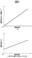
- FIG. 7 is a characteristic diagram showing the characteristic of the oil temperature TOIL with respect to the heater supply current HC supplied to the heater 27 and the characteristic of the oil temperature TOIL with respect to the engine start time TO according to the embodiment of the present invention.
- the vertical axis in the upper diagram indicates the oil temperature TOIL, and the horizontal axis indicates the heater supply current HC.
- the heater supply current HC increases, the oil temperature TOIL increases.
- the vertical axis in the figure below shows the oil temperature TOIL, and the horizontal axis shows the engine start time TO.
- the oil temperature TOIL increases. This is because the engine 100 is heated due to a longer time during which the engine 100 is operated.
- FIG. 8 is a characteristic diagram showing the characteristics of the fuel property sensor 22 according to the embodiment of the present invention and the characteristics of the octane number and the deterioration level with respect to the fuel property T90.
- T90 means 90% distillation temperature of fuel.
- the vertical axis of the upper graph indicates the fuel property sensor voltage VF, and the horizontal axis indicates the fuel property T90. When the fuel property T90 increases, the fuel property sensor voltage VF increases.
- the vertical axis in the figure below shows the fuel property T90, and the horizontal axis shows the fuel property 1 / octane number NO and the fuel property deterioration level LDE.
- the fuel property T90 increases. This is because the fuel property 1 / octane number NO increases, that is, the heavy components of the fuel increase and the auto-ignition temperature decreases. Further, the fuel property deterioration level LDE increases, that is, the light components of the fuel decrease and the fuel deteriorates and deteriorates.
- the fuel property T90, 1 / octane number NO, and deterioration level LDE are calculated.
- the present invention is not limited to this, and vaporization characteristics, combustion characteristics, and the like regarding the fuel composition may be used.
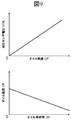
- FIG. 9 is a characteristic diagram showing the characteristics of the hydraulic sensor 24 according to the embodiment of the present invention and the characteristics of the oil dilution ratio DR with respect to the oil viscosity CP.
- the vertical axis represents the hydraulic pressure sensor voltage VOIL
- the horizontal axis represents the oil viscosity CP.
- the vertical axis in the figure below shows the oil viscosity CP
- the horizontal axis shows the oil dilution rate DR.
- the oil viscosity CP decreases.
- the oil dilution rate DR is calculated using the oil viscosity CP and the hydraulic pressure sensor VOIL, but not limited thereto, the fuel mass diluted in the oil, the composition of the oil, the oxygen concentration in the crankcase, An accumulated fuel injection amount after the engine is started may be used.
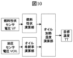
- FIG. 10 is a logic diagram showing the calculation logic of the oil heating temperature according to the embodiment of the present invention.
- the fuel property sensor voltage VF is input to a fuel property calculation unit, and calculates one or more of the fuel property T90, 1 / octane number NO, and deterioration level LDE based on the characteristic diagram of FIG.
- the calculation result is input to the oil heating temperature calculation unit.
- the oil pressure sensor voltage VOIL is input to the oil dilution rate calculation unit, and calculates the oil dilution rate DR based on the characteristic diagram of FIG.
- the calculation result is also input to the oil heating temperature calculation unit.
- the oil heating temperature calculation unit calculates the target temperature TT using the calculation result.
- a predetermined value for example, a mass ratio of 6% or higher
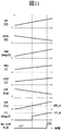
- FIG. 11 is a characteristic diagram of the oil heating temperature calculation logic showing an example of calculation results of the oil heating temperature calculation logic according to the embodiment of the present invention.
- an input is given in which the fuel property sensor voltage VF increases with time and the hydraulic pressure sensor voltage decreases with time.
- the fuel property calculator 90 increases the fuel property T90.
- the fuel property 1 / octane number NO increases, and the fuel property deterioration level LDE also increases.
- the hydraulic pressure sensor voltage VOIL decreases, the oil viscosity CP decreases and the oil dilution rate DR increases.
- the target temperature TT is output when the oil dilution rate DR exceeds the oil dilution rate limit value DR_K as compared with the oil dilution rate limit value DR_K previously written in the control device of the engine of the present invention.
- the target temperature TT is output so as to increase as the fuel property T90 increases.
- the warning FLG is turned ON when the target temperature TT exceeds the target temperature limit value TT_K as compared with the target temperature limit value TT_K written in advance in the engine control device of the present invention.
- the target temperature limit value TT_K is 130 degrees or less.
- the present invention is not limited to this.
- the fuel property sensor voltage VF is a constant value, and the hydraulic sensor voltage VOIL This logic can be applied even when various input values such as a constant value exist.
- FIG. 12 is an oil heating control calculation logic diagram showing the logic of the oil heating control calculation unit according to the embodiment of the present invention.
- the target temperature TT is input to the oil heating control calculation unit.
- the oil heating control calculation unit calculates the combustion chamber temperature TCOM, the heater supply current HC, and the engine start time TO shown in FIGS. Also, the combustion chamber temperature TCOM is based on FIG. 6, throttle opening TPO, intake valve advance angle VTCI, exhaust valve retard angle VTCE, fuel pressure FP, injection timing IT_SP, injection number n, ignition timing advance angle IGT, ignition number m, It is converted into EGR valve opening EPO.
- the calculation results are output as heater supply HC, throttle opening TPO, intake valve advance angle VTCI, exhaust valve retard angle VTCE, fuel pressure FP, number of injections n, ignition timing advance angle IGT, number of ignitions m, EGR valve opening EPO
- each control calculation result is output here, not only that but one or more of the calculation results may be calculated.
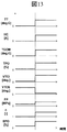
- FIG. 13 is a characteristic diagram of the oil heating control calculation unit showing an example of calculation results of the oil heating control calculation unit according to the embodiment of the present invention.
- an example of calculation results when the target temperature TT is output based on the oil dilution rate DR, the oil dilution rate limit value DR_K, and the fuel property T90 is shown.
- the target temperature TT is calculated based on the oil dilution rate DR, the oil dilution rate limit value DR_K, and the fuel property T90.
- the oil heating control calculation unit performs the above calculation.
- FIG. 14 is an example of a control result for increasing the oil temperature, that is, the oil temperature according to the embodiment of the present invention.
- the oil dilution rate DR exceeds the oil dilution rate limit value DR_K
- the target temperature TT is output based on the fuel property T90, and the heater supply current HC and the combustion chamber temperature TCOM are increased.
- the oil temperature TOIL increases, and the oil dilution ratio DR decreases accordingly. This is because the fuel diluted in oil vaporizes as the oil temperature rises.
- the target temperature TT stops calculating, and the heater supply current HC and the combustion chamber temperature TCOM calculation stop.
- the present invention controls the oil dilution rate DR.
- the fuel property T90 indicated by the dotted line is lower than the fuel property T90 indicated by the solid line, and when the fuel property T90 is lower than the solid fuel property T90 as indicated by the dotted line, the target The temperature TT is calculated low, the heater supply current HC is low, and the combustion chamber temperature TCOM is also calculated low.
- the oil temperature TOIL is controlled to be low. This is because when a fuel having a low fuel property T90 is used, it can be vaporized even if the oil temperature TOIL is set low. It is possible to achieve both reduction of the oil dilution rate DR and minimization of energy consumption such as the heater supply current HC by the heating control according to the fuel property T90.
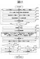
- FIG. 15 is a flowchart showing control contents in the ECU 1 according to the embodiment of the present invention.
- the control contents shown in FIG. 15 are repeatedly executed by the ECU 1 at a predetermined cycle.
- step S101 the accelerator opening APO, the engine speed NE, the vehicle speed VX, the values written in the ROM in ECU1, and the like are read.
- the required torque for engine 100 is calculated based on the output signal of accelerator opening sensor 2.
- step S102 the throttle 5, the variable valve 10, the injector 6 and the like are controlled so as to realize an appropriate intake air amount QA based on the result of step S101.
- the ECU 1 reads the fuel property sensor voltage VF and the hydraulic pressure sensor voltage VOIL in step S103.
- ECU 1 performs fuel property calculation and oil dilution rate calculation in step S104.
- ECU1 performs oil heating temperature calculation in step S105.
- step S106 it is determined whether the oil dilution rate DR is larger than the oil dilution rate limit value DR_K. If YES, the process proceeds to step 107, and if NO, the process returns to step S101.
- step S107 the target temperature TT is read.
- step S108 an oil heating control calculation is performed.
- step S109 heater supply current HC, throttle opening TPO, intake valve advance angle VTCI, exhaust valve retard angle VTCE, fuel pressure FP, injection start timing IT_SP, injection number n, ignition timing advance angle IGT, ignition number m, EGR Reads valve opening EPO and engine start time TO.
- step S110 oil heating control is activated based on the command value read in step S109 to control each device.
- step S111 the oil pressure sensor voltage VOIL and the oil temperature sensor voltage TOIL are read.
- step S112 it is determined whether the target temperature TT is higher than the target temperature limit value TT_K. If YES, the process proceeds to step S113, and if NO, the process proceeds to step S115. In step S113, the warning FLG is turned ON.
- step S114 the oil heating control is stopped.
- step S115 it is determined whether the oil dilution rate DR is equal to or less than the oil dilution rate limit value DR_K. If YES, the process proceeds to step S116. If NO, the process proceeds to step S107, and oil heating control is repeatedly performed. In step S116, the oil heating control is stopped. The above flow is executed by the ECU 1 at a predetermined cycle.
- the target temperature of the engine oil is determined based on the detected fuel property.
- the value can be set appropriately. As a result, it is possible to suppress the occurrence of excessive heating or insufficient heating of the oil, and it is possible to contribute to both regeneration of fuel consumption and lubrication performance.
- FIG. 16 17, 18, 19, 20, 21, and 22.
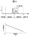
- FIG. 16 is a characteristic diagram showing the characteristics of the ion sensor 23 according to the second embodiment of the present invention and the characteristics of the fuel property T90 with respect to the ion integral value.
- the vertical axis represents the ion sensor voltage VI
- the horizontal axis represents time.
- the ion sensor voltage VI is applied from the compression stroke to the expansion stroke, and an amplitude signal as shown in the figure is output.
- the output shown here is an example, and the output changes according to the operating state of engine 100.
- a value obtained by integrating the ion sensor voltage VI from the compression stroke to the expansion stroke is defined as an ion integral value II.
- the ECU 1 calculates the ion integral value II.
- the vertical axis in the figure below shows the ion integral value II
- the horizontal axis shows the fuel property T90.
- the ion integral value II decreases as the fuel property T90 increases. This is because when the fuel property T90 increases, the 1 / octane number increases, so that the ignition timing retardation for avoiding knocking is performed, so that the amount of ions in the combustion chamber 14 decreases, resulting in ion integration. The reason is that the value II decreases.
- FIG. 17 is a characteristic diagram showing an example of the signal processing of the characteristics of the acceleration sensor 21 and the acceleration sensor voltage according to the second embodiment of the present invention.
- the vertical axis represents the acceleration sensor voltage VV
- the horizontal axis represents time.
- the acceleration sensor voltage VV outputs an amplitude signal as shown in the figure from the compression stroke to the expansion stroke.
- the output shown here is an example, and the output changes according to the operating state of engine 100.
- a middle example shows a calculation example of frequency analysis of the acceleration sensor voltage VV from the compression stroke to the expansion stroke.
- the vertical axis in the middle diagram shows the power spectrum PSV
- the horizontal axis shows the frequency.
- the signal intensity at each frequency that is, the power spectrum PSV can be calculated.
- the power spectrum PSV is integrated at an arbitrary frequency and defined as a power spectrum integration value VI.
- the vertical axis in the figure below shows the power spectrum integrated value VI
- the horizontal axis shows the fuel property T90.
- the power spectrum integral value VI decreases. This is because when the fuel property T90 is increased and the 1 / octane number is increased, the ignition timing retardation for avoiding knocking is performed, so that the vibration of the engine 100 is reduced, and as a result, the power spectrum integrated value VI This is due to a decrease in
- FIG. 18 is a characteristic diagram showing an example of the pressure sensor characteristic and the pressure sensor voltage signal processing result according to the second embodiment of the present invention.
- the pressure sensor is provided in the combustion chamber 14.
- the vertical axis indicates the pressure sensor voltage VP
- the horizontal axis indicates time.
- the pressure sensor voltage VP outputs an amplitude signal as shown in the figure from the compression stroke to the expansion stroke.
- the output shown here is an example, and the output changes according to the operating state of engine 100.
- a calculation example in which the frequency analysis of the pressure sensor voltage VP is performed from the compression stroke to the expansion stroke is shown in the middle diagram.
- the vertical axis in the middle diagram shows the power spectrum PSP
- the horizontal axis shows the frequency.
- the signal intensity at each frequency that is, the power spectrum PSP can be calculated.
- the power spectrum PSP is integrated at an arbitrary frequency and defined as a power spectrum integration value PI.
- the vertical axis in the figure below shows the power spectrum integral value PI
- the horizontal axis shows the fuel property T90.
- the power spectrum integral value PI decreases. This is because the fuel property T90 is increased and the 1 / octane number is increased, so that the ignition timing retardation for avoiding knocking is performed, so that the pressure in the combustion chamber 14 is reduced, and as a result, the power spectrum integrated value This is due to a decrease in PI.
- FIG. 19 is a characteristic diagram showing an example of the signal processing result of the fuel pressure sensor voltage according to the second embodiment of the present invention.
- the fuel pressure sensor is provided on the common rail 8.
- the vertical axis of the upper diagram shows the fuel pressure sensor voltage VFP, and the horizontal axis shows time.
- the pressure sensor voltage VFP outputs a voltage signal as shown in the figure in each cylinder.
- the output shown here is an example, and the output changes according to the operating state of engine 100.
- the difference between the fuel pressure sensor voltage VFP and the target fuel pressure is defined as ⁇ VFP and is shown in the middle diagram.
- the vertical axis represents the fuel pressure difference ⁇ VFP, and the horizontal axis represents time.
- the fuel pressure difference ⁇ VFP indicates a value that increases or decreases around zero.
- the time average of the fuel pressure difference ⁇ VFP is defined as the fuel pressure difference average value ⁇ VFP_A.
- the vertical axis in the figure below indicates the fuel pressure difference average value ⁇ VFP_A, and the horizontal axis indicates the fuel property T90.
- the fuel pressure difference average value ⁇ VFP_A increases as the fuel property T90 increases. This is because the light component is vaporized as the fuel property T90 increases, and as a result, the fuel pressure tends to increase with respect to the target fuel pressure.
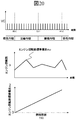
- FIG. 20 is a characteristic diagram showing an example of the signal processing result of the crank angle sensor voltage according to the second embodiment of the present invention.
- the crank angle sensor 13 is provided at a position close to the crankshaft 12.
- the vertical axis represents the crank angle sensor voltage VC
- the horizontal axis represents time.
- the crank angle sensor voltage VC outputs a pulse signal as shown in the drawing in the intake stroke, the compression stroke, the expansion stroke, and the exhaust stroke.
- the output shown here is an example, and the output varies depending on the structure of a gear or the like fastened to the crankshaft 12. If the engine speed ⁇ is calculated using the crank angle sensor voltage VC and time, the result shown in the middle diagram is obtained.
- the vertical axis represents the engine speed ⁇
- the horizontal axis represents time.
- the engine speed ⁇ changes sequentially as shown in the figure.
- the standard deviation of the engine speed ⁇ is defined as the engine speed standard change ⁇ and is calculated.
- the engine speed standard deviation ⁇ indicates the fluctuation of the engine speed.
- the present invention calculates the standard deviation, but is not limited thereto, and various deviations, average values, and the like may be used.
- the vertical axis of the lower graph indicates the engine speed standard deviation ⁇
- the horizontal axis indicates the fuel property T90. As the fuel property T90 increases, the engine speed standard deviation ⁇ increases. This is because heavy components remain due to an increase in the fuel property T90, which deteriorates the vaporization of the fuel and the mixture of the air-fuel mixture. As a result, the fluctuation of the engine speed is likely to increase.
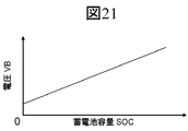
- FIG. 21 is a characteristic diagram showing an example of a signal processing result of the voltage sensor according to the second embodiment of the present invention.
- the voltage sensor is provided at an appropriate position of the electric wire 33.
- the vertical axis indicates the voltage VB
- the horizontal axis indicates the storage battery capacity SOC.
- the voltage VB increases as the storage battery capacity SOC increases.
- the same relationship with the parameter relating to the charge energy remaining in the storage battery 31 may be used.
- FIG. 22 is an example of a control result for increasing the oil temperature, that is, the oil temperature according to the second embodiment of the present invention.
- the oil dilution rate DR exceeds the oil dilution rate limit value DR_K and the storage battery capacity SOC is larger than the storage battery capacity limit value SOC_K, which is an arbitrary value
- the target temperature TT is output based on the fuel property T90, and the heater is supplied Current HC and combustion chamber temperature TCOM are increased.
- the oil temperature TOIL rises, and along with this, the increasing tendency of the oil dilution ratio DR decreases. This is because the fuel diluted in oil vaporizes as the oil temperature rises.
- the target temperature TT stops outputting even when the oil dilution rate DR is larger than the oil dilution rate limit value.
- the target temperature TT is output, and the heater supply current HC and the combustion chamber temperature TCOM are output based on the fuel property T90.
- the oil temperature rises once, then stagnates and rises again. That is, when the oil dilution rate DR is larger than the oil dilution rate limit value DR_K and the storage battery capacity SOC is larger than the storage battery capacity limit value, the heating control is performed based on the fuel property T90. Further, the target temperature TT changes based on the fuel property T90.
- the target temperature TT stops calculating, and the heater supply current HC and the combustion chamber temperature TCOM calculation stop. As a result, the oil temperature TOIL decreases.
- the present invention controls the oil dilution rate DR.
- the fuel property T90 indicated by the dotted line is lower than the fuel property T90 indicated by the solid line, and when the fuel property T90 is lower than the solid fuel property T90 as indicated by the dotted line, the target The temperature TT is calculated low, the heater supply current HC is low, and the combustion chamber temperature TCOM is also calculated low.
- the oil temperature TOIL is controlled to be low. This is because when a fuel having a low fuel property T90 is used, it can be vaporized even if the oil temperature TOIL is set low. It is possible to achieve both reduction of the oil dilution rate DR and minimization of energy consumption such as the heater supply current HC by the heating control according to the fuel property T90.
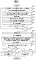
- FIG. 23 is a flowchart showing control contents in the ECU 1 according to the second embodiment of the present invention.
- the control contents shown in FIG. 23 are repeatedly executed by the ECU 1 at a predetermined cycle.
- the accelerator opening APO, engine speed NE, vehicle speed VX, values written in ROM in ECU1, and the like are read.
- the required torque for engine 100 is calculated based on the output signal of accelerator opening sensor 2.
- step S202 the throttle 5, the variable valve 10, the injector 6 and the like are controlled so as to achieve an appropriate intake air amount QA based on the result of step S201.
- ECU 1 reads the ion sensor voltage VI, acceleration sensor voltage VV, pressure sensor voltage VP, fuel pressure sensor voltage VFP, and crank angle sensor voltage VC in step S203.
- the ECU 1 performs fuel property calculation in step S205.
- ECU1 reads the hydraulic pressure sensor voltage VOIL and voltage VB in step S205.
- step S206 the oil dilution rate and the storage battery capacity are calculated.
- step S207 oil heating temperature calculation is performed.
- step S208 it is determined whether the oil dilution rate DR is larger than the oil dilution rate limit value DR_K. If YES, the process proceeds to step S209, and if NO, the process proceeds to step S201.
- step S209 it is determined whether the storage battery capacity SOC is larger than the storage battery capacity limit value SOC_K. If YES, the process proceeds to step S210. If NO, the process proceeds to step S201. Next, in step S210, the target temperature TT is read.
- step S211 an oil heating control value is calculated.
- step S212 heater supply current HC, throttle opening TPO, intake valve advance angle VTCI, exhaust valve retard angle VTCE, fuel pressure FP, injection timing IT_SP, injection number n, ignition timing advance angle IGT, ignition number m, EGR valve Reads the opening EPO and engine start time TO.
- step S213 oil heating control is started based on the command value read in step S212, and each device is controlled.
- step S214 the oil pressure sensor voltage VOIL and the oil temperature sensor voltage TOIL are read.
- step S215 it is determined whether the target temperature TT is higher than the target temperature limit value TT_K. If YES, the process proceeds to step S216, and if NO, the process proceeds to step S218. In step S216, the warning FLG is turned ON.
- step S217 the oil heating control is stopped.
- step S218 it is determined whether the oil dilution rate DR is equal to or less than the oil dilution rate limit value DR_K. If YES, the process proceeds to step S219. If NO, the process proceeds to step S210, and oil heating control is repeatedly performed. In step S219, the oil heating control is stopped. The above flow is executed by the ECU 1 at a predetermined cycle.
- the fuel property is detected using means other than the fuel property sensor, and the target value of the engine oil temperature can be appropriately set based on the detected fuel property.
- the target value of the engine oil temperature can be appropriately set based on the detected fuel property.
Landscapes
- Engineering & Computer Science (AREA)
- Mechanical Engineering (AREA)
- General Engineering & Computer Science (AREA)
- Chemical & Material Sciences (AREA)
- Combustion & Propulsion (AREA)
- Combined Controls Of Internal Combustion Engines (AREA)
- Electrical Control Of Air Or Fuel Supplied To Internal-Combustion Engine (AREA)
- Output Control And Ontrol Of Special Type Engine (AREA)
- Lubrication Of Internal Combustion Engines (AREA)
Abstract
本発明によれば、ガソリンを燃料とするエンジンにおいて、ガソリンが混合組成であるが故に単一の沸点を有さないこと、また燃料性状が変化する、例えば劣化による気化特性の変化が発生した場合でも、エンジンオイルの温度の目標値を適切に設定する。すなわち、使用する燃料の気化特性が難気化である条件において、オイルの温度を高温側へ変更し、また使用する燃料の気化特性が容易気化である条件において、オイルの温度を低温側へ変更することで、余剰加熱あるいは加熱不足の発生を抑制するエンジンの制御装置を提供する。 エンジン内部を潤滑するオイルの温度を制御するオイル温度制御手段を有し、前記エンジンに燃料を供給する燃料供給装置を有し、前記燃料の性状の検出手段を有するエンジン制御装置において、前記燃料の性状の検出手段の信号に基づいて、前記オイルの温度を制御する。
Description
本発明は車両等に搭載されるエンジンの制御装置に関する。
現在の自動車は、環境保全の観点から燃費低減を強く要求されている。前記燃費低減の手段として、筒内直噴燃料供給装置を備えるダウンサイジングエンジンの開発が進められている。前記筒内直噴燃料供給装置は燃料噴射弁(以下、インジェクタと呼ぶ)を用いて燃焼室内に燃料噴射を直接実施するものであり、燃焼室内を冷却することで異常燃焼の抑制効果が得られる。この異常燃焼の抑制効果により、エンジンのダウンサイジングが可能となり燃費低減の効果が得られる。上記ダウンサイジングエンジンでは、燃焼室容積が小さくなるため上記インジェクタと壁面との距離が短くなり、噴射した燃料がピストン冠面やシリンダ等の壁面付着が発生し易くなる。付着した燃料は、ピストンリングにかき落とされクランクケース内へと導かれ、エンジンオイルに溶解する。その結果、燃料によってエンジンオイルが希釈(以下、オイル希釈と呼ぶ)され、潤滑性能が低下する課題がある。
そのため、例えば特許文献1には、内燃機関のクランクケース内に、潤滑油加熱室を画成するとともに該加熱室内に、クランクケース下部の潤滑油溜内の潤滑油を圧送供給するためのオイルポンプを設け、前記潤滑油加熱室の隔壁に、該室内の貯留潤滑油を溢流させて前記潤滑油溜内に還流させる流出口を開口し、また前記潤滑油加熱室内に、該室内上部の空隙部に連通するブリーザ口を開口し、このブリーザ口をクランクケースの上部に形成したブリーザ室に連通し、さらに前記潤滑油加熱室内には潤滑油溜内の油温が所定温度以下で作動し、該室内の貯留潤滑油を加熱するヒータを設けてなる、内燃機関における潤滑油の加熱装置が開示されている。
また、例えば特許文献2には、エンジンオイルの希釈率に関するパラメータの値を検出する検出手段と、該エンジンオイルを加熱する加熱装置と、該検出手段により検出されたパラメータの値と所定の閾値とを比較して、この結果に基づいて該加熱装置を作動させる制御手段とをそなえていることを特徴とするエンジンオイルの希釈防止装置が開示されている。
また、例えば特許文献3には、エンジンに燃料を供給するインジェクタと、前記インジェクタから噴射された燃料によって希釈されたエンジンオイルの再生時期を検出する再生時期検出手段と、エンジンオイルの再生時期であるときに、燃料で希釈されたエンジンオイルを昇温してエンジンオイルを再生するオイル昇温手段と、を有し、該オイル昇温手段はエンジン冷却水の水温を昇温することを特徴とする希釈オイル再生装置が開示されている。
また、例えば特許文献4には、アルコール燃料を使用可能なエンジンを備える車両に搭載され、前記エンジンの作動中に前記エンジンに吸入される空気量を積算して積算吸気量を算出する吸気量積算手段と、前記エンジンのエンジンオイルのオイル温度を検出する温度検出手段と、前記算出された積算吸気量が積算吸気量閾値より大きく、且つ前記検出されたオイル温度が第1温度閾値より低いことを条件に、前記オイル温度を上昇させるオイル加熱モードへ移行するように前記車両を制御する制御手段と、を備えることを特徴とするオイル希釈抑制装置が開示されている。該特許は、オイル加熱モード時の加熱温度の目標値をアルコール燃料の沸点を考慮して設定することが開示されている。
特許文献1記載の技術では、オイル希釈が発生し易い低油温状態において加熱を実施するため、オイル希釈が発生していなくとも加熱するため余剰加熱が発生する。
また、特許文献2記載の技術では、オイル希釈が所定以上に達した時にエンジンオイルの加熱制御を実施するためオイル希釈未発生時の余剰加熱を抑制できると考えられるが、加熱制御の温度設定に関する指標が無いためオイル希釈発生時の余剰加熱と加熱不足による潤滑性能再生不足が発生する。
また、特許文献3記載の技術は、オイルの加熱を冷却水の加熱を用いて実施するものであり、オイル温度を直接加熱する装置を備えずにしてオイル昇温が実施できると考えられるが、加熱制御の温度設定に関する指標が無いためオイル希釈発生時の余剰加熱と加熱不足による潤滑性能再生不足が発生する。
これらの従来技術では、オイル希釈したオイルの潤滑性を再生する手段としてオイル温度を昇温することで燃料を気化させることが開示されているが、エンジンオイルの温度の目標値を正確に示していないため、余剰加熱による燃費の悪化、あるいは加熱不足による潤滑性能の再生不足が発生する課題がある。
ここで、特許文献4記載の技術では、アルコール燃料の沸点をエンジンオイルの温度の目標値とするため、アルコール燃料においては過不足無くオイル加熱が可能となり燃費と潤滑性能の再生が両立できると考えられるが、ガソリン、混合燃料、気液混合燃料などにおいては、混合物性であるため沸点の設定は困難であり、余剰加熱による燃費の悪化、あるいは加熱不足による潤滑性能の再生不足が発生する課題がある。
このように、従来技術では、ガソリン、混合燃料、気液混合燃料などを燃料とするエンジンにおいては、混合組成であるが故に単一の沸点を有さないこと、また燃料性状が変化する、例えば劣化による気化特性の変化が発生した場合、沸点をエンジンオイルの温度の目標値とした時、余剰加熱あるいは加熱不足が発生することは必然であり、その結果、燃費の悪化あるいは潤滑性能の再生不足が発生する課題がある。
本発明は上記課題を鑑みてなされたものであり、本発明の目的は、燃料性状に基づいてオイル加熱手段のオイルの温度を設定することにより、燃費と潤滑性能再生を両立するエンジンの制御装置を提供することにある。
かかる目的を達成すべく本発明の制御装置は、エンジン内部を潤滑するオイルの温度を制御するエンジン制御装置において、前記エンジンに供給する燃料の性状の検出結果に基づいて、前記オイルの温度を制御することを特徴とする。
本発明によれば、ガソリン、混合燃料、気液混合燃料などを燃料とするエンジンにおいて、混合物性であるが故に単一の沸点を有さないこと、また燃料性状が変化する、例えば劣化による気化特性の変化が発生した場合でも、エンジンオイルの温度の目標値を適切に設定する。すなわち、使用する燃料の気化特性が難気化である条件において、オイルの温度を高温側へ変更し、また使用する燃料の気化特性が容易気化である条件において、オイルの温度を低温側へ変更することで、余剰加熱あるいは加熱不足の発生を抑制することを可能とし、燃費と潤滑性能の再生を両立に貢献することができる。
以下図1から図23を用いて本発明のエンジンの制御装置の構成および動作について説明する。
図1から図23は、本発明の、エンジン内部を潤滑するオイルの温度を制御し、エンジンに供給する燃料の性状の検出結果に基づいて、オイルの温度を制御する制御装置を自動車用エンジンに適用させたシステムの構成についての説明図である。
図1は本実施形態による自動車用エンジンシステムのシステム構成図である。エンジン100は、火花点火式燃焼を実施する自動車用エンジンである。吸入空気量を計測するエアフロセンサ3と、吸気管圧力を調整するスロットル5と、吸入空気温度および湿度検出器の一態様であって吸入空気の温度および湿度を計測する吸気温湿度センサ4が吸気管9の各々の適宜位置に備えられている。
エアフロセンサ3は吸入空気圧力センサとしてもよい。またエンジン100には燃焼室14の中に燃料を噴射する燃料噴射装置(以下、インジェクタと呼ぶ)6と、点火エネルギを供給する点火プラグ16が備えられ、燃焼室14に流入する吸入空気と排出する排気を調整する可変動弁10がエンジン100の各々の適宜位置に備えられている。上記インジェクタ6と連結することで燃料を供給するコモンレール8と該コモンレール8に燃料を圧送するための燃料ポンプ7と該燃料ポンプ7に燃料を供給する燃料配管32がエンジン100の各々の適宜位置に備えられている。
また燃料圧力検出器の一態様であって燃料の圧力を計測する燃料圧力センサがコモンレール8の適宜位置に備えられている。ここで燃料圧力センサは燃料温度センサであってもよい。
また燃料性状検出器の一態様であって燃料性状を計測する燃料性状センサ22がコモンレール8の適宜位置に備えられている。また該燃料性状センサ22はインジェクタ6、燃料ポンプ7、燃料配管32のいずれに備えられていてもよい。
さらに排気を浄化する三元触媒18と、排気温検出器が一態様であって三元触媒18の上流側にて排気の温度を計測する排気温センサ19と、空燃比検出器の一態様であって三元触媒18の上流側にて排気の空燃比を検出する空燃比センサ20と前記吸気管9へ連結される排気還流管29とが排気管17の各々の適宜位置に備えられている。空燃比センサ20は酸素濃度センサとしてもよい。
また排気還流量を調整するEGR弁28が排気還流管29の適宜位置に備えられている。またクランクシャフト12には該クランクシャフト12の角度および回転速度およびピストン11の移動速度を検出するためのクランク角センサ13が備えられている。また冷却水温センサ15がエンジン100の適宜位置に備えられている。
またエンジン内部を潤滑するオイルの温度を検出する油温センサ25がエンジン100の適宜位置に備えられている。またエンジン内部を潤滑するオイルの圧力を検出する油圧センサ24がエンジン100の適宜位置に備えられている。またエンジンの加速度を検出する加速度センサ21がエンジン100の適宜位置に備えられている。
またエンジン内部の燃料の燃焼に起因して発生するイオン量を検出するイオンセンサ23がエンジン100の適宜位置に備えられている。また該イオンセンサ23はエンジン内部の圧力を検出する圧力センサであってもよい。
また蓄電池31がエンジン100と共に当該自動車用エンジンシステムに備えられ、蓄電池31は当該自動車用エンジンシステムの電力を電線33を介して供給している。また電圧検出器の一態様であって蓄電池31の電圧を計測する電圧センサ26が電線33の適宜位置に備えられている。ここで電圧センサ26は電流センサであってもよい。
またエンジン100を潤滑するオイルを加熱するための加熱ヒータ27がエンジン100に備えられている。またウォーニングランプ30が当該自動車用エンジンシステムの適宜位置に備えられている。
エアフロセンサ3と吸気温センサ4とコモンレール8に備えられる燃料圧力センサとクランク角センサ13と冷却水温センサ15と排気温センサ19と空燃比センサ20と加速度センサ21と燃料性状センサ22とイオンセンサ23と油圧センサ24と油温センサ25と電圧センサ26とから得られる信号は、エンジンコントロールユニット(以下、ECU1)に送られる。アクセル開度センサ2から得られる信号はECU1に送られる。アクセル開度センサ2はアクセルペダルの踏み込み量、すなわちアクセル開度を検出する。ECU1はアクセル開度センサ2の出力信号に基づいて要求トルクを演算する。すなわちアクセル開度センサ2はエンジン100への要求トルクを検出する要求トルク検出センサとして用いられる。ECU1はクランク角センサ13の出力信号に基づいてクランクシャフト12の角度および回転速度およびピストン11の移動速度を演算する。
ECU1は前記各種センサの出力から得られるエンジン100の運転状態に基づいてスロットル5の開度、可変動弁10の弁開閉タイミング、EGR弁28の開度、燃料ポンプ7の燃料圧送圧力、インジェクタ6の噴射パルス期間、点火プラグ16の点火タイミング、加熱ヒータ27、ウォーニングランプ30などのエンジン100の主要な作動量を最適に演算する。ECU1で演算された噴射パルス期間はインジェクタ開弁パルス信号に変換されインジェクタ6に送られる。ECU1で演算された点火タイミングで点火されるように点火プラグ駆動信号が点火プラグ16に送られる。ECU1で演算されたスロットル開度はスロットル駆動信号としてスロットル5へ送られる。ECU1で演算されたEGR弁開度はEGR弁駆動信号としてEGR弁28へ送られる。ECU1で演算された弁開閉タイミングは可変動弁駆動信号として可変動弁10へ送られる。吸気管9から吸気弁を経て燃焼室14内に流入した空気に対し、燃料が噴射され混合気を形成する。混合気は所定の点火タイミングで点火プラグ16から発生される火花により爆発し、その燃焼圧によりピストン11を押し下げてエンジン100の駆動力となる。爆発後の排気は排気管17を経て三元触媒18に送られ排気成分は三元触媒18内で浄化された後排出される。該エンジン100は自動車に搭載されており、自動車の走行状態に関する情報はECU1に送られる。
図2は本発明の実施形態によるECU1の構成を示すシステムブロック図である。アクセル開度センサ2、エアフロセンサ3、吸気温センサ4、コモンレール8に備える燃料圧力センサ、クランク角センサ13、冷却水温センサ15、排気温センサ19、空燃比センサ20、加速度センサ21、燃料性状センサ22、イオンセンサ23、油圧センサ24、油温センサ25、電圧センサ26の出力信号は、ECU1の入力回路50aに入力される。ただし入力信号はこれらだけに限られない。
入力された各センサの入力信号は、入出力ポート50b内の入出力ポートに送られる。入出力ポート50bに送られた値はRAM50cに保管されCPU50eで演算処理される。演算処理内容を記述した制御プログラムはROM50dに予め書き込まれている。制御プログラムに従って演算された各アクチュエータの作動量を示す値は、RAM50cに保管された後、入出力ポート50bの出力ポートに送られ各駆動回路を経て各アクチュエータに送られる。
本実施形態の場合は駆動回路としてスロットル駆動回路50f、インジェクタ駆動回路50g、点火出力回路50h、可変動弁駆動回路50i、加熱ヒータ駆動回路50j、EGR弁駆動回路50k、ウォーニングランプ駆動回路50lがある。各回路はスロットル5、インジェクタ6、点火プラグ16、可変動弁10、加熱ヒータ27、EGR弁28、ウォーニングランプ30を制御する。本実施形態においてはECU1内に前記駆動回路を備えた装置であるがこれに限るものではなく前記駆動回路のいずれかをECU1内に備えるものであってもよい。
図3は本発明の実施形態によるスロットル5の特性と可変動弁の特性を示す特性図である。上図の縦軸は吸入空気量QAを示し、横軸はスロットル開度TPOを示しており、スロットル開度TPOに対応する吸入空気量QAの特性を示す。スロットル開度TPOの増加に伴い吸入空気量QAを増加することが可能である。
下図の縦軸はバルブリフト量VLを示し、横軸は経過時間を示しており、経過時間に対応するエンジン100の行程(膨張、排気、吸気、圧縮)を図下部に示す。排気弁は排気膨張行程から吸気行程に渡って開閉動作が可能であり、吸気弁は排気行程から圧縮行程に渡って開閉動作が可能である。排気バルブリフト量VLが増加し始まるタイミングを排気弁開タイミング、その後減少し零となるタイミングを排気弁閉タイミングと定義し、該排気弁開タイミングと排気弁閉タイミングがそれぞれ時間軸で遅くなるよう可変機構を備えており、該可変量を排気弁遅角度VTCEと定義する。吸気バルブリフト量VLが増加し始まるタイミングを吸気弁開タイミング、その後減少し零となるタイミングを吸気弁閉タイミングと定義し、該吸気弁開タイミングと吸気弁閉タイミングがそれぞれ時間軸で早くなるよう可変機構を備えており、該可変量を吸気弁進角度VTCIと定義する。
本実施形態においては吸気弁および排気弁にバルブリフト量VLのプロフィールを連続的あるいは段階的に変更する可変機能を備えているがこれに限るものではなく吸気弁のみに有しても良い。さらにバルブリフト量VLを可変とする機構を有しても良い。以上の可変動弁10と前記スロットル5の制御により燃焼室14の中の吸入空気量QAの量を調整する。
図4は本発明の実施形態による入出力ポート50bから出力されるインジェクタ6に対する指令信号における噴射指令値の特性と該インジェクタ6の特性を示す特性図である。上図の縦軸は噴射パルスの電圧IPを示し、横軸は経過時間を示している。BDCはピストン11が下死点にあるときを示し、TDCは上死点にあるときを示し、経過時間に対応するエンジン100の行程(排気、吸気、圧縮、膨張)を図下部に示す。
本発明のエンジンの制御装置は、複数回の噴射を指令することが可能である。図では代表例として吸気行程に3回の噴射パルスを示している。ここで吸気行程における上記複数回の噴射パルスの最初の立ち上がりタイミングを噴射開始タイミングIT_SP(n-2)とし、該立ち上がりタイミングから続く立ち下りタイミングまでの期間を初段の噴射パルス期間IP_SP(n-2)とし、前記複数回の噴射パルスの最後段の立ち上がりタイミングを噴射開始タイミングIT_SP(n)とし、該立ち上がりタイミングから続く立ち下りタイミングまでの期間を最後段の噴射パルス期間IP_SP(n)とする。ここでnは噴射回数である。また同様に圧縮行程と膨張行程と排気行程において実施される前記複数回の噴射を指令することが可能である。下図の縦軸は燃料噴射量QFを示しており、横軸は前記噴射パルス期間IP_SPを示している。噴射パルス期間IP_SPの増加に伴い燃料噴射量QFを増加することが可能である。また前記コモンレール8の燃料圧力FPに応じて該特性は図に示す通り変化する。
図5は本発明の実施形態による入出力ポート50bから出力される点火プラグ16に対する指令信号における点火指令値の特性と、入出力ポート50bから出力されるEGR弁28に対する指令信号におけるEGR指令値に対するEGR流量特性を示す特性図である。上図の縦軸は点火パルスの電圧IGPを示し、横軸は経過時間を示している。BDCはピストン11が下死点にあるときを示し、TDCは上死点にあるときを示し、経過時間に対応するエンジン100の行程(吸気、圧縮、膨張、排気)を図下部に示す。
本発明のエンジンの制御装置は、複数回の点火を指令することが可能である。図では代表例として2回の点火パルスを示している。ここで上記複数回の点火パルスの圧縮行程における最初の立ち上がりタイミングを点火開始タイミングIGT(m-1)とし、前記複数回の点火パルスの最後段の立ち上がりタイミングを点火開始タイミングIGT(m)とする。ここでmは点火回数である。また同様に吸気行程と膨張行程と排気行程において実施される前記複数回の点火も指令することが可能である。下図の縦軸はEGR流量QEを示しており、横軸は前記EGR弁28のEGR弁開度EPOを示している。EGR弁開度EPOの増加に伴いEGR流量QEを増加することが可能である。
図6は本発明の実施形態による上記指令値に対する燃焼室内温度の特性と、燃焼室内温度に対する油温の特性を示す特性図である。上図の縦軸は燃焼室内温度TCOMを示しており、横軸は前述の各指令値を示している。各指令値、すなわちスロットル開度TPO、吸気弁進角度VTCI、排気弁遅角度VTCE、噴射開始タイミングIT_SP、燃圧FP、噴射回数n、点火タイミング進角度IGT、点火回数m、EGR弁開度EPOが増加するにつれて燃焼室内温度TCOMは増加する。各指令により燃焼室内温度TCOMが変化する要因を以下に示す。
スロットル開度TPOが増加すると吸入空気量QAが増加し、燃焼エネルギが増加することによる。また吸気弁進角度VTCIが増加すると前述の可変動弁の特性図に見られるように吸気弁閉タイミングがBDCへ近付き、実際の圧縮比が増加することよる。また排気弁遅角度VTCEが増加すると前述の可変動弁の特性図に見られるように排気弁開タイミングがBDCへ近付き、実際の膨張比が増加することによる。また噴射開始タイミングIT_SPはBDCを基準として増加する、すなわち吸気行程におけるTDCに近付くことで圧縮行程におけるTDCとの時間を増加でき、その結果燃料の気化が進み吸入空気との混合がよくなることによる。また燃圧FPが増加するとインジェクタ6から噴射される燃料は微粒化し吸入空気との混合がよくなることで未燃焼成分が低減することによる。また噴射回数nが増加するとインジェクタ6から噴射される燃料の貫徹力が低減し伸長距離が短くなる。その結果燃焼室14の壁面に付着する燃料が低減することによる。また点火タイミング進角度IGTの増加は燃焼室14内の混合気に点火するタイミングを早めることとなり燃焼室14内の圧力が上昇することによる。また点火回数mの増加は燃焼室14内の混合気に共有する点火エネルギを増加することに等しく、その結果点火によって生成される燃焼初期の火炎核の容積が増加し、燃焼が早く進行することによる。またEGR弁開度EPOが増加すると前述のEGR弁28の特性図に示すようにEGR流量QEが減少する。その結果燃焼室14内に流入するEGR流量は減少し、混合気の比熱が低下することによる。
下図の縦軸は油温TOILを示しており、横軸は燃焼室内温度TCOMを示している。燃焼室内温度TCOMが増加するに伴い油温TOILは増加する。この要因は燃焼室内温度が増加することで前記エンジン100の温度も増加し、該エンジン100を潤滑しているオイルにおいても温度が増加するためである。
図7は本発明の実施形態による加熱ヒータ27に供給するヒータ供給電流HCに対する油温TOILの特性と、エンジン起動時間TOに対する油温TOILの特性を示す特性図である。上図の縦軸は油温TOILを示しており、横軸はヒータ供給電流HCを示している。ヒータ供給電流HCが増加すると油温TOILは増加する。下図の縦軸は油温TOILを示しており、横軸はエンジン起動時間TOを示している。エンジン起動時間TOが増加すると油温TOILは増加する。これはエンジン100が運転されている時間が長くなることで当該エンジン100が加熱されることによる。
図8は本発明の実施形態による燃料性状センサ22の特性と、燃料性状T90に対するオクタン価と劣化レベルの特性を示す特性図である。T90とは、燃料の90%留出温度を意味する。上図の縦軸は燃料性状センサ電圧VFを示しており、横軸は燃料性状T90を示している。燃料性状T90が増加すると燃料性状センサ電圧VFは増加する。下図の縦軸は燃料性状T90を示しており、横軸は燃料性状1/オクタン価NOと燃料性状劣化レベルLDEを示している。燃料性状1/オクタン価NOあるいは燃料性状劣化レベルLDEが増加すると燃料性状T90は増加する。これは燃料性状1/オクタン価NOが増加する、すなわち燃料の重質成分が増加し自着火温度が低下した結果による。また燃料性状劣化レベルLDEが増加する、すなわち燃料の軽質成分が減少し燃料が変質し劣化した結果による。また、本発明では、燃料性状T90、1/オクタン価NO、劣化レベルLDEを演算するが、その限りではなく、燃料組成に関する気化特性、燃焼特性などを用いてもよい。
図9は本発明の実施形態による油圧センサ24の特性と、オイル粘度CPに対するオイル希釈率DRの特性を示す特性図である。上図の縦軸は油圧センサ電圧VOILを示しており、横軸はオイル粘度CPを示している。オイル粘度CPが増加すると油圧センサ電圧VOILは増加する。下図の縦軸はオイル粘度CPを示しており、横軸はオイル希釈率DRを示している。オイル希釈率DRが増加するとオイル粘度CPは低下する。これはオイルに燃料が希釈し、粘性の低い燃料の割合が増加することで、オイル全体の粘度が低下した結果による。また、本発明では、オイル希釈率DRをオイル粘度CPおよび油圧センサVOILを用いて演算するが、その限りではなく、オイルに希釈している燃料質量、オイルの組成、クランクケース内の酸素濃度、エンジンが始動してからの燃料噴射積算量などを用いてもよい。
図10は本発明の実施形態によるオイル加熱温度の演算ロジックを示すロジック図である。前記燃料性状センサ電圧VFは燃料性状演算部に入力され、前記図8の特性図に基づいて燃料性状T90、1/オクタン価NO、劣化レベルLDEのいずれか一つ以上を演算する。該演算結果はオイル加熱温度演算部に入力される。前記油圧センサ電圧VOILはオイル希釈率演算部に入力され、前記図9の特性図に基づいてオイル希釈率DRを演算する。該演算結果もまたオイル加熱温度演算部に入力される。オイル加熱温度演算部では、前記演算結果を用いて目標温度TTを演算する。好ましくはオイル希釈率が所定値以上(例えば質量割合6%以上)の時、燃料性状T90が増加するにつれて目標温度TTを増加する様に演算する。
図11は本発明の実施形態によるオイル加熱温度の演算ロジックの演算結果例を示すオイル加熱温度演算ロジックの特性図である。ここでは燃料性状センサ電圧VFが時間経過とともに増加し、かつ油圧センサ電圧が時間経過とともに低下する入力が与えられている。燃料性状センサ電圧VFが増加するにつれて燃料性状演算部では燃料性状T90が増加する。これにともない燃料性状1/オクタン価NOは増加し、また燃料性状劣化レベルLDEも増加する。また油圧センサ電圧VOILの低下にともないオイル粘度CPは低下し、オイル希釈率DRは増加する。
ここで本発明のエンジンの制御装置内に予め書き込まれたオイル希釈率限界値DR_Kと比較し、オイル希釈率DRがオイル希釈率限界値DR_Kを超えた時、目標温度TTは出力される。目標温度TTは前記燃料性状T90の増加にともない増加するように出力されている。また本発明のエンジンの制御装置内に予め書き込まれた目標温度限界値TT_Kと比較し、目標温度TTが目標温度限界値TT_Kを超えた時、ウォーニングFLGがONとなる。好ましくは目標温度限界値TT_Kは130度以下とする。またここでは燃料性状センサ電圧VFが時間経過とともに増加し、油圧センサ電圧VOILが時間経過とともに低下する例を記載したがこれに限るものではなく、燃料性状センサ電圧VFが一定値、油圧センサ電圧VOILが一定値などの種々入力値が存在する場合においても本ロジックは適用可能である。
図12は本発明の実施形態によるオイル加熱制御演算部のロジックを示すオイル加熱制御演算ロジック図である。前記目標温度TTはオイル加熱制御演算部に入力される。オイル加熱制御演算部では前記図6、図7に示す燃焼室内温度TCOMとヒータ供給電流HCとエンジン起動時間TOを演算する。また燃焼室内温度TCOMは図6に基づいて、スロットル開度TPO、吸気弁進角度VTCI、排気弁遅角度VTCE、燃圧FP、噴射タイミングIT_SP、噴射回数n、点火タイミング進角度IGT、点火回数m、EGR弁開度EPOに変換演算される。該演算結果はヒータ供給HC、スロットル開度TPO、吸気弁進角度VTCI、排気弁遅角度VTCE、燃圧FP、噴射回数n、点火タイミング進角度IGT、点火回数m、EGR弁開度EPOとして出力される。ここで各制御演算結果が出力されているが、その限りではなく該演算結果の内一つ以上が演算されてもよい。
図13は本発明の実施形態によるオイル加熱制御演算部の演算結果例を示すオイル加熱制御演算部の特性図である。ここでは目標温度TTが前記オイル希釈率DRとオイル希釈率限界値DR_Kと燃料性状T90に基づいて出力されたときの演算結果例を示す。目標温度TTは前記オイル希釈率DRとオイル希釈率限界値DR_Kと燃料性状T90に基づいて演算されている。このとき、ヒータ供給電流HCが出力され、燃焼室内温度TCOMは演算された後、スロットル開度TPOと吸気弁進角度VTCIと排気弁遅角度VTCEと燃圧FPと噴射回数nとEGR弁開度EPOも出力される。オイル加熱制御演算部は以上の演算を実施する。
図14は本発明の実施形態によるオイルの温度、すなわち油温を上昇させる制御結果の一例である。オイル希釈率DRがオイル希釈率限界値DR_Kを超えたとき、燃料性状T90に基づいて目標温度TTが出力され、ヒータ供給電流HCと燃焼室内温度TCOMが増加されている。このとき油温TOILは上昇し、これにともないオイル希釈率DRは減少していく。これは油温が上昇することでオイルに希釈した燃料が気化するためである。またオイル希釈率DRがオイル希釈率限界DR_K以下となると目標温度TTは演算を停止し、ヒータ供給電流HCと燃焼室内温度TCOM演算は停止する。これにより油温TOILは低下する。以上の動作により本発明はオイル希釈率DRを制御する。また実線で示されている燃料性状T90に対して点線で示された燃料性状T90は低い値のときを示しており、燃料性状T90が点線のように実線の燃料性状T90に比べ低い場合、目標温度TTは低く演算されヒータ供給電流HCは低く、燃焼室内温度TCOMも低く演算される。これにより油温TOILの温度は低く制御される。これは燃料性状T90が低い燃料が使用されている場合は、油温TOILを低く設定しても気化させることができるためである。燃料性状T90に応じた加熱制御によりオイル希釈率DRの低減とヒータ供給電流HCなどのエネルギ消費の最小化を両立することが可能である。
図15は本発明の実施形態によるECU1における制御内容を示すフローチャートである。図15に示された制御内容はECU1によって所定の周期で繰り返し実行される。ECU1内ではステップS101においてアクセル開度APO、エンジン回転数NE、車速VX、ECU1内のROMに書き込まれた値などを読み込む。エンジン100に対する要求トルクはアクセル開度センサ2の出力信号に基づいて算出される。次にステップS102においてステップS101の結果に基づき適切な吸入空気量QAを実現するようにスロットル5、可変動弁10、インジェクタ6などを制御する。次にECU1はステップS103において燃料性状センサ電圧VF、油圧センサ電圧VOILを読み込む。
次にECU1はステップS104において燃料性状演算とオイル希釈率演算を実施する。次にECU1はステップS105においてオイル加熱温度演算を実施する。次にステップS106においてオイル希釈率DRがオイル希釈率限界値DR_Kより大きい値かを判定し、YESである場合はステップ107へ進み、NOである場合はステップS101へ戻る。次にステップS107では目標温度TTを読み込む。
次にステップS108ではオイル加熱制御演算を実施する。次にステップS109ではヒータ供給電流HC、スロットル開度TPO、吸気弁進角度VTCI、排気弁遅角度VTCE、燃圧FP、噴射開始タイミングIT_SP、噴射回数n、点火タイミング進角度IGT、点火回数m、EGR弁開度EPO、エンジン起動時間TOを読み込む。次にステップS110において前記ステップS109で読み込んだ指令値に基づいてオイル加熱制御が起動し、各装置を制御する。
次にステップS111において油圧センサ電圧VOILと油温センサ電圧TOILを読み込む。
次にステップS112において目標温度TTが目標温度限界値TT_Kより大きいかを判定し、YESの場合ステップS113へ進み、NOの場合ステップS115へ進む。ステップS113ではウォーニングFLGをONにする。
次にステップS114ではオイル加熱制御を停止する。またステップS115においてはオイル希釈率DRがオイル希釈率限界値DR_K以下かを判定し、YESの場合ステップS116へ進み、NOの場合ステップS107へ進み、オイル加熱制御を繰り返し実施する。ステップS116においてはオイル加熱制御を停止する。以上のフローがECU1によって所定の周期で実施される。
以上説明したように、本発明によれば、燃料が単一の沸点を有さない場合、また燃料に気化特性の変化が発生した場合でも、検出した燃料性状に基づいてエンジンオイルの温度の目標値を適切に設定できる。ひいては、オイルの余剰加熱あるいは加熱不足の発生を抑制することを可能とし、燃費と潤滑性能の再生を両立に貢献することができる。
次に本発明の第2の実施形態を図16、図17、図18、図19、図20、図21、図22を用いて説明する。
図16は本発明の第2の実施形態によるイオンセンサ23の特性とイオン積分値に対する燃料性状T90の特性を示す特性図である。上図の縦軸はイオンセンサ電圧VIを示しており、横軸は時間を示している。イオンセンサ電圧VIは圧縮行程から膨張行程にかけ、図に示すような振幅信号を出力する。ここで示す出力は一例であり、エンジン100における動作状態に応じて出力は変化する。ここでイオンセンサ電圧VIを圧縮行程から膨張行程にかけて積分した値をイオン積分値IIと定義する。ECU1においては該イオン積分値IIを演算する。下図の縦軸はイオン積分値IIを示しており、横軸は燃料性状T90を示している。燃料性状T90が増加するにつれてイオン積分値IIは減少する。これは燃料性状T90が増加することで前記1/オクタン価が増加することでノッキングを回避するための点火タイミング遅角が実施されることで燃焼室14内のイオン量が低下し、その結果イオン積分値IIが低下することが要因である。
図17は本発明の第2の実施形態による加速度センサ21の特性と加速度センサ電圧の信号処理の一例を示す特性図である。上図の縦軸は加速度センサ電圧VVを示しており、横軸は時間を示している。加速度センサ電圧VVは圧縮行程から膨張行程にかけ図に示すような振幅信号を出力する。ここで示す出力は一例であり、エンジン100における動作状態に応じて出力は変化する。ここで加速度センサ電圧VVを圧縮行程から膨張行程にかけて周波数解析した演算例を中段の図に示す。中段の図の縦軸はパワースペクトルPSVを示しており、横軸は周波数を示している。前記加速度センサ信号を周波数解析することで各周波数における信号強度、すなわちパワースペクトルPSVが演算できる。また該パワースペクトルPSVは任意の周波数において積分され、パワースペクトル積分値VIとして定義される。下図の縦軸はパワースペクトル積分値VIを示しており、横軸は燃料性状T90を示している。燃料性状T90が増加するにつれて、パワースペクトル積分値VIは減少する。これは燃料性状T90が増加することで前記1/オクタン価が増加することでノッキングを回避するための点火タイミング遅角が実施されることでエンジン100の振動が低下し、その結果パワースペクトル積分値VIが低下することが要因である。
図18は本発明の第2の実施形態による圧力センサの特性と圧力センサ電圧の信号処理結果の一例を示す特性図である。ここで該圧力センサは前記燃焼室14に備えられている。上図の縦軸は圧力センサ電圧VPを示しており、横軸は時間を示している。圧力センサ電圧VPは圧縮行程から膨張行程にかけ図に示すような振幅信号を出力する。ここで示す出力は一例であり、エンジン100における動作状態に応じて出力は変化する。ここで圧力センサ電圧VPを圧縮行程から膨張行程にかけて周波数解析した演算例を中段の図に示す。中段の図の縦軸はパワースペクトルPSPを示しており、横軸は周波数を示している。前記圧力センサ信号を周波数解析することで各周波数における信号強度、すなわちパワースペクトルPSPが演算できる。また該パワースペクトルPSPは任意の周波数において積分され、パワースペクトル積分値PIとして定義される。下図の縦軸はパワースペクトル積分値PIを示しており、横軸は燃料性状T90を示している。燃料性状T90が増加するにつれて、パワースペクトル積分値PIは減少する。これは燃料性状T90が増加することで前記1/オクタン価が増加することでノッキングを回避するための点火タイミング遅角が実施されることで燃焼室14の圧力が低下し、その結果パワースペクトル積分値PIが低下することが要因である。
図19は本発明の第2の実施形態による燃圧センサ電圧の信号処理結果の一例を示す特性図である。ここで該燃圧センサは前記コモンレール8に備えられている。上図の縦軸は燃圧センサ電圧VFPを示しており、横軸は時間を示している。圧力センサ電圧VFPは各気筒において図に示すような電圧信号を出力する。ここで示す出力は一例であり、エンジン100における動作状態に応じて出力は変化する。ここで燃圧センサ電圧VFPと目標とする燃圧の差分をΔVFPと定義し中段の図に示す。縦軸は燃圧差分ΔVFPを示しており、横軸は時間を示している。燃圧差分ΔVFPは0周りに増減する値を示す。ここで燃圧差分ΔVFPの時間平均を燃圧差分平均値ΔVFP_Aと定義する。下図の縦軸は燃圧差分平均値ΔVFP_Aを示しており、横軸は燃料性状T90を示している。燃料性状T90が増加するにつれて燃圧差分平均値ΔVFP_Aは増加する。これは燃料性状T90が増加することで軽質成分が気化しており、これにより燃料の粘度が増加した結果、目標燃圧に対して燃圧が増加する傾向となるためである。
図20は本発明の第2の実施形態によるクランク角センサ電圧の信号処理結果の一例を示す特性図である。ここで該クランク角センサ13は前記クランクシャフト12に近接した位置に備えられている。上図の縦軸はクランク角センサ電圧VCを示しており、横軸は時間を示している。クランク角センサ電圧VCは吸気行程、圧縮行程、膨張行程、排気行程において図に示すようなパルス信号を出力する。ここで示す出力は一例であり、クランクシャフト12に締結された歯車などの構造に応じて出力は変化する。ここでクランク角センサ電圧VCと時間を用いてエンジン回転数ωを演算すると中段の図に示す結果が得られる。縦軸はエンジン回転数ωを示しており、横軸は時間を示している。エンジン回転数ωは図に示されるように逐次変化する。ここでエンジン回転数ωの標準偏差をエンジン回転数標準変化σωと定義し演算する。エンジン回転数標準偏差σωは、エンジン回転数の変動を示すものである。ここで本発明は標準偏差を演算するがその限りではなく、各種偏差、平均値などを用いてもよい。下図の縦軸はエンジン回転数標準偏差σωを示しており、横軸は燃料性状T90を示している。燃料性状T90が増加するにつれてエンジン回転数標準偏差σωは増加する。これは燃料性状T90の増加により重質成分が残存しており、これにより燃料の気化が悪化し混合気の混合が悪化する。その結果、エンジン回転数の変動が増加し易くなることによる。
図21は本発明の第2の実施形態による電圧センサの信号処理結果の一例を示す特性図である。ここで電圧センサは前記電線33の適宜位置に備えられている。図の縦軸は電圧VBを示しており、横軸は蓄電池容量SOCを示している。蓄電池容量SOCが増加するにつれて電圧VBは増加する。ここで、蓄電池容量SOCに対する電圧VBを示しているが、その限りでなく前記蓄電池31に残る電荷エネルギに関するパラメータとの同一関係を用いてもよい。
図22は本発明の第2の実施形態によるオイルの温度、すなわち油温を上昇させる制御結果の一例である。オイル希釈率DRがオイル希釈率限界値DR_Kを超えたとき、かつ蓄電池容量SOCが任意の値である蓄電池容量限界値SOC_Kより大きいとき、燃料性状T90に基づいて目標温度TTが出力され、ヒータ供給電流HCと燃焼室内温度TCOMが増加されている。このとき油温TOILは上昇し、これにともないオイル希釈率DRの増加傾向は低減する。これは油温が上昇することでオイルに希釈した燃料が気化するためである。また、蓄電池容量SOCが蓄電池容量限界値SOC_K未満となったとき、オイル希釈率DRがオイル希釈率限界値より大きい値においても目標温度TTは出力を停止する。
次に蓄電池容量SOCが蓄電池容量限界値SOC_Kより再び大きくなったとき、目標温度TTを出力し、ヒータ供給電流HCと燃焼室内温度TCOMが燃料性状T90に基づいて出力される。これにより油温は一度上昇した後停滞し、再度上昇する。すなわちオイル希釈率DRがオイル希釈率限界値DR_Kより大きく、かつ蓄電池容量SOCが蓄電池容量限界値より大きいとき、燃料性状T90に基づいて加熱制御を実施する。また燃料性状T90に基づいて目標温度TTは変化する。またオイル希釈率DRがオイル希釈率限界DR_K以下となると目標温度TTは演算を停止し、ヒータ供給電流HCと燃焼室内温度TCOM演算は停止する。これにより油温TOILは低下する。
以上の動作により本発明はオイル希釈率DRを制御する。また実線で示されている燃料性状T90に対して点線で示された燃料性状T90は低い値のときを示しており、燃料性状T90が点線のように実線の燃料性状T90に比べ低い場合、目標温度TTは低く演算されヒータ供給電流HCは低く、燃焼室内温度TCOMも低く演算される。これにより油温TOILの温度は低く制御される。これは燃料性状T90が低い燃料が使用されている場合は、油温TOILを低く設定しても気化させることができるためである。燃料性状T90に応じた加熱制御によりオイル希釈率DRの低減とヒータ供給電流HCなどのエネルギ消費の最小化を両立することが可能である。
図23は本発明の第2の実施形態によるECU1における制御内容を示すフローチャートである。図23に示された制御内容はECU1によって所定の周期で繰り返し実行される。ECU1内ではステップS201においてアクセル開度APO、エンジン回転数NE、車速VX、ECU1内のROMに書き込まれた値などを読み込む。エンジン100に対する要求トルクはアクセル開度センサ2の出力信号に基づいて算出される。
次にステップS202においてステップS201の結果に基づき適切な吸入空気量QAを実現するようにスロットル5、可変動弁10、インジェクタ6などを制御する。次にECU1はステップS203においてイオンセンサ電圧VI、加速度センサ電圧VV、圧力センサ電圧VP、燃圧センサ電圧VFP、クランク角センサ電圧VCを読み込む。次にECU1はステップS205において燃料性状演算を実施する。
次にECU1はステップS205において油圧センサ電圧VOIL、電圧VBを読み込む。次にステップS206においてオイル希釈率と蓄電池容量を演算する。次にステップS207においてオイル加熱温度演算を実施する。
次にステップS208においてオイル希釈率DRがオイル希釈率限界値DR_Kより大きいかを判定し、YESの場合ステップS209へ進み、NOの場合ステップS201へ進む。
次にステップS209において蓄電池容量SOCが蓄電池容量限界値SOC_Kより大きいかを判定し、YESの場合ステップS210へ進み、NOの場合ステップS201に進む。次にステップS210において目標温度TTを読み込む。
次にステップS211においてオイル加熱制御値を演算する。次にステップS212においてヒータ供給電流HC、スロットル開度TPO、吸気弁進角度VTCI、排気弁遅角度VTCE、燃圧FP、噴射タイミングIT_SP、噴射回数n、点火タイミング進角度IGT、点火回数m、EGR弁開度EPO、エンジン起動時間TOを読み込む。
次にステップS213において前記ステップS212で読み込んだ指令値に基づいてオイル加熱制御が起動し、各装置を制御する。
次にステップS214において油圧センサ電圧VOILと油温センサ電圧TOILを読み込む。次にステップS215において目標温度TTが目標温度限界値TT_Kより大きいかを判定し、YESの場合ステップS216へ進み、NOの場合ステップS218へ進む。ステップS216ではウォーニングFLGをONにする。
次にステップS217ではオイル加熱制御を停止する。またステップS218においてはオイル希釈率DRがオイル希釈率限界値DR_K以下かを判定し、YESの場合ステップS219へ進み、NOの場合ステップS210へ進み、オイル加熱制御を繰り返し実施する。ステップS219においてはオイル加熱制御を停止する。以上のフローがECU1によって所定の周期で実施される。
本実施の形態によれば、燃料性状センサ以外の手段を用いて燃料性状を検出し、検出した燃料性状に基づいてエンジンオイルの温度の目標値を適切に設定できる。ひいては、燃料性状センサを備えないシステム構成においても、オイルの余剰加熱あるいは加熱不足の発生を抑制することを可能とし、燃費と潤滑性能の再生を両立に貢献することができる。
1・・・ECU
2・・・アクセル開度センサ
3・・・エアフロセンサ
4・・・吸気温センサ
5・・・スロットル
6・・・インジェクタ
7・・・燃料ポンプ
8・・・コモンレール
9・・・吸気管
10・・・可変動弁
11・・・ピストン
12・・・クランクシャフト
13・・・クランク角センサ
14・・・燃焼室
15・・・冷却水温センサ
16・・・点火プラグ
17・・・排気管
18・・・三元触媒
19・・・排気温センサ
20・・・空燃比センサ
21・・・加速度センサ
22・・・燃料性状センサ
23・・・イオンセンサ(圧力センサ)
24・・・油圧センサ
25・・・油温センサ
26・・・電圧センサ(電流センサ)
27・・・加熱ヒータ
28・・・EGR弁
29・・・排気還流管
30・・・ウォーニングランプ
31・・・蓄電池
32・・・燃料配管
33・・・電線
100・・・エンジン
Claims (8)
- エンジン内部を潤滑するオイルの温度を制御する、エンジン制御装置において、前記エンジンに供給する燃料の性状の検出結果に基づいて、前記オイルの温度を制御することを特徴とするエンジンの制御装置。
- 前記燃料の性状として、燃料の気化特性、オクタン価、劣化度の内いずれか一つ以上を検出することを特徴とする請求項1に記載のエンジンの制御装置。
- 前記燃料の性状の検出手段は、燃料供給装置内の圧力、エンジンの加速度、エンジン内部のイオン量、エンジン内部の圧力、エンジンのクランク回転速度、燃料の留出温度の、いずれか一つに基づいて前記燃料の性状を検出することを特徴とする請求項2に記載のエンジンの制御装置。
- 燃料の気化特性が悪化する、オクタン価が低下する、または劣化度が増加する、のいずれか一つ以上を示すに伴い、前記オイルを加熱する目標温度を上昇することを特徴とする請求項2に記載のエンジンの制御装置。
- 前記オイル温度を制御するために、ヒータ電流、点火タイミング、スロットル開度、吸気弁閉じタイミング、排気弁閉じタイミング、オーバーラップ期間、EGR弁開度、燃料噴射圧力、燃料噴射タイミング、分割噴射回数、エンジン運転時間のいずれか一つ以上を制御することを特徴とする請求項2に記載のエンジンの制御装置。
- 前記オイルの温度制御を、前記エンジン内部を潤滑するオイルの圧力が所定値以下、あるいはオイルの粘度が所定値以下となったときに実行することを特徴とすることを特徴とする請求項2に記載のエンジンの制御装置。
- 前記オイルの温度制御は、車載蓄電池の充電状態に応じて補正されることを特徴とする請求項6に記載のエンジンの制御装置。
- 前記オイルを加熱する目標温度が所定値を超えたとき、前記オイルの加熱を停止し、オイルの異常状態を示す信号を指令する、あるいは燃料の異常を示す信号を指令することを特徴とする請求項7に記載のエンジンの制御装置。
Priority Applications (2)
| Application Number | Priority Date | Filing Date | Title |
|---|---|---|---|
| EP15752479.4A EP3109449B1 (en) | 2014-02-20 | 2015-01-07 | Engine control device |
| US15/113,142 US10233799B2 (en) | 2014-02-20 | 2015-01-07 | Engine control device |
Applications Claiming Priority (2)
| Application Number | Priority Date | Filing Date | Title |
|---|---|---|---|
| JP2014-030167 | 2014-02-20 | ||
| JP2014030167A JP6353664B2 (ja) | 2014-02-20 | 2014-02-20 | エンジンの制御装置 |
Publications (1)
| Publication Number | Publication Date |
|---|---|
| WO2015125505A1 true WO2015125505A1 (ja) | 2015-08-27 |
Family
ID=53878021
Family Applications (1)
| Application Number | Title | Priority Date | Filing Date |
|---|---|---|---|
| PCT/JP2015/050199 Ceased WO2015125505A1 (ja) | 2014-02-20 | 2015-01-07 | エンジンの制御装置 |
Country Status (4)
| Country | Link |
|---|---|
| US (1) | US10233799B2 (ja) |
| EP (1) | EP3109449B1 (ja) |
| JP (1) | JP6353664B2 (ja) |
| WO (1) | WO2015125505A1 (ja) |
Cited By (2)
| Publication number | Priority date | Publication date | Assignee | Title |
|---|---|---|---|---|
| CN110914529A (zh) * | 2018-07-11 | 2020-03-24 | 日立汽车系统株式会社 | 内燃机的控制装置以及诊断方法 |
| CN111971464A (zh) * | 2018-06-11 | 2020-11-20 | 宝马股份公司 | 内燃机换气行为的诊断 |
Families Citing this family (10)
| Publication number | Priority date | Publication date | Assignee | Title |
|---|---|---|---|---|
| JP6439659B2 (ja) * | 2015-11-12 | 2018-12-19 | 株式会社デンソー | 燃焼システムの推定装置及び制御装置 |
| JP6640661B2 (ja) * | 2016-06-22 | 2020-02-05 | 三菱重工エンジン&ターボチャージャ株式会社 | エンジンオイル状態制御装置 |
| US9997047B2 (en) * | 2016-10-03 | 2018-06-12 | General Electric Company | System and method for detecting lubricated bearing condition |
| EP3626938A4 (en) * | 2017-10-27 | 2020-06-17 | Mitsubishi Heavy Industries Engine & Turbocharger, Ltd. | DEVICE FOR CHECKING THE ENGINE OIL CONDITION |
| KR102131790B1 (ko) * | 2018-11-06 | 2020-07-08 | 현대오트론 주식회사 | 운전 영역에 따른 엔진 온도 제어 방법 및 장치 |
| JP7068372B2 (ja) * | 2020-03-31 | 2022-05-16 | 本田技研工業株式会社 | 内燃機関の温度取得装置 |
| US11821345B2 (en) * | 2021-03-24 | 2023-11-21 | Caterpillar Inc. | Systems and methods for lubricant dilution detection |
| US11454144B1 (en) * | 2021-03-24 | 2022-09-27 | Caterpillar Inc. | Lubricant dilution detection system |
| CN114856750B (zh) * | 2022-04-24 | 2023-08-15 | 东风汽车集团股份有限公司 | 标定方法、控制方法、装置、电子设备及存储介质 |
| CN117211919B (zh) * | 2023-09-05 | 2026-06-09 | 无锡威孚高科技集团股份有限公司 | 可变气门发动机配气机构辅助加热控制方法、装置及系统 |
Citations (4)
| Publication number | Priority date | Publication date | Assignee | Title |
|---|---|---|---|---|
| JP2004293394A (ja) * | 2003-03-26 | 2004-10-21 | Mitsubishi Fuso Truck & Bus Corp | エンジンオイルの希釈防止装置 |
| JP2009144540A (ja) * | 2007-12-12 | 2009-07-02 | Toyota Motor Corp | 内燃機関の制御装置 |
| JP2009299669A (ja) * | 2008-06-17 | 2009-12-24 | Denso Corp | 内燃機関の制御装置 |
| JP2012246795A (ja) * | 2011-05-25 | 2012-12-13 | Toyota Motor Corp | 車両の通電制御装置 |
Family Cites Families (13)
| Publication number | Priority date | Publication date | Assignee | Title |
|---|---|---|---|---|
| JPS57181913A (en) | 1981-05-02 | 1982-11-09 | Honda Motor Co Ltd | Heater for lubricating oil of internal combustion engine |
| DE69936081T2 (de) * | 1998-02-23 | 2008-01-17 | Cummins, Inc., Columbus | Regelung einer verbrennungskraftmaschine mit kompressionszündung und kraftstoff-luftvormischung |
| JP2007162569A (ja) | 2005-12-14 | 2007-06-28 | Nissan Motor Co Ltd | 希釈オイル再生装置及び希釈オイル再生方法 |
| US9404402B2 (en) * | 2008-09-12 | 2016-08-02 | Ford Global Technologies, Llc | Efficient vehicle component heating |
| US20120042845A1 (en) * | 2009-02-09 | 2012-02-23 | Toyota Jidosha Kabushiki Kaisha | Oil dilution inhibiting apparatus and method |
| DE102010003305B4 (de) | 2010-03-25 | 2022-05-25 | Bayerische Motoren Werke Aktiengesellschaft | Vermeidung irregulärer Verbrennung in einem Verbrennungsmotor |
| JP5394432B2 (ja) * | 2011-04-01 | 2014-01-22 | 株式会社日本自動車部品総合研究所 | 燃料状態推定装置 |
| JP2012219633A (ja) * | 2011-04-04 | 2012-11-12 | Nippon Soken Inc | 内燃機関の始動制御装置及び方法 |
| JP5360121B2 (ja) * | 2011-04-19 | 2013-12-04 | マツダ株式会社 | 火花点火式エンジンの制御方法および火花点火式エンジン |
| DE102012005227A1 (de) * | 2012-03-15 | 2013-09-19 | Volkswagen Aktiengesellschaft | Verfahren zur Verhinderung einer Vorentflammung eines Kraftstoff-Luft-Gemisches in einem Zylinderraum einer Brennkraftmaschine |
| US9470173B2 (en) * | 2014-06-18 | 2016-10-18 | Ford Global Technologies, Llc | System and method for reducing engine oil dilution |
| US9512751B2 (en) * | 2014-09-22 | 2016-12-06 | Hyundai Motor Company | Device and method for reducing fuel dilution of diesel engine |
| US9726067B2 (en) * | 2015-01-07 | 2017-08-08 | Ford Global Technologies, Llc | Method for adjusting a grille shutter opening |
-
2014
- 2014-02-20 JP JP2014030167A patent/JP6353664B2/ja active Active
-
2015
- 2015-01-07 WO PCT/JP2015/050199 patent/WO2015125505A1/ja not_active Ceased
- 2015-01-07 US US15/113,142 patent/US10233799B2/en active Active
- 2015-01-07 EP EP15752479.4A patent/EP3109449B1/en active Active
Patent Citations (4)
| Publication number | Priority date | Publication date | Assignee | Title |
|---|---|---|---|---|
| JP2004293394A (ja) * | 2003-03-26 | 2004-10-21 | Mitsubishi Fuso Truck & Bus Corp | エンジンオイルの希釈防止装置 |
| JP2009144540A (ja) * | 2007-12-12 | 2009-07-02 | Toyota Motor Corp | 内燃機関の制御装置 |
| JP2009299669A (ja) * | 2008-06-17 | 2009-12-24 | Denso Corp | 内燃機関の制御装置 |
| JP2012246795A (ja) * | 2011-05-25 | 2012-12-13 | Toyota Motor Corp | 車両の通電制御装置 |
Cited By (3)
| Publication number | Priority date | Publication date | Assignee | Title |
|---|---|---|---|---|
| CN111971464A (zh) * | 2018-06-11 | 2020-11-20 | 宝马股份公司 | 内燃机换气行为的诊断 |
| CN111971464B (zh) * | 2018-06-11 | 2023-05-23 | 宝马股份公司 | 内燃机换气行为的诊断 |
| CN110914529A (zh) * | 2018-07-11 | 2020-03-24 | 日立汽车系统株式会社 | 内燃机的控制装置以及诊断方法 |
Also Published As
| Publication number | Publication date |
|---|---|
| EP3109449B1 (en) | 2020-03-11 |
| JP2015155651A (ja) | 2015-08-27 |
| EP3109449A1 (en) | 2016-12-28 |
| JP6353664B2 (ja) | 2018-07-04 |
| US20170009621A1 (en) | 2017-01-12 |
| EP3109449A4 (en) | 2017-09-27 |
| US10233799B2 (en) | 2019-03-19 |
Similar Documents
| Publication | Publication Date | Title |
|---|---|---|
| JP6353664B2 (ja) | エンジンの制御装置 | |
| RU2554156C2 (ru) | Способ регулирования горения при низкой температуре | |
| RU2707649C9 (ru) | Способ (варианты) и система регулирования подачи топлива в цилиндры двигателя | |
| RU2638118C2 (ru) | Способ и система для запуска двигателя | |
| CN106103950B (zh) | 发动机控制装置 | |
| RU2719324C2 (ru) | Способ (варианты) и система для очистки свечи зажигания автомобильного двигателя | |
| CN102748142A (zh) | 火花点火式发动机的控制方法及火花点火式发动机 | |
| EP3343019A1 (en) | Internal combustion engine control device | |
| CN110894811A (zh) | 用于确定活塞敲击的方法和系统 | |
| CN105814298A (zh) | 依据热释放率控制内燃机的装置 | |
| EP3415747B1 (en) | Engine control device | |
| CN1796750A (zh) | 内燃机及其控制方法 | |
| CN111197538A (zh) | 用于学习发动机爆震背景噪声贡献的方法和系统 | |
| JP2005330943A (ja) | 内燃機関の制御装置 | |
| RU2640882C2 (ru) | Способ эксплуатации двигателя (варианты) и система управления двигателем | |
| US9708987B2 (en) | Control apparatus for controlling combustion in compression-ignition internal combustion engine | |
| CN1760521A (zh) | 用于直接喷射火花塞点火式内燃机的燃烧控制系统和方法 | |
| JP6252345B2 (ja) | 内燃機関の制御装置 | |
| JP2016166592A (ja) | ディーゼル機関の制御装置 | |
| JP6527393B2 (ja) | 内燃機関の制御装置 | |
| JP5658205B2 (ja) | 内燃機関の始動制御装置 | |
| JP2018053847A (ja) | エンジン制御装置 | |
| JP2014020264A (ja) | 内燃機関の制御装置 | |
| JP6136542B2 (ja) | 内燃機関の制御装置および制御方法 | |
| JP6398654B2 (ja) | 内燃機関の制御装置 |
Legal Events
| Date | Code | Title | Description |
|---|---|---|---|
| 121 | Ep: the epo has been informed by wipo that ep was designated in this application |
Ref document number: 15752479 Country of ref document: EP Kind code of ref document: A1 |
|
| REEP | Request for entry into the european phase |
Ref document number: 2015752479 Country of ref document: EP |
|
| WWE | Wipo information: entry into national phase |
Ref document number: 2015752479 Country of ref document: EP |
|
| WWE | Wipo information: entry into national phase |
Ref document number: 15113142 Country of ref document: US |
|
| NENP | Non-entry into the national phase |
Ref country code: DE |