WO2015125598A1 - エアバッグ装置 - Google Patents
エアバッグ装置 Download PDFInfo
- Publication number
- WO2015125598A1 WO2015125598A1 PCT/JP2015/052931 JP2015052931W WO2015125598A1 WO 2015125598 A1 WO2015125598 A1 WO 2015125598A1 JP 2015052931 W JP2015052931 W JP 2015052931W WO 2015125598 A1 WO2015125598 A1 WO 2015125598A1
- Authority
- WO
- WIPO (PCT)
- Prior art keywords
- cover
- airbag
- cowl
- attached
- cover lid
- Prior art date
- Legal status (The legal status is an assumption and is not a legal conclusion. Google has not performed a legal analysis and makes no representation as to the accuracy of the status listed.)
- Ceased
Links
Images


Classifications
-
- B—PERFORMING OPERATIONS; TRANSPORTING
- B60—VEHICLES IN GENERAL
- B60R—VEHICLES, VEHICLE FITTINGS, OR VEHICLE PARTS, NOT OTHERWISE PROVIDED FOR
- B60R21/00—Arrangements or fittings on vehicles for protecting or preventing injuries to occupants or pedestrians in case of accidents or other traffic risks
- B60R21/34—Protecting non-occupants of a vehicle, e.g. pedestrians
- B60R21/36—Protecting non-occupants of a vehicle, e.g. pedestrians using airbags
-
- B—PERFORMING OPERATIONS; TRANSPORTING
- B60—VEHICLES IN GENERAL
- B60R—VEHICLES, VEHICLE FITTINGS, OR VEHICLE PARTS, NOT OTHERWISE PROVIDED FOR
- B60R21/00—Arrangements or fittings on vehicles for protecting or preventing injuries to occupants or pedestrians in case of accidents or other traffic risks
- B60R21/02—Occupant safety arrangements or fittings, e.g. crash pads
- B60R21/16—Inflatable occupant restraints or confinements designed to inflate upon impact or impending impact, e.g. air bags
- B60R21/20—Arrangements for storing inflatable members in their non-use or deflated condition; Arrangement or mounting of air bag modules or components
- B60R21/215—Arrangements for storing inflatable members in their non-use or deflated condition; Arrangement or mounting of air bag modules or components characterised by the covers for the inflatable member
-
- B—PERFORMING OPERATIONS; TRANSPORTING
- B60—VEHICLES IN GENERAL
- B60R—VEHICLES, VEHICLE FITTINGS, OR VEHICLE PARTS, NOT OTHERWISE PROVIDED FOR
- B60R21/00—Arrangements or fittings on vehicles for protecting or preventing injuries to occupants or pedestrians in case of accidents or other traffic risks
- B60R21/34—Protecting non-occupants of a vehicle, e.g. pedestrians
- B60R2021/346—Protecting non-occupants of a vehicle, e.g. pedestrians means outside vehicle body
Definitions
- the present invention relates to an airbag device that is inflated and deployed outside a vehicle by a gas from a gas generator such as an inflator in an emergency such as when the vehicle collides with a collision target, and alleviates the impact on the collision target or the vehicle. Belongs to the technical field.
- an airbag is inflated to the rear of the hood of the vehicle and outside the pillar portion to alleviate the impact of the pedestrian or the like re-colliding with the vehicle.
- an airbag module that extends in the left-right direction of the vehicle body is arranged between the rear edge of the hood hood and the front edge of the cowl top, so that a highly rigid damper housing can be used without affecting the arrangement of air inlets, wipers, etc.
- a supported airbag device is disclosed (see Patent Document 1).
- Patent Document 1 since the airbag device described in Patent Document 1 is installed in front of the cowl top, it takes a long time to deploy the airbag to the windshield or the front pillar. In addition, since a space for installing the airbag device is required between the hood and the cowl top, the hood needs to be changed and cannot be attached to an existing vehicle body.
- the present invention has been made in view of such circumstances, and it is an object of the present invention to provide an airbag device that can be quickly deployed and attached to an existing vehicle body.
- the airbag device of the present embodiment is An airbag that covers at least a portion of the hood or windshield outside the vehicle when deployed; A gas generator for injecting gas into the airbag; A cover bottom member that houses the airbag and the gas generator before being inflated; A cover lid member having a cover lid portion covering the cover bottom member storing the airbag; A cowl cover attached to the cover lid between the hood and the windshield; It is characterized by providing.
- the airbag device of the present embodiment is The cowl cover is characterized in that a hole is formed in a central portion, and the periphery of the hole is attached so as to overlap a lid end portion of the cover lid portion.
- the airbag device of the present embodiment is At least one of the cover lid member and the cover bottom member is provided with a water receiving portion that is attached to be inclined downward from a central portion to an end portion in the longitudinal direction.
- the airbag device of the present embodiment is The cowl cover is connected to a cowl top installed on both ends in the vehicle width direction between the hood and the windshield.
- the airbag device of the present embodiment is An airbag that covers at least a portion of the hood or windshield outside the vehicle when deployed; A gas generator for injecting gas into the airbag; A cover bottom member that houses the airbag and the gas generator before being inflated; A cover lid member having a cover lid portion covering the cover bottom member storing the airbag; A cowl cover to which the cover lid is attached between the hood and the windshield; So that The air bag can be disposed in the vicinity of the windshield, and the air bag can be quickly inflated, space can be used effectively, and it can be attached to an existing vehicle body.
- the airbag device of the present embodiment is Since the cowl cover has a hole formed in the center, and the periphery of the hole is attached to overlap the lid end of the cover lid, Even when some positional deviation occurs, the positional deviation is not conspicuous, and the influence on the appearance quality can be minimized.
- the airbag device of the present embodiment is Since at least one of the cover lid member or the cover bottom member is provided with a water receiving portion that is attached to be inclined downward from the central portion to the end portion in the longitudinal direction, It becomes possible to guide the flow of water to the side of the engine room.
- the airbag device of the present embodiment is Since the cowl cover is connected to a cowl top installed on both ends in the vehicle width direction between the hood and the windshield, It can be easily assembled to the vehicle body.
- FIG. 6 is a view showing a VI-VI cross section of FIG. 5.
- FIG. 7 is a view showing a VII-VII cross section of FIG. 5.
- FIG. 10 is a view showing each XX cross section of FIG. 9. It is a figure which shows other embodiment.
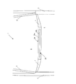
- FIG. 1 shows a vehicle after the airbag apparatus of the present embodiment is activated.
- FIG. 2 shows a part of the vehicle before the operation of the airbag apparatus of the present embodiment.
- the vehicle width direction is defined as a first direction A
- the front-rear direction orthogonal to the first direction A is defined as a second direction B.
- the airbag 10 after deployment, covers a part of the front pillar 2 of the vehicle 1, a part of the hood 4, and a part of the windshield 6 after deployment as shown in FIG. It becomes a U-shaped state. Note that a part of the hood 4 and a part of the windshield 6 may be covered so as to be developed in an I shape extending in the vehicle width direction of the vehicle 1.
- the airbag device 20 before operation is installed in a space between the hood 4 and the windshield 6 and sandwiched between the cowl tops 7.
- the airbag device 20 is covered with a cowl cover 28 having a hole 28b formed in the center of the main body 28a.
- the airbag 10 shown in FIG. 1 jumps out of the hole 28b and inflates.
- the airbag device 20 can be disposed at the position of the cowl top 7 of the vehicle 1, and the space can be used effectively, and the deployment position above the windshield 6 and the like from the installation position of the airbag 10.
- the airbag 10 can be quickly deployed above the windshield 6 and the like.
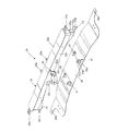
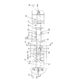
- FIG. 3 shows the airbag apparatus and bracket of the present embodiment.
- FIG. 4 is a perspective view showing a state in which the airbag device of the present embodiment is attached to a bracket.
- FIG. 5 is a plan view and a front view showing a state in which the airbag device of the present embodiment is attached to a bracket.
- 6 is a view showing a VI-VI cross section of FIG.
- FIG. 7 is a view showing a section VII-VII in FIG.
- the airbag device 20 of the present embodiment includes an airbag 10, a gas generator 11, a cover bottom member 21, and a cover lid member 22.
- the airbag device 20 is attached to the vehicle body via a bracket 29.
- the cover bottom member 21 includes a cover bottom portion 21a and a cover lower wall portion 21b protruding upward from an edge of the cover bottom portion 21a.
- the cover bottom member 21 accommodates the folded airbag 10 and the gas generator 11 installed in the airbag 10.
- the cover bottom portion 21a and the cover lower wall portion 21b of the cover bottom member 21 may be formed integrally, or may be formed by attaching different members integrally.
- the cover bottom portion 21a is formed in a shape in which a central portion in the longitudinal direction protrudes upward from both ends. That is, the cover lower wall portion 21b is formed in a substantially straight line although the center portion at the upper end is slightly higher than both ends, and the both ends are formed longer than the center portion from the upper end to the lower end.
- the cover cover member 22 protrudes in the short direction from the cover cover 22a, the cover upper wall 22b that protrudes slightly from the inner side of the edge of the cover cover 22a, and the lower outer side of the cover upper wall 22b.
- the cover lid portion 22a is a plate-like member, and is formed in a shape in which the central portion in the longitudinal direction protrudes slightly upward from both ends.
- the inner periphery of the cover upper wall portion 22b has a similar shape slightly larger than the outer periphery of the cover lower wall portion 21b, and is fitted on the outer periphery side of the cover lower wall portion 21b.
- the first attachment portion 22 c engages with the bracket 29. Further, the second attachment portion 22d and the third attachment portion 22e engage with the cowl cover 28.
- the bracket 29 is a plate-like member, and has the same shape as the surface shape of the cover bottom portion 21a of the cover bottom member 21 of the airbag device 20. That is, the central portion in the longitudinal direction is formed in a shape protruding upward from both ends.
- a support hole 29 a is formed in the bracket 29 in the vicinity of the end in the longitudinal direction.
- a screw or a pin is inserted into the support hole 29a and fastened together with the vehicle body to be fixed to the vehicle body.
- the bracket 29 By forming the bracket 29 in a shape in which the central portion in the longitudinal direction protrudes upward from both ends, the space in the lower engine room can be widely used.
- the protruding amount is preferably 20 mm or more.
- the first support portion 91 is attached to the bracket 29.
- the first support portion 91 is an L-shaped member obtained by bending a plate-like member at a right angle, and one surface 91 a is attached to the bracket 29 by welding or the like, and the other surface 91 b is attached to the upper surface of the bracket 29.
- the airbag device 20 is installed so that the first attachment portion 22c formed on the cover upper wall portion 22b of the cover lid member 22 of the first support portion 91 faces the other surface 91b, and a screw or Stop with a pin.
- flanges 91c that are orthogonal to the one surface 91a and the other surface 91b are formed. With this flange 91c, high strength can be achieved.
- the cover bottom member 21 has an L-shaped fourth attachment portion 23 formed by bending a plate-like member at a right angle in the same manner as the first support portion 91.
- the fourth attachment portion 23 attaches one surface 23 a to the short side direction of the cover lower wall portion 21 b by welding or the like, and attaches the other surface 23 b to the upper surface of the bracket 29.
- flanges 23c that are orthogonal to the one surface 23a and the other surface 23b are formed. With this flange 23c, high strength can be achieved.
- the airbag device 20 and the bracket 29 can be attached in advance, and can be easily attached only by attaching the bracket 29 to the vehicle body during assembly work. Further, when repairing, it is only necessary to remove the cover bottom member 21 and the cover lid member 22 without removing the bracket 29 from the vehicle body, so that it can be easily detached.
- the cover lid member 22 has an L-shaped stopper 24 obtained by bending a plate-like member having a higher strength than the first support portion 91 at a right angle.
- the stopper 24 has one surface 24 a attached to the longitudinal direction of the cover upper wall portion 22 b of the cover lid member 22 by welding or the like, and the other surface 24 b attached to the upper surface of the bracket 29.
- the stopper 24 of the fourth mounting portion 23 is formed with a flange 24c that is orthogonal to the one surface 24a and the other surface 24b. With this flange 24c, high strength can be achieved.
- the stopper 24 may be attached to only one of the cover upper wall portion 22b and the bracket 29, and the other may be disposed so as to face each other.
- the longitudinal direction of the cover lower wall portion 21b of the cover bottom member 21 and the cover upper wall portion 22b of the cover lid member 22 is prevented from collapsing or deforming due to the pressure when the airbag 10 is inflated.
- the bag 10 can be prevented from entering below the hood 4.
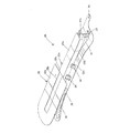
- water receiving members 25 are attached to both surfaces of the cover bottom member 21 and the cover lid member 22 in the longitudinal direction.
- the water receiving member 25 is shaped like a rain gutter having a U-shaped cross section.
- the water receiving member 25 is formed so that the end portion side is lower than the central portion side in the longitudinal direction of the cover lid member 22.
- the water receiving member 25 is attached to the cover bottom member 21 and the cover lid member 22 by a fixing member 27 such as a pin through the water receiving support member 26.
- the water receiving support member 26 may be formed in a U shape, and one end side may be fixed to the cover bottom member 21 and the cover lid member 22 and the other end side fixed to the side wall 25a of the water receiving member 25.
- the water receiving support member 26 is formed in an L shape, and one end side is fixed to the cover bottom member 21 and the cover lid member 22, and the other end side is fixed to the bottom wall 25 b of the water receiving member 25.
- the fixing by the fixing member 27 is not limited to a pin, and may be a screw, a rivet, welding, or the like.
- the water receiving member 25 may be attached to at least one of the cover bottom member 21 and the cover lid member 22.
- the airbag 10 stores the gas generator 11 in advance and is folded and stored in the cover bottom member 21. As shown in FIG. 1, the airbag 10 is deployed to the same extent as the vehicle width of the vehicle 1, but when stored, the airbag 10 is stored shorter than the vehicle width as shown in FIG. 2. Therefore, as shown in FIG. 7, the airbag 10 is positioned on both ends in the longitudinal direction of the cover bottom member 21 corresponding to the vehicle width direction at the time of installation, and on the outer side of the cover bottom member 21 in the vehicle width direction when deployed. It is preferable to fold a part to be overlapped.
- both end sides in the longitudinal direction of the cover bottom member 21 are thicker than the center portion.
- the cover bottom portion 21a of the cover bottom member 21 is formed in a shape in which the center portion in the longitudinal direction protrudes upward from both ends, and the storage space of the cover bottom member 21 is deeper at both ends in the longitudinal direction than the center portion.
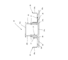
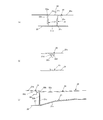
- FIG. 8 is a perspective view showing a state in which a cowl cover is attached to the airbag device of the present embodiment.
- FIG. 9 is a plan view showing a state in which a cowl cover is attached to the airbag apparatus of the present embodiment.
- FIG. 10 is a view showing each XX cross section of FIG.
- FIG. 10A is a view showing a cross section Xa-Xa in FIG. 9, and FIG. 10B is a view showing a cross section Xb-Xb in FIG.
- FIG. 10C is a diagram showing a cross section Xc-Xc in FIG.
- the airbag device 20 of the present embodiment is covered with a cowl cover 28 at the top.
- a cowl cover 28 at the top.
- the hole 28b is formed in the center of the main body 28a of the cowl cover 28, a part of the cover lid portion 22a of the cover lid member 22 is exposed to the outside.
- the cover lid portion 22a is preferably cut at a position corresponding to the hole 28b of the cowl cover 28.
- the cowl cover 28 is a plate-like member and has a surface shape similar to the surface shape of the cover lid portion 22 a of the cover lid member 22. Therefore, when the cowl cover 28 is attached to the air bag device 20 includes a lid end 22a 1 of the cowl cover 28 and the cover lid portion 22a, so that the contact overlap around the hole 28b. As shown in FIG. 10A, the portion corresponding to the hole 28 b of the cover lid portion 22 a has a thickness equivalent to the thickness of the cowl cover 28 than the surface of the cowl cover 28 in the cross-section in the short direction of the cover lid member 22. It will be in a state where it is only recessed. However, it is preferable that a very small gap for draining is formed between the cowl cover 28 and the cover lid portion 22a.
- the cowl cover 28 is attached by the second attachment portion 22d and the third attachment portion 22e of the cover lid member 22.
- the upper surfaces of the second attachment portion 22d and the third attachment portion 22e are preferably flush with the upper surface of the cover lid portion 22a.
- the second attachment portion 22d is formed to protrude from both ends in the longitudinal direction.
- a hole 22d 1 is formed in the second attachment portion 22d.
- the engagement portion 28c of the cowl cover 28 and the hole 22d 1 as shown in FIG. 22 is attached.
- the third attachment portion 22e is formed so as to protrude from at least one of the short sides.
- the cowl cover 28 is attached to the third attachment portion 22e by screws, pins, rivets or the like.
- the airbag device can be disposed at a position where the normal cowl top 7 between the hood 4 and the window 6 is disposed. It can be used. Further, since only the cowl cover 28 can be processed and connected, it can be attached to an existing vehicle.
- cowl cover 28 and the cover lid member 22 are attached so as to overlap with each other around the hole 28b, even if some positional deviation occurs, the positional deviation is not noticeable, and the influence on the appearance quality is minimized. It becomes possible.
- the portion corresponding to the hole 28b of the cover lid portion 22a is in a state of being recessed from the surface of the cowl cover 28 by the thickness of the cowl cover 28 in the cross-section in the short direction of the cover lid member 22. Since a very small gap is formed between the cover 28 and the cover lid member 22, water can flow downward from the gap and drain through the water receiving member 25 without accumulating water.
- FIG. 11 is a view showing another form of the cover lid member 22.
- a lid end 22 a 1 is formed on the periphery of the cover lid member 22.
- the lid end portion 22a 1 is formed of a step that is approximately as thin as the cowl cover 28 from the upper surface of the cover lid portion 22a.
- This cover end 22a 1 by attaching the cowl cover 28 overlapping with an upper surface of the cowl cover 28, the upper surface of the cover lid 22a is formed on the same surface or substantially the same plane. Therefore, it is possible to improve the appearance when the airbag device 20 is installed in the vehicle 1.
- the airbag device 20 jets gas into the airbag 10 and the airbag 10 that covers at least a part of the hood 4 or the windshield 6 outside the vehicle 1 when deployed.
- the cowl cover 28 has a hole 28b formed at the center, and the periphery of the hole 28b is attached so as to overlap the cover lid portion 22a of the cover lid member 22. Even when the positional deviation occurs, the positional deviation is not conspicuous, and the influence on the appearance quality can be minimized.
- the airbag apparatus 20 of this embodiment is provided with the water receiving part 25 which inclines below toward the edge part from the center part in the longitudinal direction of the cover cover member 22, and the cover cover member 22 is a cover cover. Since the cover wall portion 22b protrudes from the portion 22a toward the cover bottom member 21 and the water receiving portion 25 is attached to a surface extending in the longitudinal direction of the cover wall portion 22b, the water flow is directed to the side of the engine room. It becomes possible to guide.
- the cowl cover 28 is connected to the cowl tops 7 that are installed between the hood 4 and the windshield 6 at both ends in the vehicle width direction, so that it is easy for the vehicle body. It can be assembled.
Landscapes
- Engineering & Computer Science (AREA)
- Mechanical Engineering (AREA)
- Body Structure For Vehicles (AREA)
- Air Bags (AREA)
Abstract
【課題】 迅速に展開できると共に、既存の車体に取り付けることが可能なエアバッグ装置を提供する。【解決手段】 エアバッグ装置(20)は、展開時に車両の外側で少なくともフード(4)又はウインドシールド(6)の一部を覆うエアバッグ(10)と、エアバッグ(10)内にガスを噴出するガス発生器(11)と、膨張前のエアバッグ(10)及びガス発生器(11)を収納するカバー底部材(21)と、エアバッグ(10)を収納したカバー底部材(21)を覆うカバー蓋部(22a)を有するカバー蓋部材(22)と、フード(4)とウインドシールド(6)の間でカバー蓋部(22a)に取り付けられるカウルカバー(28)と、を備えることを特徴とする。
Description
本発明は、車両が衝突対象と衝突した時等の緊急時に、インフレータ等のガス発生器からのガスにより車両外部に膨張展開して、衝突対象や車両にかかる衝撃を緩和するためのエアバッグ装置の技術分野に属するものである。
従来、車両と歩行者等との衝突時に、エアバッグを車両のボンネット後方及びピラー部分の外側に膨張させ、該歩行者等が車両と再衝突する衝撃を緩和させるものがある。
例えば、ボンネットフードの後縁とカウルトップの前縁との間に車体左右方向に延びるエアバッグモジュールを配置し、空気吸入口やワイパー等の配置に影響を与えることなく、高剛性のダンパハウジングで支持したエアバッグ装置が開示されている(特許文献1参照)。
しかしながら、特許文献1に記載されたエアバッグ装置は、カウルトップよりも前方に設置されているので、エアバッグがウインドシールド又はフロントピラーまで展開するのに要する時間が長かった。また、ボンネットフードとカウルトップの間にエアバッグ装置を設置するためのスペースが必要なので、ボンネットフードを変更する必要があり、既存の車体に取り付けることはできなかった。
本発明は、このような事情に鑑みてなされたものであって、迅速に展開できると共に、既存の車体に取り付けることが可能なエアバッグ装置を提供することである。
本実施形態のエアバッグ装置は、
展開時に車両の外側で少なくともフード又はウインドシールドの一部を覆うエアバッグと、
前記エアバッグ内にガスを噴出するガス発生器と、
膨張前の前記エアバッグ及び前記ガス発生器を収納するカバー底部材と、
前記エアバッグを収納した前記カバー底部材を覆うカバー蓋部を有するカバー蓋部材と、
前記フードと前記ウインドシールドの間で前記カバー蓋部に取り付けられるカウルカバーと、
を備える
ことを特徴とする。
展開時に車両の外側で少なくともフード又はウインドシールドの一部を覆うエアバッグと、
前記エアバッグ内にガスを噴出するガス発生器と、
膨張前の前記エアバッグ及び前記ガス発生器を収納するカバー底部材と、
前記エアバッグを収納した前記カバー底部材を覆うカバー蓋部を有するカバー蓋部材と、
前記フードと前記ウインドシールドの間で前記カバー蓋部に取り付けられるカウルカバーと、
を備える
ことを特徴とする。
本実施形態のエアバッグ装置は、
前記カウルカバーは、中央部に孔が形成され、前記孔の周囲が前記カバー蓋部の蓋端部にオーバーラップして取り付けられる
ことを特徴とする。
前記カウルカバーは、中央部に孔が形成され、前記孔の周囲が前記カバー蓋部の蓋端部にオーバーラップして取り付けられる
ことを特徴とする。
本実施形態のエアバッグ装置は、
少なくとも前記カバー蓋部材又は前記カバー底部材のいずれか1つに、長手方向における中央部から端部に向けて下方に傾斜して取り付けられる水受け部を備える
ことを特徴とする。
少なくとも前記カバー蓋部材又は前記カバー底部材のいずれか1つに、長手方向における中央部から端部に向けて下方に傾斜して取り付けられる水受け部を備える
ことを特徴とする。
本実施形態のエアバッグ装置は、
前記カウルカバーは、前記フードと前記ウインドシールドの間で車幅方向両端側に設置されるカウルトップに連結される
ことを特徴とする。
前記カウルカバーは、前記フードと前記ウインドシールドの間で車幅方向両端側に設置されるカウルトップに連結される
ことを特徴とする。
本実施形態のエアバッグ装置は、
展開時に車両の外側で少なくともフード又はウインドシールドの一部を覆うエアバッグと、
前記エアバッグ内にガスを噴出するガス発生器と、
膨張前の前記エアバッグ及び前記ガス発生器を収納するカバー底部材と、
前記エアバッグを収納した前記カバー底部材を覆うカバー蓋部を有するカバー蓋部材と、
前記フードと前記ウインドシールドの間で前記カバー蓋部の取り付けられるカウルカバーと、
を備えるので、
前記ウインドシールドに近接して配置することができ、前記エアバッグを迅速に膨張させることが可能となると共に、スペースを有効に活用することができ、既存の車体にも取り付けることが可能となる。
展開時に車両の外側で少なくともフード又はウインドシールドの一部を覆うエアバッグと、
前記エアバッグ内にガスを噴出するガス発生器と、
膨張前の前記エアバッグ及び前記ガス発生器を収納するカバー底部材と、
前記エアバッグを収納した前記カバー底部材を覆うカバー蓋部を有するカバー蓋部材と、
前記フードと前記ウインドシールドの間で前記カバー蓋部の取り付けられるカウルカバーと、
を備えるので、
前記ウインドシールドに近接して配置することができ、前記エアバッグを迅速に膨張させることが可能となると共に、スペースを有効に活用することができ、既存の車体にも取り付けることが可能となる。
本実施形態のエアバッグ装置は、
前記カウルカバーは、中央部に孔が形成され、前記孔の周囲が前記カバー蓋部の蓋端部にオーバーラップして取り付けられるので、
多少の位置ズレが生じた場合でも、位置ズレが目立たず、外観品質に与える影響を最小限に抑えることが可能となる。
前記カウルカバーは、中央部に孔が形成され、前記孔の周囲が前記カバー蓋部の蓋端部にオーバーラップして取り付けられるので、
多少の位置ズレが生じた場合でも、位置ズレが目立たず、外観品質に与える影響を最小限に抑えることが可能となる。
本実施形態のエアバッグ装置は、
少なくとも前記カバー蓋部材又は前記カバー底部材のいずれか1つに、長手方向における中央部から端部に向けて下方に傾斜して取り付けられる水受け部を備えるので、
水の流れをエンジンルームの側方に導くことが可能となる。
少なくとも前記カバー蓋部材又は前記カバー底部材のいずれか1つに、長手方向における中央部から端部に向けて下方に傾斜して取り付けられる水受け部を備えるので、
水の流れをエンジンルームの側方に導くことが可能となる。
本実施形態のエアバッグ装置は、
前記カウルカバーは、前記フードと前記ウインドシールドの間で車幅方向両端側に設置されるカウルトップに連結されるので、
車体に対して容易に組み付けることが可能となる。
前記カウルカバーは、前記フードと前記ウインドシールドの間で車幅方向両端側に設置されるカウルトップに連結されるので、
車体に対して容易に組み付けることが可能となる。
以下、図面を用いて、本発明にかかる実施の形態を説明する。
図1は、本実施形態のエアバッグ装置が作動後の車両を示す。図2は、本実施形態のエアバッグ装置の作動前の車両の一部を示す。なお、図1の車両において、車幅方向を第1方向A、第1方向Aに直交する前後方向を第2方向Bと定義する。
本実施形態のエアバッグ装置20では、展開後、図1に示すように、エアバッグ10が、車両1のフロントピラー2の一部、フード4の一部、及びウインドシールド6の一部を覆うU字状の状態となる。なお、フード4の一部及びウインドシールド6の一部を覆い車両1の車幅方向に延びるI字状に展開してもよい。
図2に示すように、作動前のエアバッグ装置20は、フード4とウインドシールド6の間の隙間で、カウルトップ7に挟まれた箇所に設置される。エアバッグ装置20は、本体28aの中央に孔28bが形成されたカウルカバー28で覆われる。図1に示したエアバッグ10は、この孔28bから飛び出して膨張する。
したがって、エアバッグ装置20を車両1のカウルトップ7の位置に配置することが可能となり、スペースを有効に活用することができると共に、エアバッグ10の設置位置からウインドシールド6等の上方の展開位置までの距離が近くなり、エアバッグ10をウインドシールド6等の上方に迅速に展開させることが可能となる。
図3は、本実施形態のエアバッグ装置とブラケットを示す。図4は、本実施形態のエアバッグ装置をブラケットに取り付けた状態を示す斜視図である。図5は、本実施形態のエアバッグ装置をブラケットに取り付けた状態を示す平面図と正面図である。図6は、図5のVI-VI断面を示す図である。図7は、図5のVII-VII断面を示す図である。
本実施形態のエアバッグ装置20は、エアバッグ10と、ガス発生器11と、カバー底部材21と、カバー蓋部材22と、を備える。エアバッグ装置20は、ブラケット29を介して車体に取り付けられる。
カバー底部材21は、カバー底部21aと、カバー底部21aの端縁から上方に突出するカバー下壁部21bと、を有する。カバー底部材21は、折り畳まれたエアバッグ10及びエアバッグ10内に設置されたガス発生器11を収納する。カバー底部材21のカバー底部21aとカバー下壁部21bは、一体に形成してもよいし、別々の部材を一体に取り付けて形成してもよい。
カバー底部21aは、長手方向における中央部が両端よりも上方に突出した形状に形成される。すなわち、カバー下壁部21bは、上端の中央部が両端よりも若干高いがほぼ直線状に形成されて、上端から下端までの距離が中央部よりも両端が長く形成される。
カバー蓋部材22は、カバー蓋部22aと、カバー蓋部22aの端縁の若干内側から下方に突出するカバー上壁部22bと、カバー上壁部22bの下方外側から短手方向にそれぞれ突出した第1取付部22cと、カバー蓋部22aから車幅方向に突出した第2取付部22dと、カバー蓋部22aから短手方向の一方に突出した第3取付部22eと、を有する。
カバー蓋部22aは、板状の部材であって、長手方向における中央部が両端よりも若干上方に突出した形状に形成される。カバー上壁部22bの内周は、カバー下壁部21bの外周よりも若干大きい相似形状であって、カバー下壁部21bの外周側に嵌め込まれる。
第1取付部22cは、ブラケット29に係合する。また、第2取付部22d及び第3取付部22eはカウルカバー28に係合する。
ブラケット29は、板状の部材であって、エアバッグ装置20のカバー底部材21のカバー底部21aの面形状と同様の形状を有する。すなわち、長手方向における中央部が両端よりも上方に突出した形状に形成される。ブラケット29には、長手方向の端部近傍に支持孔29aが形成される。支持孔29aに螺子又はピン等を挿入し、車体と共締めされることで、車体に固定される。
ブラケット29を、長手方向における中央部が両端よりも上方に突出した形状に形成することで、下方のエンジンルームのスペースを広く使用することが可能となる。なお、突出する量は、20mm以上あると好ましい。
ブラケット29には、第1支持部91が取り付けられる。第1支持部91は、板状の部材を直角に屈曲したL字状の部材であって、一方の面91aをブラケット29に溶接等によって取り付け、他方の面91bをブラケット29の上面に対して垂直方向又は略垂直方向となるように取り付ける。そして、他方の面91bに対して第1支持部91のカバー蓋部材22のカバー上壁部22bに形成された第1取付部22cが対向するようにエアバッグ装置20を設置して、螺子又はピン等で止める。第1支持部91のL字状の端部には、一方の面91a及び他方の面91bにそれぞれに直交するフランジ91cが形成されている。このフランジ91cによって、高強度とすることが可能となる。
カバー底部材21には、第1支持部91と同様に板状の部材を直角に屈曲したL字状の第4取付部23を有する。第4取付部23は、一方の面23aをカバー下壁部21bの短手方向に溶接等によって取り付け、他方の面23bをブラケット29の上面に取り付ける。第4取付部23のL字状の端部には、一方の面23a及び他方の面23bにそれぞれに直交するフランジ23cが形成されている。このフランジ23cによって、高強度とすることが可能となる。
このように、あらかじめエアバッグ装置20とブラケット29を取り付けることができ、組み立て作業時には、ブラケット29を車体に取り付けるだけで容易に装着することが可能となる。また、修理の際には、ブラケット29を車体から外さず、カバー底部材21及びカバー蓋部材22のみを取り外せばよいので、容易に脱着することが可能となる。
また、カバー蓋部材22には、第1支持部91より高強度の板状の部材を直角に屈曲したL字状のストッパ24を有する。ストッパ24は、一方の面24aをカバー蓋部材22のカバー上壁部22bの長手方向に溶接等によって取り付け、他方の面24bをブラケット29の上面に取り付ける。第4取付部23のストッパ24には、一方の面24a及び他方の面24bにそれぞれに直交するフランジ24cが形成されている。このフランジ24cによって、高強度とすることが可能となる。なお、ストッパ24は、カバー上壁部22b又はブラケット29のどちらか一方のみに取り付けられ、他方は対向して配置する構造でもよい。
したがって、エアバッグ10の膨張時の圧力によって、カバー底部材21のカバー下壁部21b及びカバー蓋部材22のカバー上壁部22bの長手方向が倒壊又は変形することを抑制し、その結果、エアバッグ10がフード4の下方に進入することを抑制することが可能となる。
さらに、カバー底部材21及びカバー蓋部材22の長手方向の両面には、水受け部材25が取り付けられている。水受け部材25は、断面U字状の雨樋のような形状をしている。水受け部材25は、カバー蓋部材22の長手方向の中央部側より端部側が下方に形成される。
水受け部材25は、水受け支持部材26を介してカバー底部材21及びカバー蓋部材22にピン等の固着部材27によって取り付けられる。水受け支持部材26は、一例として、U字状に形成され、一端側をカバー底部材21及びカバー蓋部材22に、他端側を水受け部材25の側壁25aに固着されればよい。また、水受け支持部材26は、他の例として、L字状に形成され、一端側をカバー底部材21及びカバー蓋部材22に、他端側を水受け部材25の底壁25bに固着されればよい。なお、固着部材27による固着は、ピンに限らず、螺子、リベット、又は溶接等でもよい。なお、水受け部材25は、少なくともカバー底部材21及びカバー蓋部材22のいずれか1つに取り付ければよい。
このように、水受け部材25を取り付けることによって、水の流れをエンジンルームの側方に導くことが可能となる。
エアバッグ10は、あらかじめガス発生器11を収納し、折り畳まれてカバー底部材21に収納される。エアバッグ10は、図1に示したように、車両1の車幅と同程度に展開するが、収納時には、図2に示したように、車幅よりも短く収納される。そのため、エアバッグ10は、図7に示すように、取付時の車幅方向に対応するカバー底部材21の長手方向の両端側に、展開時にカバー底部材21よりも車幅方向の外側に位置する一部を重ねて折り畳むことが好ましい。
このように折り畳むことで、カバー底部材21よりも車幅方向の外側に位置するエアバッグ10の膨張速度を速くさせることが可能となる。なお、このように折り畳まれたエアバッグ10は、カバー底部材21の長手方向の両端側が中央部よりも厚くなる。しかしながら、カバー底部材21のカバー底部21aは、長手方向における中央部が両端よりも上方に突出した形状に形成され、カバー底部材21の収納スペースは、長手方向の両端側が中央部よりも深いので、エアバッグ10を的確に収納することが可能となる。
図8は、本実施形態のエアバッグ装置にカウルカバーを取り付けた状態を示す斜視図である。図9は、本実施形態のエアバッグ装置にカウルカバーを取り付けた状態を示す平面図である。図10は、図9の各X-X断面を示す図である。
図10(a)は、図9のXa-Xa断面を示す図、図10(b)は、図9のXb-Xb断面を示す図である。図10(c)は、図9のXc-Xc断面を示す図である。
本実施形態のエアバッグ装置20は、上方をカウルカバー28で覆われる。しかしながら、カウルカバー28の本体28aには、中央に孔28bが形成されているので、カバー蓋部材22のカバー蓋部22aの一部は外側に露出することとなる。また、膨張時には、カバー蓋部22aは、カウルカバー28の孔28bに対応する位置で開削することが好ましい。
カウルカバー28は、板状の部材であって、カバー蓋部材22のカバー蓋部22aの面形状と同様の面形状を有する。したがって、カウルカバー28がエアバッグ装置20に取り付けられる際には、カウルカバー28とカバー蓋部22aの蓋端部22a1は、孔28bの周囲でオーバーラップして接触することとなる。そして、図10(a)に示すように、カバー蓋部22aの孔28bに対応する部分は、カバー蓋部材22の短手方向の断面において、カウルカバー28の表面よりもカウルカバー28の厚み分だけ凹んだ状態となる。ただし、カウルカバー28とカバー蓋部22aの間には、水抜き用の極小さい隙間が形成されることが好ましい。
カウルカバー28は、カバー蓋部材22の第2取付部22d及び第3取付部22eで取り付けられる。第2取付部22d及び第3取付部22eの上面は、カバー蓋部22aの上面と面一であることが好ましい。
第2取付部22dは、長手方向の両端から突出して形成される。第2取付部22dには、孔22d1が形成され、図10(b)に示すようなカウルカバー28の係合部28cと孔22d1が係合することによって、カウルカバー28がカバー蓋部材22に取り付けられる。
第3取付部22eは、短手方向の少なくとも一方から突出して形成される。カウルカバー28は、第3取付部22eに螺子、ピン、又はリベット等によって取り付けられる。
このように、カウルカバー28をカバー蓋部材22に取り付けることによって、フード4とウインドウ6の間の通常カウルトップ7が配置される位置にエアバッグ装置を配置することができるので、スペースを有効に活用することが可能となる。また、カウルカバー28のみを加工して連結することができるので、既存の車両にも取り付けることが可能となる。
また、カウルカバー28とカバー蓋部材22は孔28bの周囲でオーバーラップして取り付けられるので、多少の位置ズレが生じた場合でも、位置ズレが目立たず、外観品質に与える影響を最小限に抑えることが可能となる。
さらに、カバー蓋部22aの孔28bに対応する部分は、カバー蓋部材22の短手方向の断面において、カウルカバー28の表面よりもカウルカバー28の厚み分だけ凹んだ状態となるが、カウルカバー28とカバー蓋部材22には極小の隙間を形成してあるので、水をためることなく、該隙間から下方へ流し、水受け部材25を通って排水することが可能となる。
図11は、カバー蓋部材22の他の形態を示す図である。
図11に示す他の実施形態では、カバー蓋部材22の周縁に蓋端部22a1が形成されている。蓋端部22a1は、カバー蓋部22aの上面からカウルカバー28の厚み程度低い段差からなる。この蓋端部22a1にカウルカバー28をオーバーラップして取り付けることで、カウルカバー28の上面と、カバー蓋部22aの上面が同一面又は略同一面に形成される。したがって、エアバッグ装置20を車両1に設置した際の見栄えを良くすることが可能となる。
以上、説明したように、本実施形態のエアバッグ装置20は、展開時に車両1の外側で少なくともフード4又はウインドシールド6の一部を覆うエアバッグ10と、エアバッグ10内にガスを噴出するガス発生器11と、膨張前のエアバッグ10及びガス発生器11を収納するカバー底部材21と、エアバッグ10を収納したカバー底部材21を覆うカバー蓋部22aを有するカバー蓋部材22と、フード4とウインドシールド6の間でカバー蓋部22aの上面に取り付けられるカウルカバー28と、を備えるので、ウインドシールド6に近接して配置することができ、エアバッグ10を迅速に膨張させることが可能となると共に、スペースを有効に活用することができ、既存の車体にも取り付けることが可能となる。
また、本実施形態のエアバッグ装置20では、カウルカバー28は、中央部に孔28bが形成され、孔28bの周囲がカバー蓋部材22のカバー蓋部22aにオーバーラップして取り付けられるので、多少の位置ズレが生じた場合でも、位置ズレが目立たず、外観品質に与える影響を最小限に抑えることが可能となる。
また、本実施形態のエアバッグ装置20は、カバー蓋部材22の長手方向における中央部から端部に向けて下方に傾斜して取り付けられる水受け部25を備え、カバー蓋部材22は、カバー蓋部22aからカバー底部材21側に突出するカバー壁部22bを有し、水受け部25は、カバー壁部22bの長手方向に延びる面に取り付けられるので、水の流れをエンジンルームの側方に導くことが可能となる。
また、本実施形態のエアバッグ装置20は、カウルカバー28は、フード4とウインドシールド6の間で車幅方向両端側に設置されるカウルトップ7に連結されるので、車体に対して容易に組み付けることが可能となる。
なお、前述の例は、本発明に係るエアバッグ装置20の実施の形態の一例に過ぎず、本発明は特許請求の範囲に記載された事項の範囲内でエアバッグ装置20の各構成要素は種々変形又は組み合わせ可能である。
1…車両、2…フロントピラー、3…フェンダ、4…フード、5…ルーフ、6…ウインドシールド、7…カウルトップ、10…エアバッグ、11…ガス発生器、20…エアバッグ装置、21…カバー底部材、22…カバー蓋部材、23…第4取付部、24…ストッパ、25…水受け部材、28…カウルカバー、29…ブラケット
Claims (4)
- 展開時に車両の外側で少なくともフード又はウインドシールドの一部を覆うエアバッグと、
前記エアバッグ内にガスを噴出するガス発生器と、
膨張前の前記エアバッグ及び前記ガス発生器を収納するカバー底部材と、
前記エアバッグを収納した前記カバー底部材を覆うカバー蓋部を有するカバー蓋部材と、
前記フードと前記ウインドシールドの間で前記カバー蓋部に取り付けられるカウルカバーと、
を備える
ことを特徴とするエアバッグ装置。 - 前記カウルカバーは、中央部に孔が形成され、前記孔の周囲が前記カバー蓋部の蓋端部にオーバーラップして取り付けられる
ことを特徴とする請求項1に記載のエアバッグ装置。 - 少なくとも前記カバー蓋部材又は前記カバー底部材のいずれか1つに、長手方向における中央部から端部に向けて下方に傾斜して取り付けられる水受け部を備える
ことを特徴とする請求項1又は請求項2に記載のエアバッグ装置。 - 前記カウルカバーは、前記フードと前記ウインドシールドの間で車幅方向両端側に設置されるカウルトップに連結される
ことを特徴とする請求項1乃至請求項3のいずれか1つに記載のエアバッグ装置。
Priority Applications (3)
| Application Number | Priority Date | Filing Date | Title |
|---|---|---|---|
| CN201580002860.1A CN105873802B (zh) | 2014-02-19 | 2015-02-03 | 气囊装置 |
| US15/119,509 US10202097B2 (en) | 2014-02-19 | 2015-02-03 | Airbag unit |
| EP15752595.7A EP3109100B1 (en) | 2014-02-19 | 2015-02-03 | Airbag apparatus |
Applications Claiming Priority (2)
| Application Number | Priority Date | Filing Date | Title |
|---|---|---|---|
| JP2014029770A JP6301151B2 (ja) | 2014-02-19 | 2014-02-19 | エアバッグ装置 |
| JP2014-029770 | 2014-02-19 |
Publications (1)
| Publication Number | Publication Date |
|---|---|
| WO2015125598A1 true WO2015125598A1 (ja) | 2015-08-27 |
Family
ID=53878109
Family Applications (1)
| Application Number | Title | Priority Date | Filing Date |
|---|---|---|---|
| PCT/JP2015/052931 Ceased WO2015125598A1 (ja) | 2014-02-19 | 2015-02-03 | エアバッグ装置 |
Country Status (5)
| Country | Link |
|---|---|
| US (1) | US10202097B2 (ja) |
| EP (1) | EP3109100B1 (ja) |
| JP (1) | JP6301151B2 (ja) |
| CN (1) | CN105873802B (ja) |
| WO (1) | WO2015125598A1 (ja) |
Families Citing this family (2)
| Publication number | Priority date | Publication date | Assignee | Title |
|---|---|---|---|---|
| JP6269524B2 (ja) * | 2015-02-10 | 2018-01-31 | トヨタ自動車株式会社 | 歩行者保護エアバッグ装置 |
| JP2021138290A (ja) * | 2020-03-05 | 2021-09-16 | 本田技研工業株式会社 | エアバッグ配置構造 |
Citations (2)
| Publication number | Priority date | Publication date | Assignee | Title |
|---|---|---|---|---|
| JP2007055569A (ja) * | 2005-07-26 | 2007-03-08 | Honda Motor Co Ltd | 衝突物保護装置 |
| JP2007196800A (ja) * | 2006-01-25 | 2007-08-09 | Toyota Motor Corp | 車両用フードエアバッグ装置のシール構造 |
Family Cites Families (18)
| Publication number | Priority date | Publication date | Assignee | Title |
|---|---|---|---|---|
| JP2600019Y2 (ja) * | 1993-03-31 | 1999-09-27 | 富士重工業株式会社 | 自動車の歩行者保護用エアバッグ装置 |
| FR2771980B1 (fr) * | 1997-12-05 | 2000-02-18 | Plastic Omnium Cie | Cassette d'auvent pour vehicule automobile |
| JP3687418B2 (ja) * | 1998-06-26 | 2005-08-24 | 日産自動車株式会社 | 跳ね上げフード |
| JP2003095044A (ja) * | 2001-09-06 | 2003-04-03 | Takata Corp | 外面展開型エアバッグ装置 |
| JP3791379B2 (ja) * | 2001-10-02 | 2006-06-28 | トヨタ自動車株式会社 | フードエアバッグ装置 |
| DE60214313T2 (de) * | 2001-10-22 | 2007-03-29 | Takata Corp. | Externe Airbagvorrichtung |
| JP3951747B2 (ja) | 2002-03-01 | 2007-08-01 | タカタ株式会社 | 外面展開型エアバッグ装置 |
| JP3975866B2 (ja) * | 2002-08-30 | 2007-09-12 | 豊田合成株式会社 | 歩行者保護用エアバッグ装置 |
| CN1521062A (zh) | 2003-01-29 | 2004-08-18 | 高田株式会社 | 外部展开的气囊装置 |
| US7341274B2 (en) * | 2004-03-17 | 2008-03-11 | Toyoda Gosei Co., Ltd. | Pedestrian airbag system |
| US7243754B2 (en) * | 2004-03-17 | 2007-07-17 | Toyoda Gosei Co., Ltd. | Pedestrian airbag system |
| JP2006062488A (ja) * | 2004-08-26 | 2006-03-09 | Honda Motor Co Ltd | 歩行者保護用エアバッグ装置 |
| DE102006033670B4 (de) * | 2005-07-26 | 2011-08-25 | Honda Motor Co., Ltd. | Fahrzeug mit Kollisionsobjekt-Schutzeinrichtung |
| JP4621119B2 (ja) | 2005-11-18 | 2011-01-26 | 本田技研工業株式会社 | 衝突物保護装置 |
| JP2007196787A (ja) * | 2006-01-25 | 2007-08-09 | Takata Corp | 歩行者用エアバッグ装置 |
| JP4187260B2 (ja) * | 2006-01-25 | 2008-11-26 | トヨタ自動車株式会社 | 車両用フードエアバッグ装置 |
| JP4113894B2 (ja) | 2006-01-25 | 2008-07-09 | トヨタ自動車株式会社 | 車両用フードエアバッグ装置 |
| JP6375484B2 (ja) * | 2013-04-26 | 2018-08-22 | Joyson Safety Systems Japan株式会社 | エアバッグ装置及びエアバッグの折り畳み方法 |
-
2014
- 2014-02-19 JP JP2014029770A patent/JP6301151B2/ja active Active
-
2015
- 2015-02-03 US US15/119,509 patent/US10202097B2/en active Active
- 2015-02-03 CN CN201580002860.1A patent/CN105873802B/zh active Active
- 2015-02-03 WO PCT/JP2015/052931 patent/WO2015125598A1/ja not_active Ceased
- 2015-02-03 EP EP15752595.7A patent/EP3109100B1/en active Active
Patent Citations (2)
| Publication number | Priority date | Publication date | Assignee | Title |
|---|---|---|---|---|
| JP2007055569A (ja) * | 2005-07-26 | 2007-03-08 | Honda Motor Co Ltd | 衝突物保護装置 |
| JP2007196800A (ja) * | 2006-01-25 | 2007-08-09 | Toyota Motor Corp | 車両用フードエアバッグ装置のシール構造 |
Also Published As
| Publication number | Publication date |
|---|---|
| CN105873802B (zh) | 2019-01-08 |
| EP3109100B1 (en) | 2019-04-03 |
| EP3109100A4 (en) | 2017-10-25 |
| EP3109100A1 (en) | 2016-12-28 |
| CN105873802A (zh) | 2016-08-17 |
| US20170008483A1 (en) | 2017-01-12 |
| US10202097B2 (en) | 2019-02-12 |
| JP6301151B2 (ja) | 2018-03-28 |
| JP2015151116A (ja) | 2015-08-24 |
Similar Documents
| Publication | Publication Date | Title |
|---|---|---|
| JP5846192B2 (ja) | 車両用歩行者保護エアバッグ装置 | |
| JP2009029398A (ja) | 車両用衝撃センサの取付構造 | |
| JP4308643B2 (ja) | 歩行者用エアバッグ装置 | |
| JP2007196796A (ja) | 車両用フードエアバッグ装置 | |
| JP6406686B2 (ja) | エアバッグ装置 | |
| KR101027490B1 (ko) | 차량용 후드 에어백 장치 | |
| US7766375B2 (en) | Pedestrian airbag apparatus | |
| JP6301151B2 (ja) | エアバッグ装置 | |
| JP2015136978A (ja) | フード付け車両用歩行者保護エアバッグ装置の搭載構造 | |
| KR20080080222A (ko) | 차량용 후드에어백장치 | |
| JP2015123775A (ja) | 歩行者保護エアバッグ装置 | |
| JP5335513B2 (ja) | ドアマウントエアバッグの取付部構造 | |
| JP6277733B2 (ja) | 歩行者用エアバッグ装置及び自動車 | |
| JP6579518B2 (ja) | 歩行者用エアバッグ装置 | |
| JP5262268B2 (ja) | ドア構造 | |
| JP5215247B2 (ja) | エアバッグ装置のバッグカバー | |
| JP5900483B2 (ja) | 歩行者保護エアバッグ装置のフード搭載構造 | |
| CN106476742B (zh) | 带有安全气囊装置的车身 | |
| JP6205296B2 (ja) | 自動車用のインストルメントパネルを有するアセンブリ及びニーエアバッグ | |
| JP2009161164A (ja) | エアバッグ装置 | |
| JP2005343202A (ja) | 歩行者用エアバッグ装置 | |
| JP2005343201A (ja) | 歩行者用エアバッグ装置 | |
| JP2006096290A (ja) | 歩行者用エアバッグ装置 | |
| JP2005343203A (ja) | 歩行者用エアバッグ装置 |
Legal Events
| Date | Code | Title | Description |
|---|---|---|---|
| 121 | Ep: the epo has been informed by wipo that ep was designated in this application |
Ref document number: 15752595 Country of ref document: EP Kind code of ref document: A1 |
|
| REEP | Request for entry into the european phase |
Ref document number: 2015752595 Country of ref document: EP |
|
| WWE | Wipo information: entry into national phase |
Ref document number: 2015752595 Country of ref document: EP |
|
| WWE | Wipo information: entry into national phase |
Ref document number: 15119509 Country of ref document: US |
|
| NENP | Non-entry into the national phase |
Ref country code: DE |