WO2015125649A1 - マニピュレータ装置の制御方法 - Google Patents
マニピュレータ装置の制御方法 Download PDFInfo
- Publication number
- WO2015125649A1 WO2015125649A1 PCT/JP2015/053539 JP2015053539W WO2015125649A1 WO 2015125649 A1 WO2015125649 A1 WO 2015125649A1 JP 2015053539 W JP2015053539 W JP 2015053539W WO 2015125649 A1 WO2015125649 A1 WO 2015125649A1
- Authority
- WO
- WIPO (PCT)
- Prior art keywords
- manipulators
- joint
- manipulator
- distance
- maximum
- Prior art date
- Legal status (The legal status is an assumption and is not a legal conclusion. Google has not performed a legal analysis and makes no representation as to the accuracy of the status listed.)
- Ceased
Links
- RTMQIRDUBCMDSV-UHFFFAOYSA-N CCCC(C)C(F)(F)F Chemical compound CCCC(C)C(F)(F)F RTMQIRDUBCMDSV-UHFFFAOYSA-N 0.000 description 1
Images





Classifications
-
- B—PERFORMING OPERATIONS; TRANSPORTING
- B25—HAND TOOLS; PORTABLE POWER-DRIVEN TOOLS; MANIPULATORS
- B25J—MANIPULATORS; CHAMBERS PROVIDED WITH MANIPULATION DEVICES
- B25J9/00—Program-controlled manipulators
- B25J9/16—Program controls
- B25J9/1679—Program controls characterised by the tasks executed
- B25J9/1682—Dual arm manipulator; Coordination of several manipulators
-
- A—HUMAN NECESSITIES
- A61—MEDICAL OR VETERINARY SCIENCE; HYGIENE
- A61B—DIAGNOSIS; SURGERY; IDENTIFICATION
- A61B1/00—Instruments for performing medical examinations of the interior of cavities or tubes of the body by visual or photographical inspection, e.g. endoscopes; Illuminating arrangements therefor
- A61B1/00002—Operational features of endoscopes
- A61B1/00004—Operational features of endoscopes characterised by electronic signal processing
- A61B1/00006—Operational features of endoscopes characterised by electronic signal processing of control signals
-
- A—HUMAN NECESSITIES
- A61—MEDICAL OR VETERINARY SCIENCE; HYGIENE
- A61B—DIAGNOSIS; SURGERY; IDENTIFICATION
- A61B1/00—Instruments for performing medical examinations of the interior of cavities or tubes of the body by visual or photographical inspection, e.g. endoscopes; Illuminating arrangements therefor
- A61B1/00147—Holding or positioning arrangements
- A61B1/00149—Holding or positioning arrangements using articulated arms
-
- A—HUMAN NECESSITIES
- A61—MEDICAL OR VETERINARY SCIENCE; HYGIENE
- A61B—DIAGNOSIS; SURGERY; IDENTIFICATION
- A61B1/00—Instruments for performing medical examinations of the interior of cavities or tubes of the body by visual or photographical inspection, e.g. endoscopes; Illuminating arrangements therefor
- A61B1/00147—Holding or positioning arrangements
- A61B1/0016—Holding or positioning arrangements using motor drive units
-
- A—HUMAN NECESSITIES
- A61—MEDICAL OR VETERINARY SCIENCE; HYGIENE
- A61B—DIAGNOSIS; SURGERY; IDENTIFICATION
- A61B34/00—Computer-aided surgery; Manipulators or robots specially adapted for use in surgery
- A61B34/30—Surgical robots
-
- A—HUMAN NECESSITIES
- A61—MEDICAL OR VETERINARY SCIENCE; HYGIENE
- A61B—DIAGNOSIS; SURGERY; IDENTIFICATION
- A61B34/00—Computer-aided surgery; Manipulators or robots specially adapted for use in surgery
- A61B34/30—Surgical robots
- A61B34/35—Surgical robots for telesurgery
-
- A—HUMAN NECESSITIES
- A61—MEDICAL OR VETERINARY SCIENCE; HYGIENE
- A61B—DIAGNOSIS; SURGERY; IDENTIFICATION
- A61B34/00—Computer-aided surgery; Manipulators or robots specially adapted for use in surgery
- A61B34/30—Surgical robots
- A61B34/37—Leader-follower robots
-
- B—PERFORMING OPERATIONS; TRANSPORTING
- B25—HAND TOOLS; PORTABLE POWER-DRIVEN TOOLS; MANIPULATORS
- B25J—MANIPULATORS; CHAMBERS PROVIDED WITH MANIPULATION DEVICES
- B25J9/00—Program-controlled manipulators
- B25J9/16—Program controls
- B25J9/1674—Program controls characterised by safety, monitoring, diagnostic
- B25J9/1676—Avoiding collision or forbidden zones
-
- A—HUMAN NECESSITIES
- A61—MEDICAL OR VETERINARY SCIENCE; HYGIENE
- A61B—DIAGNOSIS; SURGERY; IDENTIFICATION
- A61B34/00—Computer-aided surgery; Manipulators or robots specially adapted for use in surgery
- A61B34/30—Surgical robots
- A61B2034/301—Surgical robots for introducing or steering flexible instruments inserted into the body, e.g. catheters or endoscopes
-
- G—PHYSICS
- G05—CONTROLLING; REGULATING
- G05B—CONTROL OR REGULATING SYSTEMS IN GENERAL; FUNCTIONAL ELEMENTS OF SUCH SYSTEMS; MONITORING OR TESTING ARRANGEMENTS FOR SUCH SYSTEMS OR ELEMENTS
- G05B2219/00—Program-control systems
- G05B2219/30—Nc systems
- G05B2219/39—Robotics, robotics to robotics hand
- G05B2219/39083—Robot interference, between two robot arms
-
- G—PHYSICS
- G05—CONTROLLING; REGULATING
- G05B—CONTROL OR REGULATING SYSTEMS IN GENERAL; FUNCTIONAL ELEMENTS OF SUCH SYSTEMS; MONITORING OR TESTING ARRANGEMENTS FOR SUCH SYSTEMS OR ELEMENTS
- G05B2219/00—Program-control systems
- G05B2219/30—Nc systems
- G05B2219/45—Nc applications
- G05B2219/45118—Endoscopic, laparoscopic manipulator
Definitions
- the present invention relates to a method for controlling a manipulator device.
- Patent Document 1 when the operation range of the manipulator is limited within the field of view, there is a problem that the manipulator can be operated in a limited manner and the usability is deteriorated. For example, it is difficult to deal with a treatment that requires a large operation of the manipulator while magnifying and observing the treatment range with an endoscope, such as a suturing operation. On the other hand, if the operation of the manipulator outside the visual field of the endoscope is permitted, it is difficult to notice even if a part of the manipulator is in strong contact with the surrounding tissue outside the visual field. There's a problem.
- the present invention has been made in view of the above-described circumstances, and is a manipulator device capable of preventing the manipulator from coming into strong contact with surrounding tissue while ensuring the maximum allowable operation range of the manipulator in the body.
- An object is to provide a control method.
- a first aspect of the present invention is a method of controlling a manipulator device that includes two or more manipulators arranged in parallel to each other, and at least one of these manipulators has a joint at a tip thereof, and an operation signal for the manipulator Receiving step, calculating a target position to which the joint should move based on the operation signal received in the receiving step, and arranging the joint at the target position calculated in the position calculating step
- a distance calculating step for calculating the maximum distance between the manipulators, a determining step for comparing the maximum distance calculated in the distance calculating step with a predetermined threshold, and the maximum distance in the determining step.
- a manipulator device control method comprising: a movement executing step of moving a joint; and a movement stopping step of stopping the movement of the joint when the maximum distance is determined to be larger than the predetermined threshold in the determining step. is there.
- the target position of the joint indicated by the operation signal is calculated in the position calculation step, and the joint is moved to the target position in the movement execution step.
- the operation according to the operation signal can be executed by the manipulator.
- the arrangement of each manipulator when the joint is moved to the target position is estimated, and the maximum distance between the manipulators in the estimated arrangement is calculated.
- the calculated maximum distance corresponds to the dimension of the operation range in the parallel direction of the manipulator when the manipulator is operated.
- the allowable operation range can be ensured to the maximum extent to the size of the body cavity in which the manipulator is arranged. Furthermore, when it is estimated that the operating range of the manipulator exceeds the allowable operating range, it is possible to prevent the manipulator from coming into strong contact with the surrounding tissue by stopping the movement of the manipulator.
- a maximum value of a distance from a reference line that passes between the two or more manipulators and is parallel to the manipulators to each of the manipulators is calculated, and the calculated maximum values May be calculated as the maximum distance.
- each of the two or more manipulators has the joint, and in the distance calculation step, a maximum value of the distance between the joints of the different manipulators is calculated as the maximum distance. May be.
- a second aspect of the present invention is a method for controlling a manipulator device that includes three or more manipulators arranged in parallel with each other, and at least one of these manipulators has a joint, and receives an operation signal for the manipulator A step, a position calculating step for calculating a target position to which the joint should move based on the operation signal received in the receiving step, and the joint is arranged at the target position calculated in the position calculating step.
- a manipulator apparatus comprising: a movement executing step of moving the joint to a target position; and a movement stopping step of stopping the movement of the joint when the maximum area is determined to be larger than the predetermined threshold in the determining step. This is a control method.
- the arrangement of each manipulator when the joint is moved to the target position is estimated, and the estimated arrangement is surrounded by the manipulator Calculate the maximum area of the manipulator in the arrangement direction.
- the calculated maximum area corresponds to the area of the operating range in the parallel direction of the manipulator when the manipulator is operated.
- the area of the manipulator in the allowable operation range in the parallel direction can be maximized to the cross-sectional area of the body cavity where the manipulator is placed. Furthermore, when it is estimated that the operating range of the manipulator exceeds the allowable operating range, it is possible to prevent the manipulator from coming into strong contact with the surrounding tissue by stopping the movement of the manipulator.
- a third aspect of the present invention is a method of controlling a manipulator device that includes two or more manipulators arranged in parallel to each other, and at least one of these manipulators has at least one joint, and each of the joints is predetermined.
- a return step for moving to the reference position, and the return step alternatively selects the joint, and assumes that the joint selected in the selection step is placed at the reference position.
- a movement executing step a movement stopping step for stopping the movement of the joint selected in the selection step when the maximum distance is determined to be larger than the predetermined threshold in the determination step, and It is a control method for a manipulator device including switching a selected joint and repeating the distance calculation step, the determination step, and the repetition step of the movement execution step or the movement stop step.
- the operation of moving one joint selected in the selection step to the reference position in the movement execution step is repeated while switching the joints in the repetition step, and the joints are moved one by one.
- the manipulator having an arbitrary arrangement can be returned to the predetermined reference arrangement.
- the arrangement of the manipulators when the joint is moved to the target position is estimated, and the maximum distance between the manipulators in the estimated arrangement is calculated. Then, the maximum distance is compared with a predetermined threshold value in the determination step, and when the maximum distance is larger than the predetermined threshold value, the movement of the joint is stopped in the movement stop step.
- the manipulator it is possible to prevent the manipulator from coming into strong contact with the surrounding tissue while ensuring the maximum allowable operating range of the manipulator in the body.
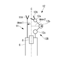
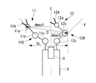
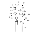
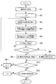
- FIG. 3B shows the arrangement of manipulators when it is assumed that the joint is moved to the target position in the slave device control method of FIG. 3A. It is a flowchart which shows the control method of the slave apparatus which concerns on the 1st Embodiment of this invention.
- FIG. 12A It is a schematic diagram of the front-end
- the manipulator system 1 includes a master device 2 that is operated by a doctor A, a slave device (manipulator device) 3 that is driven by input via the master device 2, and A controller 4 that controls the slave device 3 based on an input to the master device 2 and a monitor 5 are provided.
- the slave device 3 includes an elongated insertion portion 6 that can be inserted into the body of the patient P, and two pieces that are arranged in parallel to protrude from the distal end of the insertion portion 6.
- the slave device 3 outputs the endoscopic video acquired by the endoscope 8 to the monitor 5.
- the drive units 71 and 72 are provided in the controller 4, but may be provided separately from the controller 4.
- the manipulator 11 includes, in order from the distal end side, an end effector 11A and a joint portion 11B composed of a plurality of (three in this example) joints 11a, 11b, and 11c connected in series.
- the manipulator 12 includes an end effector 12A and a joint portion 12B including a plurality of (three in this example) joints 12a, 12b, and 12c connected in series with each other in order from the distal end side.
- the joints 11 a, 11 b, 11 c, 12 a, 12 b, 12 c are provided so as to be swingable about an axis perpendicular or parallel to the longitudinal direction of the insertion portion 6.
- the end effectors 11A and 12A are forceps, scissors, a needle holder, an electrode, a stapler, and the like for treating tissue.
- the number of joints of the manipulators 11 and 12 is not limited to three and can be changed as appropriate. Further, the number of joints of the manipulators 11 and 12 may be the same or different from each other.
- the master device 2 generates an operation signal corresponding to the operation performed by the doctor A, and transmits the generated operation signal to the controller 4.
- the controller 4 controls the drive units 71 and 72 based on the operation signal received from the master device 2, thereby causing the manipulators 11 and 12 to execute the operation corresponding to the operation signal, and the storage unit 10. I have.
- the manipulators 11 and 12 are operated from the arrangement shown in FIG. 3A to the arrangement shown in FIG. 3B. Will be described as an example.
- the joints 11a, 11b, The target positions 11c, 12a, 12b, and 12c are calculated using forward kinematics (position calculation step SA2). That is, the positions of the joints 11a, 11b, 11c, 12a, 12b, and 12c shown in FIG. 3B are calculated as target positions.
- position calculation step SA2 the dimension information of the manipulators 11 and 12 such as DH parameters stored in advance in the storage unit 10 and the current values of the joints 11a, 11b, 11c, 12a, 12b, and 12c detected by an encoder (not shown) are used.
- Position is used.
- the control unit 9 determines whether or not to move the joints 11a, 11b, 11c, 12a, 12b, and 12c to the target position according to the following procedure. . That is, first, the control unit 9 calculates the distance d from the central axis (reference line) C in the longitudinal direction of the insertion unit 6 to the target position of each joint 11a, 11b, 11c, 12a, 12b, 12c using the following formula (1 ) Based on (distance calculation step SA3).
- Equation (1) the coordinates of the target positions of the joints 11a, 11b, 11c, 12a, 12b, and 12c are defined as (x m , y m , z m ), and the positions (x m , y m , z m ) are defined. ) To the central axis C is defined as (x 0 , y 0 , z 0 ).
- the control unit 9 extracts the maximum value d max1 from the distances d calculated for the joints 11a, 11b, and 11c of the first manipulator 11, and the joints 12a, 12b, and 12c of the second manipulator 12 are extracted.
- the maximum value d max2 of the calculated distance d is extracted (distance calculation step SA4).
- the distance of the first joint 11 a at the most distal end of the first manipulator 11 and the distance of the second second joint 12 b from the distal end of the second manipulator 12 are extracted.
- the controller 9 calculates the maximum distance D by adding the two extracted maximum values d max1 and d max2 (distance calculation step SA5).
- This maximum distance D is the maximum distance that the manipulators 11 and 12 can take in a direction perpendicular to the longitudinal direction of the insertion portion 6 when the manipulators 11 and 12 are operated according to the operation signal.
- the control unit 9 compares the maximum distance D with a predetermined threshold Th (determination step SA6), and if the maximum distance D is equal to or less than the predetermined threshold Th (YES in step SA6), the joint 11a to the target position, By executing the movement of 11b, 11c, 12a, 12b, and 12c, the manipulators 11 and 12 are actually moved to the arrangement shown in FIG. 3B (movement execution step SA7). On the other hand, when the maximum distance D is greater than the predetermined threshold Th (NO in step SA6), the control unit 9 stops the movement of the joints 11a, 11b, 11c, 12a, 12b, and 12c to the target positions, The manipulators 11 and 12 are kept in the arrangement shown in FIG. 3A (movement stop step SA8).
- step SA6 whether or not the entire manipulators 11 and 12 are operable only within an allowable operation range that is a cylindrical space extending in the longitudinal direction of the insertion portion 6 with the predetermined threshold Th as a diameter. Is judged. If it is determined that the operation can be performed only within the allowable operation range, the manipulators 11 and 12 execute the operation based on the operation signal in step SA7, but the operations of the manipulators 11 and 12 are within the allowable operation range. When it is determined that the manipulators 11 and 12 extend outside, the operations of the manipulators 11 and 12 are stopped in step SA8.
- the predetermined threshold Th is determined in accordance with the size of the body cavity into which the manipulators 11 and 12 are inserted, the content of treatment, and the like. For example, when the manipulators 11 and 12 are inserted into a tubular body cavity such as the large intestine, the predetermined threshold Th is set equal to the diameter of the body cavity (specifically, 50 mm in the case of the large intestine). The When the manipulators 11 and 12 are inserted into a flat body cavity, the predetermined threshold Th is set equal to the thickness of the body cavity. For example, the doctor A selects and sets an appropriate value from values registered in advance in the controller 4 before the use of the slave device 3 by the doctor A.
- the insertion section 6 is introduced into the body cavity from the distal end, and the end effectors 11A and 12A are used as the affected area. Make them face each other. Thereafter, the doctor A can treat the affected area with the end effectors 11A and 12A by remotely operating the manipulators 11 and 12 using the master device 2.
- the joints 11a, 11b, 11c, 12a, 12b, and 12c From the target position to be moved (step SA2), the operation range of the manipulators 11 and 12 is estimated in advance (steps SA3 to SA5), and it is determined whether or not the operation range is within the allowable operation range (step SA6). ). If the operation range of the manipulators 11 and 12 is within the allowable operation range (YES in step SA6), the operation is executed by the manipulators 11 and 12 (step SA7). On the other hand, when the operation range of the manipulators 11 and 12 exceeds the allowable operation range (NO in step SA6), the execution of the operation is stopped (step SA8). Therefore, the operations of the manipulators 11 and 12 are limited within the allowable operation range.
- the target positions of the joints 11a, 11b, 11c, 12a, 12b, and 12c are used to operate the parts of the manipulators 11 and 12 after the operation.
- portions of the manipulators 11 and 12 that are located outside the field of view F of the endoscope 8 that is, portions that cannot be observed by the endoscope image
- the field of view F of the endoscope 8 that is, portions that cannot be observed by the endoscope image
- the allowable operation range of the manipulators 11 and 12 is maximized in the radial direction or the thickness direction of the body cavity up to its diameter when the body cavity is tubular, or up to its thickness when the body cavity is flat. There is an advantage that it can be secured to the limit.
- the manipulators 11 and 12 since the entire operation of the manipulators 11 and 12 is restricted within the diameter or thickness of the body cavity, the manipulators 11 and 12 do not come into strong contact with the surrounding tissue. Therefore, there is an advantage that the operability of the manipulators 11 and 12 can be maintained by preventing the operability of the manipulators 11 and 12 from being reduced by receiving force from the surrounding tissue.
- the two manipulators 11 and 12 are provided.
- the three manipulators 11, 12, and 13 may be provided.
- the control unit 9 extracts the maximum value d max3 of the distances d calculated for the joints 13a and 13b of the third manipulator 13, and obtains the three maximum values d max1 , d max2, may be obtained the two highest total as the maximum distance D of d max3.
- both manipulators 11 and 12 have joints 11a, 11b, 11c, 12a, 12b, and 12c.
- the distance between the first manipulator 11 and the central axis C is constant, and the maximum value d max1 is also constant. Therefore, in steps SA2 and SA3, only d max2 needs to be calculated for the joints 12a, 12b, and 12c of the second manipulator 12.
- FIGS. 7A to 9 a manipulator system 1 according to a second embodiment of the present invention will be described with reference to FIGS. 7A to 9.
- This embodiment is mainly different from the first embodiment in the method of controlling the slave device 3 by the control unit 9. Therefore, in this embodiment, this control content is mainly demonstrated, and about the structure which is common in 1st Embodiment, the same code
- the joints 11a and 12b having the maximum values d max1 and d max2 of the distance d are obtained.
- the distance D ′ between is used.
- the control unit 9 performs steps SB1 to SB3 in the same manner as steps SA1 to SA3 of the first embodiment. And the control part 9 specifies the farthest joint 11a from which the maximum value dmax1 of the distance d was obtained among the joints 11a, 11b, 11c of the manipulator 11, and among the joints 12a, 12b, 12c of the manipulator 12, The farthest joint 12b from which the maximum value d max2 of the distance d is obtained is specified (distance calculation step SB4). Next, the control unit 9 calculates the distance D ′ between the farthest joints 11a and 12b based on the following formula (2) (distance calculation step SB5).
- equation (2) the coordinates of the target position of the farthest joint of the first manipulator 11 are defined as (x 1 , y 1 , z 1 ), and the coordinates of the target position of the farthest joint of the second manipulator 12 are defined as It is defined as (x 2 , y 2 , z 2 ).
- This distance D ′ is the maximum distance among the distances between the joints 11a, 11b, and 11c of the first manipulator 11 and the joints 12a, 12b, and 12c of the second manipulator 12, and the manipulator 11 according to the operation signal.
- 12 corresponds to the maximum dimension that the manipulators 11, 12 can take in all directions with respect to the longitudinal direction of the insertion portion 6.
- the control unit 9 performs Steps SB6 to SB8 in the same manner as Steps SA6 to SA8 of the first embodiment except that the distance D ′ is used instead of the distance D.
- the insertion portion 6 is not necessarily arranged in parallel to the longitudinal direction or the flat direction of the body cavity in the body cavity. There is also a possibility of being arranged at an angle.
- the manipulators 11 and 12 are controlled so that the maximum distance D ′ of the manipulators 11 and 12 when considering not only the direction perpendicular to the longitudinal direction of the insertion portion 6 but also all directions is equal to or less than the threshold Th. Is done.
- step SB4 the control unit 9 specifies the farthest joint 13a from which the maximum distance value d max3 is obtained among the joints 13a and 13b of the third manipulator 13, and the three maximum obtained.
- the distance D ′ between the upper two joints 11b and 12a may be obtained.
- FIGS. 10 and 11 a manipulator system 1 according to a third embodiment of the present invention will be described with reference to FIGS. 10 and 11.
- the present embodiment is mainly different from the first and second embodiments in the method of controlling the slave device 3 by the control unit 9. Therefore, in the present embodiment, the contents of this control will be mainly described, and the same reference numerals are given to the configurations common to the first and second embodiments, and the description will be omitted.
- the slave device 3 includes three manipulators 11, 12, and 13, as shown in FIG. 10, and includes joints that have obtained the maximum values d max1 , d max2 , and d max3 of the distance d.
- the enclosed area S is used.
- the number of manipulators is not limited to three and may be four or more.
- the control unit 9 performs steps SC1 to SC4 in the same manner as steps SB1 to SB4 of the second embodiment.
- the control part 9 is the distance among the farthest joint 11b in which the maximum value dmax1 of the distance d is obtained among the joints 11a, 11b, and 11c of the manipulator 11, and the joints 12a, 12b, and 12c of the manipulator 12. and farthest joint 12a to the maximum value d max2 of d is obtained, the joint 13a of the manipulator 13, among 13b, top and far joint 13a to the maximum value d max3 is obtained of the distance d, to identify (area calculation step SC4).
- the control unit 9 calculates an area S of a triangle having the farthest joints 11b, 12a, and 13a as vertices in a plane orthogonal to the central axis C (area calculation step SC5).
- the area S is a direction perpendicular to the longitudinal direction of the insertion portion 6 that can be taken by a region surrounded by the manipulators 11, 12, 13 when the manipulators 11, 12 are operated according to the operation signal. This corresponds to the maximum area.
- control unit 9 uses the area S instead of the distance D, and uses the predetermined threshold Th ′ instead of the predetermined threshold Th, similarly to steps SA6 to SA8 of the first embodiment. Steps SC6 to SC8 are performed.
- the predetermined threshold Th ' is determined according to the size of the body cavity into which the manipulators 11, 12, and 13 are inserted and the content of treatment. This embodiment is used particularly when the manipulators 11, 12, and 13 are inserted into a tubular body cavity such as the large intestine, and the predetermined threshold Th 'is set to be equal to the cross-sectional area of the body cavity.
- the maximum area S in the direction perpendicular to the longitudinal direction of the insertion portion 6 in the region surrounded by the manipulators 11, 12, and 13 is predetermined.
- the manipulators 11 and 12 are controlled to be equal to or less than the threshold value Th ′. Since the cavity wall of a body cavity such as the large intestine has flexibility, as long as the maximum area S is less than or equal to the cross-sectional area of the body cavity, the cross-sectional shape can be changed according to the shape of the triangle. That is, according to the present embodiment, the manipulators 11, 12, and 13 are allowed to operate within a range in which the manipulators 11, 12, and 13 do not receive excessive force from the cavity wall. There is an advantage that strong contact with surrounding tissues can be prevented. Since the other effect of this embodiment is the same as 1st Embodiment, description is abbreviate
- FIGS. 12A to 13 a manipulator system 1 according to a fourth embodiment of the present invention will be described with reference to FIGS. 12A to 13.
- the manipulators 11, 12 arranged in an arbitrary arrangement are controlled when the manipulators 11, 12 are returned to a predetermined reference arrangement as shown in FIG. 12D.
- this control content is mainly demonstrated, and about the structure which is common in the 1st-3rd embodiment, the same code
- the control method of the slave device 3 of the present embodiment is used after the manipulators 11 and 12 are operated in an arbitrary arrangement by the control method described in the first to third embodiments, for example. It can be used in combination with the third embodiment.
- control unit 9 receives the return signal from the master device 2 (reception step SD1), and executes the return flow shown in FIG.
- the return signal is input to the master device 2 when the doctor A presses a return switch provided in the master device 2, for example.
- the reference positions of the joints 11a, 11b, 11c, 12a, 12b, and 12c for arranging the manipulators 11 and 12 in the reference arrangement are stored in the storage unit 10 in advance.
- the control unit 9 drives the joints 11a, 11b, 11c, 12a, 12b, and 12c in order from the third joints 11c and 12c on the proximal end side so as to coincide with the reference position.
- the control unit 9 calculates the arrangement of the manipulators 11 and 12 when it is assumed that the joint to be driven has moved to the reference position, and the movement of the joints based on the calculated arrangement of the manipulators 11 and 12. It is determined whether or not to execute.
- control unit 9 first selects the third joint 12c of one manipulator 12 (selection step SD2), and determines the maximum distance D when it is assumed that the third joint 12c has been moved to the reference position. Calculate (steps SD3 to SD6).
- 12A shows the current arrangement of the manipulators 11 and 12
- FIG. 12B shows the arrangement of the manipulators 11 and 12 when the third joint 12c is moved to the reference position.
- the procedures SD3 to SD6 for calculating the maximum distance D are the same as steps SA2 to SA5 described in the first embodiment.
- the controller 9 compares the maximum distance D with a predetermined threshold Th (determination step SD7). If the maximum distance D is equal to or less than the predetermined threshold Th (YES in step SD7), the control unit 9 moves the joint 12c to the target position. By executing the movement, the second manipulator 12 is actually moved to the arrangement shown in FIG. 12B (movement execution step SD8). On the other hand, when the maximum distance D is larger than the predetermined threshold Th (NO in step SD7), the control unit 9 stops the movement of the joint 12c to the target position, and the second manipulator 12 is shown in FIG. 12A. (The movement stop step SD9).
- Step SD11 Steps SD3 to SD9 are repeated. And when control of the 1st joint 12a is complete
- the control unit 9 performs the joint 11 a of the first manipulator 11. , 11b and 11c are similarly moved to the reference position, thereby finally returning the manipulators 11 and 12 to the reference arrangement shown in FIG. 12D.
- the doctor A can return the manipulators 11 and 12 arranged in an arbitrary position to a predetermined reference position by pressing the return switch during or after the treatment of the affected part.
- the return to the reference position is executed one by one from the third joints 11c and 12c on the proximal end side.
- the operation range of the manipulators 11 and 12 when the joint is moved is estimated in advance, and whether or not the operation range is within the allowable operation range. To be judged.
- the operation range of the manipulators 11 and 12 is within the allowable operation range, the movement of the joint is executed.
- the operation range of the manipulators 11 and 12 exceeds the allowable operation range, the movement of the joint is suspended and the drive target moves to the next joint.
- the held joint is executed after the return operation of the first joint to the reference position is completed.
- the manipulators 11 and 12 return to the reference arrangement while their operation ranges are limited within the allowable operation range.
- the allowable operation range of the manipulators 11 and 12 can be secured to the maximum in the radial direction or the thickness direction of the body cavity. is there. Moreover, there exists an advantage that return operation
- whether or not the joint can be moved is determined by the same method as in the first embodiment, but instead, the method described in the second embodiment may be employed. That is, steps SB4 to SB6 may be executed instead of steps SD5 to SD7. Further, when the three manipulators 11, 12, and 13 are provided, as described in the third embodiment, based on the area S of the triangle having the farthest joint of each manipulator 11, 12, and 13 as a vertex. Whether or not the joint can be moved may be determined.
- the joints 11a, 11b, 11c, 12a, 12b, 12c, 13a, 13b are determined when the maximum distances D, D ′ are determined to be larger than the predetermined threshold values Th, Th ′.
- the joints 11a, 11b, 11c, 12a, 12b, 12c, 13a, until the maximum distances D and D ′ become the predetermined threshold values Th and Th ′ are used. 13b may be moved, and further movement may be canceled.
- the predetermined threshold values Th and Th ′ are preferably smaller than the diameter or thickness of the body cavity.
- the controller 4 transmits a signal to the master device 2 to limit the operation input in the master device 2.
- the controller 4 transmits a signal to the master device 2 to limit the operation input in the master device 2.
- Manipulator system 2 Master device 3 Slave device (manipulator device) 4 Controller 5 Monitor 6 Insertion unit 8 Endoscope 9 Control unit 10 Storage unit 11, 12, 13 Manipulator 11A, 12A, 13A End effector 11B, 12B, 13B Joint unit 11a, 11b, 11c, 12a, 12b, 12c, 13a , 13b Joint 71, 72 Drive unit
Landscapes
- Health & Medical Sciences (AREA)
- Engineering & Computer Science (AREA)
- Life Sciences & Earth Sciences (AREA)
- Surgery (AREA)
- Robotics (AREA)
- Molecular Biology (AREA)
- Veterinary Medicine (AREA)
- Biomedical Technology (AREA)
- Heart & Thoracic Surgery (AREA)
- Medical Informatics (AREA)
- Nuclear Medicine, Radiotherapy & Molecular Imaging (AREA)
- Animal Behavior & Ethology (AREA)
- General Health & Medical Sciences (AREA)
- Public Health (AREA)
- Pathology (AREA)
- Physics & Mathematics (AREA)
- Biophysics (AREA)
- Optics & Photonics (AREA)
- Radiology & Medical Imaging (AREA)
- Mechanical Engineering (AREA)
- Signal Processing (AREA)
- Manipulator (AREA)
Abstract
マニピュレータ装置の制御方法は、マニピュレータに対する操作信号を受信するステップ(SA1)と、操作信号に基づいて関節の目標位置を計算するステップ(SA2)と、目標位置に関節を配置したと仮定したときの、マニピュレータ間の最大距離を計算するステップ(SA3,SA4,SA5)と、最大距離を所定の閾値と比較するステップ(SA6)と、最大距離が所定の閾値以下である場合に目標位置へ関節を移動させるステップ(SA7)と、最大距離が所定の閾値よりも大きい場合に関節の移動を中止するステップ(SA8)とを含む。
Description
本発明は、マニピュレータ装置の制御方法に関するものである。
従来、医療用のマニピュレータを内視鏡と一緒に体内に挿入し、内視鏡映像でマニピュレータを観察しながら該マニピュレータを遠隔操作する手術システムにおいて、マニピュレータの動作を許可する範囲を内視鏡の視野内に制限する技術が知られている(例えば、特許文献1参照。)。特許文献1によれば、医師は、マニピュレータの可動部分の全体を内視鏡映像で観察することができるので、マニピュレータが周囲の組織と衝突することがないようにマニピュレータを操作することができる。
しかしながら、特許文献1のように、マニピュレータの動作範囲を視野内に制限した場合、マニピュレータの可能な動作が限られてしまうため、使い勝手が悪くなるという問題がある。例えば、縫合作業のように、処置範囲を内視鏡で拡大観察しつつマニピュレータの大きな動作が必要となる処置には対応することが難しい。一方、もし、内視鏡の視野の外側でのマニピュレータの動作を許可した場合には、視野の外側でマニピュレータの一部分が周囲の組織と強く接触していたとしてもそのことに気付くことが難しいという問題がある。
本発明は、上述した事情に鑑みてなされたものであって、体内でのマニピュレータの許容動作範囲を最大限に確保しつつ、マニピュレータが周辺組織と強く接触することを防ぐことができるマニピュレータ装置の制御方法を提供することを目的とする。
上記目的を達成するため、本発明は以下の手段を提供する。
本発明の第1の態様は、互いに並列に配置された2以上のマニピュレータを備え、これらマニピュレータのうち少なくとも1つがその先端部に関節を有するマニピュレータ装置の制御方法であって、前記マニピュレータに対する操作信号を受信する受信ステップと、該受信ステップにおいて受信された操作信号に基づいて前記関節の移動すべき目標位置を計算する位置計算ステップと、該位置計算ステップにおいて算出された目標位置に前記関節を配置したと仮定したときの、前記マニピュレータ間の最大距離を計算する距離計算ステップと、該距離計算ステップにおいて算出された最大距離を所定の閾値と比較する判断ステップと、該判断ステップにおいて前記最大距離が前記所定の閾値以下であると判断された場合に、前記目標位置へ前記関節を移動させる移動実行ステップと、前記判断ステップにおいて前記最大距離が前記所定の閾値よりも大きいと判断された場合に、前記関節の移動を中止する移動中止ステップとを含むマニピュレータ装置の制御方法である。
本発明の第1の態様は、互いに並列に配置された2以上のマニピュレータを備え、これらマニピュレータのうち少なくとも1つがその先端部に関節を有するマニピュレータ装置の制御方法であって、前記マニピュレータに対する操作信号を受信する受信ステップと、該受信ステップにおいて受信された操作信号に基づいて前記関節の移動すべき目標位置を計算する位置計算ステップと、該位置計算ステップにおいて算出された目標位置に前記関節を配置したと仮定したときの、前記マニピュレータ間の最大距離を計算する距離計算ステップと、該距離計算ステップにおいて算出された最大距離を所定の閾値と比較する判断ステップと、該判断ステップにおいて前記最大距離が前記所定の閾値以下であると判断された場合に、前記目標位置へ前記関節を移動させる移動実行ステップと、前記判断ステップにおいて前記最大距離が前記所定の閾値よりも大きいと判断された場合に、前記関節の移動を中止する移動中止ステップとを含むマニピュレータ装置の制御方法である。
本発明の第1の態様によれば、受信ステップにおいて操作信号を受信すると、位置計算ステップにおいて、操作信号が示す関節の目標位置を計算し、移動実行ステップにおいて、目標位置に関節を移動させる。これにより、操作信号に応じた動作をマニピュレータに実行させることができる。
この場合に、移動実行ステップに先立って行われる距離計算ステップにおいて、目標位置に関節を移動させたときの各マニピュレータの配置を推定し、推定される配置におけるマニピュレータ間の最大距離を計算する。算出された最大距離は、マニピュレータを動作させたときのマニピュレータの並列方向の動作範囲の寸法に相当する。この最大距離を判断ステップにおいて所定の閾値と比較することによって、マニピュレータの動作範囲が、所定の閾値によって定義される寸法の許容動作範囲内に収まっているか否かを判定し、前記最大距離が所定の閾値よりも大きく、マニピュレータの動作範囲が許容動作範囲を超えることが推定された場合には、移動中止ステップによってマニピュレータの移動を中止する。
このように、各関節の目標位置を用いることによって、内視鏡等の観察装置の映像では視認できない部分についても許容動作範囲内に位置するか否かを判断することができる。したがって、許容動作範囲を、マニピュレータが配置される体腔の寸法にまで最大限に確保することができる。さらに、マニピュレータの動作範囲が許容動作範囲を超えると推定された場合にはマニピュレータの移動を中止することによって、マニピュレータが周辺組織と強く接触することを防ぐことができる。
上記第1の態様においては、前記距離計算ステップにおいて、前記2以上のマニピュレータの間を通りこれらマニピュレータに並列な基準線から各前記マニピュレータまでの距離の最大値を計算し、算出された最大値同士の合計を前記最大距離として計算してもよい。
このようにすることで、関節を有するマニピュレータについては、いずれかの関節が動作範囲の最も外側に配置され得るので、位置計算ステップにおいて算出した各関節の目標位置を有効に利用してマニピュレータ間の最大距離を簡単に求めることができる。
このようにすることで、関節を有するマニピュレータについては、いずれかの関節が動作範囲の最も外側に配置され得るので、位置計算ステップにおいて算出した各関節の目標位置を有効に利用してマニピュレータ間の最大距離を簡単に求めることができる。
上記第1の態様においては、前記2以上のマニピュレータの各々が、前記関節を有し、前記距離計算ステップにおいて、互いに異なる前記マニピュレータが有する前記関節間の距離の最大値を前記最大距離として計算してもよい。
このようにすることで、マニピュレータ同士の配列方向のみならずあらゆる方向を考慮したときのマニピュレータ間の最大距離が得られる。したがって、この最大距離が所定の閾値以下となるようにマニピュレータを制御することによって、周辺組織に対するマニピュレータの姿勢に依らずに、マニピュレータと周辺組織との接触をさらに確実に防ぐことができる。
このようにすることで、マニピュレータ同士の配列方向のみならずあらゆる方向を考慮したときのマニピュレータ間の最大距離が得られる。したがって、この最大距離が所定の閾値以下となるようにマニピュレータを制御することによって、周辺組織に対するマニピュレータの姿勢に依らずに、マニピュレータと周辺組織との接触をさらに確実に防ぐことができる。
本発明の第2の態様は、互いに並列に配置された3以上のマニピュレータを備え、これらマニピュレータのうち少なくとも1つが関節を有するマニピュレータ装置の制御方法であって、前記マニピュレータに対する操作信号を受信する受信ステップと、該受信ステップにおいて受信された操作信号に基づいて前記関節の移動すべき目標位置を計算する位置計算ステップと、該位置計算ステップにおいて算出された目標位置に前記関節を配置したと仮定したときの、前記3以上のマニピュレータを頂点とする多角形の最大面積を計算する面積計算ステップと、該面積計算ステップにおいて算出された最大面積を所定の閾値と比較する判断ステップと、該判断ステップにおいて前記最大面積が前記所定の閾値以下であると判断された場合に、前記目標位置へ前記関節を移動させる移動実行ステップと、前記判断ステップにおいて前記最大面積が前記所定の閾値よりも大きいと判断された場合に、前記関節の移動を中止する移動中止ステップとを含むマニピュレータ装置の制御方法である。
本発明の第2の態様によれば、移動実行ステップに先立って行われる面積計算ステップにおいて、目標位置に関節を移動させたときの各マニピュレータの配置を推定し、推定される配置においてマニピュレータに囲まれる、マニピュレータの配列方向の最大面積を計算する。算出された最大面積は、マニピュレータを動作させたときのマニピュレータの並列方向の作動範囲の面積に相当する。この最大面積を判断ステップにおいて所定の閾値と比較することによって、マニピュレータの動作範囲の面積が所定の閾値によって定義される断面積を有する許容動作範囲内であるか否かを判定し、前記最大面積が所定の閾値よりも大きい場合には、移動中止ステップによってマニピュレータの移動を中止する。
このようにすることで、許容動作範囲のマニピュータの並列方向の面積を、マニピュレータが配置される体腔の横断面積にまで最大限に確保することができる。さらに、マニピュレータの動作範囲が許容動作範囲を超えると推定された場合にはマニピュレータの移動を中止することによって、マニピュレータが周辺組織と強く接触することを防ぐことができる。
本発明の第3の態様は、互いに並列に配置された2以上のマニピュレータを備え、これらマニピュレータのうち少なくとも1つが少なくとも1つの関節を有するマニピュレータ装置の制御方法であって、前記関節の各々を所定の基準位置に移動させる復帰ステップを含み、該復帰ステップが、前記関節を択一的に選択する選択ステップと、該選択ステップにおいて選択された関節をその基準位置に配置したと仮定したときの、前記マニピュレータ間の最大距離を計算する距離計算ステップと、該距離計算ステップにおいて算出された最大距離を所定の閾値と比較する判断ステップと、該判断ステップにおいて前記最大距離が前記所定の閾値以下であると判断された場合に、前記選択ステップにおいて選択された関節を前記基準位置へ移動させる移動実行ステップと、前記判断ステップにおいて前記最大距離が前記所定の閾値よりも大きいと判断された場合に、前記選択ステップにおいて選択された関節の移動を中止する移動中止ステップと、前記選択ステップにおいて選択する関節を切り替えて前記距離計算ステップと、前記判断ステップと、前記移動実行ステップまたは前記移動中止ステップとを繰り返す繰り返しステップとを含むマニピュレータ装置の制御方法である。
本発明の第3の態様によれば、復帰ステップにおいて、選択ステップにおいて選択された1つの関節を移動実行ステップにおいて基準位置へ移動させる作業を繰り返しステップにおいて関節を切り替えながら繰り返し、関節を1つずつ順番に基準位置へ移動させることにより、任意の配置のマニピュレータを所定の基準配置へ復帰することができる。
この場合に、移動実行ステップに先立って行われる距離計算ステップにおいて、目標位置に関節を移動させたときのマニピュレータの配置を推定し、推定される配置におけるマニピュレータ間の最大距離を計算する。そして、この最大距離を判断ステップにおいて所定の閾値と比較し、前記最大距離が所定の閾値よりも大きい場合には、移動中止ステップによって当該関節の移動を中止する。
このようにすることで、許容動作範囲をマニピュレータが配置される体腔の寸法にまで最大限に確保することができ、さらに、マニピュレータが周辺組織と強く接触することを防ぐことができる。
このようにすることで、許容動作範囲をマニピュレータが配置される体腔の寸法にまで最大限に確保することができ、さらに、マニピュレータが周辺組織と強く接触することを防ぐことができる。
本発明によれば、体内でのマニピュレータの許容動作範囲を最大限に確保しつつ、マニピュレータが周辺組織と強く接触することを防ぐことができるという効果を奏する。
(第1の実施形態)
本発明の第1の実施形態に係るマニピュレータシステム1とその制御方法について図1から図6を参照して以下に説明する。
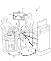
本実施形態に係るマニピュレータシステム1は、図1に示されるように、医師Aにより操作されるマスタ装置2と、該マスタ装置2を介した入力によって駆動されるスレーブ装置(マニピュレータ装置)3と、マスタ装置2への入力に基づいてスレーブ装置3を制御するコントローラ4と、モニタ5とを備えている。
本発明の第1の実施形態に係るマニピュレータシステム1とその制御方法について図1から図6を参照して以下に説明する。
本実施形態に係るマニピュレータシステム1は、図1に示されるように、医師Aにより操作されるマスタ装置2と、該マスタ装置2を介した入力によって駆動されるスレーブ装置(マニピュレータ装置)3と、マスタ装置2への入力に基づいてスレーブ装置3を制御するコントローラ4と、モニタ5とを備えている。
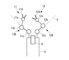
スレーブ装置3は、図2、図3Aおよび図3Bに示されるように、患者Pの体内に挿入可能な細長い挿入部6と、該挿入部6の先端から突出して互いに並列に配置された2本の多関節のマニピュレータ11,12と、該マニピュレータ11,12を駆動する駆動部71,72と、マニピュレータ11,12を撮影する内視鏡8とを備える。スレーブ装置3は、内視鏡8によって取得した内視鏡映像をモニタ5に出力する。図2において、駆動部71,72は、コントローラ4内に設けられているが、コントローラ4とは別々に設けられていてもよい。
マニピュレータ11は、先端側から順に、エンドエフェクタ11Aと、互いに直列に連結された複数の(本例においては3個の)関節11a,11b,11cからなる関節部11Bとを有している。同様に、マニピュレータ12は、先端側から順に、エンドエフェクタ12Aと、互いに直列に連結された複数の(本例においては3個の)関節12a,12b,12cからなる関節部12Bとを有している。関節11a,11b,11c,12a,12b,12cは、挿入部6の長手方向に対して垂直または平行な軸回りに揺動可能に設けられている。各関節11a,11b,11c,12a,12b,12cが駆動部71,72によって駆動されることによって、マニピュレータ11,12の位置および形状が変更され、エンドエフェクタ11A,12Aの位置および姿勢が変更されるようになっている。エンドエフェクタ11A,12Aは、組織を処置するための鉗子やハサミ、持針器、電極、ステープラ等である。
マニピュレータ11,12の関節の数は、3個に限定されるものではなく、適宜変更可能である。また、マニピュレータ11,12の関節の数は、互いに同一であってもよく、互いに異なっていてもよい。
マスタ装置2は、医師Aによってなされた操作に対応する操作信号を生成し、生成した操作信号をコントローラ4に送信する。
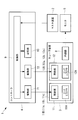
コントローラ4は、マスタ装置2から受信した操作信号に基づいて駆動部71,72を制御し、それによって操作信号に対応する動作をマニピュレータ11,12に実行させる制御部9と、記憶部10とを備えている。
コントローラ4は、マスタ装置2から受信した操作信号に基づいて駆動部71,72を制御し、それによって操作信号に対応する動作をマニピュレータ11,12に実行させる制御部9と、記憶部10とを備えている。
次に、本発明に係るマニピュレータ装置の制御方法に対応する、制御部9によるスレーブ装置3の制御方法について、図3Aに示される配置から図3Bに示される配置へマニピュレータ11,12を動作させる場合を例に挙げて説明する。
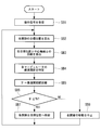
図4に示されるように、制御部9は、マスタ装置2から操作信号を受信すると(受信ステップSA1)、この操作信号が示す配置にマニピュレータ11,12を配するための各関節11a,11b,11c,12a,12b,12cの目標位置を、順運動学を用いて計算する(位置計算ステップSA2)。つまり、図3Bに示されている各関節11a,11b,11c,12a,12b,12cの位置が目標位置として計算される。この計算には、記憶部10に予め記憶されているDHパラメータ等のマニピュレータ11,12の寸法情報や、図示しないエンコーダによって検出された各関節11a,11b,11c,12a,12b,12cの現在の位置が用いられる。
次に、制御部9は、算出された目標位置に基づき、当該目標位置への各関節11a,11b,11c,12a,12b,12cの移動を実行するか否かを、以下の手順によって判断する。
すなわち、まず、制御部9は、挿入部6の長手方向の中心軸線(基準線)Cから各関節11a,11b,11c,12a,12b,12cの目標位置までの距離dを、下式(1)に基づいて計算する(距離計算ステップSA3)。式(1)において、各関節11a,11b,11c,12a,12b,12cの目標位置の座標を(xm,ym,zm)と定義し、各位置(xm,ym,zm)から中心軸線Cにおろした垂線の足の座標を(x0,y0,z0)と定義している。
すなわち、まず、制御部9は、挿入部6の長手方向の中心軸線(基準線)Cから各関節11a,11b,11c,12a,12b,12cの目標位置までの距離dを、下式(1)に基づいて計算する(距離計算ステップSA3)。式(1)において、各関節11a,11b,11c,12a,12b,12cの目標位置の座標を(xm,ym,zm)と定義し、各位置(xm,ym,zm)から中心軸線Cにおろした垂線の足の座標を(x0,y0,z0)と定義している。

次に、制御部9は、第1のマニピュレータ11の関節11a,11b,11cについて算出された距離dのうちの最大値dmax1を抽出し、第2のマニピュレータ12の関節12a,12b,12cについて算出された距離dのうちの最大値dmax2を抽出する(距離計算ステップSA4)。図3Bにおいては、第1のマニピュレータ11の最も先端の第1関節11aの距離と、第2のマニピュレータ12の先端から2番目の第2関節12bの距離とが抽出される。
次に、制御部9は、抽出された2つの最大値dmax1,dmax2を足し合わせて最大距離Dを計算する(距離計算ステップSA5)。この最大距離Dは、操作信号に従ってマニピュレータ11,12を動作させたときにマニピュレータ11,12が挿入部6の長手方向に垂直な方向に取り得る、最大距離である。
制御部9は、最大距離Dを所定の閾値Thと比較し(判断ステップSA6)、最大距離Dが所定の閾値Th以下である場合には(ステップSA6のYES)、目標位置への関節11a,11b,11c,12a,12b,12cの移動を実行することによって、図3Bに示される配置へマニピュレータ11,12を実際に動作させる(移動実行ステップSA7)。一方、最大距離Dが所定の閾値Thよりも大きい場合には(ステップSA6のNO)、制御部9は、目標位置への関節11a,11b,11c,12a,12b,12cの移動を中止し、マニピュレータ11,12を図3Aに示される配置にとどめる(移動中止ステップSA8)。
すなわち、ステップSA6においては、マニピュレータ11,12の全体が、所定の閾値Thを直径とし、挿入部6の長手方向に延びる円柱状の空間である許容動作範囲内のみで動作可能であるか否かが判断される。そして、許容動作範囲内のみでの動作が可能であると判断された場合には、ステップSA7においてマニピュレータ11,12が操作信号に基づく動作を実行するが、マニピュレータ11,12の動作が許容動作範囲の外側にまで及ぶと判断された場合には、ステップSA8においてマニピュレータ11,12の動作が中止される。
ここで、所定の閾値Thは、マニピュレータ11,12が挿入される体腔の寸法や処置内容等に応じて決定される。例えば、マニピュレータ11,12が大腸のような管状の体腔内に挿入される場合には、所定の閾値Thは、体腔の直径と同等(具体的には、大腸の場合には50mm)に設定される。また、マニピュレータ11,12が平坦状の体腔内に挿入される場合には、所定の閾値Thは、体腔の厚さと同等に設定される。この閾値Thは、例えば、医師Aが、スレーブ装置3の使用前に、コントローラ4に予め登録された値の中から適切なものを選択して設定するようになっている。
次に、このように構成されたマニピュレータシステム1の作用について説明する。
本実施形態に係るマニピュレータシステム1を用いて、患者Pの体腔内に存在する患部の処置を行うには、挿入部6を先端から体腔内に導入していき、エンドエフェクタ11A,12Aを患部に対向させる。この後、医師Aは、マスタ装置2を用いてマニピュレータ11,12を遠隔操作することによって、エンドエフェクタ11A,12Aにより患部を処置することができる。
本実施形態に係るマニピュレータシステム1を用いて、患者Pの体腔内に存在する患部の処置を行うには、挿入部6を先端から体腔内に導入していき、エンドエフェクタ11A,12Aを患部に対向させる。この後、医師Aは、マスタ装置2を用いてマニピュレータ11,12を遠隔操作することによって、エンドエフェクタ11A,12Aにより患部を処置することができる。
このときに、マニピュレータシステム1においては、医師Aによってマスタ装置2に入力された操作に対応する動作をマニピュレータ11,12に実行させる前に、各関節11a,11b,11c,12a,12b,12cの移動すべき目標位置から(ステップSA2)、マニピュレータ11,12の動作範囲が事前に推定され(ステップSA3からSA5)、その動作範囲が許容動作範囲内であるか否かが判断される(ステップSA6)。そして、マニピュレータ11,12の動作範囲が許容動作範囲内である場合には(ステップSA6のYES)、その動作がマニピュレータ11,12によって実行される(ステップSA7)。一方、マニピュレータ11,12の動作範囲が許容動作範囲を超える場合には(ステップSA6のNO)、その動作の実行が中止される(ステップSA8)。したがって、マニピュレータ11,12の動作は、許容動作範囲内に制限される。
この場合に、本実施形態に係るマニピュレータシステム1とその制御方法によれば、各関節11a,11b,11c,12a,12b,12cの目標位置を用いてマニピュレータ11,12の各部分の動作後の位置を推定することによって、マニピュレータ11,12の、内視鏡8の視野Fの外側に位置する部分(すなわち、内視鏡映像によって観察できない部分)についても、内視鏡8の視野F内であるか否かに関わらず、許容動作範囲内であるか否かを判断して適切に制御することが可能となる。したがって、マニピュレータ11,12の許容動作範囲を、体腔が管状である場合にはその径寸法まで、体腔が平坦状である場合にはその厚さ寸法まで、体腔の径方向または厚さ方向に最大限に確保することができるという利点がある。
さらに、マニピュレータ11,12全体の動作が、体腔の径寸法内または厚さ寸法内に制限されるので、マニピュレータ11,12が周辺組織と強く接触することがない。したがって、マニピュレータ11,12が周辺組織から力を受けることによってその操作性が低下してしまうことを防止して、マニピュレータ11,12の操作性を維持することができるという利点がある。
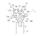
本実施形態においては、2本のマニピュレータ11,12を備えることとしたが、これに代えて、図5Aおよび図5Bに示されるように、3本のマニピュレータ11,12,13を備えることとしてもよい。
この場合、制御部9は、ステップSA4において、第3のマニピュレータ13が有する関節13a,13bについて算出された距離dのうちの最大値dmax3を抽出し、得られた3つの最大値dmax1,dmax2,dmax3のうち上位2つの合計を最大距離Dとして求めればよい。
この場合、制御部9は、ステップSA4において、第3のマニピュレータ13が有する関節13a,13bについて算出された距離dのうちの最大値dmax3を抽出し、得られた3つの最大値dmax1,dmax2,dmax3のうち上位2つの合計を最大距離Dとして求めればよい。
本実施形態においては、両方のマニピュレータ11,12が関節11a,11b,11c,12a,12b,12cを有することとしたが、これに代えて、図6に示されるように、一方のマニピュレータ11,12は関節を有さなくてもよい。例えば、第1のマニピュレータ11が関節を有さない場合、この第1のマニピュレータ11と中心軸線Cとの距離は一定となり、最大値dmax1も一定となる。したがって、ステップSA2,SA3においては、第2のマニピュレータ12の関節12a,12b,12cについてdmax2のみ計算を行えばよい。
(第2の実施形態)
次に、本発明の第2の実施形態に係るマニピュレータシステム1について図7Aから図9を参照して説明する。
本実施形態は、制御部9によるスレーブ装置3の制御方法において第1の実施形態と主に異なっている。したがって、本実施形態においてはこの制御内容について主に説明し、第1の実施形態と共通する構成については同一の符号を付して説明を省略する。
次に、本発明の第2の実施形態に係るマニピュレータシステム1について図7Aから図9を参照して説明する。
本実施形態は、制御部9によるスレーブ装置3の制御方法において第1の実施形態と主に異なっている。したがって、本実施形態においてはこの制御内容について主に説明し、第1の実施形態と共通する構成については同一の符号を付して説明を省略する。
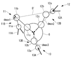
本実施形態においては、マニピュレータ11,12の動作の可否を判断する基準として、図7Aおよび図7Bに示されるように、距離dの最大値dmax1,dmax2が得られた関節11a,12b同士の間の距離D’を用いる。
具体的には、図8に示されるように、制御部9は、第1の実施形態のステップSA1からSA3と同様に、ステップSB1からSB3を行う。そして、制御部9は、マニピュレータ11の関節11a,11b,11cのうち、距離dの最大値dmax1が得られた最遠関節11aを特定し、マニピュレータ12の関節12a,12b,12cのうち、距離dの最大値dmax2が得られた最遠関節12bを特定する(距離計算ステップSB4)。次に、制御部9は、最遠関節11a,12b間の距離D’を下式(2)に基づいて計算する(距離計算ステップSB5)。式(2)において、第1のマニピュレータ11の最遠関節の目標位置の座標を(x1,y1,z1)と定義し、第2のマニピュレータ12の最遠関節の目標位置の座標を(x2,y2,z2)と定義している。

この距離D’は、第1のマニピュレータ11の関節11a,11b,11cと、第2のマニピュレータ12の関節12a,12b,12cとの間の距離のうちの最大距離であり、操作信号に従ってマニピュレータ11,12を動作させたときにマニピュレータ11,12が挿入部6の長手方向に対してあらゆる方向に取り得る、最大寸法に相当する。
以下、制御部9は、距離Dに代えて距離D’を用いる点を除いて、第1の実施形態のステップSA6からSA8と同様に、ステップSB6からSB8を行う。
以下、制御部9は、距離Dに代えて距離D’を用いる点を除いて、第1の実施形態のステップSA6からSA8と同様に、ステップSB6からSB8を行う。
このように構成された本実施形態に係るマニピュレータシステム1およびその制御方法によれば、体腔内において挿入部6は体腔の長手方向または平坦方向に対して必ずしも平行に配置されるとは限らず、斜めに配置される可能性もある。本実施形態においては、挿入部6の長手方向に垂直な方向のみならずあらゆる方向を考慮したときのマニピュレータ11,12の最大距離D’が閾値Th以下となるように、マニピュレータ11,12が制御される。
これにより、体腔内においてマニピュレータ11,12がどのような姿勢に配置されたとしても、マニピュレータ11,12全体の動作が、体腔の径寸法内または厚さ寸法内に制限されるので、マニピュレータ11,12が周辺組織と強く接触することをさらに確実に防止することができるという利点がある。
本実施形態のその他の作用効果は、第1の実施形態と同じであるので説明を省略する。
本実施形態のその他の作用効果は、第1の実施形態と同じであるので説明を省略する。
本実施形態においても、図9に示されるように、3本のマニピュレータ11,12,13を備えることとしてもよい。
この場合、制御部9は、ステップSB4において、第3のマニピュレータ13が有する関節13a,13bのうち、距離の最大値dmax3が得られた最遠関節13aを特定し、得られた3つの最大値dmax1,dmax2,dmax3のうち上位2つの関節11b,12a間の距離D’を求めればよい。
この場合、制御部9は、ステップSB4において、第3のマニピュレータ13が有する関節13a,13bのうち、距離の最大値dmax3が得られた最遠関節13aを特定し、得られた3つの最大値dmax1,dmax2,dmax3のうち上位2つの関節11b,12a間の距離D’を求めればよい。
(第3の実施形態)
次に、本発明の第3の実施形態に係るマニピュレータシステム1について図10および図11を参照して説明する。
本実施形態は、制御部9によるスレーブ装置3の制御方法において第1および第2の実施形態と主に異なっている。したがって、本実施形態においてはこの制御内容について主に説明し、第1および第2の実施形態と共通する構成については同一の符号を付して説明を省略する。
次に、本発明の第3の実施形態に係るマニピュレータシステム1について図10および図11を参照して説明する。
本実施形態は、制御部9によるスレーブ装置3の制御方法において第1および第2の実施形態と主に異なっている。したがって、本実施形態においてはこの制御内容について主に説明し、第1および第2の実施形態と共通する構成については同一の符号を付して説明を省略する。
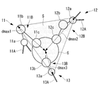
本実施形態において、スレーブ装置3は、図10に示されるように、3本のマニピュレータ11,12,13を備え、距離dの最大値dmax1,dmax2,dmax3が得られた関節同士によって囲まれる面積Sを用いる。マニピュレータの数は、3本に限定されるものではなく、4本以上であってもよい。
具体的には、図11に示されるように、制御部9は、第2の実施形態のステップSB1からSB4と同様に、ステップSC1からSC4を行う。これにより、制御部9は、マニピュレータ11の関節11a,11b,11cのうち、距離dの最大値dmax1が得られた最遠関節11bと、マニピュレータ12の関節12a,12b,12cのうち、距離dの最大値dmax2が得られた最遠関節12aと、マニピュレータ13の関節13a,13bのうち、距離dの最大値dmax3が得られた最遠関節13aと、を特定する(面積計算ステップSC4)。次に、制御部9は、中心軸線Cに直交する平面において、最遠関節11b,12a,13aを頂点とする三角形の面積Sを計算する(面積計算ステップSC5)。この面積Sは、図10に示されるように、操作信号に従ってマニピュレータ11,12を動作させたときにマニピュレータ11,12,13によって囲まれる領域が取り得る、挿入部6の長手方向に垂直な方向の最大面積に相当する。
この後、制御部9は、距離Dに代えて面積Sを用い、所定の閾値Thに代えて所定の閾値Th’を用いる点を除いて、第1の実施形態のステップSA6からSA8と同様に、ステップSC6からSC8を行う。所定の閾値Th’は、マニピュレータ11,12,13が挿入される体腔の寸法や処置内容に応じて決定される。本実施形態は、特に大腸のような管状の体腔内にマニピュレータ11,12,13を挿入する場合に用いられ、所定の閾値Th’は、体腔の横断面積と同等に設定される。
このように構成された本実施形態に係るマニピュレータシステム1およびその制御方法によれば、マニピュレータ11,12,13によって囲まれる領域の、挿入部6の長手方向に垂直な方向の最大面積Sが所定の閾値Th’以下となるように、マニピュレータ11,12が制御される。大腸のような体腔の腔壁は柔軟性を有するため、最大面積Sが体腔の横断面積以下でありさえすれば、上記三角形の形状に合わせてその横断面形状を変化させることができる。すなわち、本実施形態によれば、マニピュレータ11,12,13が腔壁から過剰な力を受けずに済む範囲でマニピュレータ11,12,13の動作が許可されるので、マニピュレータ11,12,13が周辺組織と強く接触することを防止することができるという利点がある。
本実施形態のその他の作用効果は、第1の実施形態と同じであるので説明を省略する。
本実施形態のその他の作用効果は、第1の実施形態と同じであるので説明を省略する。
(第4の実施形態)
次に、本発明の第4の実施形態に係るマニピュレータシステム1について図12Aから図13を参照して説明する。
本実施形態は、図12Aに示されるように、任意の配置に配されているマニピュレータ11,12を、図12Dに示されるように、所定の基準配置に復帰させるときのマニピュレータ11,12の制御方法に関する。したがって、本実施形態においてはこの制御内容について主に説明し、第1から第3の実施形態と共通する構成については同一の符号を付して説明を省略する。
次に、本発明の第4の実施形態に係るマニピュレータシステム1について図12Aから図13を参照して説明する。
本実施形態は、図12Aに示されるように、任意の配置に配されているマニピュレータ11,12を、図12Dに示されるように、所定の基準配置に復帰させるときのマニピュレータ11,12の制御方法に関する。したがって、本実施形態においてはこの制御内容について主に説明し、第1から第3の実施形態と共通する構成については同一の符号を付して説明を省略する。
本実施形態のスレーブ装置3の制御方法は、例えば第1から第3の実施形態で説明した制御方法でマニピュレータ11,12を任意の配置に動作させた後に用いられるものであり、第1から第3の実施形態と組み合わせて用いることができる。
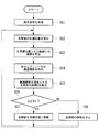
本実施形態において、制御部9は、マスタ装置2から復帰信号を受信することによって(受信ステップSD1)、図13に示される復帰フローを実行する。復帰信号は、例えば、マスタ装置2に設けられた復帰スイッチを医師Aが押下することによってマスタ装置2に入力されるようになっている。
マニピュレータ11,12を基準配置に配するための各関節11a,11b,11c,12a,12b,12cの基準位置は、予め記憶部10に記憶されている。制御部9は、基端側の第3関節11c,12cから順番に、基準位置に一致させるように関節11a,11b,11c,12a,12b,12cを駆動させる。このときに、制御部9は、駆動対象の関節が基準位置へ移動したと仮定したときのマニピュレータ11,12の配置を計算し、算出されたマニピュレータ11,12の配置に基づいて当該関節の移動を実行するか否かを判断する。
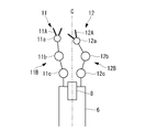
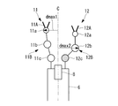
具体的には、制御部9は、まず、一方のマニピュレータ12の第3関節12cを選択し(選択ステップSD2)、該第3関節12cを基準位置まで移動させたと仮定したときの最大距離Dを算出する(ステップSD3からSD6)。図12Aが現在のマニピュレータ11,12の配置、図12Bが第3関節12cを基準位置に移動させたときのマニピュレータ11,12の配置を示している。最大距離Dの計算の手順SD3からSD6は、第1の実施形態において説明したステップSA2からSA5と同様である。
制御部9は、最大距離Dを所定の閾値Thと比較し(判断ステップSD7)、最大距離Dが所定の閾値Th以下である場合には(ステップSD7のYES)、目標位置への関節12cの移動を実行することによって、図12Bに示される配置へ第2のマニピュレータ12を実際に動作させる(移動実行ステップSD8)。一方、最大距離Dが所定の閾値Thよりも大きい場合には(ステップSD7のNO)、制御部9は、目標位置への関節12cの移動を中止し、第2のマニピュレータ12を図12Aに示される配置にとどめる(移動中止ステップSD9)。
次に、制御部9は、図12Cに示されるように、駆動対象を第2関節12bに切り替えて(繰り返しステップSD11)ステップSD3からSD9を繰り返し、さらに、駆動対象を第1関節12aに切り替えて(ステップSD11)ステップSD3からSD9を繰り返す。そして、第1関節12aの制御が終了した時点で(ステップSD10のYES)、もし、基準位置に配置されていない関節が残っている場合には(ステップSD12のNO)、制御部9は、再び第3関節12cから順番に(ステップSD13)、ステップSD3からSD9に従って基準位置への復帰動作を繰り返す。
さらに、図13には示されていないが、第2のマニピュレータ12の全ての関節12a,12b,12cの基準位置への移動が完了した後、制御部9は、第1のマニピュレータ11の関節11a,11b,11cも同様に基準位置へ移動させることによって、最終的に図12Dに示される基準配置へマニピュレータ11,12を復帰させる。
次に、このように構成されたマニピュレータシステム1の作用について説明する。
医師Aは、患部の処置の途中や終了後に、復帰スイッチを押下することによって、任意の配置に配されたマニピュレータ11,12を所定の基準位置へ復帰させることができる。
医師Aは、患部の処置の途中や終了後に、復帰スイッチを押下することによって、任意の配置に配されたマニピュレータ11,12を所定の基準位置へ復帰させることができる。
このときに、マニピュレータシステム1においては、基端側の第3関節11c,12cから順番に1つずつ基準位置への復帰が実行される。ただし、駆動対象の関節を基準位置へ移動させる前に、当該関節が移動させたときのマニピュレータ11,12の動作範囲が事前に推定され、その動作範囲が許容動作範囲内であるか否かが判断される。そして、マニピュレータ11,12の動作範囲が許容動作範囲内である場合には、その関節の移動が実行される。一方、マニピュレータ11,12の動作範囲が許容動作範囲を超える場合には、その関節の移動は保留されて、駆動対象は次の関節へ移行する。保留された関節については、第1関節の基準位置への復帰動作が終了した後に、実行される。以上により、マニピュレータ11,12は、その動作範囲が許容動作範囲内に制限されながら、基準配置へ復帰する。
このように、本実施形態に係るマニピュレータシステム1とその制御方法によれば、マニピュレータ11,12の許容動作範囲を、体腔の径方向または厚さ方向に最大限に確保することができるという利点がある。また、マニピュレータ11,12が周辺組織と強く接触することがないように復帰動作を実行することができるという利点がある。
本実施形態においては、第1の実施形態と同様の方法で関節の移動の可否を判断することとしたが、これに代えて、第2の実施形態で説明した方法を採用してもよい。すなわち、ステップSD5からSD7に代えて、ステップSB4からSB6を実行してもよい。
また、3本のマニピュレータ11,12,13を備える場合には、第3の実施形態で説明したように、各マニピュレータ11,12,13の最遠関節を頂点とする三角形の面積Sに基づいて、関節の移動の可否を判断してもよい。
また、3本のマニピュレータ11,12,13を備える場合には、第3の実施形態で説明したように、各マニピュレータ11,12,13の最遠関節を頂点とする三角形の面積Sに基づいて、関節の移動の可否を判断してもよい。
なお、上記の各実施形態においては、最大距離D,D’が所定の閾値Th,Th’よりも大きいと判断された場合に、関節11a,11b,11c,12a,12b,12c,13a,13bの移動を中止とすることとしたが、これに代えて、最大距離D,D’が所定の閾値Th,Th’となる位置までは関節11a,11b,11c,12a,12b,12c,13a,13bを移動させ、それ以上の移動については中止することしてもよい。この場合、所定の閾値Th,Th’は、体腔の直径または厚さよりも小さいことが好ましい。
加えて、最大距離D,D’が所定の閾値Th,Th’となる位置へ関節11a,11b,11c,12a,12b,12c,13a,13bが移動した時点で、医師A(操作者)に対して音等の警告を出力することによって、それ以上関節11a,11b,11c,12a,12b,12c,13a,13bを移動させた場合には最大距離D,D’が所定の閾値Th,Th’よりも大きくなることを術者Aに認識させてもよい。
さらに、最大距離D,D’が所定の閾値Th,Th’よりも大きいと判断された場合に、コントローラ4が、マスタ装置2へ信号を送信して該マスタ装置2での操作入力を制限することによって、最大距離D,D’が所定の閾値Th,Th’よりも大きくなることがないように、関節11a,11b,11c,12a,12b,12c,13a,13bの移動を中止してもよい。
1 マニピュレータシステム
2 マスタ装置
3 スレーブ装置(マニピュレータ装置)
4 コントローラ
5 モニタ
6 挿入部
8 内視鏡
9 制御部
10 記憶部
11,12,13 マニピュレータ
11A,12A,13A エンドエフェクタ
11B,12B,13B 関節部
11a,11b,11c,12a,12b,12c,13a,13b 関節
71,72 駆動部
A 医師
P 患者
F 内視鏡の視野
SA1,SB1,SC1,SD1 受信ステップ
SA2,SB2,SC2,SD3 位置計算ステップ
SA3,SA4,SA5,SB3,SB4,SB5,SD4,SD5,SD6 距離計算ステップ
SA6,SB6,SC6,SD7 判断ステップ
SA7,SB7,SC7,SD8 移動実行ステップ
SA8,SB8,SC8,SD9 移動中止ステップ
SC4,SC5 面積計算ステップ
SD2 選択ステップ
SD11 繰り返しステップ
2 マスタ装置
3 スレーブ装置(マニピュレータ装置)
4 コントローラ
5 モニタ
6 挿入部
8 内視鏡
9 制御部
10 記憶部
11,12,13 マニピュレータ
11A,12A,13A エンドエフェクタ
11B,12B,13B 関節部
11a,11b,11c,12a,12b,12c,13a,13b 関節
71,72 駆動部
A 医師
P 患者
F 内視鏡の視野
SA1,SB1,SC1,SD1 受信ステップ
SA2,SB2,SC2,SD3 位置計算ステップ
SA3,SA4,SA5,SB3,SB4,SB5,SD4,SD5,SD6 距離計算ステップ
SA6,SB6,SC6,SD7 判断ステップ
SA7,SB7,SC7,SD8 移動実行ステップ
SA8,SB8,SC8,SD9 移動中止ステップ
SC4,SC5 面積計算ステップ
SD2 選択ステップ
SD11 繰り返しステップ
Claims (5)
- 互いに並列に配置された2以上のマニピュレータを備え、これらマニピュレータのうち少なくとも1つが関節を有するマニピュレータ装置の制御方法であって、
前記マニピュレータに対する操作信号を受信する受信ステップと、
該受信ステップにおいて受信された操作信号に基づいて前記関節の移動すべき目標位置を計算する位置計算ステップと、
該位置計算ステップにおいて算出された目標位置に前記関節を配置したと仮定したときの、前記マニピュレータ間の最大距離を計算する距離計算ステップと、
該距離計算ステップにおいて算出された最大距離を所定の閾値と比較する判断ステップと、
該判断ステップにおいて前記最大距離が前記所定の閾値以下であると判断された場合に、前記目標位置へ前記関節を移動させる移動実行ステップと、
前記判断ステップにおいて前記最大距離が前記所定の閾値よりも大きいと判断された場合に、前記関節の移動を中止する移動中止ステップとを含むマニピュレータ装置の制御方法。 - 前記距離計算ステップにおいて、前記2以上のマニピュレータの間を通りこれらマニピュレータに並列な基準線から各前記マニピュレータまでの距離の最大値を計算し、算出された最大値同士の合計を前記最大距離として計算する請求項1に記載のマニピュレータ装置の制御方法。
- 前記2以上のマニピュレータの各々が、前記関節を有し、
前記距離計算ステップにおいて、互いに異なる前記マニピュレータが有する前記関節間の距離の最大値を前記最大距離として計算する請求項1に記載のマニピュレータ装置の制御方法。 - 互いに並列に配置された3以上のマニピュレータを備え、これらマニピュレータのうち少なくとも1つが関節を有するマニピュレータ装置の制御方法であって、
前記マニピュレータに対する操作信号を受信する受信ステップと、
該受信ステップにおいて受信された操作信号に基づいて前記関節の移動すべき目標位置を計算する位置計算ステップと、
該位置計算ステップにおいて算出された目標位置に前記関節を配置したと仮定したときの、前記3以上のマニピュレータを頂点とする多角形の最大面積を計算する面積計算ステップと、
該面積計算ステップにおいて算出された最大面積を所定の閾値と比較する判断ステップと、
該判断ステップにおいて前記最大面積が前記所定の閾値以下であると判断された場合に、前記目標位置へ前記関節を移動させる移動実行ステップと、
前記判断ステップにおいて前記最大面積が前記所定の閾値よりも大きいと判断された場合に、前記関節の移動を中止する移動中止ステップとを含むマニピュレータ装置の制御方法。 - 互いに並列に配置された2以上のマニピュレータを備え、これらマニピュレータのうち少なくとも1つが少なくとも1つの関節を有するマニピュレータ装置の制御方法であって、
前記関節の各々を所定の基準位置に移動させる復帰ステップを含み、
該復帰ステップが、
前記関節を択一的に選択する選択ステップと、
該選択ステップにおいて選択された関節をその基準位置に配置したと仮定したときの、前記マニピュレータ間の最大距離を計算する距離計算ステップと、
該距離計算ステップにおいて算出された最大距離を所定の閾値と比較する判断ステップと、
該判断ステップにおいて前記最大距離が前記所定の閾値以下であると判断された場合に、前記選択ステップにおいて選択された関節をその基準位置へ移動させる移動実行ステップと、
前記判断ステップにおいて前記最大距離が前記所定の閾値よりも大きいと判断された場合に、前記選択ステップにおいて選択された関節の移動を中止する移動中止ステップと、
前記選択ステップにおいて選択する関節を切り替えて前記距離計算ステップと、前記判断ステップと、前記移動実行ステップまたは前記移動中止ステップとを繰り返す繰り返しステップとを含むマニピュレータ装置の制御方法。
Priority Applications (3)
| Application Number | Priority Date | Filing Date | Title |
|---|---|---|---|
| EP15751547.9A EP3108843B1 (en) | 2014-02-18 | 2015-02-09 | Manipulator device controller |
| CN201580008351.XA CN105979903B (zh) | 2014-02-18 | 2015-02-09 | 机械手装置的控制方法 |
| US15/229,340 US9981386B2 (en) | 2014-02-18 | 2016-08-05 | Method for controlling a manipulator device |
Applications Claiming Priority (2)
| Application Number | Priority Date | Filing Date | Title |
|---|---|---|---|
| JP2014-028875 | 2014-02-18 | ||
| JP2014028875A JP6218631B2 (ja) | 2014-02-18 | 2014-02-18 | マニピュレータ装置の作動方法 |
Related Child Applications (1)
| Application Number | Title | Priority Date | Filing Date |
|---|---|---|---|
| US15/229,340 Continuation US9981386B2 (en) | 2014-02-18 | 2016-08-05 | Method for controlling a manipulator device |
Publications (1)
| Publication Number | Publication Date |
|---|---|
| WO2015125649A1 true WO2015125649A1 (ja) | 2015-08-27 |
Family
ID=53878155
Family Applications (1)
| Application Number | Title | Priority Date | Filing Date |
|---|---|---|---|
| PCT/JP2015/053539 Ceased WO2015125649A1 (ja) | 2014-02-18 | 2015-02-09 | マニピュレータ装置の制御方法 |
Country Status (5)
| Country | Link |
|---|---|
| US (1) | US9981386B2 (ja) |
| EP (1) | EP3108843B1 (ja) |
| JP (1) | JP6218631B2 (ja) |
| CN (1) | CN105979903B (ja) |
| WO (1) | WO2015125649A1 (ja) |
Cited By (3)
| Publication number | Priority date | Publication date | Assignee | Title |
|---|---|---|---|---|
| WO2018034978A1 (en) * | 2016-08-16 | 2018-02-22 | Ethicon Llc | Robotic visualization and collision avoidance |
| CN108882969A (zh) * | 2016-04-15 | 2018-11-23 | 川崎重工业株式会社 | 外科手术系统 |
| US10413373B2 (en) | 2016-08-16 | 2019-09-17 | Ethicon, Llc | Robotic visualization and collision avoidance |
Families Citing this family (6)
| Publication number | Priority date | Publication date | Assignee | Title |
|---|---|---|---|---|
| EP4005522B1 (en) * | 2014-03-17 | 2025-09-03 | Intuitive Surgical Operations, Inc. | Structural adjustment systems for a teleoperational medical system |
| WO2017115425A1 (ja) * | 2015-12-28 | 2017-07-06 | オリンパス株式会社 | 医療用マニピュレータシステム |
| CN106625724B (zh) * | 2016-11-29 | 2019-02-22 | 福州大学 | 一种面向云控制平台的工业机器人本体安全控制方法 |
| JP7085400B2 (ja) | 2018-04-27 | 2022-06-16 | 川崎重工業株式会社 | 外科手術システム |
| CN110132694A (zh) * | 2019-05-27 | 2019-08-16 | 福州迈新生物技术开发有限公司 | 一种全自动病理染色系统降低故障二次损坏的方法 |
| GB2605808B (en) * | 2021-04-14 | 2023-08-30 | Prec Robotics Limited | An apparatus, computer-implemented method and computer program |
Citations (3)
| Publication number | Priority date | Publication date | Assignee | Title |
|---|---|---|---|---|
| JP2005312991A (ja) * | 2005-07-08 | 2005-11-10 | Olympus Corp | 医療用マニピュレータシステム |
| JP2009539573A (ja) * | 2006-06-13 | 2009-11-19 | インテュイティブ サージカル インコーポレイテッド | 低侵襲性外科手術用システム |
| WO2013071071A1 (en) * | 2011-11-09 | 2013-05-16 | Intuitive Surgical Operations, Inc. | Application of force feedback on an input device to urge its operator to command an articulated instrument to a preferred pose |
Family Cites Families (13)
| Publication number | Priority date | Publication date | Assignee | Title |
|---|---|---|---|---|
| JPH03178788A (ja) | 1989-12-06 | 1991-08-02 | Hitachi Ltd | マニピュレータの制御方法 |
| US10555775B2 (en) * | 2005-05-16 | 2020-02-11 | Intuitive Surgical Operations, Inc. | Methods and system for performing 3-D tool tracking by fusion of sensor and/or camera derived data during minimally invasive robotic surgery |
| JP2007029232A (ja) * | 2005-07-25 | 2007-02-08 | Hitachi Medical Corp | 内視鏡手術操作支援システム |
| US8377045B2 (en) * | 2006-06-13 | 2013-02-19 | Intuitive Surgical Operations, Inc. | Extendable suction surface for bracing medial devices during robotically assisted medical procedures |
| JP4528312B2 (ja) * | 2007-02-02 | 2010-08-18 | 川田工業株式会社 | 双腕ロボットの肩幅空間制限装置及びその装置を具えた双腕ロボット |
| US9138129B2 (en) * | 2007-06-13 | 2015-09-22 | Intuitive Surgical Operations, Inc. | Method and system for moving a plurality of articulated instruments in tandem back towards an entry guide |
| US8620473B2 (en) | 2007-06-13 | 2013-12-31 | Intuitive Surgical Operations, Inc. | Medical robotic system with coupled control modes |
| CN101352854B (zh) * | 2008-07-17 | 2011-01-26 | 上海交通大学 | 遥操作平面冗余度机械臂自主避障智能单元、系统及方法 |
| CN101870104B (zh) * | 2009-04-25 | 2012-09-19 | 鸿富锦精密工业(深圳)有限公司 | 机械手臂反向运动方法 |
| US8386080B2 (en) | 2009-09-15 | 2013-02-26 | Harris Corporation | Robotic apparatus implementing collision avoidance scheme and associated methods |
| US9119655B2 (en) * | 2012-08-03 | 2015-09-01 | Stryker Corporation | Surgical manipulator capable of controlling a surgical instrument in multiple modes |
| JP5669590B2 (ja) * | 2011-01-20 | 2015-02-12 | オリンパス株式会社 | マスタスレーブマニピュレータ及び医療用マスタスレーブマニピュレータ |
| US8791641B2 (en) * | 2011-09-16 | 2014-07-29 | Cree, Inc. | Solid-state lighting apparatus and methods using energy storage |
-
2014
- 2014-02-18 JP JP2014028875A patent/JP6218631B2/ja active Active
-
2015
- 2015-02-09 WO PCT/JP2015/053539 patent/WO2015125649A1/ja not_active Ceased
- 2015-02-09 EP EP15751547.9A patent/EP3108843B1/en active Active
- 2015-02-09 CN CN201580008351.XA patent/CN105979903B/zh active Active
-
2016
- 2016-08-05 US US15/229,340 patent/US9981386B2/en active Active
Patent Citations (3)
| Publication number | Priority date | Publication date | Assignee | Title |
|---|---|---|---|---|
| JP2005312991A (ja) * | 2005-07-08 | 2005-11-10 | Olympus Corp | 医療用マニピュレータシステム |
| JP2009539573A (ja) * | 2006-06-13 | 2009-11-19 | インテュイティブ サージカル インコーポレイテッド | 低侵襲性外科手術用システム |
| WO2013071071A1 (en) * | 2011-11-09 | 2013-05-16 | Intuitive Surgical Operations, Inc. | Application of force feedback on an input device to urge its operator to command an articulated instrument to a preferred pose |
Cited By (10)
| Publication number | Priority date | Publication date | Assignee | Title |
|---|---|---|---|---|
| CN108882969A (zh) * | 2016-04-15 | 2018-11-23 | 川崎重工业株式会社 | 外科手术系统 |
| EP3443928A4 (en) * | 2016-04-15 | 2019-12-11 | Kawasaki Jukogyo Kabushiki Kaisha | SURGICAL SYSTEM |
| US11033347B2 (en) | 2016-04-15 | 2021-06-15 | Kawasaki Jukogyo Kabushiki Kaisha | Surgical system |
| CN108882969B (zh) * | 2016-04-15 | 2021-07-06 | 川崎重工业株式会社 | 外科手术系统 |
| EP4309853A3 (en) * | 2016-04-15 | 2024-03-27 | Kawasaki Jukogyo Kabushiki Kaisha | Surgical system |
| WO2018034978A1 (en) * | 2016-08-16 | 2018-02-22 | Ethicon Llc | Robotic visualization and collision avoidance |
| US10182875B2 (en) | 2016-08-16 | 2019-01-22 | Ethicon Llc | Robotic visualization and collision avoidance |
| US10413373B2 (en) | 2016-08-16 | 2019-09-17 | Ethicon, Llc | Robotic visualization and collision avoidance |
| US11039896B2 (en) | 2016-08-16 | 2021-06-22 | Ethicon Llc | Robotic visualization and collision avoidance |
| US11883122B2 (en) | 2016-08-16 | 2024-01-30 | Cilag Gmbh International | Robotic visualization and collision avoidance |
Also Published As
| Publication number | Publication date |
|---|---|
| EP3108843A1 (en) | 2016-12-28 |
| US20160339586A1 (en) | 2016-11-24 |
| JP2015150340A (ja) | 2015-08-24 |
| CN105979903A (zh) | 2016-09-28 |
| US9981386B2 (en) | 2018-05-29 |
| EP3108843B1 (en) | 2019-04-17 |
| EP3108843A4 (en) | 2017-08-30 |
| CN105979903B (zh) | 2018-08-17 |
| JP6218631B2 (ja) | 2017-10-25 |
Similar Documents
| Publication | Publication Date | Title |
|---|---|---|
| JP6218631B2 (ja) | マニピュレータ装置の作動方法 | |
| US12396813B2 (en) | Handheld user interface device for a surgical robot | |
| JP4672031B2 (ja) | 医療器具 | |
| US12239293B2 (en) | Endoscope for sensing trocars, compatible cannulas, instruments and accessories | |
| US11141231B2 (en) | Surgical tool performance via measurement and display of tissue tension | |
| KR102437404B1 (ko) | 수술 기구를 제어하는 시스템 및 방법 | |
| JP6305088B2 (ja) | 手術システムおよび手術システムの作動方法 | |
| JP6109001B2 (ja) | 医療用システムおよびその作動方法 | |
| JP4744595B2 (ja) | 内視鏡外科手術器具 | |
| KR20190007505A (ko) | 컴퓨터 보조 원격 조작 수술 시스템 및 방법 | |
| KR20160135276A (ko) | 조종기 상의 수술 기구와 어댑터의 존재를 결정하기 위한 검출 핀 | |
| ATE540634T1 (de) | Laparoskopisches ultraschall-robotersystem für chirurgische zwecke | |
| KR101161242B1 (ko) | 최소 침습 수술을 위한 영상 유도 튜블라 매니퓰레이터 수술 로봇 시스템 | |
| JP2015510434A (ja) | 入力装置の操作者が視認可能なディスプレイ領域に器具が入ったときのその器具の制御権限の入力装置への切り換え | |
| KR20130140794A (ko) | 클램핑 또는 발사 실패를 검출하기 위한 시스템 | |
| JPWO2014199413A1 (ja) | 医療用マニピュレータ | |
| JP2022500163A (ja) | 外科用ロボットシステムおよびその外科用器具の使用量を追跡する方法 | |
| JP2012055377A (ja) | 手術用動力伝達アダプタ及び医療用マニピュレータシステム | |
| JP2005312991A (ja) | 医療用マニピュレータシステム | |
| US20160354164A1 (en) | Surgical system and medical-device-interference avoidance method | |
| US10226308B2 (en) | Method of controlling a medical master/slave system | |
| US20100081886A1 (en) | Surgical manipulator system | |
| JP5985064B2 (ja) | 医療用マニピュレータ | |
| KR20120052574A (ko) | 수술용 로봇 시스템 및 수술용 로봇 시스템의 내시경 구동방법 | |
| US20200315740A1 (en) | Identification and assignment of instruments in a surgical system using camera recognition |
Legal Events
| Date | Code | Title | Description |
|---|---|---|---|
| 121 | Ep: the epo has been informed by wipo that ep was designated in this application |
Ref document number: 15751547 Country of ref document: EP Kind code of ref document: A1 |
|
| NENP | Non-entry into the national phase |
Ref country code: DE |
|
| REEP | Request for entry into the european phase |
Ref document number: 2015751547 Country of ref document: EP |
|
| WWE | Wipo information: entry into national phase |
Ref document number: 2015751547 Country of ref document: EP |