WO2015125852A1 - 血小板浮遊液洗浄用の中空糸膜モジュール - Google Patents
血小板浮遊液洗浄用の中空糸膜モジュール Download PDFInfo
- Publication number
- WO2015125852A1 WO2015125852A1 PCT/JP2015/054562 JP2015054562W WO2015125852A1 WO 2015125852 A1 WO2015125852 A1 WO 2015125852A1 JP 2015054562 W JP2015054562 W JP 2015054562W WO 2015125852 A1 WO2015125852 A1 WO 2015125852A1
- Authority
- WO
- WIPO (PCT)
- Prior art keywords
- hollow fiber
- fiber membrane
- platelet
- platelet suspension
- membrane module
- Prior art date
- Legal status (The legal status is an assumption and is not a legal conclusion. Google has not performed a legal analysis and makes no representation as to the accuracy of the status listed.)
- Ceased
Links
Images


Classifications
-
- A—HUMAN NECESSITIES
- A61—MEDICAL OR VETERINARY SCIENCE; HYGIENE
- A61M—DEVICES FOR INTRODUCING MEDIA INTO, OR ONTO, THE BODY; DEVICES FOR TRANSDUCING BODY MEDIA OR FOR TAKING MEDIA FROM THE BODY; DEVICES FOR PRODUCING OR ENDING SLEEP OR STUPOR
- A61M1/00—Suction or pumping devices for medical purposes; Devices for carrying-off, for treatment of, or for carrying-over, body-liquids; Drainage systems
- A61M1/02—Blood transfusion apparatus
- A61M1/0281—Apparatus for treatment of blood or blood constituents prior to transfusion, e.g. washing, filtering or thawing
-
- B—PERFORMING OPERATIONS; TRANSPORTING
- B01—PHYSICAL OR CHEMICAL PROCESSES OR APPARATUS IN GENERAL
- B01D—SEPARATION
- B01D63/00—Apparatus in general for separation processes using semi-permeable membranes
- B01D63/02—Hollow fibre modules
-
- A—HUMAN NECESSITIES
- A61—MEDICAL OR VETERINARY SCIENCE; HYGIENE
- A61M—DEVICES FOR INTRODUCING MEDIA INTO, OR ONTO, THE BODY; DEVICES FOR TRANSDUCING BODY MEDIA OR FOR TAKING MEDIA FROM THE BODY; DEVICES FOR PRODUCING OR ENDING SLEEP OR STUPOR
- A61M2202/00—Special media to be introduced, removed or treated
- A61M2202/04—Liquids
- A61M2202/0413—Blood
- A61M2202/0427—Platelets; Thrombocytes
-
- B—PERFORMING OPERATIONS; TRANSPORTING
- B01—PHYSICAL OR CHEMICAL PROCESSES OR APPARATUS IN GENERAL
- B01D—SEPARATION
- B01D2315/00—Details relating to the membrane module operation
- B01D2315/08—Fully permeating type; Dead-end filtration
-
- B—PERFORMING OPERATIONS; TRANSPORTING
- B01—PHYSICAL OR CHEMICAL PROCESSES OR APPARATUS IN GENERAL
- B01D—SEPARATION
- B01D2325/00—Details relating to properties of membranes
- B01D2325/02—Details relating to pores or porosity of the membranes
-
- B—PERFORMING OPERATIONS; TRANSPORTING
- B01—PHYSICAL OR CHEMICAL PROCESSES OR APPARATUS IN GENERAL
- B01D—SEPARATION
- B01D2325/00—Details relating to properties of membranes
- B01D2325/04—Characteristic thickness
-
- B—PERFORMING OPERATIONS; TRANSPORTING
- B01—PHYSICAL OR CHEMICAL PROCESSES OR APPARATUS IN GENERAL
- B01D—SEPARATION
- B01D2325/00—Details relating to properties of membranes
- B01D2325/36—Hydrophilic membranes
Definitions
- the present invention relates to a hollow fiber membrane module for washing and removing proteins in platelet suspension.
- Platelet preparations are manufactured by removing blood cell components from blood by centrifuging blood components collected from donor blood donors to form a platelet suspension in which platelets float in plasma. Since foreign substances such as proteins remain in the plasma of the preparation, when the platelet preparation is transfused, the protein in the plasma may be one of the causes, which may cause non-hemolytic transfusion side effects. In order to reduce the occurrence frequency of this non-hemolytic transfusion side effect, it is recommended to use washed platelets (washed platelets) by removing contaminants such as proteins. Washed platelets are produced by physically separating and removing contaminants such as proteins from the platelet suspension, and methods for separating and removing proteins from the platelet suspension include centrifugation and membrane filtration.
- centrifugal separation is used for the production of washed platelets.
- Centrifugation is a method in which a platelet suspension as a raw material is centrifuged to remove a supernatant containing protein, and then a preservation solution is added to the concentrated platelets.
- the membrane filtration method is a method of removing proteins by filtering a platelet suspension.
- Patent Document 1 a plasma separation membrane module used for membrane filtration by extracorporeal circulation has been reported.
- Patent Documents 2 and 3 there have been reported a method of removing proteins from a platelet suspension by crossflow filtration and a method of filtering the whole amount of platelet suspension with a membrane.
- the conventional centrifugal separation method used for producing washed platelets has a large damage to the platelets due to the centrifugal separation, and there are problems such as activation and generation of aggregates.
- it is difficult to completely remove the supernatant it is necessary to perform separation several times in order to sufficiently reduce the total protein amount, the operation is complicated, the processing time is long, and the platelet recovery rate is low. There is a problem.
- the membrane filtration method by crossflow filtration described in Patent Documents 1 and 2 removes proteins by crossflow filtration in which a flow parallel to the membrane and a flow that filters the membrane are flowed at an arbitrary ratio. Proteins are not removed from parallel streams. Therefore, in order to sufficiently reduce the total protein amount, it is necessary to perform separation several times, and there are problems that the operation is complicated, the processing time is long, platelet activation is increased, and the platelet recovery rate is low.
- the method of filtering the whole amount of the platelet suspension described in Patent Document 3 with a membrane is a method with a high protein removal rate, but the platelets are easily clogged and the clogged platelets are not recovered. There is a problem that the platelet recovery rate is lowered. Although it is described that the clogged blood component is peeled off, the filtration amount of the membrane is reduced to 20% or less, the clogging suppression effect is not sufficient, and the recovery rate is not mentioned.
- the present invention provides a hollow fiber membrane module for washing platelet suspension that can increase both the protein removal rate and the platelet recovery rate by suppressing clogging of platelets into the hollow fiber membrane. Objective.
- a hollow fiber membrane module for removing contaminants from platelet suspension to wash platelets a housing having a platelet suspension inlet, a washed platelet outlet and a filtrate outlet, and the platelets do not pass through
- the foreign substance has a hole to pass through, and is disposed inside the housing, and includes a hollow fiber membrane for filtering the platelet suspension, communicated with the platelet suspension inlet, and the hollow in the housing.
- a hollow fiber membrane module wherein the volume of the inflow side space for storing the platelet suspension before being filtered through the yarn membrane is 30 to 400 mL, and the module water permeability is 50 to 300 mL / Pa / hr.
- the ratio (L / A) of the effective length (L) of the hollow fiber membrane to the cross-sectional area (A) of the inflow space perpendicular to the longitudinal direction of the housing is 250 to 1300 m ⁇ 1 .
- a platelet suspension comprising: the hollow fiber membrane module according to any one of (1) to (7) above; and an air chamber having a volume of 1 to 30 mL disposed upstream of the platelet suspension inlet. Liquid cleaning device. (9) The platelet suspension washing device according to (8), wherein a roller pump is disposed on the upstream side of the flow of the platelet suspension with respect to the air chamber.
- the present invention by using a hollow fiber membrane module in which both the protein removal rate and the platelet recovery rate are increased, it is possible to produce washed platelets having a low total protein amount and a high total platelet count.
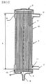
- FIG. 1 is a longitudinal sectional view of a hollow fiber membrane module for internal pressure type according to a first embodiment of the present invention. It is sectional drawing perpendicular
- FIG. 1 is a schematic view of a platelet suspension washing device using an internal pressure type hollow fiber membrane module according to a first embodiment of the present invention.
- the hollow fiber membrane module of the present invention is a hollow fiber membrane module that removes impurities from a platelet suspension to wash platelets, a housing having a platelet suspension inlet, a washed platelet outlet, and a filtrate outlet, Platelets do not pass but the contaminants have holes to pass through, and are disposed inside the housing, and include a hollow fiber membrane that filters the platelet suspension, and communicates with the platelet suspension inlet,
- the volume of the inflow side space containing the platelet suspension before being filtered by the hollow fiber membrane in the housing is 30 to 400 mL
- the module water permeability is 50 to 300 mL / Pa / hr. It is characterized by that.
- FIG. 1 is a longitudinal sectional view of a hollow fiber membrane module 1 for internal pressure
- FIG. 2 is a sectional view perpendicular to the longitudinal direction of the hollow fiber membrane module 1 for internal pressure.
- the platelet suspension is passed through the hollow part of the hollow fiber membrane for filtration.
- An internal pressure type hollow fiber membrane module 1 includes a tubular member 2, a housing having headers 3 and 4 that are liquid-tightly connected and fixed to both ends of the tubular member 2, and a hollow fiber membrane 5 accommodated inside the housing. It consists of a bundle of.
- a platelet suspension flow inlet 6 for introducing the platelet suspension into the hollow fiber membrane module protrudes from the top of the header 3, and a bundle 5 of hollow fiber membranes is formed on the top of the header 4.
- the washed platelet outlet 7 for discharging the liquid containing the washed platelets separated from the platelet suspension is formed to protrude.
- a filtrate outlet 8 for discharging a filtrate containing impurities such as proteins separated from the platelet suspension is formed on the side of the tubular member 2 on the header 4 side.
- the bundle of hollow fiber membranes 5 is arranged over the entire length in the long axis direction in the cylindrical member 2, and both ends of the hollow fiber membranes 5 are the hollow fiber membrane hollow portions 13 that are the lumens of the hollow fiber membranes 5.
- the opening is not blocked, and is fixed inside the cylindrical member 2 by a partition wall 9 on the header 3 side and a partition wall 10 on the header 4 side formed by a hardened potting agent.
- the inflow side space 11 is a space through which the platelet suspension before filtration flows.
- the inflow side space 11 includes a space surrounded by the header 3 and the partition wall 9 shown in FIG. 1, a space surrounded by the header 4 and the partition wall 10, and a hollow fiber shown in FIG. It refers to a space in which the spaces in the membrane hollow portion 13 are collected.
- the inflow side space 11 communicates with the platelet suspension inlet 6 and the washed platelet outlet 7. Furthermore, the inflow side space can also be referred to as a platelet side space.
- the platelet suspension flowing in the inflow side space 11 is filtered by passing through the pores present on the surface of the hollow fiber membrane 5, and the filtrate containing contaminants such as proteins permeates the pores and passes through the filtration side space. 12 flows.
- the filtration-side space 12 is a space into which a filtrate containing impurities such as proteins that have passed through the pores of the hollow fiber membrane flows.
- the filtration side space 12 is a space excluding the hollow fiber membrane 5 and the hollow fiber membrane hollow portion 13 among the spaces sandwiched between the tubular member 2 and the partition walls 9 and 10. Point to. Further, the filtration side space 12 communicates with the filtrate discharge port 8.
- FIG. 3 is a longitudinal sectional view of the hollow fiber membrane module 14 for external pressure type
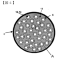
- FIG. 4 is a sectional view perpendicular to the longitudinal direction of the hollow fiber membrane module 14 for external pressure type.
- a hollow fiber membrane module for external pressure type filtration is performed by flowing a platelet suspension into a space outside the hollow fiber membrane.
- the external pressure type hollow fiber membrane module which is 2nd Embodiment, what has the same function is demonstrated using the same numbering.
- the hollow fiber membrane module 14 for external pressure type includes a tubular member 2, a housing having headers 3 and 4 that are liquid-tightly connected and fixed to both ends of the tubular member 2, and a hollow fiber membrane 5 that is housed inside the housing. It consists of a bundle of.
- a platelet suspension inlet 6 for introducing the platelet suspension into the hollow fiber membrane module is formed on the side of the tubular member 2 on the header 3 side, and on the header 4 side of the tubular member 2.
- a washed platelet outlet 7 for discharging a liquid containing washed platelets separated from the platelet suspension by being filtered by the bundle 5 of hollow fiber membranes is formed so as to protrude.
- a filtrate outlet 8 is formed at the top of the header 4 for discharging the filtrate containing unnecessary protein separated from the platelet suspension.
- the bundle of hollow fiber membranes 5 is arranged over the entire length in the long axis direction in the cylindrical member 2, and both ends of the hollow fiber membranes 5 are the hollow fiber membrane hollow portions 13 that are the lumens of the hollow fiber membranes 5.
- the opening is not blocked, and is fixed inside the cylindrical member 2 by a partition wall 9 on the header 3 side and a partition wall 10 on the header 4 side formed by a hardened potting agent.
- the hollow fiber membrane 5 at the end far from the filtrate outlet 8 is used, but in the external pressure type hollow fiber membrane module, the hollow fiber far from the filtrate outlet 8 is used.
- the end of the membrane 5 may be closed or may be folded back into a U shape.
- the inflow side space 11 is a space in which the platelet suspension before filtration stays.
- the inflow side space 11 is a space excluding the hollow fiber membrane 5 and the hollow fiber membrane hollow portion 13 among the spaces sandwiched between the tubular member 2 and the partition walls 9 and 10. Point to.
- the inflow side space 11 communicates with the platelet suspension inlet 6 and the washed platelet outlet 7.
- the filtration side space 12 includes a space surrounded by the header 3 and the partition wall 9, a space surrounded by the header 4 and the partition wall 10, and a space in the hollow fiber membrane hollow portion 13. It refers to the space where Further, the filtration side space 12 communicates with the filtrate discharge port 8.
- FIG. 5 is a schematic diagram of a platelet suspension washing device using the internal pressure type hollow fiber membrane module according to the first embodiment of the present invention.
- a bag for storing platelet suspension and a bag for storing preservation solution are arranged in parallel in the uppermost stream of the circuit connected to the platelet suspension inlet 6 and a tube clamp 17 is arranged downstream so that connection to the circuit can be switched.
- a pump 16 for sending the platelet suspension and the preservation solution and a gas are supplied to the internal pressure type hollow fiber membrane module 1.
- An air chamber 15 is arranged for preventing the contamination.
- a bag for storing the filtrate is arranged downstream of the circuit connected to the filtrate outlet 8, and a bag for storing the washed platelets is arranged downstream of the circuit connected to the washed platelet outlet 7, so that the connection to the circuit can be switched.
- a tube clamp 17 is arranged upstream of the bag.
- the platelet suspension is a liquid obtained by removing blood cell components from blood and separating and collecting platelets and plasma.
- This platelet suspension may be added with an anticoagulant such as citric acid or a preservation solution.
- the preservation solution is a liquid that stably suspends platelets in the liquid.
- a liquid containing bicarbonate is preferably used.
- the washing liquid is a liquid for washing platelets stably.
- a liquid containing bicarbonate is preferably used in the same manner as the storage liquid in order to perform stable cleaning.
- the method for producing washed platelets from the platelet suspension using the hollow fiber membrane module of the present invention is not particularly limited, but as a specific example, producing washed platelets by the method described below. Can do.
- the platelet suspension is completely filtered from the inflow side space of the hollow fiber membrane module to the filtration side space, and the filtrate containing contaminants such as proteins is allowed to permeate the filtration side space.
- the washing liquid is allowed to flow from the inflow side space to the filtration side space, and the protein and other contaminants remaining in the platelet-containing liquid are passed to the filtration side space. It has a washing process for permeating and removing contaminants such as proteins, and a collecting process for collecting a liquid containing washed platelets by flowing a preservation solution into the inflow side space.
- the platelet suspension is introduced from the platelet suspension inlet of the hollow fiber membrane module, and the whole amount is filtered from the inflow side space to the filtration side space.
- the filtrate containing contaminants such as proteins in the platelet suspension flows through the hollow fiber membrane, flows into the filtration side space, and is discharged from the communicating filtrate outlet.
- platelets in the platelet suspension cannot pass through the hollow fiber membrane and remain in the inflow side space.
- the washing liquid is filtered in the same manner, so that contaminants such as proteins remaining in the inflow side space permeate the hollow fiber membrane and flow into the filtration side space, and communicate with the filtrate. It is discharged from the outlet as a filtrate containing contaminants such as proteins.
- the preservation solution is introduced into the inflow side space from the platelet suspension inlet, so that the preservation solution and the platelet are mixed and released from the washed platelet outlet as a liquid containing platelets.
- washed platelets having the same platelet concentration as before the treatment can be obtained by making the amount of the platelet suspension used as the raw material the same as the amount of the preservation solution.
- the amount of liquid that is filtered in the filtration step increases, so the amount of contaminants such as proteins remaining in the inflow side space can be reduced.
- the washing efficiency is improved, and the removal rate of contaminants such as proteins can be increased with a small amount of washing solution.
- the amount of the preservation solution used for recovery relative to the amount of the liquid in the inflow side space is reduced, so the platelet recovery rate is lowered.
- the volume of the inflow side space of the hollow fiber membrane module needs to be 30 mL or more, and preferably 70 mL or more. Moreover, 400 mL or less is required and it is preferable that it is 200 mL or less.
- platelets clog the surface of the hollow fiber membrane during the process of filtering the platelet suspension by the total filtration method, and the filtration pressure rises. Clogging further proceeds by agglomeration due to strong pressing against the membrane.
- platelets aggregate, they adhere to the surface of the hollow fiber membrane and remain on the surface of the hollow fiber membrane without being peeled off even when a storage solution is passed for platelet recovery. descend.
- the aggregated platelets block the hollow portion.
- it is difficult to pass through the hollow portion of the hollow fiber membrane so that the platelet recovery rate decreases.
- platelet suspensions used for blood transfusion often have a platelet concentration that is three times or more concentrated in the body, so that clogging is likely to occur during filtration.
- the water permeability performance of the hollow fiber membrane module is determined by the water permeability performance and membrane area of the built-in hollow fiber membrane, so increasing the water permeability performance involves increasing the membrane area and the water permeability performance of the hollow fiber membrane.
- the membrane area of the hollow fiber membrane is increased, the hollow fiber membrane module becomes large, and there are problems such as deterioration in handleability and an increase in the amount of washing liquid before use of the hollow fiber membrane module.
- the optimum water permeability of the hollow fiber membrane was found to increase the platelet recovery rate while maintaining the handleability of the hollow fiber membrane module.
- the water permeability of the hollow fiber membrane module needs to be 2.5 mL / Pa / hr or more, and preferably 4 mL / Pa / hr or more.
- 15 mL / Pa / hr or less is required, and 13 mL / Pa / hr or less is preferable.
- the porosity of the hollow fiber membrane surface in the inflow side space is preferably 10% or more, and more preferably 12% or more.
- the hole area ratio is preferably 30% or less, and more preferably 20% or less.
- the open area ratio is the ratio of the total area of pores on the surface of the hollow fiber membrane to the area of the membrane surface of the hollow fiber membrane.
- the filtration pressure in the filtration step is preferably 30 kPa or less.
- a raw material for washed platelets 5, 10, 15, and 20 units of platelet suspension are generally used. Among them, 10 units of platelet suspension are most used.
- the platelet concentration of 10 units is a platelet concentration of 8.3 ⁇ 10 8 cells / mL or more and 1.8 ⁇ 10 9 cells / mL or less, and the liquid volume is 160 mL or more and 240 mL or less. .
- the hollow fiber membrane module of the present invention has a maximum filtration pressure of 30 kPa or less when 200 mL of a 1.25 ⁇ 10 9 platelet / mL platelet suspension, which is a 10-unit platelet preparation, is filtered at a flow rate of 50 mL / min. It is preferable that the pressure is 20 kPa or less.
- the filtration step stress due to shear is applied to the platelets due to contact with the surface of the hollow fiber membrane on the supply space side. It is known that platelets are activated when a strong shear stress is applied to platelets. Therefore, by reducing the shear stress applied to platelets in the filtration process, platelet aggregation is suppressed and the platelet recovery rate is increased. be able to. On the other hand, in the recovery step, increasing the shear stress applied to the platelets makes it easier for the platelets adhering to the hollow fiber membrane surface to be peeled off, thereby increasing the platelet recovery rate.
- the shear stress applied to the platelets is proportional to the linear velocity flowing through the hollow fiber membrane module.
- L / A is 250 m ⁇ 1 or more in order to increase the linear velocity and peel the platelets adhering to the hollow fiber membrane to increase the platelet recovery rate.
- 500 m ⁇ 1 or more is more preferable.
- L / A is preferably 1300 m -1 or less, more preferably 700 meters -1 or less.
- the effective length of the hollow fiber membrane is the length of the hollow fiber membrane that can be substantially filtered, and is the length excluding the partition wall of the hollow fiber membrane and the portion buried in the partition wall.
- the membrane area of the hollow fiber membrane module is also calculated based on this effective length.
- the area (A) of the cross section of the inflow side space perpendicular to the longitudinal direction of the housing is the area of the cross section of the hollow portion of the hollow fiber membrane in the internal pressure type hollow fiber membrane module, and is calculated by Equation 1.
- the hollow fiber membrane built in the hollow fiber membrane module is composed of two or more types of hollow fiber membranes having different hollow fiber inner diameters
- the values obtained by using Equation 1 are integrated for each hollow fiber membrane.
- the cross-sectional area (A) of the inflow side space perpendicular to the longitudinal direction of the housing is calculated.
- the area (A) of the cross section of the inflow side space perpendicular to the longitudinal direction of the housing is the cross section of the housing without the platelet suspension inlet and the washed platelet outlet in the external pressure type hollow fiber membrane module. This is a value obtained by subtracting the area of the cross section of the hollow fiber membrane from the area of.
- the hollow fiber membrane built in the hollow fiber membrane module is composed of two or more types of hollow fiber membranes having different hollow fiber outer diameters
- the values obtained by using Equation 2 for each hollow fiber membrane are integrated.
- the cross-sectional area (A M ) of the hollow fiber membrane is calculated.
- the area of the cross section of the housing is an average value in the same section as the effective length of the hollow fiber membrane in the longitudinal direction of the housing. For example, when the shape of the housing changes continuously in the longitudinal direction, the cross-sectional area at a total of 5 points at equal intervals from one end to the other end in the same section as the effective length of the hollow fiber membrane in the longitudinal direction. To calculate the arithmetic average.
- the cross-sectional area is measured for each part having a different shape, and the proportion of each part in the same section as the effective length of the hollow fiber membrane in the longitudinal direction is determined. Multiply and add together to determine the average cross-sectional area of the housing.
- the hollow fiber membrane used in the hollow fiber membrane module is not particularly limited as long as it is a hollow fiber membrane made of a material having so-called blood compatibility that suppresses the activation of platelets.
- a hollow fiber membrane used in a known method for producing washed platelets for example, a hollow fiber membrane described in Patent Documents 2 and 3 can be preferably used.
- the material for the hollow fiber membrane include, but are not limited to, a polysulfone polymer, polystyrene, polyurethane, polyethylene, polypropylene, polycarbonate, polyvinylidene fluoride, polyacrylonitrile, and the like.
- hollow fiber membranes made mainly of so-called polysulfone polymers such as polysulfone and polyethersulfone are known to be excellent in water permeability and fractionation performance.
- a polysulfone polymer is suitably used as the material to be used.
- the polysulfone polymer refers to a polymer having an aromatic ring, a sulfonyl group, and an ether group in its main chain.
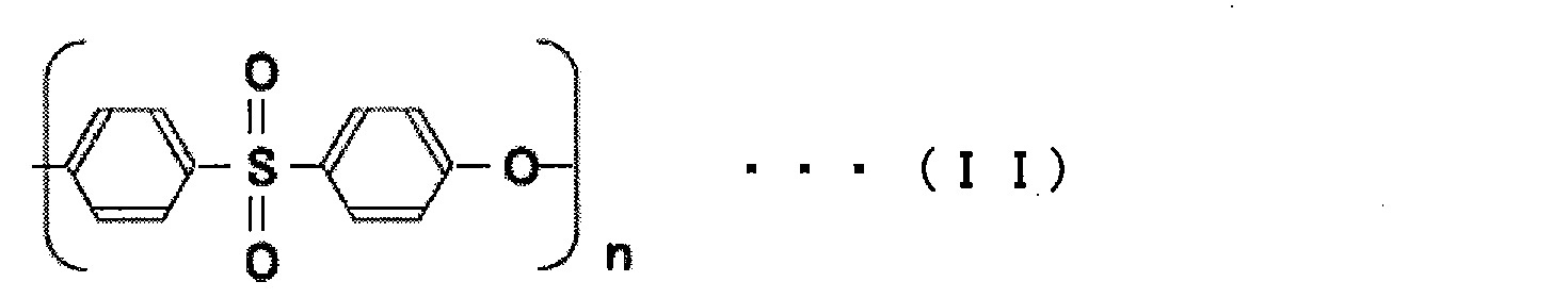
- polysulfone-based polymer examples include polysulfone represented by the general formula (I), polysulfone represented by the general formula (II), polyether sulfone, and polyallyl ether sulfone.
- the general formula (I ) and a polysulfone represented by the general formula (II) are preferable, and those having an n number of 50 to 80 are more preferable.
- the polysulfone-derived structure in the block copolymer of the polysulfone represented by the general formula (I) or (II) and another monomer is preferably 90% by mass or more based on the entire block copolymer.
- the inner diameter and thickness of the hollow fiber membrane are not particularly limited, but those having an inner diameter of about 100 to 500 ⁇ m and a thickness of about 30 to 200 ⁇ m can be preferably used.
- the average pore diameter of the pores of the hollow fiber membrane may be any diameter as long as platelets do not pass through but contaminants pass through, but the size of platelets to be washed, particularly human platelets, is 2 to 2 Since it is 4 ⁇ m, it is 1.5 ⁇ m or less, preferably 1 ⁇ m or less.
- the hollow fiber membrane constituting the hollow fiber membrane bundle has at least a surface on the side in contact with platelets (for example, if filtration is performed with an internal pressure method, at least the hollow fiber membrane to prevent activation of platelets in contact therewith) It is preferable that a hydrophilic component is contained in the lumen-side surface.
- the “hydrophilic component” refers to a substance that is easily soluble in water and has a solubility of 10 g / 100 g or more with respect to pure water at 20 ° C. More preferably, a hydrophilic polymer is preferably used among the hydrophilic components.
- the abundance ratio of the hydrophilic polymer with respect to all molecules from the surface of the hollow fiber membrane surface in the inflow side space to a depth of 10 nm is preferably 40% by mass or more.
- the hydrophilic polymer is present in excess, there is a concern that the hydrophilic polymer is eluted from the hollow fiber membrane and mixed into the washed blood product, and the pores of the hollow fiber membrane are caused by swelling on the surface of the hollow fiber membrane. There is a concern that the water transmission performance will be reduced. Therefore, the abundance ratio of the hydrophilic polymer with respect to all molecules from the surface of the hollow fiber membrane surface in the inflow side space to a depth of 10 nm is preferably 60% by mass or less.
- the hydrophilic polymer is a water-soluble polymer compound, or a polymer that interacts with water molecules by electrostatic interaction or hydrogen bonding even if it is water-insoluble.
- the hydrophilic polymer refers to a polymer that dissolves in pure water at 25 ° C. at a rate of 1000 ppm or more.
- Specific examples of hydrophilic polymers include, but are not limited to, polyalkylene glycols such as polyethylene glycol or polypropylene glycol, nonionic substances such as polyvinyl alcohol, polyvinyl pyrrolidone, polyvinyl acetic acid, polyvinyl caprolactam, hydroxyethyl methacrylate, or methyl methacrylate.
- examples include hydrophilic polymers or ionic hydrophilic polymers such as dextran sulfate, polyacrylic acid, polyethyleneimine, and polyallylamine.
- Examples of the method of incorporating a hydrophilic polymer on the surface of the hollow fiber membrane include a coating method using physical adsorption, a crosslinking method using heat or radiation, or a chemical bonding method using a chemical reaction.
- the injection solution is flowed inward when the membrane forming raw solution is discharged from the double annular die, and a hydrophilic polymer may be added to this injection solution. In this way, before the hollow fiber membrane is phase-separated and the membrane structure is determined, the hydrophilic polymer in the injection solution diffuses to the membrane forming stock solution side. Can be localized.
- the abundance ratio of the hydrophilic polymer with respect to all molecules from the surface of the hollow fiber membrane surface in the inflow side space to a depth of 10 nm is measured by X-ray electron spectroscopy (hereinafter “ESCA”) at a measurement angle of 90 °. It can be calculated by examining the abundance ratio of elements from the surface of the hollow fiber membrane to a depth of 10 nm. More specifically, it can be measured and calculated by the following method.
- ESA X-ray electron spectroscopy
- the hollow fiber membrane module used for the internal pressure type when measuring the depth of 10 nm from the surface of the hollow fiber membrane in the inflow side space, first the inner surface of the hollow fiber membrane is exposed by cutting it into a semi-cylindrical shape with a single blade. . After rinsing with ultrapure water, a sample dried for 10 hours at room temperature and 0.5 Torr is used as a measurement sample. The sample is set in the apparatus, and the measurement is performed at an angle of 90 ° by adjusting the angle of the detector with respect to the incident angle of X-rays. The abundance ratio of carbon atoms, nitrogen atoms and sulfur atoms is determined from the area intensity of each spectrum of C1s, N1s and S2p obtained and the relative sensitivity coefficient attached to the apparatus.
- the abundance ratio of polyvinylpyrrolidone on the surface is calculated by the following formula 4.
- the first pathway is a pathway in which platelets are activated at the same time as they contact the surface of the hollow fiber membrane and aggregate and adhere.
- the second pathway is a pathway in which proteins such as fibrinogen involved in blood coagulation adhere to the surface of the hollow membrane to activate platelets and induce platelet adhesion. For this reason, in order to suppress platelet adhesion to the hollow fiber membrane surface, it is necessary to prevent platelets from approaching the hollow fiber membrane surface and adhesion of proteins such as fibrinogen to the hollow fiber membrane surface.
- the diffuse layer As a means for preventing platelets from approaching the surface of the hollow fiber membrane, it is effective to form a diffuse layer with a hydrophilic polymer on the surface of the hollow fiber membrane. Due to the excluded volume effect of this diffuse layer, platelets do not approach the surface of the hollow fiber membrane. Formation of the diffuse layer can also prevent adhesion of proteins such as fibrinogen to the surface of the hollow fiber membrane. However, if the hydrophilicity of the diffuse layer is too strong, the binding water around the protein is trapped in the diffuse layer, causing a structural change of the protein and causing adhesion to the hollow fiber membrane surface. The protein adhesion inhibitory effect is reduced.
- the bound water refers to water that exists around the protein and whose mobility is restricted by hydrogen bonds. The bound water is said to stabilize the protein structure.
- the hydrophilic polymer suitable for the formation of this diffuse layer is preferably a water-insoluble polymer having a slightly hydrophobic unit such as vinyl caprolactam, propylene glycol, vinyl acetate, hydroxyethyl methacrylate or methyl methacrylate, and has an ester group.
- the polymer having a side chain type ester group such as a vinyl acetate group or a methyl acrylate group is more preferable.
- a side chain ester group such as a vinyl acetate group or a methyl acrylate group is presumed not to trap bound water because its hydrophilicity is appropriate.
- a polymer such as polyethylene terephthalate having strong hydrophobicity is not preferable.
- the copolymer is preferably a hydrophilic polymer, and has a good balance between water solubility and hydrophobicity, a copolymer of vinyl pyrrolidone and vinyl acetate, a copolymer of vinyl pyrrolidone and methyl methacrylate, ethylene glycol and acetic acid More preferably, a copolymer of vinyl or a copolymer of ethylene glycol and methyl methacrylate is a hydrophilic polymer.
- hydrophilic polymer suitable for the formation of the diffuse layer those having a balance between hydrophilicity and hydrophobicity in one molecule are preferable, and a random copolymer or an alternating copolymer is preferable.
- these copolymers have ester groups, the molar ratio of ester group units is preferably 0.3 to 0.7.
- the abundance of carbon atoms derived from ester groups with respect to all carbon atoms from the surface to the depth of 10 nm from the surface of the hollow fiber membrane in the inflow side space is measured by ESCA at a measurement angle of 90 °, and is about 10 nm from the surface of the hollow fiber membrane. It can be calculated by dividing the peak of the component derived from the ester group from the entire peak of C1s up to the depth of.
- the peak of the component derived from the ester group appears at +4.0 to 4.2 eV from the main peak (around 285 eV) of the component derived from CHx or the like.
- Ester group-derived peak area ratio (measured at three locations, and the average value (rounded to the first decimal place) is calculated for C1s carbon content (number of atoms%). Ester group-derived peak area ratio is 0.4%.
- the value obtained by multiplying by the detection limit or less) is the abundance ratio of the ester group-derived carbon atoms with respect to all the carbon atoms on the surface of the hollow fiber membrane in the inflow side space.
- the abundance of carbon atoms derived from the ester group is preferably 0.1 atomic percent or more, and more preferably 0.5 atomic percent or more.
- 10 atomic% or less is preferable, 5 atomic% or more is more preferable, 1 atomic% or more is further more preferable.
- the hydrophilic polymer in order to retain the hydrophilic polymer on the surface of the hollow fiber membrane, it is advantageous to have a large number of crosslinking points, that is, a polymer having a large weight average molecular weight.
- the weight average molecular weight is too high, it becomes difficult to maintain the membrane surface in a uniform state on the surface of the hollow fiber membrane due to high viscosity or gelation, and a swollen diffuse layer is not formed.
- the weight average molecular weight of the hydrophilic polymer is preferably 5000 to 1500,000, more preferably 10,000 to 1000000.
- the hydrophilic polymer may be of a single weight average molecular weight or may be a mixture of a plurality of different weight average molecular weights. Moreover, you may use what refine
- PVP polyvinylpyrrolidone
- K15 to K120 are preferred.
- the weight average molecular weight of PVP is preferably 10,000 or more, and more preferably 40000 or more.
- PVP is a water-soluble polymer obtained by vinyl polymerization of N-vinylpyrrolidone, for example, Rubitec (registered trademark) manufactured by BASF, Plasdon (registered trademark) manufactured by ISP, Pittscall manufactured by Daiichi Kogyo Seiyaku Co., Ltd. Products of various molecular weights are commercially available under the trade name (registered trademark).
- the weight ratio of PVP: vinyl acetate is (7: 3), (6: 4), (5: 5) or (3: 7).
- the method for controlling the abundance of the hydrophilic polymer on the surface of the hollow fiber membrane in the inflow side space is not particularly limited. There are a method of bringing a polymer solution into contact with the surface, a method of coating the surface with a hydrophilic polymer, and the like. Furthermore, after imparting a hydrophilic polymer to the surface by these methods, the hydrophilic polymer polymer may be cross-linked to the hollow fiber membrane by radiation or heat treatment, thereby increasing the hydrophilicity from the hollow fiber surface. Molecular elution can be suppressed. Alternatively, the hydrophilic polymer and the hollow fiber membrane may be immobilized by a chemical reaction.
- hydrophilic polymers existing on the surface of the hollow fiber membrane are crosslinked.
- the temperature for heat crosslinking is preferably 120 to 250 ° C., more preferably 130 to 200 ° C. so that no decomposition reaction occurs while the hydrophilic polymers are crosslinked.
- the heat crosslinking time is preferably 1 to 10 hours, and more preferably 3 to 8 hours.
- the hydrophilic polymer and the polysulfone polymer are crosslinked.
- the irradiation dose of the radiation crosslinking is preferably 5 to 75 kGy, more preferably 10 to 50 kGy.
- ⁇ rays, ⁇ rays, X rays, ⁇ rays, or electron beams are used, and among them, ⁇ rays or electron beams are preferable.
- a preservation solution with high preservation stability of platelet function In washed platelets, platelets are suspended in a preservation solution with high preservation stability of platelet function, instead of plasma removed during production.
- a storage solution containing bicarbonate is preferably used as a storage solution for recovering platelets in the hollow fiber membrane module.
- the volume of the air chamber is preferably 1 mL or more.
- the volume of the air chamber is preferably 30 mL or less.
- a constant pressure filtration method in which the solution is sent at a constant pressure
- a constant speed filtration method in which the solution is sent at a constant speed.
- a syringe pump and a roller pump as a liquid feeding means for flowing the platelet suspension at a constant speed.
- a roller pump is preferable because a large amount of platelet suspension can be fed.
- the ironing of the roller pump facilitates the generation of bubbles from the preservation solution containing bicarbonate. Therefore, it is preferable to arrange the roller pump, the air chamber, and the hollow fiber membrane module in this order from the upstream side of feeding the platelet suspension. .
- a hollow fiber membrane module for internal pressure because it is difficult to cause uneven speed of the platelet suspension, the hollow fiber membrane can be used uniformly, and platelet retention is also suppressed.
- the water permeability of the hollow fiber membrane module is calculated by measuring the water permeability per membrane area of the hollow fiber membrane cut out from the hollow fiber membrane module and multiplying by the membrane area of the hollow fiber membrane incorporated in the hollow fiber membrane module.
- the First, the water permeability per membrane area can be measured by the following method.
- a hollow fiber membrane built in the hollow fiber membrane module is cut out.
- a hollow fiber membrane was inserted into the plastic tube, and both ends of the hollow fiber membrane were potted on the inner walls of both ends of the plastic tube to produce a mini module having an effective length of 10 cm.
- the number of hollow fiber membranes was adjusted so that the membrane area of the minimodule was 0.003 m 2 .
- the membrane area is the membrane area based on the inner diameter when the hollow fiber membrane module is used in the internal pressure type, and the membrane area based on the outer diameter when the hollow fiber membrane module is used in the external pressure type.
- the membrane area of the mini module was calculated by the following formula 5.
- the hollow fiber membrane module contains two or more types of hollow fiber membranes
- the hollow fiber membrane module and the mini module have the same number ratio of the hollow fiber membranes, and the calculation of the membrane area also applies to each hollow fiber membrane.
- the values calculated by Equation 5 were integrated.
- a mini D ⁇ ⁇ ⁇ L ⁇ n Equation 5
- a mini Mini module membrane area (m 2 )
- D Hollow fiber diameter (m) (inner diameter for internal pressure type; outer diameter for external pressure type)
- ⁇ Circumference ratio
- L Effective length (m)
- n number of hollow fiber membranes
- a water pressure of 1.3 ⁇ 10 4 Pa was applied to the produced minimodule, and the amount of water per unit time released to the surface side where the filtrate of the hollow fiber membrane was obtained was measured.
- the water pressure is applied to the mini module with internal pressure.
- the mini module is external with pressure. Water pressure was applied.
- the water permeability of the hollow fiber membrane was calculated according to the following formula 6.
- F M Q / (T ⁇ P ⁇ A mini ) Equation 6
- F M Water permeability of hollow fiber membrane (mL / hr / Pa / m 2 )
- Q Amount of water released (mL)
- T Time for applying water pressure (hr)
- P Water pressure (Pa)
- a mini Mini module membrane area (m 2 )
- Equation 7 the membrane area of the hollow fiber membrane module was calculated by Equation 7.
- the values calculated by Equation 7 for each hollow fiber membrane were integrated.
- the water permeation performance of the hollow fiber membrane module was calculated by the following formula 8.
- a MD D ⁇ ⁇ ⁇ L ⁇ n Expression 7
- a MD Membrane area of the hollow fiber membrane module (m 2 )
- D Hollow fiber diameter (m) (inner diameter for internal pressure type; outer diameter for external pressure type)
- ⁇ Circumference ratio
- L Effective length (m)
- n number of hollow fiber membranes
- F MD F M ⁇ A MD Expression 8
- F MD Water permeability of hollow fiber membrane module (mL / Pa / hr)
- F M Water permeability of hollow fiber membrane (mL / hr / Pa / m 2 )
- a MD Membrane area of the hollow fiber membrane module (m 2 )
- Measurement of filtration pressure of platelet suspension The concentration of the platelet suspension was measured, and a platelet suspension was prepared so as to be 1.25 ⁇ 10 9 cells / mL. When the platelet concentration was low, the platelets were sedimented by centrifugation, and the supernatant was removed and concentrated. When the platelet concentration was high, a part of the platelet suspension was aliquoted, centrifuged to precipitate the platelets, and the supernatant was added to the original platelet suspension for dilution.
- the washed platelet outlet was closed, the platelet suspension inlet and the filtrate outlet were opened, and 200 mL of platelet suspension adjusted in concentration to the platelet suspension inlet was flowed at 50 mL / min, and the whole amount was filtered.
- the pressure P1 at the platelet suspension inlet, the pressure P2 at the washed platelet outlet, and the pressure Po at the filtrate outlet were measured.
- the filtration pressure was calculated from Equation 9 below.
- the shooting conditions for the 1000 ⁇ image are as follows.
- Measurement of the abundance of hydrophilic polymer to all molecules on the surface of the hollow fiber membrane The surface of the hollow fiber membrane in the inflow side space is exposed, rinsed with ultrapure water, and then dried at room temperature and 0.5 Torr for 10 hours as a measurement sample. Set the sample in an X-ray photoelectron spectrometer (for example, ESCALAB220i-XL manufactured by Thermo Fisher Scientific Co., Ltd. can be used), adjust the detector angle with respect to the X-ray incident angle, and set the measurement angle to 90 ° Measure.
- X-ray photoelectron spectrometer for example, ESCALAB220i-XL manufactured by Thermo Fisher Scientific Co., Ltd. can be used
- the membrane material is a polysulfone-based polymer and polyvinylpyrrolidone
- the measurement angle is 90 °
- the measurement is performed by XPS
- carbon atoms, nitrogen atoms and sulfur atoms at a depth of 10 nm from the membrane surface are measured.
- the abundance ratio of the hydrophilic polymer can be calculated with respect to all molecules from the surface of the hollow fiber membrane in the inflow side space to a depth of 10 nm by the following equation 12.
- Abundance ratio of hydrophilic polymer with respect to all molecules N ⁇ 111 / (N ⁇ 111 + S ⁇ 442)
- N Abundance ratio of nitrogen atom
- S Abundance ratio of sulfur atom
- 111 Number of repeating units of polyvinylpyrrolidone 442: Number of repeating units of polysulfone polymer
- Measurement of the abundance of ester-derived carbon atoms relative to all carbon atoms on the surface of the hollow fiber membrane Similar to the measurement of the abundance of the hydrophilic polymer on the surface of the hollow fiber membrane, measurement is performed with ESCA at a measurement angle of 90 °, and the entire C1s peak from the surface of the hollow fiber membrane in the inflow side space to a depth of 10 nm is measured. From the above, by dividing the peak of the component derived from the ester group, the abundance of the carbon derived from the ester group was calculated for all the carbon atoms.
- the peak of the component derived from the ester group appears at +4.0 to 4.2 eV from the main peak (around 285 eV) of the component derived from CHx or the like.
- Ester group-derived peak area ratio (measured at three locations and calculated the average value (rounded to the first decimal place)) to the carbon amount of C1s (number of atoms%); ester group-derived peak area ratio is 0.4%
- the value obtained by multiplying by the value below the detection limit is the abundance ratio of the ester group-derived carbon atoms to the total carbon atoms from the surface of the hollow fiber membrane in the inflow side space to a depth of 10 nm.
- Protein concentration measurement The protein concentration was measured by BCA method using BCA PROTEIN ASSAY KIT (manufactured by THERMO SCIENTIFIC). As a measurement sample, platelet suspension or washed platelets were centrifuged at 2000 ⁇ g for 10 minutes, and the supernatant was used. For measurement, first, a BCA reagent and a sample for a calibration curve were prepared. For sample dilution, M-sol, which is a stock solution used for the production of washed platelets, was used. According to the specification of the kit, the BCA reagent was added to the calibration curve sample or the measurement sample, and stirred at room temperature for 10 seconds using a micromixer. Then, it incubated at 37 degreeC for 30 minutes.
- the absorbance of the sample at a wavelength of 562 nm was measured.
- the wavelength at which the absorbance is measured is not strictly the same, but may be in the vicinity of the wavelength around ⁇ 20 nm.
- the protein concentration of the measurement sample was determined by drawing a calibration curve of protein concentration and absorbance from the calibration curve sample and substituting the absorbance of the measurement sample into the equation of the calibration curve.
- washed platelets Ten units of platelet suspension contains 2 ⁇ 10 11 to 3 ⁇ 10 11 platelets, and the volume is about 200 mL. The number of platelets in the platelet suspension was measured with a multi-item automatic blood cell counter XT1800i (manufactured by Sysmec). The protein concentration of the platelet suspension was measured.
- Terome Soletet F (registered trademark) 746.2 mL, Otsuka Pharmaceutical Meylon (registered trademark) 52.2 mL, Terumo ACD-A solution 126.8 mL, Otsuka Pharmaceutical Mg sulfate correction solution (1 mEq / mL) 3.2 mL and 71.6 mL of distilled water manufactured by Otsuka Pharmaceutical Co., Ltd. were added and mixed to prepare 1 L of M-sol as an artificial preservation solution.
- the platelet suspension was filtered by the hollow fiber membrane through the inflow side space of the hollow fiber membrane module, and the filtrate was discharged from the filtrate outlet through the filtration side space of the hollow fiber membrane module.
- the filtrate was discharged from the filtrate outlet through the filtration side space of the hollow fiber membrane module.
- platelets do not permeate the hollow fiber membrane, they remain in the inflow side space of the hollow fiber membrane module, and protein and water that permeate the hollow fiber membrane are discharged as a filtrate.
- 1000 mL of M-sol was washed at 50 mL / min as a washing solution through the same route.
- the filtrate outlet is closed, the platelet suspension inlet and the washed platelet outlet are opened, and 200 mL of M-sol as a preservation solution is added from the platelet suspension inlet to the hollow fiber membrane module at a flow rate of 250 mL / min. Poured into the inflow side space and released from the washed platelet outlet. The platelet concentration and protein concentration of the obtained washed platelets were measured. From the concentration and amount of platelet suspension and washed platelets, the protein removal rate was calculated using Equation 13, and the platelet recovery rate was calculated using Equation 14.
- Protein removal rate (%) (1 ⁇ (Co1 ⁇ Vo) / (Ci1 ⁇ Vi)) ⁇ 100 Equation 13
- Co1 Protein concentration of washed platelets (mg / mL)
- Ci1 Protein concentration of platelet suspension (mg / mL)
- Vo Volume of washed platelets (mL)
- Vi Volume of platelet suspension (mL)
- Platelet recovery rate (%) ((Co2 ⁇ Vo) / (Ci2 ⁇ Vi)) ⁇ 100 (14)
- Co2 Platelet concentration of washed platelets (pieces / mL)
- Ci2 Platelet concentration of platelet suspension (pieces / mL)
- Vo Volume of washed platelets (mL)
- Vi Volume of platelet suspension (mL)
- Example 1 After mixing a mixture of 15 parts Udel® polysulfone (P3500; Solvay), 8 parts PVP (K90; ISP), 75 parts DMAC and 2 parts water at 90 ° C., 50 The one kept at °C was used as a film forming stock solution. Further, a core solution was prepared by adding 30 parts of PVP (K30; ISP) to a mixed solution composed of 80 parts of DMAC and 20 parts of water and mixing and dissolving them.
- a film-forming stock solution was discharged from the outer cylinder and a core liquid was simultaneously discharged from the inner cylinder, and the length was set to 30 ° C. After passing through a 70 mm dry part, it is solidified by dipping in a 90 ° C. coagulation bath containing a mixed solution of 85 parts of water and 15 parts of DMAC, and further washed with warm water in an 80 ° C. hot water bath. Was wound around a cassette frame to obtain a wet hollow fiber membrane. When the film forming speed was 40 m / min, the inner diameter of the hollow fiber membrane was 300 ⁇ m, and the film thickness of the hollow fiber membrane was 80 ⁇ m.
- the wet hollow fiber membrane thus obtained was cut into 0.4 m lengths and subdivided, immersed in a 90 ° C. warm water bath for 50 minutes and washed with warm water, and then subjected to a drying treatment at 100 ° C. for 10 hours, Further, a heat-crosslinking treatment was performed at 170 ° C. for 5 hours with a dry heat dryer to obtain a hollow fiber membrane.
- a hollow fiber membrane module was produced from the obtained hollow fiber membrane as follows. First, a cylindrical member having an inner diameter of 50 mm and a length of 290 mm, the filtrate discharge port was provided at a location 21 mm from the end surface of the cylindrical member, that is, at a location 7% from the end surface length of the cylindrical member. A bundle of 6864 hollow fiber membranes obtained by the above film forming operation is inserted into a cylindrical plastic member, and the end portion is sealed with a potting agent made of polyurethane resin to provide a partition wall. Cut the potting agent along the direction parallel to the cross-section of the tubular member so that both sides of the hollow fiber membrane open toward the outside, and enter the platelet suspension at the end of the tubular member far from the filtrate outlet.
- the hollow fiber membrane module is filled with a VA64 1000ppm aqueous solution in which 0.1% by mass of ethanol is dissolved in a housing containing a hollow fiber membrane and irradiated with ⁇ rays 25kGy from the outside of the housing for radiation irradiation crosslinking treatment.
- the obtained hollow fiber membrane module is for internal pressure type, and the inflow side space of the hollow fiber membrane module is the inside of both headers and the hollow part of the hollow fiber membrane.
- the effective length (L) of the hollow fiber membrane is 255 mm, and the cross-sectional area (A) of the hollow portion of the hollow fiber membrane (the cross-sectional area of the inflow side space perpendicular to the longitudinal direction of the housing) is 0.00049 m 2 . there were. Therefore, the ratio (L / A) of the effective length (L) of the hollow fiber membrane to the cross-sectional area (A) of the hollow portion of the hollow fiber membrane was 520 m ⁇ 1 .
- the volume of the inflow side space of the hollow fiber membrane module was 155 mL.
- the water permeability of the hollow fiber membrane module was 125 mL / Pa / hr.
- the porosity of the surface of the hollow fiber membrane in the inflow side space is 17.3%
- the abundance of the hydrophilic polymer from the surface in the hollow fiber membrane of the inflow side space to a depth of 10 nm is 54.2%
- the peak area percentage of carbon atoms derived from ester groups with respect to all carbon atoms from the surface to the depth of 10 nm on the surface of the hollow fiber membrane was 0.5 atomic%.
- the maximum pressure was 5 kPa.
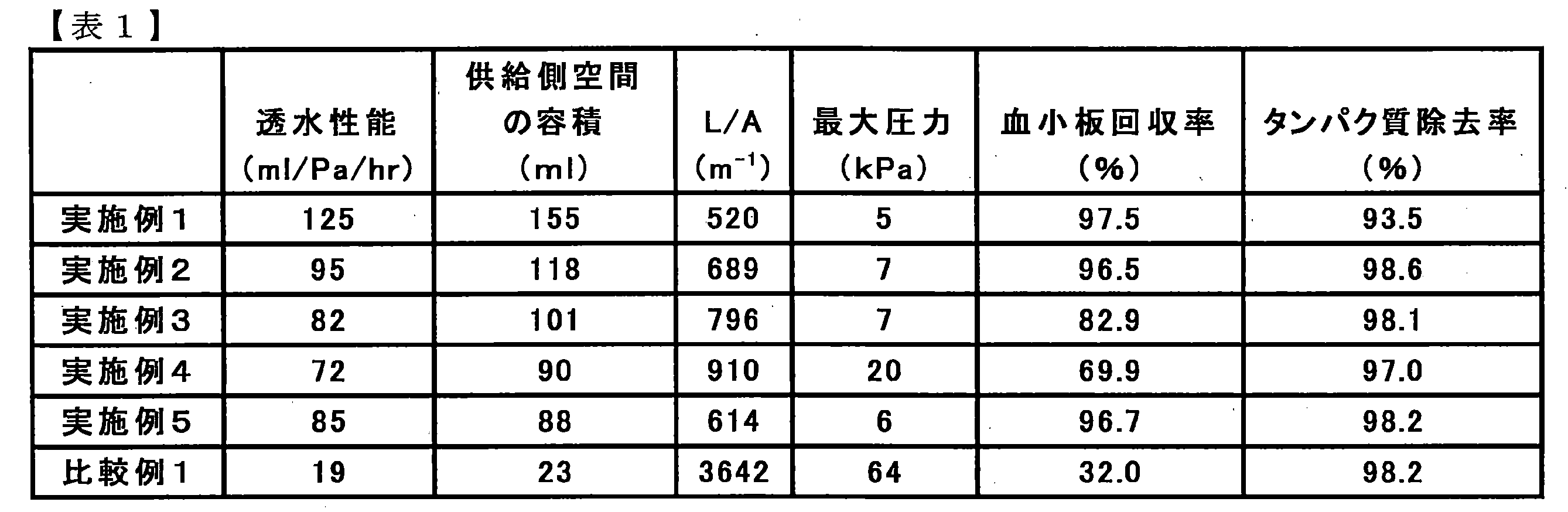
- the platelet recovery rate was 97.5% and the protein removal rate was 93.5%. Since the water permeability of the hollow fiber membrane module was high and the filtration pressure was difficult to increase, the platelet recovery rate in the whole volume filtration method was high. Washed platelets with high platelet concentration and low protein concentration could be produced. The results are shown in Table 1 as Example 1.
- Example 2 A hollow fiber membrane module was produced in the same manner as in Example 1 except that the inner diameter of the tubular member was 44 mm, the header volume was 6.4 mL, and the number of hollow fiber membranes to be inserted was 5243.
- the effective length (L) of the hollow fiber membrane is 255 mm, and the cross-sectional area (A) of the hollow portion of the hollow fiber membrane (the cross-sectional area of the inflow side space perpendicular to the longitudinal direction of the housing) is 0.00037 m 2. It was. Therefore, the ratio (L / A) of the effective length (L) of the hollow fiber membrane to the area (A) of the cross section of the hollow portion of the hollow fiber membrane was 689 m ⁇ 1 .
- the volume of the inflow side space of the hollow fiber membrane module was 118 mL.
- the water permeability of the hollow fiber membrane module was 95 mL / Pa / hr.
- the porosity of the surface of the hollow fiber membrane in the inflow side space is 17.3%
- the abundance of the hydrophilic polymer from the surface in the hollow fiber membrane of the inflow side space to a depth of 10 nm is 54.2%
- the peak area percentage of carbon atoms derived from ester groups with respect to all carbon atoms from the surface to a depth of 10 nm in the hollow fiber membrane was 0.5 atomic%.
- the maximum pressure was 7 kPa.
- Example 3 A hollow fiber membrane module was prepared in the same manner as in Example 1 except that the inner diameter of the cylindrical member was 40 mm, the header volume was 5.3 mL, and the number of hollow fiber membranes to be inserted was 4494.
- the effective length (L) of the hollow fiber membrane is 255 mm, and the cross-sectional area (A) of the hollow portion of the hollow fiber membrane (the cross-sectional area of the inflow side space perpendicular to the longitudinal direction of the housing) is 0.00032 m 2. It was. Therefore, the ratio (L / A) of the effective length (L) of the hollow fiber membrane to the cross-sectional area (A) of the hollow portion of the hollow fiber membrane was 796 m ⁇ 1 .
- the volume of the inflow side space of the hollow fiber membrane module was 101 mL.
- the water permeability of the hollow fiber membrane module was 82 mL / Pa / hr.
- the porosity of the hollow fiber membrane surface in the inflow side space is 17.3%, the abundance of hydrophilic polymer from the surface of the hollow fiber membrane surface in the inflow side space to a depth of 10 nm is 54.2%, the inflow side space
- the percentage of the peak area of carbon atoms derived from the ester group with respect to all the carbon atoms from the surface to the depth of 10 nm in the hollow fiber membrane was 0.5 atomic%. In the measurement of the filtration pressure, the maximum pressure was 7 kPa.
- Example 4 A hollow fiber membrane module was produced in the same manner as in Example 1 except that the inner diameter of the cylindrical member was 38 mm, the header volume was 4.8 mL, and the number of hollow fiber membranes to be inserted was 3955.
- the effective length (L) of the hollow fiber membrane is 255 mm, and the cross-sectional area (A) of the hollow portion of the hollow fiber membrane (the cross-sectional area of the inflow side space perpendicular to the longitudinal direction of the housing) is 0.00028 m 2. It was. Therefore, the ratio (L / A) of the effective length (L) of the hollow fiber membrane to the cross-sectional area (A) of the hollow portion of the hollow fiber membrane was 910 m ⁇ 1 .
- the volume of the inflow side space of the hollow fiber membrane module was 90 mL.
- the water permeability of the hollow fiber membrane module was 72 mL / Pa / hr.
- the porosity of the surface of the hollow fiber membrane in the inflow side space is 17.3%
- the abundance of the hydrophilic polymer from the surface in the hollow fiber membrane of the inflow side space to a depth of 10 nm is 54.2%
- the peak area percentage of carbon atoms derived from ester groups with respect to all carbon atoms from the surface to a depth of 10 nm in the hollow fiber membrane was 0.5 atomic%.
- the maximum pressure was 20 kPa.
- Example 5 A hollow fiber membrane module was produced in the same manner as in Example 1 except that the length of the cylindrical member was 220 mm and the number of hollow fiber membranes to be inserted was 4600.
- the effective length (L) of the hollow fiber membrane is 198 mm, and the cross-sectional area (A) of the hollow portion of the hollow fiber membrane (the cross-sectional area of the inflow side space perpendicular to the longitudinal direction of the housing) is 0.00032 m 2. It was. Therefore, the ratio (L / A) of the effective length (L) of the hollow fiber membrane to the cross-sectional area (A) of the hollow portion of the hollow fiber membrane was 614 m ⁇ 1 .
- the volume of the inflow side space of the hollow fiber membrane module was 88 mL.
- the water permeability of the hollow fiber membrane module was 85 mL / Pa / hr.
- the porosity of the surface of the hollow fiber membrane in the inflow side space is 17.3%
- the abundance of the hydrophilic polymer from the surface in the hollow fiber membrane of the inflow side space to a depth of 10 nm is 54.2%
- the peak area percentage of carbon atoms derived from ester groups with respect to all carbon atoms from the surface to a depth of 10 nm in the hollow fiber membrane was 0.5 atomic%.
- the maximum pressure was 6 kPa.
- Example 1 A hollow fiber membrane module was produced in the same manner as in Example 1 except that the inner diameter of the cylindrical member was 19 mm, the header volume was 1.2 mL, and the number of hollow fiber membranes to be inserted was 1000.
- the effective length (L) of the hollow fiber membrane is 255 mm, and the cross-sectional area (A) of the hollow portion of the hollow fiber membrane (the cross-sectional area of the inflow side space perpendicular to the longitudinal direction of the housing) is 0.00007 m 2. It was. Therefore, the ratio (L / A) of the effective length (L) of the hollow fiber membrane to the area (A) of the cross section of the hollow portion of the hollow fiber membrane was 3642 m ⁇ 1 .
- the volume of the inflow side space of the hollow fiber membrane module was 23 mL.
- the water permeability of the hollow fiber membrane module was 19 mL / Pa / hr.
- the porosity of the surface of the hollow fiber membrane in the inflow side space is 17.3%
- the abundance of the hydrophilic polymer from the surface in the hollow fiber membrane of the inflow side space to a depth of 10 nm is 54.2%
- the peak area percentage of carbon atoms derived from ester groups with respect to all carbon atoms from the surface to a depth of 10 nm in the hollow fiber membrane was 0.5 atomic%.
- the maximum pressure was 64 kPa.
- the platelet recovery rate was 32% and the protein removal rate was 98.2%.
- the hollow fiber membrane has a low water permeability, L / A is large, and the volume of the inflow side space of the hollow fiber membrane module is small. Platelet recovery rate decreased. The results are shown in Table 1.
- the hollow fiber membrane module of the present invention it is possible to remove impurities such as proteins at a high rate from the platelet suspension without lowering the platelet concentration, the protein concentration is low, and the platelet concentration is low. High wash platelets can be produced.
- SYMBOLS 1 Hollow fiber membrane module for internal pressure types, 2 ... Cylindrical member, 3 ... Header, 4 ... Header, 5 ... Hollow fiber membrane, 6 ... Platelet floating liquid inflow port 7 ... Washing platelet outlet, 8 ... Filtrate outlet, 9 ... Partition, 10 ... Partition, 11 ... Inflow side space, 12 ... Filtration side space, 13 ... Hollow fiber membrane hollow part, 14 ... hollow fiber membrane module for external pressure type, 15 ... air chamber, 16 ... roller pump, 17 ... tube clamp
Landscapes
- Health & Medical Sciences (AREA)
- Heart & Thoracic Surgery (AREA)
- Vascular Medicine (AREA)
- Engineering & Computer Science (AREA)
- Anesthesiology (AREA)
- Biomedical Technology (AREA)
- Hematology (AREA)
- Life Sciences & Earth Sciences (AREA)
- Animal Behavior & Ethology (AREA)
- General Health & Medical Sciences (AREA)
- Public Health (AREA)
- Veterinary Medicine (AREA)
- Chemical & Material Sciences (AREA)
- Chemical Kinetics & Catalysis (AREA)
- External Artificial Organs (AREA)
- Separation Using Semi-Permeable Membranes (AREA)
Abstract
Description
(1) 血小板浮遊液から夾雑物を除去して血小板を洗浄する中空糸膜モジュールであり、 血小板浮遊液流入口、洗浄血小板流出口及び濾液排出口を有するハウジングと、上記血小板は通過しないが上記夾雑物は通過する孔を有し、上記ハウジングの内部に配置されて、上記血小板浮遊液を濾過する中空糸膜と、を備え、上記血小板浮遊液流入口と連通し、上記ハウジング内における上記中空糸膜で濾過される前の上記血小板浮遊液を収容する流入側空間の容積が、30~400mLであり、かつ、モジュール透水性能が、50~300mL/Pa/hrである、中空糸膜モジュール。
(2) 上記ハウジングの長手方向に対して垂直な上記流入側空間の断面の面積(A)に対する上記中空糸膜の有効長(L)の比(L/A)が、250~1300m-1である、上記(1)記載の中空糸膜モジュール。
(3) 1.25×10⁹個/mLの血小板浮遊液の200mLを50mL/分の流速で全量濾過したときの濾過圧力の最大圧力が、30kPa以下である、上記(1)又は(2)記載の中空糸膜モジュール。
(4) 上記流入側空間に面する中空糸膜の表面の開孔率が、10~30%である、上記(1)~(3)のいずれか記載の中空糸膜モジュール。
(5) 上記中空糸膜は、ポリスルホン系高分子からなる膜である、上記(1)~(4)のいずれか記載の中空糸膜モジュール。
(6) 上記流入側空間に面する中空糸膜の表面から10nmの深さまでの全分子に対する親水性高分子の存在率が、40~60質量%である、上記(1)~(5)のいずれか記載の中空糸膜モジュール。
(7) 上記流入側空間に面する中空糸膜の表面から10nmの深さまでの全炭素原子に対するエステル基由来の炭素原子の存在率が、0.1~10原子数%である、上記(1)~(6)のいずれか記載の中空糸膜モジュール。
(8) 上記(1)~(7)のいずれか記載の中空糸膜モジュールと、血小板浮遊液流入口の上流側に配置され、容積が1~30mLであるエアーチャンバーと、を備える、血小板浮遊液洗浄用デバイス。
(9) ローラーポンプが、上記エアーチャンバーに対して上記血小板浮遊液の液流の上流側に配置されている、上記(8)記載の血小板浮遊液洗浄用デバイス。
A : ハウジングの長手方向に対して垂直な流入側空間の断面の面積(m2)
ID : 中空糸内径(m)
π : 円周率
n : 中空糸膜の本数
A=AH-AM ・・・式3 A : ハウジングの長手方向に対して垂直な流入側空間の断面の面積(m2)
AH : ハウジングの断面の面積
AM : 中空糸膜の断面の面積
OD : 中空糸外径(m)
π : 円周率
n : 中空糸膜の本数

N : 窒素原子の存在比率
S : 硫黄原子の存在比率
111: ポリビニルピロリドンの繰り返し単位数
442: ポリスルホン系高分子の繰り返し単位数
中空糸膜モジュールの透水性能は、中空糸膜モジュールから切り出した中空糸膜の膜面積あたりの透水性能を測定し、中空糸膜モジュールに内蔵される中空糸膜の膜面積を乗ずることで算出される。まず、膜面積あたりの透水性は以下の方法により測定することができる。中空糸膜モジュールに内蔵される中空糸膜を切り出す。プラスチック管に中空糸膜を挿入し、中空糸膜の両端をプラスチック管両端部の内壁にポッティングして、有効長10cmのミニモジュールを作製した。中空糸膜の本数は、ミニモジュールの膜面積が0.003m2になるように調整した。膜面積は、中空糸膜モジュールが内圧式で用いられる場合には、内径ベースの膜面積であり、中空糸膜モジュールが外圧式で用いられる場合には、外径ベースの膜面積である。ミニモジュールの膜面積を、以下の式5により算出した。ここで、中空糸膜モジュールが2種類以上の中空糸膜を内蔵する場合、中空糸膜モジュールとミニモジュールの各中空糸膜の本数比率を同じにし、膜面積の計算においても各中空糸膜について式5により算出した値を積算した。
Amini : ミニモジュールの膜面積(m2)
D : 中空糸直径(m)(内圧式の場合は内径。外圧式の場合は外径)
π : 円周率
L : 有効長(m)
n : 中空糸膜の本数
FM : 中空糸膜の透水性能(mL/hr/Pa/m2)
Q : 放出した水の量(mL)
T : 水圧をかけた時間(hr)
P : 水圧(Pa)
Amini : ミニモジュールの膜面積(m2)
AMD : 中空糸膜モジュールの膜面積(m2)
D : 中空糸直径(m)(内圧式の場合は内径。外圧式の場合は外径)
π : 円周率
L : 有効長(m)
n : 中空糸膜の本数
FMD : 中空糸膜モジュールの透水性能(mL/Pa/hr)
FM : 中空糸膜の透水性能(mL/hr/Pa/m2)
AMD : 中空糸膜モジュールの膜面積(m2)
血小板浮遊液の濃度を測定し、1.25×10⁹個/mLとなるように、血小板浮遊液を調製した。血小板濃度が低い場合は遠心分離で血小板を沈降させて上澄みを除去して濃縮した。血小板濃度が高い場合は血小板浮遊液の一部を小分けし、遠心分離して血小板を沈降させ、上澄みを元の血小板浮遊液に添加して希釈した。洗浄血小板流出口を閉止して、血小板浮遊液流入口および濾液排出口を開放し、血小板浮遊液流入口に濃度調整した血小板浮遊液200mLを、50mL/minで流し、全量濾過した。血小板浮遊液流入口の圧力P1、洗浄血小板流出口の圧力P2、濾液排出口の圧力Poを測定した。以下の式9より、濾過圧力を算出した。
走査型電子顕微鏡で、血小板浮遊液と接触する側である、流入側空間の中空糸膜の膜表面の1000倍画像を撮影した。次に、Matrox Inspector2.2(Matrox Electronic Systems Ltd.)で、孔の部分を白く、それ以外の部分を黒く反転させる画像処理を行い、白い孔の個数(以下、「総開孔数」)及び白い孔の部分のピクセル数の総和(以下、「総開孔面積」)を求め、以下の式10及び式11により、画像1枚当たりの開孔率及び平均孔径を算出する。これらの測定作業を中空糸膜5本につきそれぞれランダムに10箇所ずつ、計50回繰り返し、全50枚の画像についての平均値を、流入側空間の中空糸膜表面の開孔率とする。なお、上記の1000倍画像の撮影条件は以下のとおりである。
画像解像度: 0.140845μm/ピクセル
画像面積S: 9615.2μm2 (縦92.3μm×横104.2μm角)
開孔率(%)=総開孔面積/画像サイズ×100 ・・・式10
平均孔径(μm)=総開孔数×(総開孔面積/π)0.5 ・・・式11
流入側空間の中空糸膜の表面を露出させ、超純水でリンスした後、室温、0.5 Torrにて10時間乾燥させたものを測定サンプルとする。サンプルをX線光電子分光装置(例えば、サーモフィッシャーサイエンティフィック社製のESCALAB220i-XL等を使用可能)にセットし、X線の入射角に対する検出器の角度を調整して測定角を90°として測定を行なう。得られたC1s、N1s及びS2pのそれぞれのスペクトルの面積強度、並びに装置付属の相対感度係数から、流入側空間の中空糸膜における表面から10nmの深さまでにおける炭素原子、窒素原子及び硫黄原子の存在比率を求める。
N : 窒素原子の存在比率
S : 硫黄原子の存在比率
111 : ポリビニルピロリドンの繰り返し単位数
442 : ポリスルホン系高分子の繰り返し単位数
中空糸膜の表面の親水性高分子の存在率の測定と同様に、ESCAで測定角を90°として測定を行い、流入側空間の中空糸膜における表面から10nmの深さまでのC1sのピーク全体から、エステル基由来の成分のピークを分割することによって全炭素原子にエステル基由来の炭素の存在率を算出した。
タンパク質濃度測定は、BCA法にて、BCA PROTEIN ASSAY KIT(THERMO SCIENTIFIC製)を用いて行った。測定サンプルには、血小板浮遊液又は洗浄血小板を2000×g、10分間の条件で遠心分離し、その上澄みを用いた。測定については、初めにBCA試薬と検量線用のサンプルを調製した。サンプルの希釈には、洗浄血小板の製造に用いた保存液であるM-solを用いた。キットの仕様に従い、検量線用サンプル又は測定サンプルに対してBCA試薬を加え、室温で10秒間ミクロミキサーを用いて撹拌した。その後、37℃で30分間インキュベートした。サンプルを室温まで下げた後、波長562nmにおけるサンプルの吸光度を測定した。吸光度を測定する波長は、厳密に同じでなくても、その近辺の波長±20nm程度の範囲内であればよい。検量線サンプルから、タンパク質濃度と吸光度の検量線を引き、検量線の式に測定サンプルの吸光度を代入することで、測定サンプルのタンパク質濃度を求めた。
10単位の血小板浮遊液は、2×10¹¹から3×10¹¹個の血小板を含有しており、液量は約200mLである。血小板浮遊液中の血小板の個数を、多項目自動血球計数装置XT1800i(シスメック社製)で測定した。血小板浮遊液のタンパク質濃度を測定した。
Co1:洗浄血小板のタンパク質濃度(mg/mL)
Ci1:血小板浮遊液のタンパク質濃度(mg/mL)
Vo:洗浄血小板の液量(mL)
Vi:血小板浮遊液の液量(mL)
Co2:洗浄血小板の血小板濃度(個/mL)
Ci2:血小板浮遊液の血小板濃度(個/mL)
Vo:洗浄血小板の液量(mL)
Vi:血小板浮遊液の液量(mL)
15部のユーデル(登録商標)ポリスルホン(P3500;ソルベイ社)、8部のPVP(K90;ISP社)、75部のDMAC及び2部の水からなる混合物を、90℃で混合溶解した後に、50℃に保温したものを製膜原液とした。また、80部のDMAC及び20部の水からなる混合溶液に、30部のPVP(K30;ISP社)を加え混合溶解したものを芯液とした。
筒状部材の内径を44mm、ヘッダーの容積を6.4mL、挿入する中空糸膜の本数を5243本にした以外は、実施例1と同様に中空糸膜モジュールを作製した。
筒状部材の内径を40mm、ヘッダーの容積を5.3mLとし、挿入する中空糸膜の本数を4494本にした以外は、実施例1と同様に中空糸膜モジュールを作製した。
筒状部材の内径を38mm、ヘッダー容積を4.8mLとし、挿入する中空糸膜の本数を3995本にした以外は、実施例1と同様に中空糸膜モジュールを作製した。
筒状部材の長さを220mmとし、挿入する中空糸膜の本数を4600本にした以外は、実施例1と同様に中空糸膜モジュールを作製した。
筒状部材の内径を19mm、ヘッダー容積を1.2mLとし、挿入する中空糸膜の本数を1000本にした以外は、実施例1と同様に中空糸膜モジュールを作製した。
Claims (9)
- 血小板浮遊液から夾雑物を除去して血小板を洗浄する中空糸膜モジュールであり、
血小板浮遊液流入口、洗浄血小板流出口及び濾液排出口を有するハウジングと、
前記血小板は通過しないが前記夾雑物は通過する孔を有し、前記ハウジングの内部に配置されて、前記血小板浮遊液を濾過する中空糸膜と、
を備え、
前記血小板浮遊液流入口と連通し、前記ハウジング内における前記中空糸膜で濾過される前の前記血小板浮遊液を収容する流入側空間の容積が、30~400mLであり、かつ、モジュール透水性能が、50~300mL/Pa/hrである、中空糸膜モジュール。 - 前記ハウジングの長手方向に対して垂直な前記流入側空間の断面の面積(A)に対する前記中空糸膜の有効長(L)の比(L/A)が、250~1300m-1である、請求項1記載中空糸膜モジュール。
- 1.25×10⁹個/mLの血小板浮遊液の200mLを50mL/分の流速で全量濾過したときの濾過圧力の最大圧力が、30kPa以下である、請求項1又は2記載の中空糸膜モジュール。
- 前記流入側空間に面する中空糸膜の表面の開孔率が、10~30%である、請求項1~3のいずれか一項記載の中空糸膜モジュール。
- 前記中空糸膜は、ポリスルホン系高分子からなる膜である、請求項1~4のいずれか一項記載の中空糸膜モジュール。
- 前記流入側空間に面する中空糸膜の表面から10nmの深さまでの全分子に対する親水性高分子の存在率が、40~60質量%である、請求項1~5のいずれか一項記載の中空糸膜モジュール。
- 前記流入側空間に面する中空糸膜の表面から10nmの深さまでの全炭素原子に対するエステル基由来の炭素原子の存在率が、0.1~10原子数%である、請求項1~6のいずれか一項記載の中空糸膜モジュール。
- 請求項1~7のいずれか一項記載の中空糸膜モジュールと、
血小板浮遊液流入口の上流側に配置され、容積が1~30mLであるエアーチャンバーと、
を備える、血小板浮遊液洗浄用デバイス。 - ローラーポンプが、前記エアーチャンバーに対して前記血小板浮遊液の液流の上流側に配置されている、請求項8記載の血小板浮遊液洗浄用デバイス。
Priority Applications (5)
| Application Number | Priority Date | Filing Date | Title |
|---|---|---|---|
| JP2015510534A JP6497318B2 (ja) | 2014-02-19 | 2015-02-19 | 血小板浮遊液洗浄用の中空糸膜モジュール |
| CA2932440A CA2932440C (en) | 2014-02-19 | 2015-02-19 | Hollow fiber membrane module for cleaning platelet suspension |
| EP15752439.8A EP3108907A4 (en) | 2014-02-19 | 2015-02-19 | Hollow fiber membrane module for cleaning platelet suspension |
| US15/112,801 US20160339159A1 (en) | 2014-02-19 | 2015-02-19 | Hollow fiber membrane module for cleaning platelet suspension |
| CN201580009462.2A CN106102789B (zh) | 2014-02-19 | 2015-02-19 | 血小板浮游液清洗用的中空纤维膜模块 |
Applications Claiming Priority (2)
| Application Number | Priority Date | Filing Date | Title |
|---|---|---|---|
| JP2014029496 | 2014-02-19 | ||
| JP2014-029496 | 2014-02-19 |
Publications (1)
| Publication Number | Publication Date |
|---|---|
| WO2015125852A1 true WO2015125852A1 (ja) | 2015-08-27 |
Family
ID=53878351
Family Applications (1)
| Application Number | Title | Priority Date | Filing Date |
|---|---|---|---|
| PCT/JP2015/054562 Ceased WO2015125852A1 (ja) | 2014-02-19 | 2015-02-19 | 血小板浮遊液洗浄用の中空糸膜モジュール |
Country Status (6)
| Country | Link |
|---|---|
| US (1) | US20160339159A1 (ja) |
| EP (1) | EP3108907A4 (ja) |
| JP (1) | JP6497318B2 (ja) |
| CN (1) | CN106102789B (ja) |
| CA (1) | CA2932440C (ja) |
| WO (1) | WO2015125852A1 (ja) |
Cited By (3)
| Publication number | Priority date | Publication date | Assignee | Title |
|---|---|---|---|---|
| JP2018050502A (ja) * | 2016-09-27 | 2018-04-05 | 米満 吉和 | 懸濁液を無菌的に処理するための器具 |
| JPWO2018062073A1 (ja) * | 2016-09-30 | 2019-07-11 | 東レ株式会社 | 培養血小板濃縮モジュールおよびそれを用いた血小板製剤の製造方法 |
| CN110052168A (zh) * | 2018-12-27 | 2019-07-26 | 天津膜天膜科技股份有限公司 | 中空纤维膜组件浇注装置 |
Families Citing this family (7)
| Publication number | Priority date | Publication date | Assignee | Title |
|---|---|---|---|---|
| US11305236B2 (en) * | 2014-06-13 | 2022-04-19 | Gattaco Inc. | Surface tension driven filtration |
| CN112055601B (zh) | 2017-12-28 | 2024-08-20 | 艾赛普公司 | 用于处理出血流体以便自体输注的系统和方法 |
| JP2019188275A (ja) * | 2018-04-19 | 2019-10-31 | 住友電気工業株式会社 | 濾過装置 |
| FR3097770B1 (fr) | 2019-06-27 | 2024-03-01 | I Sep | Système et procédé de traitement de liquide hémorragique pour de l’autotransfusion |
| GB2596611B (en) * | 2020-07-01 | 2025-04-02 | Awak Tech Pte Ltd | A filter device for dialysis applications |
| TW202206129A (zh) * | 2020-07-01 | 2022-02-16 | 新加坡商阿瓦克科技私人有限公司 | 透析應用之過濾裝置 |
| JP7526635B2 (ja) * | 2020-10-09 | 2024-08-01 | 旭化成メディカル株式会社 | 体腔液処理システム及び体腔液処理システムの使用方法 |
Citations (3)
| Publication number | Priority date | Publication date | Assignee | Title |
|---|---|---|---|---|
| JPH0347268A (ja) * | 1989-01-13 | 1991-02-28 | Terumo Corp | 流体処理装置及びその駆動方法 |
| JPH09108338A (ja) * | 1995-10-16 | 1997-04-28 | Toray Ind Inc | 血液ポートおよびそれを用いた血液処理装置 |
| JP2006255261A (ja) * | 2005-03-18 | 2006-09-28 | Kuraray Medical Inc | 血液処理装置 |
Family Cites Families (13)
| Publication number | Priority date | Publication date | Assignee | Title |
|---|---|---|---|---|
| EP0750938B1 (en) * | 1995-06-30 | 2005-02-16 | Toray Industries, Inc. | Manufacture of a polysulfone hollow fiber semipermeable membrane |
| JPH09187628A (ja) * | 1995-10-31 | 1997-07-22 | Nikkiso Co Ltd | 中空糸型モジュール及びその製造方法 |
| US6383158B1 (en) * | 1998-12-01 | 2002-05-07 | Dsu Medical Corporation | Dialysis pressure monitoring with clot suppression |
| JP3992185B2 (ja) * | 2001-10-05 | 2007-10-17 | 旭化成メディカル株式会社 | 中空糸状膜の製造方法 |
| JP4678063B2 (ja) * | 2001-12-19 | 2011-04-27 | 東レ株式会社 | 中空糸膜モジュール |
| JP4103037B2 (ja) * | 2002-10-03 | 2008-06-18 | 東洋紡績株式会社 | 透析液清浄化用中空糸膜およびその製造方法 |
| EP1795254B1 (en) * | 2004-08-10 | 2014-05-21 | Nipro Corporation | Process for production of a polysulfone type selectively permeable hollow fiber membrane module |
| JP4953579B2 (ja) * | 2005-02-23 | 2012-06-13 | 日機装株式会社 | 中空糸型モジュール、その製造方法、及びポッティング部形成用治具 |
| US20100000936A1 (en) * | 2007-01-30 | 2010-01-07 | Toray Industries, Inc | Hollow-fiber membrane and hollow-fiber membrane module having the same included therein |
| JP5407713B2 (ja) * | 2008-09-30 | 2014-02-05 | 東レ株式会社 | ポリスルホン系中空糸膜モジュールおよび製造方法 |
| US20130288370A1 (en) * | 2010-10-15 | 2013-10-31 | Cytopherx, Inc. | Cytopheresis cartridges and use thereof |
| CN103151361B (zh) * | 2011-12-07 | 2016-05-11 | 原相科技股份有限公司 | 晶圆级图像芯片封装及光学结构 |
| TWI549744B (zh) * | 2012-03-28 | 2016-09-21 | 東麗股份有限公司 | 血液製劑淨化用的聚碸系中空絲膜以及中空絲膜模組 |
-
2015
- 2015-02-19 JP JP2015510534A patent/JP6497318B2/ja not_active Expired - Fee Related
- 2015-02-19 WO PCT/JP2015/054562 patent/WO2015125852A1/ja not_active Ceased
- 2015-02-19 EP EP15752439.8A patent/EP3108907A4/en not_active Ceased
- 2015-02-19 US US15/112,801 patent/US20160339159A1/en not_active Abandoned
- 2015-02-19 CN CN201580009462.2A patent/CN106102789B/zh not_active Expired - Fee Related
- 2015-02-19 CA CA2932440A patent/CA2932440C/en active Active
Patent Citations (3)
| Publication number | Priority date | Publication date | Assignee | Title |
|---|---|---|---|---|
| JPH0347268A (ja) * | 1989-01-13 | 1991-02-28 | Terumo Corp | 流体処理装置及びその駆動方法 |
| JPH09108338A (ja) * | 1995-10-16 | 1997-04-28 | Toray Ind Inc | 血液ポートおよびそれを用いた血液処理装置 |
| JP2006255261A (ja) * | 2005-03-18 | 2006-09-28 | Kuraray Medical Inc | 血液処理装置 |
Non-Patent Citations (1)
| Title |
|---|
| See also references of EP3108907A4 * |
Cited By (10)
| Publication number | Priority date | Publication date | Assignee | Title |
|---|---|---|---|---|
| JP2018050502A (ja) * | 2016-09-27 | 2018-04-05 | 米満 吉和 | 懸濁液を無菌的に処理するための器具 |
| WO2018062075A1 (ja) * | 2016-09-27 | 2018-04-05 | 米満 吉和 | 懸濁液を無菌的に処理するための器具 |
| EP3521412A4 (en) * | 2016-09-27 | 2020-03-25 | Yoshikazu Yonemitsu | ASEPTICALLY TREATED SUSPENSION TOOL |
| TWI741033B (zh) * | 2016-09-27 | 2021-10-01 | 米満吉和 | 用以無菌處理懸濁液之器具、細胞製備用套組及細胞之製備方法 |
| JP6989907B2 (ja) | 2016-09-27 | 2022-02-15 | 吉和 米満 | 懸濁液を無菌的に処理するための器具 |
| JPWO2018062073A1 (ja) * | 2016-09-30 | 2019-07-11 | 東レ株式会社 | 培養血小板濃縮モジュールおよびそれを用いた血小板製剤の製造方法 |
| EP3520883A4 (en) * | 2016-09-30 | 2020-05-27 | Toray Industries, Inc. | MODULE FOR CONCENTRATING INCUBED THROMBOYCYTES AND METHOD FOR PRODUCING A THROMBOYCYTE PREPARATION THEREFOR |
| US11155785B2 (en) | 2016-09-30 | 2021-10-26 | Toray Industries, Inc. | Incubated platelet concentration module and method for producing platelet preparation using same |
| JP7139604B2 (ja) | 2016-09-30 | 2022-09-21 | 東レ株式会社 | 培養血小板濃縮モジュールおよびそれを用いた血小板製剤の製造方法 |
| CN110052168A (zh) * | 2018-12-27 | 2019-07-26 | 天津膜天膜科技股份有限公司 | 中空纤维膜组件浇注装置 |
Also Published As
| Publication number | Publication date |
|---|---|
| JPWO2015125852A1 (ja) | 2017-03-30 |
| US20160339159A1 (en) | 2016-11-24 |
| CN106102789A (zh) | 2016-11-09 |
| CA2932440A1 (en) | 2015-08-27 |
| CN106102789B (zh) | 2018-09-18 |
| EP3108907A4 (en) | 2017-10-25 |
| JP6497318B2 (ja) | 2019-04-10 |
| EP3108907A1 (en) | 2016-12-28 |
| CA2932440C (en) | 2018-01-02 |
Similar Documents
| Publication | Publication Date | Title |
|---|---|---|
| JP6497318B2 (ja) | 血小板浮遊液洗浄用の中空糸膜モジュール | |
| KR102144703B1 (ko) | 중공사막 모듈, 중공사막의 제조 방법 및 중공사막 모듈의 제조 방법 | |
| TWI683933B (zh) | 中空絲膜模組及其製造方法 | |
| US9446074B2 (en) | Method of preparing platelet solution replaced with artificial preservation solution | |
| JP6298649B2 (ja) | 洗浄血小板の製造方法 | |
| JP6171931B2 (ja) | 血液製剤浄化用のポリスルホン系中空糸膜及び中空糸膜モジュール | |
| JP4190079B2 (ja) | 血液浄化用中空糸膜および中空糸膜型人工腎臓 | |
| WO2015046411A1 (ja) | 多孔質膜、多孔質膜を内蔵する血液浄化用モジュールおよび多孔質膜の製造方法 | |
| JP2012143554A (ja) | ポリスルホン系中空糸膜及び血小板浮遊液浄化用中空糸膜モジュール並びに血小板浮遊液の浄化方法 | |
| JP3934340B2 (ja) | 血液浄化器 | |
| JP6770807B2 (ja) | 中空糸膜 | |
| JP5633277B2 (ja) | 分離膜モジュール | |
| JP2007215569A (ja) | 血漿成分分離器及び二重濾過血液浄化装置 | |
| JP5696527B2 (ja) | 血漿分離膜モジュールを用いた血漿の分離方法 | |
| JP5644328B2 (ja) | 中空糸膜モジュールおよび中空糸膜モジュールの製造方法 | |
| JP6558063B2 (ja) | 中空糸膜モジュールおよびその製造方法 | |
| JP2012019891A (ja) | 血液処理用の中空糸膜の製造方法 | |
| JP7139604B2 (ja) | 培養血小板濃縮モジュールおよびそれを用いた血小板製剤の製造方法 | |
| JP7490867B1 (ja) | 中空糸膜モジュール | |
| JP2012019890A (ja) | 血液処理用中空糸膜、及び、中空糸膜型血液処理器 | |
| JP2005261601A (ja) | 蛋白吸着量が少ない中空糸型血漿成分分離器 | |
| JP2024065468A (ja) | ウイルス除去膜並びにその製造方法及び使用方法 |
Legal Events
| Date | Code | Title | Description |
|---|---|---|---|
| ENP | Entry into the national phase |
Ref document number: 2015510534 Country of ref document: JP Kind code of ref document: A |
|
| 121 | Ep: the epo has been informed by wipo that ep was designated in this application |
Ref document number: 15752439 Country of ref document: EP Kind code of ref document: A1 |
|
| ENP | Entry into the national phase |
Ref document number: 2932440 Country of ref document: CA |
|
| WWE | Wipo information: entry into national phase |
Ref document number: 15112801 Country of ref document: US |
|
| REEP | Request for entry into the european phase |
Ref document number: 2015752439 Country of ref document: EP |
|
| WWE | Wipo information: entry into national phase |
Ref document number: 2015752439 Country of ref document: EP |
|
| NENP | Non-entry into the national phase |
Ref country code: DE |