WO2015128953A1 - オイルセパレータ - Google Patents
オイルセパレータ Download PDFInfo
- Publication number
- WO2015128953A1 WO2015128953A1 PCT/JP2014/054630 JP2014054630W WO2015128953A1 WO 2015128953 A1 WO2015128953 A1 WO 2015128953A1 JP 2014054630 W JP2014054630 W JP 2014054630W WO 2015128953 A1 WO2015128953 A1 WO 2015128953A1
- Authority
- WO
- WIPO (PCT)
- Prior art keywords
- oil
- gas
- communication
- oil separator
- housing
- Prior art date
- Legal status (The legal status is an assumption and is not a legal conclusion. Google has not performed a legal analysis and makes no representation as to the accuracy of the status listed.)
- Ceased
Links
Images


Classifications
-
- B—PERFORMING OPERATIONS; TRANSPORTING
- B01—PHYSICAL OR CHEMICAL PROCESSES OR APPARATUS IN GENERAL
- B01D—SEPARATION
- B01D45/00—Separating dispersed particles from gases or vapours by gravity, inertia, or centrifugal forces
- B01D45/12—Separating dispersed particles from gases or vapours by gravity, inertia, or centrifugal forces by centrifugal forces
- B01D45/14—Separating dispersed particles from gases or vapours by gravity, inertia, or centrifugal forces by centrifugal forces generated by rotating vanes, discs, drums or brushes
-
- B—PERFORMING OPERATIONS; TRANSPORTING
- B04—CENTRIFUGAL APPARATUS OR MACHINES FOR CARRYING-OUT PHYSICAL OR CHEMICAL PROCESSES
- B04B—CENTRIFUGES
- B04B5/00—Other centrifuges
- B04B5/005—Centrifugal separators or filters for fluid circulation systems, e.g. for lubricant oil circulation systems
-
- B—PERFORMING OPERATIONS; TRANSPORTING
- B04—CENTRIFUGAL APPARATUS OR MACHINES FOR CARRYING-OUT PHYSICAL OR CHEMICAL PROCESSES
- B04B—CENTRIFUGES
- B04B5/00—Other centrifuges
- B04B5/12—Centrifuges in which rotors other than bowls generate centrifugal effects in stationary containers
-
- B—PERFORMING OPERATIONS; TRANSPORTING
- B04—CENTRIFUGAL APPARATUS OR MACHINES FOR CARRYING-OUT PHYSICAL OR CHEMICAL PROCESSES
- B04B—CENTRIFUGES
- B04B7/00—Elements of centrifuges
- B04B7/02—Casings; Lids
-
- F—MECHANICAL ENGINEERING; LIGHTING; HEATING; WEAPONS; BLASTING
- F01—MACHINES OR ENGINES IN GENERAL; ENGINE PLANTS IN GENERAL; STEAM ENGINES
- F01M—LUBRICATING OF MACHINES OR ENGINES IN GENERAL; LUBRICATING INTERNAL COMBUSTION ENGINES; CRANKCASE VENTILATING
- F01M13/00—Crankcase ventilating or breathing
- F01M13/04—Crankcase ventilating or breathing having means for purifying air before leaving crankcase, e.g. removing oil
-
- B—PERFORMING OPERATIONS; TRANSPORTING
- B04—CENTRIFUGAL APPARATUS OR MACHINES FOR CARRYING-OUT PHYSICAL OR CHEMICAL PROCESSES
- B04B—CENTRIFUGES
- B04B5/00—Other centrifuges
- B04B5/12—Centrifuges in which rotors other than bowls generate centrifugal effects in stationary containers
- B04B2005/125—Centrifuges in which rotors other than bowls generate centrifugal effects in stationary containers the rotors comprising separating walls
-
- F—MECHANICAL ENGINEERING; LIGHTING; HEATING; WEAPONS; BLASTING
- F01—MACHINES OR ENGINES IN GENERAL; ENGINE PLANTS IN GENERAL; STEAM ENGINES
- F01M—LUBRICATING OF MACHINES OR ENGINES IN GENERAL; LUBRICATING INTERNAL COMBUSTION ENGINES; CRANKCASE VENTILATING
- F01M13/00—Crankcase ventilating or breathing
- F01M13/04—Crankcase ventilating or breathing having means for purifying air before leaving crankcase, e.g. removing oil
- F01M2013/0422—Separating oil and gas with a centrifuge device
Definitions
- the present invention relates to an oil separator that separates mist oil contained in a gas to be treated from gas.
- an oil separator that separates mist oil contained in a gas to be treated from gas.
- an oil separator disclosed in Patent Document 1 includes a cylindrical fixed housing and a cylindrical fixed casing having a ceiling portion, and a truncated cone-shaped partition having an opening on the upper surface, and a lower chamber (lower storage chamber).
- the upper chamber (upper accommodation chamber) is partitioned.
- a centrifugal rotor for purifying oil is disposed in the lower chamber, and a gas purifying device for purifying gas is disposed in the upper chamber.
- the lower end of the fixed housing is joined to the base, and the lower chamber communicates with the internal space of the cylindrical base.
- This cylindrical base is communicated with the combustion engine, and the purified oil is returned and gas from the crankcase is introduced.
- a tubular fixing member that fixes the lower end of the shaft is disposed in the internal space of the cylindrical base, and oil to be purified is supplied through the fixing member.
- the centrifugal rotor and the gas purification device are connected by a tubular support member, and are configured to be rotatable about a fixed shaft inserted through the support member.
- a separation chamber is provided inside the centrifugal rotor. Oil is supplied to the separation chamber through a gap between the support member and the fixed shaft and a hole opened in the support member. The supplied oil is purified in the separation chamber and then discharged to the side through a discharge port provided on the bottom surface of the centrifugal rotor. The oil discharge generates a driving force for rotating the centrifugal rotor and the gas purification device.
- the above-mentioned oil separator was not versatile because the lower chamber was configured to be joined to the cylindrical base. That is, it is necessary to produce a lower chamber for each engine to be attached. In addition, since oil is supplied through a fixing member arranged inside the cylindrical base, there is a restriction on the oil supply path. Even in this respect, the versatility was poor. In addition, it is difficult to attach to an attachment object other than the engine, for example, a vehicle body.
- the present invention has been made in view of such circumstances, and an object of the present invention is to provide a highly versatile oil separator that can be easily attached even to various attachment objects.
- the present invention is an oil separator that separates mist-like oil contained in a gas to be treated, and is provided rotatably with a spindle, and a rotor that separates the mist-like oil by rotation;
- An oil projecting from the peripheral surface of the spindle below the rotor and rotating the spindle about an axis by injecting oil from an injection hole, and oil supplying oil injected from the injection hole A supply portion, an oil communication portion for discharging oil injected from the injection hole, a housing provided with a gas communication portion for introducing the processing target gas, and the processing target gas from the outside. Oil introduced from the gas communication part and introduced to the gas communication part, and oil from the oil communication part is received and discharged to the outside. That oil discharge part is provided, characterized by having a joint member detachably attached to said housing.
- the gas introduction part for introducing the gas to be treated from the outside and the oil discharge part for discharging the oil to the outside are provided in the joint part, and this joint part is detachably attached to the housing.
- the joint member has a common chamber communicated with each of the oil communication portion, the gas communication portion, the gas introduction portion, and the oil discharge portion, and the oil communication portion.
- the gas communication part communicates with the upper part of the common chamber
- the gas introduction part communicates with a side part of the common chamber
- the oil discharge part communicates with the lower part of the common chamber.
- the oil communication portion is formed at a bottom portion of the housing and is configured by a through opening penetrating in a plate thickness direction, and the gas communication portion projects upward from the bottom portion of the housing. It is preferable that it is comprised by the provided cylindrical part.
- the processing target gas passage is defined by the cylindrical portion constituting the gas communication portion.
- the gas outlet of the gas communication portion is opened on the inner peripheral side with respect to the locus of the injection hole. In this configuration, the processing target gas can be efficiently introduced.
- the above-mentioned oil separator preferably has a bracket that is attached to the housing and serves as an attachment portion to the support.
- the oil separator can be attached even to an attachment object other than the engine.
- a vehicle body can be an attachment target.
- the mounting position of the bracket can be brought close to the center of gravity of the rotating body (separation disk, nozzle, spindle), vibration and rattling of the oil separator can be suppressed.
- the oil separator that separates the mist-like oil contained in the gas to be treated from the gas can be easily attached to various attachment objects, and versatility can be improved.
- FIG. 1 a closed crankcase ventilation system 1 (hereinafter referred to as a ventilation system 1) shown in FIG. 1 will be described as an example.
- the ventilation system 1 has an oil separator 2 and a breather pipe 3.
- the oil separator 2 processes blow-by gas (corresponding to a processing target gas containing mist-like oil) discharged from the engine 4 to separate the mist-like oil.
- the oil separator 2 is attached to the side surface of the engine 4 to be attached.
- the breather pipe 3 defines a reduction passage for reducing the treated blow-by gas discharged from the oil separator 2 to the intake-side passage 5 of the engine 4.
- blow-by gas discharged from the engine 4 is introduced into the oil separator 2 through the gas introduction pipe 6a.
- the oil separated by the oil separator 2 is returned to the engine 4 through the oil discharge pipe 6b.
- the treated blow-by gas is discharged from the upper end of the oil separator 2 and then returned to the intake-side flow path 5 through the breather pipe 3. Specifically, it is returned to the portion connecting the air filter 7 and the turbocharger 8 in the intake side flow path 5.
- the reduced blow-by gas is mixed with fresh air from the air filter 7 and compressed by the turbocharger 8. Thereafter, it is cooled by the charge cooler 9 and supplied to the engine 4.
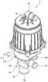
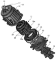
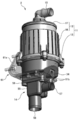
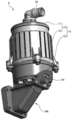
- the oil separator 2 includes a housing 11 having a lower case 12 and an upper case 13. Various components such as the rotor unit 21 and the PCV valve 24 are accommodated in an internal space (accommodating chamber) of the housing 11 (described later).
- the lower case 12 is a portion that divides the lower portion of the housing 11, and is constituted by a bottomed dish-like member having an open upper surface. And the side part of the lower case 12 is made into cylindrical shape, and the fitting part is provided in the upper end part. This fitting portion is fitted with the lower end portion of the upper case 13.
- a joint member 14 is detachably attached to the lower surface of the lower case 12.
- the lower case 12 and the joint member 14 are made of a casting, but may be made by molding a resin.
- the upper case 13 is a member attached to the lower case 12 from above, and divides a storage chamber in which the rotor unit 21 and the like are stored together with the lower case 12.
- An O-ring 15 (see FIG. 5) is attached to a connection portion between the upper case 13 and the lower case 12, and air tightness and liquid tightness are ensured.
- the upper case 13 includes a cylindrical main body cover 16 and a disk-shaped upper surface cover 17.
- the upper surface cover 17 is attached to the upper end portion of the main body cover 16 in an airtight state.
- a cylindrical gas discharge portion 18 is provided at the center of the top cover 17 so as to face upward.
- the gas discharge part 18 is a part for discharging the blow-by gas after processing, and the breather pipe 3 is connected via an outlet pipe 19.
- the internal structure of the oil separator 2 will be described.
- the rotor unit 21, the partition member 22, and the fixed frame 23 are accommodated in the accommodation chamber formed by the lower case 12 and the upper case 13. Further, as shown in the cross-sectional view of FIG. 5, a PCV valve 24 is attached inside the upper surface cover 17.
- the rotor unit 21 is a mechanism for separating mist-like oil contained in blow-by gas, and has a rotor 25, a spindle 26, and a spindle shaft 27 as shown in FIG.
- the rotor 25 is a part that aggregates mist-like oil by rotation and separates it from blow-by gas, and has a plurality of separation disks 28, an upper holder 29, and a lower holder 30.
- the separation disk 28 is a ring-shaped plate material that is inclined downward toward the outer peripheral side, in other words, a plate material that has been processed into a side surface shape of a truncated cone.
- the separation disk 28 of the present embodiment has a thickness of 1 mm or less and is manufactured by resin molding. These separation disks 28 are stacked in the axial direction of the spindle 26. For convenience of explanation, the separation disks 28 are drawn with an interval therebetween, but the actual interval is set to be extremely narrow (for example, less than 1 mm).
- the upper holder 29 is a member that holds a plurality of stacked separation disks 28 from above, and the lower holder 30 is also a member that holds from the lower side.
- a plurality of connecting arms 30a for connecting to the upper holder 29 are provided on the outer peripheral edge of the lower holder 30 (see FIG. 4). In the present embodiment, four connecting arms 30a are provided at intervals of 90 degrees in the circumferential direction.
- the rotor 25 has a cylindrical appearance, and the inner peripheral side is a hollow portion and penetrates in the vertical direction. A spindle 26 is inserted into the hollow portion, and the spindle 26 and the rotor 25 are coupled to each other. For this reason, the rotor 25 rotates around the axis of the spindle 26 together with the spindle 26.
- a nozzle 31 protrudes from the peripheral surface of the spindle 26 below the rotor 25.
- the nozzle 31 is a portion for injecting oil supplied through the spindle shaft 27 and generates a driving force for rotating the spindle 26 and the rotor 25.
- the nozzle 31 of the present embodiment has a cylindrical nozzle body 32 whose base end is joined to the spindle 26 and whose tip is closed, and an injection hole 33 provided at the tip of the nozzle body 32. .
- the nozzle body 32 is attached at an angle of 45 degrees obliquely downward with respect to the axial direction of the spindle 26.
- Three nozzle bodies 32 are provided at intervals of 120 degrees in the circumferential direction.
- the injection hole 33 is provided on the side surface of the tip portion of the nozzle body 32. Specifically, the injection hole 33 is provided in a direction perpendicular to the axial direction of the nozzle body 32 and in a direction in which oil is injected in the horizontal direction.
- the spindle shaft 27 is a cylindrical member that serves as a bearing for the spindle 26, and supports the spindle 26 in a rotatable state.
- An oil supply path 27 a for supplying oil is formed inside the spindle shaft 27.
- the lower end portion of the spindle shaft 27 is joined to the upper end portion of the support cylinder portion 34 provided in the lower case 12.
- This support cylinder part 34 is equivalent to an oil supply part, and supplies the oil injected from the injection hole 33 to the oil supply path 27a.
- an oil supply pipe 6 c shown in FIG. 1 is connected to the support cylinder portion 34.
- the oil supplied through the oil supply pipe 6 c flows into the spindle shaft 27 after passing through the support cylinder portion 34, flows into the nozzle body 32, and is then injected from the injection hole 33.
- the injection hole 33 is provided at the tip of the nozzle body 32 in a direction in which oil is injected in the horizontal direction. And in the three nozzles 31 provided at intervals of 120 degrees, the formation positions of the injection holes 33 are aligned. For this reason, when oil is injected from each injection hole 33, the rotor 25 and the spindle 26 rotate around the spindle shaft 27.
- the partition member 22 partitions the internal space (storage chamber) of the housing 11 into a lower storage chamber 35 (primary separation chamber) and an upper storage chamber 36 (secondary separation chamber). It is a member that forms a communication port 37 that guides the blow-by gas in the side storage chamber 35 to the upper storage chamber 36.
- the partition member 22 has an outer peripheral portion 41 and a tapered portion 42.
- the outer peripheral portion 41 is a short cylindrical portion, and a flange portion 43 projects laterally in the middle in the height direction.
- the tapered portion 42 is provided on the inner peripheral side with respect to the outer peripheral portion 41, and has a tapered shape that is gradually reduced in diameter from the lower end of the outer peripheral portion 41 upward.
- the tapered portion 42 of the present embodiment has an inclined surface that is inclined downward toward the outer peripheral side. The upper end opening of the tapered portion 42 forms the communication port 37.
- the partition member 22 is fitted into the fitting portion of the lower case 12 from the inner peripheral side. Then, the collar portion 43 is positioned in contact with the upper end of the fitting portion from above. As a result, the tapered portion 42 is disposed immediately below the lower holder 30 included in the rotor 25. With the partition member 22 as a boundary, the storage chamber is partitioned into a lower storage chamber 35 and an upper storage chamber 36, and the lower storage chamber 35 and the upper storage chamber 36 are communicated with each other through a communication port 37.
- the rotor 25 rotates at high speed
- an oil film that rotates at high speed is formed on the outer peripheral side from the orbit of the injection hole 33.
- the mist-like oil contained in the blow-by gas is taken into the oil film and centrifuged. Thereby, content of the mist-like oil in blow-by gas can be reduced.
- the lower storage chamber 35 functions as a primary separation chamber for mist oil.
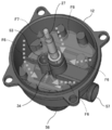
- the PCV valve 24 includes a diaphragm 45, an upper spring 46, and a lower spring 47.
- the diaphragm 45 is a valve body, and is constituted by a disk-shaped member produced by molding rubber and resin.
- the upper spring 46 and the lower spring 47 are members for supporting the diaphragm 45 in a state in which the diaphragm 45 can move in the vertical direction.
- the PCV valve 24 is disposed at a position directly below the top cover 17 in a state of being placed on the pedestal. This pedestal is airtightly covered with a diaphragm 45. A space defined by the pedestal portion and the diaphragm 45 is opened to the atmosphere through the air communication portion.
- the diaphragm 45 moves up and down according to the intake side pressure of the engine 4 and the internal pressure of the crankcase, and adjusts the flow of blow-by gas. That is, the diaphragm 45 moves to the gas discharge unit 18 side (upward) when the intake pressure (negative pressure) of the engine 4 is excessively large, and to the opposite side (downward) when the crankcase side pressure is high. Moving.
- the diaphragm 45 moves downward to increase the flow rate of blow-by gas.
- the diaphragm 45 moves upward to reduce the flow rate of blow-by gas.
- the pedestal portion on which the PCV valve 24 is placed is partitioned by a side wall portion whose outer periphery is circular in plan view, and a communication window portion 48 is provided on the side wall portion.
- a communication window portion 48 a portion above the diaphragm 45 in the upper storage chamber 36 and a portion on the rotor 25 side communicate with each other.
- a cylindrical rib 49 is provided below the side wall.
- the cylindrical rib 49 is a ring-shaped protrusion provided integrally with the main body cover 16 at a height above the rotor unit 21 and below the diaphragm 45.
- the cylindrical rib 49 guides fluid (oil or blow-by gas) flowing downward from the outer peripheral side to the inner peripheral side along the inner surface of the main body cover 16 at the upper end portion of the main body cover 16. Since the amount of oil can also be reduced by the cylindrical rib 49, oil adhesion to the PCV valve 24 can be suppressed at a high level.
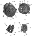
- the lower case 12 has a disc-shaped bottom 51, and a cylindrical side 52 is raised from the outer peripheral edge of the bottom 51.
- an outlet side portion of the support cylinder portion 34 which is an oil discharge side is erected upward.
- the fixed frame 23 is a metal frame (see FIG. 4), and is provided to increase the rigidity of the support cylinder portion 34.
- the inlet side portion of the support cylinder portion 34 on the oil inflow side extends sideways along the bottom portion 51, and the end portion of the inlet side portion.
- the side of the lower case 12 is open to the outside.
- a gas communication portion 53 is provided along the outlet side portion of the support tube portion 34.
- the gas communication portion 53 introduces blow-by gas from the inside of the joint member 14 to the inside of the lower case 12.
- the gas communication portion 53 of the present embodiment is constituted by a cylindrical portion that penetrates the bottom portion 51 of the lower case 12 and projects upward.
- the upper end (gas outlet) of the gas communication portion 53 is positioned on the inner peripheral side with respect to the locus of the injection hole 33 of the nozzle 31.
- the bottom case 51 of the lower case 12 is provided with an oil communication portion 54 for discharging oil.
- the oil communication portion 54 is an opening that penetrates the bottom portion 51 of the lower case 12 in the thickness direction. In the present embodiment, the oil communication portion 54 is provided at a position surrounding the support cylinder portion 34 and the gas communication portion 53. Yes.
- the joint member 14 is a member that is attached to the bottom 51 of the lower case 12 from below, and has a joint body 55, an attachment flange 56, a gas introduction part 57, and an oil discharge part 58.
- the joint body 55 is configured as a rectangular parallelepiped hollow member having an open upper surface, and the internal space functions as a common chamber.
- the attachment flange 56 is a portion used when the joint member 14 is attached to the lower case 12, and is configured by a plate-like portion that protrudes laterally from the upper end of the joint body 55. Each of the four corners of the mounting flange 56 is provided with a screw opening.
- the joint male member 14 is attached to the lower case 12 by inserting a fixed male screw into each screw opening and tightening into a female screw portion formed on the bottom 51 of the lower case 12.
- a rectangular ring-shaped packing 59 is attached between the joint member 14 and the lower case 12 to ensure liquid tightness.
- the gas introduction part 57 is a part for introducing blow-by gas introduced through the gas introduction pipe 6 a into the oil separator 2.
- the gas introduction part 57 is a cylindrical member that protrudes laterally from the side wall of the joint body 55, and communicates with the internal space 55 a (common chamber) of the joint body 55 from the side. And the edge part of the gas introduction pipe 6a is connected to a protrusion part.
- the oil discharge part 58 is a part for discharging the oil flowing down from the oil communication part 54 of the lower case 12 toward the engine 4.
- the oil discharge portion 58 is a cylindrical member that protrudes downward from the bottom portion 51 of the joint main body 55, and communicates with the internal space 55 a of the joint main body 55 from below. And the edge part of the oil discharge pipe 6b is connected to a protrusion part.
- FIG. 7 is a view of the lower case 12 to which the joint member 14 is attached as seen from the plane direction. As shown in FIG. 7, when the joint member 14 is attached, the oil discharge portion 58 is located directly below the oil communication portion 54. As a result, the oil flowing down from the oil communication portion 54 is smoothly discharged from the oil discharge portion 58.
- the oil supplied to the support cylinder portion 34 flows into the spindle shaft 27 as indicated by the path F1.
- the oil flows from the spindle shaft 27 into the nozzle body 32 and is ejected from the ejection hole 33.
- the rotor 25 and the spindle 26 rotate around the spindle shaft 27.
- the oil injected from each injection hole 33 moves along the path of the symbol F2. That is, the sprayed oil is sprayed onto the tapered portion 42 of the partition member 22 and guided along the inclined surface of the tapered portion 42 in an obliquely downward direction on the outer peripheral side. Thereby, mixing of the oil splash into the blow-by gas is suppressed. Thereafter, the oil flows down the inner surface of the lower case 12 and flows into the internal space 55 a of the joint member 14 from the oil communication portion 54. Further, the oil flows into the oil discharge part 58 and returns to the engine 4 through the oil discharge pipe 6b.
- the blow-by gas introduced from the engine 4 through the gas introduction pipe 6a moves along the path indicated by the arrow F3. That is, the blow-by gas flows into the gas introduction part 57 of the joint member 14.
- the blow-by gas that has passed through the gas introduction part 57 flows into the gas communication part 53 from the internal space 55 a of the joint body 55.
- the blow-by gas that has passed through the gas communication portion 53 flows into the hollow portion of the rotor 25 through the inside of the movement locus of the injection hole 33.
- blow-by gas that has flowed into the hollow portion of the rotor 25 moves through the gap between the separation disks 28 toward the outer periphery of the rotor 25 due to the centrifugal force generated as the rotor 25 rotates.
- the pressure on the inner circumferential side of the rotor 25 becomes lower than the pressure on the outer circumferential side. Due to this pressure difference, the blow-by gas that has passed through the gas communication portion 53 is likely to flow into the hollow portion of the rotor 25, so that the inflow efficiency of the blow-by gas can be increased.
- the blow-by gas comes into contact with the separation disk 28, mist oil contained in the blow-by gas adheres to the surface of the separation disk 28. Then, another mist-like oil is combined with the attached mist-like oil, and the oil is aggregated on the surface of the separation disk 28. That is, the oil is secondarily separated. As described above, the blow-by gas is primarily separated from the mist-like oil in the lower housing chamber 35. For this reason, the mist oil is separated from the blow-by gas at a high level by the secondary separation at the separation disk 28.
- the upper storage chamber 36 corresponds to a secondary separation chamber for secondary separation of the remaining mist-like oil with respect to the blow-by gas after the mist-like oil is primarily separated.
- a gap SP is formed between the spindle 26 and the spindle shaft 27.
- This gap SP functions as an oil guide path and is filled with oil supplied to be ejected from the nozzle 31.
- the supply pressure of the oil is sufficiently high, a part of the oil filled in the gap is discharged from the upper end portion of the spindle 26 to the hollow portion of the rotor 25 through the upper end of the gap. Then, the oil released into the hollow portion of the rotor 25 moves in the gap between the separation disks 28 in the outer circumferential direction of the rotor 25 by the centrifugal force of the rotor 25 as in the blow-by gas.
- the oil aggregated on the surface of the separation disk 28 is combined with the oil discharged into the hollow portion of the rotor 25. As a result, the surface of the separation disk 28 is cleaned, and maintenance for the separation disk 28 can be simplified.
- the oil agglomerated or coalesced on the surface of the separation disk 28 moves along a path indicated by reference numeral F4 in FIG. That is, these oils are discharged from the outer peripheral edge of the separation disk 28, collide with the inner surface of the main body cover 16, and then flow down the inner surface. Further, the oil merges with the oil injected from the nozzle 31 in the lower case 12, and returns to the engine 4 through the oil communication portion 54, the oil discharge portion 58, and the oil discharge pipe 6b.
- blow-by gas from which the mist-like oil has been separated after passing through the rotor 25 moves along a path indicated by reference numeral F5 in FIG. That is, the blow-by gas that has passed through the rotor 25 rises in the upper case 13 as a swirling flow and is guided to the upper surface side space of the PCV valve 24. Thereafter, it is guided to the breather pipe 3 through the outlet pipe 19.
- the oil communication portion 54 and the gas communication portion 53 are communicated with the upper portion of the internal space 55a (common chamber) of the joint body 55.
- the gas introduction part 57 communicates with the internal space 55a of the joint body 55 from the side, and the oil discharge part 58 communicates with the internal space 55a of the joint body 55 from below. Therefore, the blow-by gas introduced from the gas introduction part 57 comes into contact with the oil flowing down from the oil communication part 54 in the internal space 55a of the joint body 55. Thereby, a part of the oil mist contained in the blow-by gas is taken into the oil, and the oil removal efficiency with respect to the blow-by gas can be enhanced.
- the oil communication portion 54 is formed in the bottom portion 51 of the lower case 12 and is configured by a through-opening that penetrates the plate thickness direction.
- the gas communication portion 53 is located above the bottom portion 51 of the lower case 12. It is comprised by the cylindrical part protruded toward. That is, a blow-by gas passage extending in the vertical direction is defined by the cylindrical portion constituting the gas communication portion 53.
- the gas outlet of the gas communication portion 53 is disposed on the inner peripheral side with respect to the locus of the injection hole 33, the blow-by gas can be efficiently introduced into the hollow portion of the rotor 25.
- the bracket 61 illustrated in FIG. 10 has a mounting base 61a and a fork portion 61b.
- the attachment base 61a is a part attached to the engine 4 and is constituted by a trapezoidal metal plate.
- the fork portion 61b is two elongate plate-like portions extending in a direction orthogonal to the mounting base 61a from both lower ends of the mounting base 61a.
- Each of the mounting base 61a and the fork portion 61b is provided with a plurality of screw holes.
- the fixing base 61 a is attached to the side surface of the engine 4 and the fork portion 61 b is fixed to the bottom surface of the lower case 12 by inserting and fastening the fixing screw into the screw hole.
- the mounting position of the bracket 61 can be brought close to the center of gravity of the rotating body (separation disk 28, nozzle 31, spindle 26), and vibration and rattling of the oil separator 2 can be suppressed.
- the oil separator 2 can be attached to an attachment object other than the engine 4.
- the oil separator 2 can be attached to the vehicle body.
- the first modification shown in FIG. 11 is different from the above-described embodiment in that the gas introduction part 57 included in the joint member 14 is configured by an elbow member.
- the gas introduction part 57 is constituted by an elbow member that can swing, even if there is a restriction on the arrangement of the gas introduction pipe 6a for introducing the blow-by gas, it can be handled relatively easily.
- the second modification shown in FIG. 12 is different from the above-described embodiment in that flanges 57a and 58a are provided in the gas introduction part 57 and the oil discharge part 58.
- the flanges 57a and 58a are provided in the gas introduction part 57 and the oil discharge part 58, respectively, it is easily connected to the gas introduction pipe 6a and the oil discharge pipe 6b provided with the flange. it can.
- the gas introduction part 57 and the oil discharge part 58 are provided in the joint part. Since it is detachably attached to the lower case 12, the joint members 14 and 14 ⁇ / b> A may be prepared according to the vehicle model to be attached, and can be easily attached to various attachment objects. In addition, since other parts can be made common parts, mass production is possible and cost can be reduced.
- SYMBOLS 1 Closed-type crankcase ventilation system, 2 ... Oil separator, 3 ... Breather pipe, 4 ... Engine, 5 ... Intake side flow path, 6a ... Gas introduction pipe, 6b ... Oil discharge pipe, 6c ... Oil supply pipe, 7 ... Air filter, 8 ... Turbocharger, 9 ... Charge cooler, 11 ... Housing, 12 ... Lower case, 13 ... Upper case, 14 ... Joint member, 14A ... Joint member of third modification, 15 ... O-ring, 16 ... Main body cover, 17 ... upper surface cover, 18 ... gas discharge part, 19 ... outlet pipe, 21 ... rotor unit, 22 ... partition member, 23 ... fixed frame, 24 ... PCV valve, 25 ...
- a gas communication part of the lower case 54 ... an oil communication part of the lower case, 55 ... a joint body of the joint member, 55a ... an internal space of the joint body ( Common chamber), 56 ... Joint flange of the joint member, 57 ... Gas introduction part of the joint member, 58 ... Oil discharge part of the joint member, 59 ... Packing, 61 ... Bracket, 61 ... mounting base, 61b ... fork portion
Landscapes
- Engineering & Computer Science (AREA)
- Chemical & Material Sciences (AREA)
- Chemical Kinetics & Catalysis (AREA)
- Mechanical Engineering (AREA)
- General Engineering & Computer Science (AREA)
- Lubrication Details And Ventilation Of Internal Combustion Engines (AREA)
- Separating Particles In Gases By Inertia (AREA)
- Centrifugal Separators (AREA)
Abstract
Description
Claims (5)
- 処理対象ガスに含まれるミスト状オイルを分離するオイルセパレータであって、
スピンドルと共に回転可能に設けられ、回転によって前記ミスト状オイルを分離するローターと、
前記スピンドルにおける前記ローターよりも下側の周面から突設され、噴射孔からオイルを噴射させることで軸線を中心に前記スピンドルを回転させるノズルと、
前記噴射孔から噴射されるオイルを供給するオイル供給部、前記噴射孔から噴射されたオイルを排出するためのオイル用連通部、及び前記処理対象ガスを導入するためのガス用連通部が設けられたハウジングと、
外部からの前記処理対象ガスを導入して前記ガス用連通部へ送出するガス導入部、及び前記オイル用連通部からのオイルを受け入れて外部へ排出させるオイル排出部が設けられ、前記ハウジングへ着脱可能に取り付けられたジョイント部材を有することを特徴とするオイルセパレータ。 - 前記ジョイント部材は、前記オイル用連通部、前記ガス用連通部、前記ガス導入部、及び前記オイル排出部のそれぞれに連通された共通チャンバーを有し、
前記オイル用連通部及び前記ガス用連通部は、前記共通チャンバーの上部に連通され、
前記ガス導入部は、前記共通チャンバーの側部に連通され、
前記オイル排出部は、前記共通チャンバーの下部に連通されていることを特徴とする請求項1に記載のオイルセパレータ。 - 前記オイル用連通部は、前記ハウジングの底部に形成され、板厚方向を貫通する貫通開口によって構成され、
前記ガス用連通部は、前記ハウジングの底部から上方に向けて突設された筒状部によって構成されていることを特徴とする請求項1又は2に記載のオイルセパレータ。 - 前記ガス用連通部のガス出口は、前記噴射孔の軌跡よりも内周側に開口していることを特徴とする請求項3に記載のオイルセパレータ。
- 前記ハウジングに装着され、支持体への取り付け部となるブラケットを有することを特徴とする請求項1から4の何れか1項に記載のオイルセパレータ。
Priority Applications (4)
| Application Number | Priority Date | Filing Date | Title |
|---|---|---|---|
| US15/121,674 US10569206B2 (en) | 2014-02-26 | 2014-02-06 | Oil separator |
| PCT/JP2014/054630 WO2015128953A1 (ja) | 2014-02-26 | 2014-02-26 | オイルセパレータ |
| JP2016504902A JP6336038B2 (ja) | 2014-02-26 | 2014-02-26 | オイルセパレータ |
| EP14884204.0A EP3112033B1 (en) | 2014-02-26 | 2014-02-26 | Oil separator |
Applications Claiming Priority (1)
| Application Number | Priority Date | Filing Date | Title |
|---|---|---|---|
| PCT/JP2014/054630 WO2015128953A1 (ja) | 2014-02-26 | 2014-02-26 | オイルセパレータ |
Publications (1)
| Publication Number | Publication Date |
|---|---|
| WO2015128953A1 true WO2015128953A1 (ja) | 2015-09-03 |
Family
ID=54008325
Family Applications (1)
| Application Number | Title | Priority Date | Filing Date |
|---|---|---|---|
| PCT/JP2014/054630 Ceased WO2015128953A1 (ja) | 2014-02-26 | 2014-02-26 | オイルセパレータ |
Country Status (4)
| Country | Link |
|---|---|
| US (1) | US10569206B2 (ja) |
| EP (1) | EP3112033B1 (ja) |
| JP (1) | JP6336038B2 (ja) |
| WO (1) | WO2015128953A1 (ja) |
Families Citing this family (2)
| Publication number | Priority date | Publication date | Assignee | Title |
|---|---|---|---|---|
| CN108883424B (zh) * | 2016-04-06 | 2020-12-15 | 东京滤器株式会社 | 油分离器 |
| EP4335551A1 (en) * | 2022-09-09 | 2024-03-13 | Alfdex AB | A centrifugal separator for cleaning gas |
Citations (7)
| Publication number | Priority date | Publication date | Assignee | Title |
|---|---|---|---|---|
| JPS5176868A (ja) * | 1974-12-27 | 1976-07-03 | Hitachi Ltd | Itsusoshikidatsusuisentakuki |
| JP2003184528A (ja) * | 2001-12-21 | 2003-07-03 | Fuji Heavy Ind Ltd | オイルフィルタ装置 |
| JP2005507310A (ja) * | 2001-11-01 | 2005-03-17 | アルファ ラヴァル コーポレイト アクチボラゲット | 液体と気体とを同時に浄化する装置 |
| JP2005515065A (ja) * | 2002-01-25 | 2005-05-26 | アルファ ラヴァル コーポレイト アクチボラゲット | 液体とガスとを同時に浄化する装置 |
| JP2008502473A (ja) * | 2004-06-16 | 2008-01-31 | 3ニーネ アクチボラゲット | 遠心分離機のローターユニット |
| JP2009167812A (ja) * | 2008-01-10 | 2009-07-30 | Toyota Boshoku Corp | 遠心分離式オイルフィルタ |
| JP2011528280A (ja) * | 2008-07-16 | 2011-11-17 | アルファ ラヴァル コーポレイト アクチボラゲット | 遠心分離機 |
Family Cites Families (23)
| Publication number | Priority date | Publication date | Assignee | Title |
|---|---|---|---|---|
| BE624585A (ja) * | 1961-11-22 | |||
| US6183407B1 (en) * | 1998-04-02 | 2001-02-06 | Alfa Laval Ab | Centrifugal separator having axially-extending, angled separation discs |
| US6110246A (en) * | 1998-07-23 | 2000-08-29 | Dreison International, Inc. | Air precleaner having stationary vanes and rotating impeller |
| US6017300A (en) * | 1998-08-19 | 2000-01-25 | Fleetguard, Inc. | High performance soot removing centrifuge with impulse turbine |
| SE515302C2 (sv) * | 1999-11-15 | 2001-07-09 | Alfa Laval Ab | Ett sätt och en apparat för rening av gas |
| SE517663C2 (sv) * | 2000-10-27 | 2002-07-02 | Alfa Laval Corp Ab | Centrifugalseparator för rening av ett gasformigt fluidum |
| DE10063903A1 (de) * | 2000-12-21 | 2002-07-04 | Mann & Hummel Filter | Freistrahlzentrifuge mit integriertem Ölabscheider |
| SE0201982D0 (sv) * | 2002-06-24 | 2002-06-24 | Alfa Laval Corp Ab | Sätt att rena vevhusgas samt en gasreningsseparator |
| SE523676C2 (sv) * | 2002-09-04 | 2004-05-11 | Alfa Laval Corp Ab | Apparat för rening av gas |
| US7235177B2 (en) * | 2003-04-23 | 2007-06-26 | Fleetguard, Inc. | Integral air/oil coalescer for a centrifuge |
| US8177967B2 (en) * | 2004-02-16 | 2012-05-15 | Cummins Filtration Ip, Inc. | Spin-on filter with performance enhancement features |
| US7258713B2 (en) * | 2004-08-27 | 2007-08-21 | Dreison International, Inc. | Inlet vane for centrifugal particle separator |
| SE529609C2 (sv) * | 2006-02-13 | 2007-10-02 | Alfa Laval Corp Ab | Centrifugalseparator |
| SE529611C2 (sv) * | 2006-02-13 | 2007-10-02 | Alfa Laval Corp Ab | Centrifugalseparator |
| US7338546B2 (en) * | 2006-04-19 | 2008-03-04 | Alfa Laval Corporate Ab | Centrifugal separator for cleaning gas generated by an internal combustion engine and a method for operating the same |
| SE530223C2 (sv) * | 2006-05-15 | 2008-04-01 | Alfa Laval Corp Ab | Centrifugalseparator |
| DE202007009913U1 (de) * | 2007-07-13 | 2008-11-20 | Hengst Gmbh & Co.Kg | Abscheider zum Abscheiden von Ölnebel aus dem Kurbelgehäuseentlüftungsgas einer Brennkraftmaschine und Brennkraftmaschine mit einem Abscheider |
| DE202008014734U1 (de) * | 2008-11-06 | 2010-03-25 | Hengst Gmbh & Co.Kg | Zentrifugalabscheider |
| US20110011795A1 (en) * | 2009-07-15 | 2011-01-20 | Hoff William D | Fluid pressure driven centrifuge apparatus |
| DE102011076465B4 (de) * | 2011-05-25 | 2021-04-29 | Hengst Se | Zentrifugalabscheider zum Abscheiden von Ölnebel aus dem Kurbelgehäuseentlüftungsgas einer Brennkraftmaschine |
| US9987579B2 (en) * | 2013-03-28 | 2018-06-05 | Tokyo Roki Co., Ltd. | Oil separator |
| EP2944391A1 (en) * | 2014-05-13 | 2015-11-18 | Alfa Laval Corporate AB | Centrifugal separator |
| US10513955B2 (en) * | 2015-06-19 | 2019-12-24 | Tokyo Roki Co., Ltd. | Oil separator |
-
2014
- 2014-02-06 US US15/121,674 patent/US10569206B2/en active Active
- 2014-02-26 WO PCT/JP2014/054630 patent/WO2015128953A1/ja not_active Ceased
- 2014-02-26 EP EP14884204.0A patent/EP3112033B1/en active Active
- 2014-02-26 JP JP2016504902A patent/JP6336038B2/ja active Active
Patent Citations (7)
| Publication number | Priority date | Publication date | Assignee | Title |
|---|---|---|---|---|
| JPS5176868A (ja) * | 1974-12-27 | 1976-07-03 | Hitachi Ltd | Itsusoshikidatsusuisentakuki |
| JP2005507310A (ja) * | 2001-11-01 | 2005-03-17 | アルファ ラヴァル コーポレイト アクチボラゲット | 液体と気体とを同時に浄化する装置 |
| JP2003184528A (ja) * | 2001-12-21 | 2003-07-03 | Fuji Heavy Ind Ltd | オイルフィルタ装置 |
| JP2005515065A (ja) * | 2002-01-25 | 2005-05-26 | アルファ ラヴァル コーポレイト アクチボラゲット | 液体とガスとを同時に浄化する装置 |
| JP2008502473A (ja) * | 2004-06-16 | 2008-01-31 | 3ニーネ アクチボラゲット | 遠心分離機のローターユニット |
| JP2009167812A (ja) * | 2008-01-10 | 2009-07-30 | Toyota Boshoku Corp | 遠心分離式オイルフィルタ |
| JP2011528280A (ja) * | 2008-07-16 | 2011-11-17 | アルファ ラヴァル コーポレイト アクチボラゲット | 遠心分離機 |
Non-Patent Citations (1)
| Title |
|---|
| See also references of EP3112033A4 * |
Also Published As
| Publication number | Publication date |
|---|---|
| JPWO2015128953A1 (ja) | 2017-03-30 |
| US10569206B2 (en) | 2020-02-25 |
| JP6336038B2 (ja) | 2018-06-06 |
| EP3112033A4 (en) | 2018-01-17 |
| EP3112033B1 (en) | 2025-04-23 |
| US20160375388A1 (en) | 2016-12-29 |
| EP3112033A1 (en) | 2017-01-04 |
Similar Documents
| Publication | Publication Date | Title |
|---|---|---|
| JP6286530B2 (ja) | オイルセパレータ | |
| JP6069488B2 (ja) | オイルセパレータ | |
| JP6268302B2 (ja) | オイルセパレータ | |
| JP6255476B2 (ja) | オイルセパレータ | |
| JP6511522B2 (ja) | オイルセパレータ | |
| JP6336037B2 (ja) | オイルセパレータ | |
| CN107427846B (zh) | 油分离器 | |
| WO2014155614A1 (ja) | オイルセパレータ | |
| JP6336038B2 (ja) | オイルセパレータ | |
| WO2016139716A1 (ja) | 分離ディスク及びオイルセパレータ | |
| JP6322715B2 (ja) | ミスト状オイルの分離方法、及び、オイルセパレータ |
Legal Events
| Date | Code | Title | Description |
|---|---|---|---|
| 121 | Ep: the epo has been informed by wipo that ep was designated in this application |
Ref document number: 14884204 Country of ref document: EP Kind code of ref document: A1 |
|
| ENP | Entry into the national phase |
Ref document number: 2016504902 Country of ref document: JP Kind code of ref document: A |
|
| NENP | Non-entry into the national phase |
Ref country code: DE |
|
| WWE | Wipo information: entry into national phase |
Ref document number: 15121674 Country of ref document: US |
|
| REEP | Request for entry into the european phase |
Ref document number: 2014884204 Country of ref document: EP |
|
| WWE | Wipo information: entry into national phase |
Ref document number: 2014884204 Country of ref document: EP |
|
| WWG | Wipo information: grant in national office |
Ref document number: 2014884204 Country of ref document: EP |