WO2015128954A1 - デバイス情報提供システム、デバイス情報提供方法 - Google Patents
デバイス情報提供システム、デバイス情報提供方法 Download PDFInfo
- Publication number
- WO2015128954A1 WO2015128954A1 PCT/JP2014/054632 JP2014054632W WO2015128954A1 WO 2015128954 A1 WO2015128954 A1 WO 2015128954A1 JP 2014054632 W JP2014054632 W JP 2014054632W WO 2015128954 A1 WO2015128954 A1 WO 2015128954A1
- Authority
- WO
- WIPO (PCT)
- Prior art keywords
- processing module
- output
- virtual
- requirement
- extracted
- Prior art date
- Legal status (The legal status is an assumption and is not a legal conclusion. Google has not performed a legal analysis and makes no representation as to the accuracy of the status listed.)
- Ceased
Links
Images



Classifications
-
- G—PHYSICS
- G06—COMPUTING OR CALCULATING; COUNTING
- G06F—ELECTRIC DIGITAL DATA PROCESSING
- G06F16/00—Information retrieval; Database structures therefor; File system structures therefor
- G06F16/20—Information retrieval; Database structures therefor; File system structures therefor of structured data, e.g. relational data
- G06F16/25—Integrating or interfacing systems involving database management systems
- G06F16/252—Integrating or interfacing systems involving database management systems between a Database Management System and a front-end application
-
- H—ELECTRICITY
- H04—ELECTRIC COMMUNICATION TECHNIQUE
- H04W—WIRELESS COMMUNICATION NETWORKS
- H04W4/00—Services specially adapted for wireless communication networks; Facilities therefor
- H04W4/70—Services for machine-to-machine communication [M2M] or machine type communication [MTC]
-
- G—PHYSICS
- G06—COMPUTING OR CALCULATING; COUNTING
- G06F—ELECTRIC DIGITAL DATA PROCESSING
- G06F16/00—Information retrieval; Database structures therefor; File system structures therefor
- G06F16/20—Information retrieval; Database structures therefor; File system structures therefor of structured data, e.g. relational data
- G06F16/24—Querying
- G06F16/248—Presentation of query results
-
- G—PHYSICS
- G06—COMPUTING OR CALCULATING; COUNTING
- G06F—ELECTRIC DIGITAL DATA PROCESSING
- G06F16/00—Information retrieval; Database structures therefor; File system structures therefor
- G06F16/30—Information retrieval; Database structures therefor; File system structures therefor of unstructured textual data
- G06F16/33—Querying
- G06F16/338—Presentation of query results
-
- G—PHYSICS
- G06—COMPUTING OR CALCULATING; COUNTING
- G06F—ELECTRIC DIGITAL DATA PROCESSING
- G06F16/00—Information retrieval; Database structures therefor; File system structures therefor
- G06F16/90—Details of database functions independent of the retrieved data types
- G06F16/95—Retrieval from the web
- G06F16/951—Indexing; Web crawling techniques
-
- G—PHYSICS
- G06—COMPUTING OR CALCULATING; COUNTING
- G06F—ELECTRIC DIGITAL DATA PROCESSING
- G06F16/00—Information retrieval; Database structures therefor; File system structures therefor
- G06F16/90—Details of database functions independent of the retrieved data types
- G06F16/95—Retrieval from the web
- G06F16/953—Querying, e.g. by the use of web search engines
- G06F16/9535—Search customisation based on user profiles and personalisation
-
- G—PHYSICS
- G06—COMPUTING OR CALCULATING; COUNTING
- G06F—ELECTRIC DIGITAL DATA PROCESSING
- G06F16/00—Information retrieval; Database structures therefor; File system structures therefor
- G06F16/90—Details of database functions independent of the retrieved data types
- G06F16/95—Retrieval from the web
- G06F16/953—Querying, e.g. by the use of web search engines
- G06F16/9538—Presentation of query results
-
- G—PHYSICS
- G06—COMPUTING OR CALCULATING; COUNTING
- G06F—ELECTRIC DIGITAL DATA PROCESSING
- G06F9/00—Arrangements for program control, e.g. control units
- G06F9/06—Arrangements for program control, e.g. control units using stored programs, i.e. using an internal store of processing equipment to receive or retain programs
- G06F9/44—Arrangements for executing specific programs
- G06F9/455—Emulation; Interpretation; Software simulation, e.g. virtualisation or emulation of application or operating system execution engines
- G06F9/45533—Hypervisors; Virtual machine monitors
- G06F9/45558—Hypervisor-specific management and integration aspects
-
- H—ELECTRICITY
- H04—ELECTRIC COMMUNICATION TECHNIQUE
- H04L—TRANSMISSION OF DIGITAL INFORMATION, e.g. TELEGRAPHIC COMMUNICATION
- H04L67/00—Network arrangements or protocols for supporting network services or applications
- H04L67/01—Protocols
- H04L67/12—Protocols specially adapted for proprietary or special-purpose networking environments, e.g. medical networks, sensor networks, networks in vehicles or remote metering networks
-
- G—PHYSICS
- G06—COMPUTING OR CALCULATING; COUNTING
- G06F—ELECTRIC DIGITAL DATA PROCESSING
- G06F9/00—Arrangements for program control, e.g. control units
- G06F9/06—Arrangements for program control, e.g. control units using stored programs, i.e. using an internal store of processing equipment to receive or retain programs
- G06F9/44—Arrangements for executing specific programs
- G06F9/455—Emulation; Interpretation; Software simulation, e.g. virtualisation or emulation of application or operating system execution engines
- G06F9/45533—Hypervisors; Virtual machine monitors
- G06F9/45558—Hypervisor-specific management and integration aspects
- G06F2009/45595—Network integration; Enabling network access in virtual machine instances
Definitions
- the present invention relates to a technique for making it possible to easily search for a device that matches a purpose from a large number of devices in various places.
- the sensor network is a technology that enables collection, management, and seamless use of sensing data by installing sensor devices having a detection function and a communication function in various places and networking them. If a sensor network is realized, it will be easy to quickly and accurately grasp the situation of every place from anywhere, so it can be applied to industrial fields such as manufacturing sites and logistics, as well as social systems such as transportation and various infrastructures. It is expected to have a wide range of applications in fields related to life such as medicine and education.
- sensor networks have the advantage that as the number and types of sensors increase, the overall system capabilities (resolution, wide area of support, types of sensing data that can be acquired, etc.) increase. If the amount is too large, it will be difficult to find an optimal sensor for obtaining the target information, and there is a concern that the convenience may be reduced.
- a method is proposed in which a sensor management system accepts a user's sensor request, searches for a sensor service corresponding to the sensor request, and provides it to the user. Has been.
- the present inventors are paying attention to a technology called “virtual sensor” as one of the possibilities of the sensor network.
- the virtual sensor is a sensor that analyzes and processes sensing data obtained from another sensor and outputs it as new sensing data. That is, the substance of the virtual sensor is a combination of one or a plurality of real sensors and a program module that performs data processing. By encapsulating them as virtual sensors and providing them to the sensor network user, the user can use the virtual sensor without distinction from the actual sensor. By introducing such virtual sensors, various effects can be expected, such as improving the utilization rate of resources (actual sensors) and providing sensing data with new added value.
- the same problem may occur in the case of an actuator (controller) network.
- Sensors and “actuators (controllers)” have some difference in whether they “detect (acquire) the state” or “change the state”, but they perform some action on the target area within a predetermined range. The point is common.
- the term “device” is used as a concept including “sensor” and “actuator”. Note that a virtual actuator means a combination of outputs from a plurality of actual actuators that creates new added value.
- the present invention has been made in view of the above circumstances, and an object of the present invention is to automatically generate a virtual device in response to a user request, thereby providing information on a device that satisfies the user request.
- the aim is to provide technology to expand the possibilities.
- the present invention adopts the following configuration. That is, the device information providing system according to the present invention includes a search request receiving means for receiving a search request including an output requirement for specifying a desired output result as a search request for searching for a device, and one or more other search requests.
- the information about the processing module that takes the output from the device as an input and generates a new output by combining these inputs, at least the input requirements for specifying the input of the processing module, and the output of the processing module A processing module DB registered for a plurality of processing modules together with output requirements for the device, a device DB registered for a plurality of devices together with output requirements for specifying the output of the device at least, and the search request.
- Processing module extraction means for extracting a processing module that can acquire the desired output result specified in the search request from the processing module DB, input requirements for the extracted processing module, and each device By comparing with the output requirement, one or more devices having an output usable as input of the extracted processing module are extracted from the device DB, and the extracted one or more devices and the extracted are extracted.
- Virtual device generation means for generating a virtual device comprising a combination of processing modules; and device information provision means for providing information on the virtual device generated by the virtual device generation means to a user as a search result
- a processing module that can acquire a user-desired output result and a device that has an output that can be used as an input of the processing module are automatically selected based on a user search request, and a virtual device is selected. Generated automatically. Therefore, even if there is no device that matches the user's request (not registered in the search database in advance), it is possible to meet the user's request by creating a new virtual device. Effective use of network resources and increase of usage opportunities by users can be achieved.
- the system extracts, from the device DB, devices that can obtain the desired output result specified in the search request by comparing the output requirements included in the search request with the output requirements of each device. It is preferable that the device information providing unit further includes device information extracted by the device extracting unit as a search result. Thereby, both the information on the existing device registered in the device DB and the information on the new virtual device generated by the virtual device generation unit can be provided to the user. For the user, it is possible to search for existing devices and virtual devices without distinction, and convenience is improved. Furthermore, rationalization of the system configuration can be expected by utilizing the device DB as a database for searching for existing devices.
- the device extraction process by the device extraction unit is performed preferentially over the processing module extraction process by the processing module extraction unit and the virtual device generation process by the virtual device generation unit. Since the virtual device uses the output of another device, there are cases in which the use cost is high, the processing load is large, or the accuracy is reduced due to data processing, as compared with the existing device. Therefore, if there is an existing device that satisfies the user's request, it is more appropriate to preferentially provide information about the existing device. In addition, by performing device extraction processing that is lighter than processing module extraction processing and virtual device generation processing first, the time required to provide search results to the user can be reduced, and high-speed search can be performed. There is also an advantage that it can be realized.
- the processing module extraction processing by the processing module extraction means and the virtual device generation processing by the virtual device generation means may be performed.
- “The case where the predetermined condition is not reached” is, for example, a case where no device is extracted, or a case where the number of extracted devices is less than a predetermined number. According to this configuration, when the existing device extraction result is sufficient, the processing module extraction processing and the virtual device generation processing are not executed, so that the processing load on the system can be reduced.
- the device DB includes a real device DB in which information on physical devices that physically exist is registered, and a virtual device DB in which information on virtual devices is registered.
- the device is searched from the three categories of the existing real device registered in the real device DB, the existing virtual device registered in the virtual device DB, and the newly generated virtual device. It is possible to further expand the possibility of providing information on devices that meet the requirements.
- the virtual device generation means includes a device having an output that can be used as an input of the extracted processing module, among a real device registered in the real device DB and a virtual device registered in the virtual device DB. It is preferable to extract from. This makes it possible to use an existing virtual device as an input for a new virtual device, greatly increasing the degree of freedom in creating a virtual device. Therefore, the possibility of generating a virtual device that matches the user's request can be further expanded.
- the virtual device generation means when a new virtual device is generated by the virtual device generation means, information on the new virtual device is automatically registered in the virtual device DB. If the virtual device information once generated is registered in the virtual device DB in this manner, when a similar search request is received from another user, the virtual device generation processing is not performed and only the virtual device DB search is performed. Since it is possible to cope with it, the processing load of the system can be reduced.
- the present invention can also be understood as a device information providing system having at least one of the above means, or as a device network system including a device information providing system and a plurality of devices.
- the present invention can also be understood as a device information providing method including at least one of the above processes, a program for causing a computer to execute each step of the device information providing method, and a storage medium storing the program Can also be taken as.
- the present invention by automatically generating a virtual device in response to a user request, the possibility of providing information on a device that satisfies the user request can be expanded.
- the figure which shows the structure of a device network system The figure which shows the usage example of a device search process.
- the device network system includes a device network 1 and a device management system 2.
- the device network 1 is a network constituted by a large number of devices 10 existing in various places.
- the network configuration, communication method, and the like can be arbitrarily designed and are not particularly limited.
- Each device 10 can communicate with the device management system 2 via a wide area network such as the Internet.
- the device management system 2 manages information about the devices 10 constituting the device network 1 and information collected from the devices, and provides various services for users who want to use the devices 10 (device search is one of them).
- Server device A user can access a service provided by the device management system 2 from the user terminal 3 through a wide area network such as the Internet.
- the device information providing system and the device information providing method according to the present invention are implemented as one function of the device management system 2.
- the device management system 2 has a function for registering a new device in the system and a function for changing information about the device as functions for the owner of the device.
- the device management system 2 also provides a function for creating and registering a virtual device, which will be described later, and a processing module used in the virtual device, as a function for a third party.
- a person who creates or registers a virtual device or processing module is called a “creator”.
- the device management system 2 functions to mediate between the user of the device and the owner or creator (verification / arbitration of usage conditions and provision conditions, charging to the user and the owner or creation) It is also preferable to have a consideration payment to a person.
- Each device 10 is a device that acts on a target area defined in space or space-time, and can be roughly classified into “sensor” and “actuator”.
- space is a region defined by two dimensions (x, y) or three dimensions (x, y, z)
- time space is a dimension of “time (t)” in “space”. That is, an area defined by three dimensions (x, y; t) or four dimensions (x, y, z; t).
- the term “sensor” is used to mean a device that detects (acquires) the state of the target region
- actuator is used to mean a device that changes the state of the target region.
- sensors examples include image sensors (cameras), temperature sensors, humidity sensors, illuminance sensors, force sensors, sound sensors, RFID sensors, infrared sensors, attitude sensors, rainfall sensors, radioactivity sensors, gas sensors, and the like.
- image sensors cameras
- humidity sensors humidity sensors
- illuminance sensors force sensors
- sound sensors RFID sensors
- infrared sensors attitude sensors
- rainfall sensors radioactivity sensors
- gas sensors gas sensors
- any type of sensor can be used in this system.
- actuators such as motors, solenoids, controllers, robots, lighting, speakers, displays, digital signage, and air conditioning are applicable, and any type of actuator can be used in this system.
- devices including both sensors (image sensors and the like) and actuators (display, speakers and the like) such as mobile phones, smartphones, and slate terminals.
- Various types of devices can be mixed in the device network 1.
- the device management system 2 includes a search request receiving unit 20, a DB search unit 21, a device combination reasoning unit 22, a device information providing unit 23, a physical device master DB 24, a virtual device master DB 25, as functions related to device search and information provision. It has functions such as the algorithm master DB 26.
- the device management system 2 can be configured by a computer including a CPU, a main storage device (memory), an auxiliary storage device (HDD, SSD, etc.), a communication device, an input device, a display device, and the like in hardware.
- Each functional block shown in FIG. 1 is implemented by loading a computer program stored in the auxiliary storage device into the main storage device and executing the program by the CPU.
- the device management system 2 may be configured by a single computer or a plurality of computers that cooperate.
- the user terminal 3 for example, a personal computer, a mobile phone, a smartphone, a slate type terminal, or the like can be used.
- a user searches for a device via the Internet.
- a configuration in which the user operates the device management system itself, or a part or all of the functions of the device management system is provided on the user terminal 3 side. It may be configured to be mounted.
- the device information providing service is a search service for facilitating the user to find the optimum device for achieving the purpose from among the many devices 10 constituting the device network 1.
- a specific usage example of the sensor information providing service will be described with reference to FIGS.
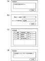
- FIG. 2 (a) When the user accesses the device information providing service using the user terminal 3, a search condition input screen as shown in FIG. 2 (a) is displayed.
- the search condition (purpose of search) can be input in free text, for example, “I want to know the weather in Kusatsu City”.
- FIG. 2B is another example of the search condition input screen.
- the desired sensing data type and sensing target area are entered in separate boxes.
- the search button is pressed, a search request is transmitted from the user terminal 3 to the device management system 2, and device search processing is executed in the device management system 2. Details of the device search process will be described later.
- FIG. 2C is an example of a search result screen returned from the device management system 2.
- two types of sensors that can acquire the weather of Kusatsu City are presented, and further, sensors that can acquire the weather of the southern part of Shiga Prefecture where Kusatsu City exists are also presented.
- a plurality of sensors that may satisfy the search condition input by the user are searched, and a list is displayed in order from the sensor having the highest matching degree with the search condition.
- the search result list also displays information such as device specifications, usage fees, contract conditions, and device providers as necessary. The user can select a sensor while looking at the search result and comparing which sensor is used.
- FIG. 2D shows an example of an actuator information providing service.
- a condition (purpose) “I want to send an advertisement to people in front of Kyoto Station” is input.
- a digital signage (DS) As means for transmitting information to people in front of the station, for example, a digital signage (DS), a speaker, a large display installed in a nearby building, an electric bulletin board, and the like can be considered.
- a search result a list of these available devices (actuators) is displayed.
- the device information provision service of this system is characterized by providing not only information on physically existing devices (actual sensors, actual actuators) but also information on virtual devices (virtual sensors, virtual actuators) as search results.
- a virtual device is a virtual device configured by a combination of one or a plurality of devices and a processing module.
- the search request from the user is “Camera image of Kyoto station front concourse”. If there is a monitoring camera in the device network 1 that shoots and exposes the Kyoto station front concourse, information on the monitoring camera (actual device) may be first provided to the user. However, when there is no real device that completely matches the search request from the user, or even when there is an actual device, information on another device may be provided as the second and third candidates. For example, if there is no camera that captures the entire concourse in front of Kyoto Station, but there are multiple surveillance cameras that partially photograph each part of the concourse, these multiple surveillance cameras and multiple camera images A combination of a processing module that outputs a wide range of video by panoramicly combining images can be provided as a virtual sensor.
- a combination with a processing module that selects a video image can be provided as a virtual sensor.
- the search request from the user is “the direction and the number of people who went out of the front gate of Kyoto Station on weekday morning”. It is rare that an actual sensor that can directly obtain such special sensing data is installed. Even in this case, for example, if there are a monitoring camera shooting the front ticket gate and a monitoring camera shooting the vicinity of the ticket gate, these monitoring cameras and a processing module for identifying the same person from a plurality of images By combining with a processing module that counts the number of people by direction, a virtual sensor that satisfies the user's search request can be configured.
- a virtual actuator combine the outputs of multiple actuators (synchronize or link). For example, it is assumed that a search request from a user is “I want to broadcast a video to a person in front of Kyoto Station”. In this case, for example, a video with audio can be output by synchronizing video output from a large electric bulletin board installed in a building in front of Kyoto Station and audio output from multiple speakers installed in front of Kyoto Station.
- a virtual actuator can be provided.
- the utilization rate of resources (real devices) in the device network 1 can be improved and new added value can be added.
- Various effects such as providing sensing data or actuator output can be expected.
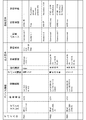
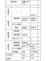
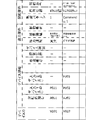
- FIGS. 3 to 5 are diagrams showing configuration examples of the physical device master DB 24, the algorithm master DB 26, and the virtual device master DB 25, respectively.
- the physical device master DB 24 is a database in which information related to physical devices (real sensors and real actuators) that physically exist is registered, and is also referred to as a real device DB.
- information of all devices 10 constituting the device network 1 is registered.
- Device registration in the physical device master DB 24 is performed by the owner of the device 10 or the operator of this system.
- FIG. 3 registered contents of “monitoring camera” which is an example of a sensor and “electronic bulletin board” and “speaker” which are examples of an actuator are illustrated.
- Device ID is information for identifying a device, and a different ID is assigned to each device.
- “Device information” is a part in which basic information of a device is described, and “device address” (network address when communicating with the device, such as an IP address), “owner ID” (device owner) ), “Installation location” (information specifying the location where the device is installed. For example, latitude and longitude information), “device type” (information indicating the type or application of the sensor or actuator. For example, monitoring Information such as camera, temperature sensor, electric bulletin board ).
- “Output requirement” is information for specifying the output of the device.
- information relating to sensing data output from the sensor includes “output type” (information indicating the data type of sensing data. For example, video, image, weather, temperature,...), “Target area” (sensing data).
- Information specifying the target area for example, latitude / longitude for a single point, central latitude / longitude + radius for an area), and “constraint conditions” (for example, time zone and period for which output can be obtained) Including.
- information relating to output from the actuator includes “output type” (information indicating the output form of the actuator.
- Target area identifying the area where the action acts. For example, latitude and longitude for one point, latitude and longitude of the center for an area), “constraint conditions” (for example, available time zone and period), etc. Contains information.
- “Contract requirement” is information indicating a use condition when using the device, and “use amount” and “contract condition” are set for each of one or more “use patterns” for each device.
- the following three types of usage patterns are prepared for the monitoring camera with the device ID “P001”.
- ⁇ Commercial 1 Usage fee is ⁇ 100 per month. No contract terms.
- ⁇ Academic 1 Usage fee is free. However, the resolution is limited to QVGA and limited to academic use.
- the algorithm master DB 26 is a database in which information on processing modules used in the virtual device is registered, and is also called a processing module DB.
- a processing module is an algorithm or rule that takes an output from one or more devices as an input and generates a new output by combining these inputs. Creation / registration of a processing module is performed by the creator of the processing module or the operator of this system.
- FIG. 4 illustrates a processing module that predicts the weather based on weather map data obtained from one sensor, and a processing module that realizes video broadcast by combining two actuator outputs of image output and audio output. ing.
- Processing ID is information for identifying a processing module, and a different ID is assigned to each processing module.
- Cosmetic ID is information for identifying the creator of the processing module. When a processing module is used, a price corresponding to a contract condition described later is paid to the creator of the processing module.
- Output requirement is information for specifying the output of the processing module. Basically, information in the same format as the “output requirement” in the physical device master DB 24 is registered. However, for the “target region”, not only a fixed value such as latitude and longitude, but also a relative position based on the position described by the variable (X1) such as “region having a radius of 10 km centered on the coordinate X1”. The target area can also be defined with. If the position of the device combined with the processing module in the real space is determined, the value of this variable is determined based on the target area of the device.
- Constract requirement is information indicating a use condition when using the processing module, and “use amount” and “contract condition” are set for each or one “use pattern” for each process module.
- Input requirement is information for specifying the input of the processing module.
- One or more input requirements are defined for one processing module.
- Input requirements include “type” (data type of sensing data in the case of sensors, output form of actuator in the case of actuators), “device type” (information indicating the type and application of the sensor or actuator), and “constraint conditions”.
- Information on the sensing target area, time zone, period, etc. in the case of a sensor, and in the case of an actuator, information on the range, time zone, period, etc. on which the output of the actuator acts is included.
- Processing content is information such as a processing program for analyzing and processing sensing data obtained from the sensor and a processing program for controlling the actuator. For example, a URI indicating the storage destination of the processing program is registered.
- the virtual device master DB 25 is a database in which information related to virtual devices (virtual sensors and virtual actuators) is registered, and is also referred to as a virtual device DB. Information about a plurality of virtual devices can be registered in the virtual device master DB 25.
- the creation / registration of a virtual device may be performed by the creator of the virtual device or the operator of this system, or may be performed dynamically in the device search process as will be described later.
- FIG. 5 registered contents of an example of a virtual sensor (ID: V001) that senses the weather of 10 km around Kusatsu and an example of a virtual actuator (ID: V002) that performs video broadcasting in an area with a radius of 10 m in front of the station today are illustrated. Yes.
- Device ID is information for identifying a device, and a different ID is assigned to each device. Of course, device IDs do not overlap between a virtual device and a real device.
- “Device information” is a part in which basic information of a virtual device is described. “Process ID”, “Device ID of input 1”, “Device ID of input 2”,..., “Creator ID”, “Installation” Information such as “location” and “device type” is included.
- the process ID is an ID of a process module used in the virtual device.
- the device ID of input n is the ID of another device used as input. One or more input devices are registered.
- the creator ID is an ID indicating the creator of the virtual device
- the installation location is information indicating the virtual installation location of the virtual device
- the device type is information indicating the virtual device type of the virtual device.
- the creator ID, installation location, and device type may be undefined (for example, when a virtual device is dynamically generated by the system, the creator ID is undefined).
- Output requirement is information for specifying the output of the virtual device
- contract requirement is information relating to the virtual device usage contract.
- the “output requirement” and “contract requirement” are information having the same significance as the information of the same name of the physical device, and thus description thereof is omitted.
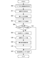
- FIG. 6 is a flowchart showing the overall flow of the device search process
- FIG. 7 is a flowchart showing details of the component search process called in the device search process.
- FIG. 8 is a diagram for explaining a procedure for dynamically generating a virtual device.
- the search request receiving unit 20 acquires a search request from the user terminal 3 (step S60), and extracts and searches information (output requirement) for specifying an output result desired by the user from the search request.
- a query is generated (step S61). For example, when a search request “I want to know the weather in Kusatsu city” is given as shown in FIG. 2A, the search request receiving unit 20 performs morphological analysis and semantic analysis to search from this text. Information “weather” indicating the data type and information “Kusatsu City” indicating the target area are extracted, and a search query including an output requirement “data type: weather, target area: Kusatsu City” is generated.
- the DB search unit 21 searches the physical device master DB 24 based on the search query (step S62). Specifically, the DB search unit 21 compares the content of the output requirement included in the search query with the content of the output requirement included in the record of each device in the physical device master DB 24, and the desired specified in the search request.
- the real device that can obtain the output result of is extracted. For example, if the output requirement of the search query is “data type: weather, target area: Kusatsu city”, the output type matches or is similar to “weather” and the target area matches “Kusatsu city”. Alternatively, when “Kusatsu City” is included, the device is extracted.
- the DB search unit 21 performs a similar search for the virtual device master DB 25 (step S63). Also in this case, the corresponding virtual device is extracted by comparing the content of the output requirement included in the search query with the content of the output requirement included in the record of each virtual device of the virtual device master DB 25. If the number of devices extracted by the search processing in steps S62 and S63 is equal to or greater than the threshold, the process proceeds to search result provision processing. If the number of extracted devices is less than the threshold, The process proceeds to the virtual device dynamic generation process (step S64).
- the threshold can be set arbitrarily.
- the threshold is set to 1, the dynamic generation process of the virtual device is skipped when at least one real device or virtual device that satisfies the user search request is found by the DB search. Conversely, if the threshold is set to a very large value, it is possible to control so that the dynamic generation process of the virtual device is always performed. Note that the search processing in steps S62 and S63 may be executed in parallel.
- the device combination reasoning unit 22 first performs processing module extraction processing (step S65).
- processing module extraction process a process capable of obtaining an output result desired by the user by comparing the content of the output requirement included in the search query with the content of the output requirement included in the record of each processing module of the algorithm master DB 26. Extract the module. For example, if the output requirement of the search query is “data type: weather, target area: Kusatsu city”, the output type is the same as or similar to “weather”, and the range is determined by the target area and the constraint condition. When “Kusatsu City” can be included, the processing module is extracted.
- the target area is defined as a variable “radius 10 km from the center of X1” as in the processing module (A001) of FIG. 4, the coordinates of the central point of Kusatsu City are applied to the variable X1. You can judge whether the requirement is satisfied.
- the device combination inference unit 22 executes a component element search process for the extracted processing module (step S66).
- the configuration requirement search process is to extract a device having an output that can be used as an input of the processing module by comparing each input requirement of the processing module and the output requirement of each device. Is a process for generating a new virtual device.
- the argument of the configuration requirement search process is a search query and the ID of a processing module, and the return value is a list of generated virtual devices.
- a loop L00 indicates that the same processing is repeated for each processing module when one or more processing modules are extracted.
- Fig. 7 shows the detailed flow of the component search process.
- a loop L01 indicates that the same processing is repeated for each input requirement included in the processing module.
- the device combination reasoning unit 22 generates a new search query from the contents of the “type”, “constraint condition”, and the content of the original search query. (Step S70). For example, in the case of the processing module (A001) of FIG. 4, since the “type” of the input requirement is “weather map” and the “restriction condition” is “radius 500 km at the center of X1,” “data type: weather map, target area” : A search query with a content of “500 km radius from the center of Kusatsu City” is generated.
- the device combination reasoning unit 22 searches the physical device master DB 24, the virtual device master DB 25, and the algorithm master DB 26 using the search query generated in step S70 (step S71).
- the search process here is the same as that described in steps S62, S63, and S65.
- real devices, virtual devices, and processing modules that satisfy the search query “data type: weather map, target area: radius 500 km from the center of Kusatsu City” are extracted (the extracted devices and modules are used as items). Call).
- step S71 the device combination reasoning unit 22 determines whether the target item is a real device, a virtual device, or a processing module (step S72), and if it is a processing module, recursively executes a configuration requirement search process. (Step S74). In order to prevent the recursive process from continuing indefinitely, in step S73, a determination is made to stop the recursive process when the number of searches or the search time exceeds the upper limit. By repeating steps S72 to S74 for all items (loop L02), a list of devices (real devices or virtual devices) that can meet the first input requirement of the processing module is obtained.
- the above process is repeated for all the input requirements of the processing module (loop L01), thereby obtaining a list of devices for each input requirement of the processing module.
- the device combination reasoning unit 22 generates a virtual device from the processing module and the list of devices for each input requirement (step S75).
- virtual devices may be generated for all combinations of devices, or by selecting a representative device for each input requirement (for example, real device> existing virtual device> newly generated in step 74). Only one virtual device may be generated.
- FIG. 8 schematically shows a procedure for dynamically generating a virtual device based on a user search request.
- a processing module capable of obtaining an output result desired by the user is extracted by comparing the output requirement included in the search request with the output requirement of the processing module (S80).
- a device having an output corresponding to each input requirement is extracted by comparing each input requirement of the processing module with the output requirement of each device (S81, S82).
- a new virtual device record is generated from the processing ID, output requirement, and contract requirement of the extracted processing module (S83, S84) and the device ID of each extracted device (S85, S86). Can do.
- the process exits the loop L00. Thereafter, the device information providing unit 23 creates a device list in which the real device extracted in step S62, the virtual device extracted in step S63, and the new virtual device generated in step S66 are collected. Then, a device list is transmitted from the device information providing unit 23 to the user terminal 2 and presented to the user as a search result (step S67). This completes the device search process.
- a processing module that can acquire a user-desired output result and a device that has an output that can be used as an input of the processing module are automatically generated based on a user search request.
- the virtual device is selected and automatically created. Therefore, even if there is no device that matches the user's request (not registered in the search database in advance), it is possible to meet the user's request by creating a new virtual device. Effective use of network resources and increase of usage opportunities by users can be achieved.
- the devices are searched from the three categories of existing real devices registered in the physical device master DB, existing virtual devices registered in the virtual device master DB, and newly generated virtual devices, the user's The possibility of providing device information that meets the requirements can be further expanded.
- the search for the real device and the search for the existing virtual device are preferentially executed (steps S62 and S63), and the virtual device generation process (steps S65 to S66) is performed only when the result is not sufficient. It was decided to do. As a result, it is possible to reduce the frequency of occurrence of virtual device generation processing that requires more processing load than DB search, and to reduce the processing load of the system.
- the degree of freedom in creating the virtual device can be greatly improved, and thereby the virtual device that meets the user's request The possibility that can be generated can be further expanded.
- the device combination inference unit 22 may automatically register information on the newly generated virtual device in the virtual device master DB 25. If the virtual device information once generated is registered in the virtual device master DB 25 in this way, when a similar search request is received from another user, the virtual device generation processing (steps S65 to S66) is not performed. Since it is possible to deal with only by searching the virtual device DB (step S63), it is possible to reduce the processing load of the system.
- Device network 2 Device management system 3: User terminal 10: Device 20: Search request receiving unit 21: DB search unit 22: Device combination reasoning unit 23: Device information providing unit 24: Physical device master DB 25: Virtual device master DB 26: Algorithm master DB
Landscapes
- Engineering & Computer Science (AREA)
- Theoretical Computer Science (AREA)
- Databases & Information Systems (AREA)
- Physics & Mathematics (AREA)
- General Engineering & Computer Science (AREA)
- General Physics & Mathematics (AREA)
- Data Mining & Analysis (AREA)
- Computational Linguistics (AREA)
- Software Systems (AREA)
- Computer Networks & Wireless Communication (AREA)
- Signal Processing (AREA)
- Health & Medical Sciences (AREA)
- Computing Systems (AREA)
- General Health & Medical Sciences (AREA)
- Medical Informatics (AREA)
- Information Retrieval, Db Structures And Fs Structures Therefor (AREA)
- Mobile Radio Communication Systems (AREA)
Abstract
Description
図1を参照して、本発明の実施形態に係るデバイスネットワークシステムの構成例を説明する。
以下、デバイス管理システム2が提供するデバイス情報提供サービスについて、詳しく説明する。デバイス情報提供サービスとは、デバイスネットワーク1を構成する多数のデバイス10の中から、ユーザが目的達成に最適なデバイスを見つけることを容易化するための検索サービスである。センサを検索するためのセンサ情報提供サービスと、アクチュエータを検索するためのアクチュエータ情報提供サービスとがある。まずは図2(a)~(c)を用いてセンサ情報提供サービスの具体的な使用例から説明する。
本システムのデバイス情報提供サービスは、検索結果として、物理的に存在する実デバイス(実センサ、実アクチュエータ)の情報だけでなく、仮想デバイス(仮想センサ、仮想アクチュエータ)の情報も提供するところに特徴を有している。仮想デバイスとは、1又は複数個のデバイスと処理モジュールとの組み合わせで構成される、仮想的なデバイスのことである。
次に、デバイス情報提供サービスに利用されるデータベースの構造について説明する。図3~図5は、それぞれ、物理デバイスマスターDB24、アルゴリズムマスターDB26、仮想デバイスマスターDB25の構成例を示す図である。
物理デバイスマスターDB24は、物理的に存在する実デバイス(実センサ及び実アクチュエータ)に関する情報を登録したデータベースであり、実デバイスDBとも呼ばれる。物理デバイスマスターDB24には、デバイスネットワーク1を構成している全てのデバイス10の情報が登録されている。物理デバイスマスターDB24へのデバイス登録は、デバイス10の所有者又は本システムの運営者により行われる。図3では、センサの一例である「監視カメラ」と、アクチュエータの一例である「電光掲示板」及び「スピーカ」の登録内容が例示されている。
・Commercial 1:利用料は月額100円。契約条件はなし。
・Academic 1:利用料はフリー。ただし、解像度がQVGAまでに制限され、学術的利用に限られる。
・Academic 2:利用料は月額50円。ただし、解像度がVGAまでに制限される。
アルゴリズムマスターDB26は、仮想デバイスで利用される処理モジュールに関する情報を登録したデータベースであり、処理モジュールDBとも呼ばれる。処理モジュールとは、1又は複数個のデバイスからの出力を入力とし、それらの入力を組み合わせて新たな出力を生成するアルゴリズム又はルールのことである。処理モジュールの作成・登録は、処理モジュールの作成者又は本システムの運営者により行われる。図4には、1つのセンサから得られる天気図のデータを元に天気を予測する処理モジュールと、画像出力と音声出力の2つのアクチュエータ出力を組み合わせてビデオ放映を実現する処理モジュールとが例示されている。
仮想デバイスマスターDB25は、仮想デバイス(仮想センサ及び仮想アクチュエータ)に関する情報を登録したデータベースであり、仮想デバイスDBとも呼ばれる。仮想デバイスマスターDB25には、複数の仮想デバイスの情報を登録することが可能である。仮想デバイスの作成・登録は、仮想デバイスの作成者又は本システムの運営者により行われる場合もあるし、後述するように、デバイス検索処理の中で動的に行われる場合もある。図5では、草津周辺10kmの天気をセンシングする仮想センサの一例(ID:V001)と、今日駅前半径10mのエリアにビデオ放映を行う仮想アクチュエータの一例(ID:V002)の登録内容が例示されている。
続いて、図6~図8を参照して、デバイス管理システム2によるデバイス検索処理を説明する。図6はデバイス検索処理の全体フローを示すフローチャートであり、図7はデバイス検索処理の中で呼び出される構成要素検索処理の詳細を示すフローチャートである。また、図8は仮想デバイスを動的に生成する手順を説明する図である。
以上述べた本実施形態の構成によれば、ユーザの検索要求に基づいて、ユーザ所望の出力結果を取得可能な処理モジュールと、その処理モジュールの入力として利用可能な出力をもつデバイスとが自動で選定され、仮想デバイスが自動で生成される。したがって、ユーザの要求に合致するデバイスが存在しない(予め検索用のデータベースに登録されていない)場合であっても、新たな仮想デバイスを創りだすことでユーザの要求に応じることができるため、デバイスネットワークのリソースの有効利用、ユーザによる利用機会の増大などを図ることができる。また、ユーザにとっては、既存のデバイスと仮想デバイスとを区別なく検索可能となり、利便性が向上する。さらに、物理デバイスマスターDBに登録された既存の実デバイス、仮想デバイスマスターDBに登録された既存の仮想デバイス、新たに生成される仮想デバイスの3つのカテゴリから、デバイスが検索されるので、ユーザの要求に合致したデバイスの情報を提供できる可能性を一層拡大することができる。
2:デバイス管理システム
3:ユーザ端末
10:デバイス
20:検索要求受付部
21:DB検索部
22:デバイス組合せ推論部
23:デバイス情報提供部
24:物理デバイスマスターDB
25:仮想デバイスマスターDB
26:アルゴリズムマスターDB
Claims (11)
- デバイスを検索するための検索要求として、所望の出力結果を特定するための出力要件を含む検索要求を受け付ける検索要求受付手段と、
1又は複数の他のデバイスからの出力を入力とし、それらの入力を組み合わせて新たな出力を生成する処理モジュールに関する情報を、少なくとも、処理モジュールの入力を特定するための入力要件、及び、処理モジュールの出力を特定するための出力要件と共に、複数の処理モジュールについて登録した処理モジュールDBと、
デバイスに関する情報を、少なくとも、デバイスの出力を特定するための出力要件と共に、複数のデバイスについて登録したデバイスDBと、
前記検索要求に含まれる出力要件と、各処理モジュールの出力要件とを比較することによって、前記検索要求で指定された前記所望の出力結果を取得可能な処理モジュールを前記処理モジュールDBから抽出する処理モジュール抽出手段と、
前記抽出された処理モジュールの入力要件と、各デバイスの出力要件とを比較することによって、前記抽出された処理モジュールの入力として利用可能な出力をもつ1又は複数のデバイスを前記デバイスDBから抽出して、前記抽出した1又は複数のデバイスと前記抽出した処理モジュールの組み合わせからなる仮想デバイスを生成する仮想デバイス生成手段と、
前記仮想デバイス生成手段で生成された仮想デバイスの情報を検索結果としてユーザに提供するデバイス情報提供手段と、を有する
ことを特徴とするデバイス情報提供システム。 - 前記検索要求に含まれる出力要件と、各デバイスの出力要件とを比較することによって、前記検索要求で指定された前記所望の出力結果を取得可能なデバイスを前記デバイスDBから抽出するデバイス抽出手段をさらに有し、
前記デバイス情報提供手段は、前記デバイス抽出手段で抽出されたデバイスの情報を検索結果としてユーザに提供する
ことを特徴とする請求項1に記載のデバイス情報提供システム。 - 前記デバイス抽出手段によるデバイスの抽出処理は、前記処理モジュール抽出手段による処理モジュールの抽出処理及び前記仮想デバイス生成手段による仮想デバイスの生成処理よりも優先的に行われる
ことを特徴とする請求項2に記載のデバイス情報提供システム。 - 前記デバイス抽出手段によるデバイスの抽出結果が所定の条件に達しない場合にのみ、前記処理モジュール抽出手段による処理モジュールの抽出処理及び前記仮想デバイス生成手段による仮想デバイスの生成処理が行われる
ことを特徴とする請求項3に記載のデバイス情報提供システム。 - 前記デバイスDBは、物理的に存在する実デバイスに関する情報を登録した実デバイスDBと、仮想デバイスに関する情報を登録した仮想デバイスDBとを有する
ことを特徴とする請求項1~4のうちいずれか1項に記載のデバイス情報提供システム。 - 前記仮想デバイス生成手段は、前記抽出された処理モジュールの入力として利用可能な出力をもつデバイスを、前記実デバイスDBに登録されている実デバイスと前記仮想デバイスDBに登録されている仮想デバイスのなかから抽出する
ことを特徴とする請求項5に記載のデバイス情報提供システム。 - 前記仮想デバイス生成手段によって新たに仮想デバイスが生成された場合に、当該新たな仮想デバイスに関する情報が前記仮想デバイスDBに自動で登録される
ことを特徴とする請求項5又は6に記載のデバイス情報提供システム。 - センサを検索するための検索要求として、所望のセンシングデータを特定するためのデータ要件を含む検索要求を受け付ける検索要求受付手段と、
1又は複数のセンシングデータを加工して新たなセンシングデータを生成する処理モジュールに関する情報を、少なくとも、入力として用いるセンシングデータのデータ要件である入力要件、及び、生成する新たなセンシングデータのデータ要件である出力要件と共に、複数の処理モジュールについて登録した処理モジュールDBと、
センサに関する情報を、少なくとも、出力するセンシングデータのデータ要件である出力要件と共に、複数のセンサについて登録したセンサDBと、
前記検索要求に含まれるデータ要件と、各処理モジュールの出力要件とを比較することによって、前記検索要求で指定された前記所望のセンシングデータを生成可能な処理モジュールを前記処理モジュールDBから抽出する処理モジュール抽出手段と、
前記抽出された処理モジュールの入力要件と、各センサの出力要件とを比較することによって、前記抽出された処理モジュールの入力として用いるセンシングデータを取得可能な1又は複数のセンサを前記センサDBから抽出して、前記抽出した1又は複数のセンサと前記抽出した処理モジュールの組み合わせからなる仮想センサを生成する仮想センサ生成手段と、
前記仮想センサ生成手段で生成された仮想センサの情報を検索結果としてユーザに提供するセンサ情報提供手段と、を有する
ことを特徴とするデバイス情報提供システム。 - 1又は複数の他のデバイスからの出力を入力とし、それらの入力を組み合わせて新たな出力を生成する処理モジュールに関する情報を、少なくとも、処理モジュールの入力を特定するための入力要件、及び、処理モジュールの出力を特定するための出力要件と共に、複数の処理モジュールについて登録した処理モジュールDBと、
デバイスに関する情報を、少なくとも、デバイスの出力を特定するための出力要件と共に、複数のデバイスについて登録したデバイスDBと、を有するコンピュータが、
デバイスを検索するための検索要求として、所望の出力結果を特定するための出力要件を含む検索要求を受け付けるステップと、
前記検索要求に含まれる出力要件と、各処理モジュールの出力要件とを比較することによって、前記検索要求で指定された前記所望の出力結果を取得可能な処理モジュールを前記処理モジュールDBから抽出するステップと、
前記抽出された処理モジュールの入力要件と、各デバイスの出力要件とを比較することによって、前記抽出された処理モジュールの入力として利用可能な出力をもつ1又は複数のデバイスを前記デバイスDBから抽出して、前記抽出した1又は複数のデバイスと前記抽出した処理モジュールの組み合わせからなる仮想デバイスを生成するステップと、
前記生成された仮想デバイスの情報を検索結果としてユーザに提供するステップと、を実行する
ことを特徴とするデバイス情報提供方法。 - 1又は複数のセンシングデータを分析加工して新たなセンシングデータを生成する処理モジュールに関する情報を、少なくとも、入力として用いるセンシングデータのデータ要件である入力要件、及び、生成する新たなセンシングデータのデータ要件である出力要件と共に、複数の処理モジュールについて登録した処理モジュールDBと、
センサに関する情報を、少なくとも、出力するセンシングデータのデータ要件である出力要件と共に、複数のセンサについて登録したセンサDBと、を有するコンピュータが、
センサを検索するための検索要求として、所望のセンシングデータを特定するためのデータ要件を含む検索要求を受け付けるステップと、
前記検索要求に含まれるデータ要件と、各処理モジュールの出力要件とを比較することによって、前記検索要求で指定された前記所望のセンシングデータを生成可能な処理モジュールを前記処理モジュールDBから抽出するステップと、
前記抽出された処理モジュールの入力要件と、各センサの出力要件とを比較することによって、前記抽出された処理モジュールの入力として用いるセンシングデータを取得可能な1又は複数のセンサを前記センサDBから抽出して、前記抽出した1又は複数のセンサと前記抽出した処理モジュールの組み合わせからなる仮想センサを生成するステップと、
前記生成された仮想センサの情報を検索結果としてユーザに提供するステップと、を実行する
ことを特徴とするデバイス情報提供方法。 - 請求項9又は10に記載のデバイス情報提供方法の各ステップをコンピュータに実行させる
ことを特徴とするプログラム。
Priority Applications (4)
| Application Number | Priority Date | Filing Date | Title |
|---|---|---|---|
| US14/437,920 US9679032B2 (en) | 2014-02-26 | 2014-02-26 | Device information providing system and device information providing method |
| JP2015518669A JP5822050B1 (ja) | 2014-02-26 | 2014-02-26 | デバイス情報提供システム、デバイス情報提供方法 |
| EP14854884.5A EP2940601B1 (en) | 2014-02-26 | 2014-02-26 | Device information providing system and device information providing method |
| PCT/JP2014/054632 WO2015128954A1 (ja) | 2014-02-26 | 2014-02-26 | デバイス情報提供システム、デバイス情報提供方法 |
Applications Claiming Priority (1)
| Application Number | Priority Date | Filing Date | Title |
|---|---|---|---|
| PCT/JP2014/054632 WO2015128954A1 (ja) | 2014-02-26 | 2014-02-26 | デバイス情報提供システム、デバイス情報提供方法 |
Publications (1)
| Publication Number | Publication Date |
|---|---|
| WO2015128954A1 true WO2015128954A1 (ja) | 2015-09-03 |
Family
ID=54008326
Family Applications (1)
| Application Number | Title | Priority Date | Filing Date |
|---|---|---|---|
| PCT/JP2014/054632 Ceased WO2015128954A1 (ja) | 2014-02-26 | 2014-02-26 | デバイス情報提供システム、デバイス情報提供方法 |
Country Status (4)
| Country | Link |
|---|---|
| US (1) | US9679032B2 (ja) |
| EP (1) | EP2940601B1 (ja) |
| JP (1) | JP5822050B1 (ja) |
| WO (1) | WO2015128954A1 (ja) |
Cited By (2)
| Publication number | Priority date | Publication date | Assignee | Title |
|---|---|---|---|---|
| WO2022163415A1 (ja) * | 2021-01-28 | 2022-08-04 | パナソニックホールディングス株式会社 | 可搬型仮想IoT装置、それを用いた仮想デバイスデータの生成方法、及びそのプログラム |
| US11422914B2 (en) | 2018-02-27 | 2022-08-23 | Omron Corporation | Metadata generation apparatus, metadata generation method, and program |
Families Citing this family (6)
| Publication number | Priority date | Publication date | Assignee | Title |
|---|---|---|---|---|
| JP6465012B2 (ja) * | 2015-12-14 | 2019-02-06 | オムロン株式会社 | データフロー制御装置およびデータフロー制御方法 |
| JP6406341B2 (ja) * | 2016-12-15 | 2018-10-17 | オムロン株式会社 | センシングデータ流通システムとその装置およびプログラム |
| US10866950B2 (en) | 2017-12-06 | 2020-12-15 | Motorola Solutions, Inc. | Method and system for modifying a search request corresponding to a person, object, or entity (POE) of interest |
| US11301273B2 (en) | 2020-03-11 | 2022-04-12 | Atlassian Pty Ltd. | Computer user interface for a virtual workspace having multiple application portals displaying context-related content |
| WO2022157873A1 (ja) * | 2021-01-21 | 2022-07-28 | 三菱電機株式会社 | 情報処理装置、情報処理方法及び情報処理プログラム |
| EP4321947A1 (en) * | 2022-08-09 | 2024-02-14 | Abb Schweiz Ag | Communicating with field devices based on semantically identified variables |
Citations (4)
| Publication number | Priority date | Publication date | Assignee | Title |
|---|---|---|---|---|
| JP2005260914A (ja) | 2003-12-11 | 2005-09-22 | Sony Internatl Europ Gmbh | 動的な情報ソース管理 |
| JP2011118950A (ja) * | 2011-03-18 | 2011-06-16 | Hitachi Ltd | センサネットワークシステム、センサデータの検索方法 |
| WO2013024673A1 (ja) * | 2011-08-12 | 2013-02-21 | オムロン株式会社 | 情報管理装置、ネットワークシステム、情報管理プログラム、および情報管理方法 |
| WO2013153890A1 (ja) * | 2012-04-12 | 2013-10-17 | オムロン株式会社 | デバイス管理装置及びデバイス検索方法 |
Family Cites Families (13)
| Publication number | Priority date | Publication date | Assignee | Title |
|---|---|---|---|---|
| US20060284839A1 (en) * | 1999-12-15 | 2006-12-21 | Automotive Technologies International, Inc. | Vehicular Steering Wheel with Input Device |
| JP4885463B2 (ja) * | 2005-03-03 | 2012-02-29 | 株式会社日立製作所 | センサネットワークシステム、センサデータの処理方法及びプログラム |
| US8655939B2 (en) * | 2007-01-05 | 2014-02-18 | Digital Doors, Inc. | Electromagnetic pulse (EMP) hardened information infrastructure with extractor, cloud dispersal, secure storage, content analysis and classification and method therefor |
| US8385971B2 (en) * | 2008-08-19 | 2013-02-26 | Digimarc Corporation | Methods and systems for content processing |
| US9183560B2 (en) * | 2010-05-28 | 2015-11-10 | Daniel H. Abelow | Reality alternate |
| US9225793B2 (en) * | 2011-01-28 | 2015-12-29 | Cisco Technology, Inc. | Aggregating sensor data |
| US9275093B2 (en) * | 2011-01-28 | 2016-03-01 | Cisco Technology, Inc. | Indexing sensor data |
| US20120197856A1 (en) * | 2011-01-28 | 2012-08-02 | Cisco Technology, Inc. | Hierarchical Network for Collecting, Aggregating, Indexing, and Searching Sensor Data |
| US9171079B2 (en) * | 2011-01-28 | 2015-10-27 | Cisco Technology, Inc. | Searching sensor data |
| US9417754B2 (en) * | 2011-08-05 | 2016-08-16 | P4tents1, LLC | User interface system, method, and computer program product |
| WO2013032955A1 (en) * | 2011-08-26 | 2013-03-07 | Reincloud Corporation | Equipment, systems and methods for navigating through multiple reality models |
| US20140063061A1 (en) * | 2011-08-26 | 2014-03-06 | Reincloud Corporation | Determining a position of an item in a virtual augmented space |
| US20150256355A1 (en) * | 2014-03-07 | 2015-09-10 | Robert J. Pera | Wall-mounted interactive sensing and audio-visual node devices for networked living and work spaces |
-
2014
- 2014-02-26 EP EP14854884.5A patent/EP2940601B1/en active Active
- 2014-02-26 WO PCT/JP2014/054632 patent/WO2015128954A1/ja not_active Ceased
- 2014-02-26 US US14/437,920 patent/US9679032B2/en active Active
- 2014-02-26 JP JP2015518669A patent/JP5822050B1/ja active Active
Patent Citations (4)
| Publication number | Priority date | Publication date | Assignee | Title |
|---|---|---|---|---|
| JP2005260914A (ja) | 2003-12-11 | 2005-09-22 | Sony Internatl Europ Gmbh | 動的な情報ソース管理 |
| JP2011118950A (ja) * | 2011-03-18 | 2011-06-16 | Hitachi Ltd | センサネットワークシステム、センサデータの検索方法 |
| WO2013024673A1 (ja) * | 2011-08-12 | 2013-02-21 | オムロン株式会社 | 情報管理装置、ネットワークシステム、情報管理プログラム、および情報管理方法 |
| WO2013153890A1 (ja) * | 2012-04-12 | 2013-10-17 | オムロン株式会社 | デバイス管理装置及びデバイス検索方法 |
Non-Patent Citations (1)
| Title |
|---|
| See also references of EP2940601A4 |
Cited By (2)
| Publication number | Priority date | Publication date | Assignee | Title |
|---|---|---|---|---|
| US11422914B2 (en) | 2018-02-27 | 2022-08-23 | Omron Corporation | Metadata generation apparatus, metadata generation method, and program |
| WO2022163415A1 (ja) * | 2021-01-28 | 2022-08-04 | パナソニックホールディングス株式会社 | 可搬型仮想IoT装置、それを用いた仮想デバイスデータの生成方法、及びそのプログラム |
Also Published As
| Publication number | Publication date |
|---|---|
| JPWO2015128954A1 (ja) | 2017-03-30 |
| US20160299902A1 (en) | 2016-10-13 |
| EP2940601A1 (en) | 2015-11-04 |
| EP2940601A4 (en) | 2016-10-12 |
| US9679032B2 (en) | 2017-06-13 |
| EP2940601B1 (en) | 2018-01-03 |
| JP5822050B1 (ja) | 2015-11-24 |
Similar Documents
| Publication | Publication Date | Title |
|---|---|---|
| JP5822050B1 (ja) | デバイス情報提供システム、デバイス情報提供方法 | |
| JP6791569B2 (ja) | ユーザプロファイル生成方法および端末 | |
| JP6365519B2 (ja) | データフロー制御装置およびデータフロー制御方法 | |
| US9542440B2 (en) | Enterprise graph search based on object and actor relationships | |
| US11288511B2 (en) | System and method for displaying pertinent data to supplement information in images provided from a mobile communication device using augmented reality | |
| US10896347B2 (en) | Dataflow control apparatus and dataflow control method for metadata matching and device extraction | |
| KR102325310B1 (ko) | 데이터 중개 시스템 및 방법 | |
| EP2902913A1 (en) | Device management apparatus and device search method | |
| US11184307B2 (en) | System, apparatus, method, and non-transitory computer readable medium for providing location information by transmitting an image including the location information through a chatroom | |
| WO2015084678A1 (en) | Systems and methods for geo-location based message streams | |
| JP2012014652A (ja) | コンテンツ配信システム及びコンテンツ配信方法 | |
| US20150331930A1 (en) | Method and apparatus for classification of media based on metadata | |
| CN110798444A (zh) | 一种基于物联网的数据同步方法以及装置 | |
| KR101612362B1 (ko) | 자동 크라우드소스 데이터 수집을 위한 자동 코드 생성 | |
| US10599380B2 (en) | Method and system for automatically managing content in an electronic device | |
| US10003620B2 (en) | Collaborative analytics with edge devices | |
| JP2014153797A (ja) | デバイス情報提供システム、デバイス情報提供方法 | |
| US20130151553A1 (en) | Method and apparatus for processing a composite context event | |
| Aamir et al. | Social-sensor composition for scene analysis | |
| US10455365B1 (en) | System and method for optimized tracking and identification of user equipment | |
| Hussain et al. | Searching for IoT Resources in Intelligent Transportation Cyberspace (T-CPS)—Requirements, Use-Cases and Security Aspects | |
| KR20140073073A (ko) | 전화번호 조회 방법 및 시스템 | |
| US20150310108A1 (en) | Apparatus and method for collecting media | |
| CN104301361B (zh) | 一种基于m2m系统的智能导览方法和系统 | |
| WO2023105568A1 (ja) | 情報提供装置、情報提供方法及びプログラム |
Legal Events
| Date | Code | Title | Description |
|---|---|---|---|
| ENP | Entry into the national phase |
Ref document number: 2015518669 Country of ref document: JP Kind code of ref document: A |
|
| WWE | Wipo information: entry into national phase |
Ref document number: 14437920 Country of ref document: US |
|
| WWE | Wipo information: entry into national phase |
Ref document number: 2014854884 Country of ref document: EP |
|
| 121 | Ep: the epo has been informed by wipo that ep was designated in this application |
Ref document number: 14854884 Country of ref document: EP Kind code of ref document: A1 |
|
| NENP | Non-entry into the national phase |
Ref country code: DE |