WO2015129147A1 - 電力制御装置およびパワーコンディショナ - Google Patents
電力制御装置およびパワーコンディショナ Download PDFInfo
- Publication number
- WO2015129147A1 WO2015129147A1 PCT/JP2015/000116 JP2015000116W WO2015129147A1 WO 2015129147 A1 WO2015129147 A1 WO 2015129147A1 JP 2015000116 W JP2015000116 W JP 2015000116W WO 2015129147 A1 WO2015129147 A1 WO 2015129147A1
- Authority
- WO
- WIPO (PCT)
- Prior art keywords
- power
- peak
- value
- operating point
- unit
- Prior art date
- Legal status (The legal status is an assumption and is not a legal conclusion. Google has not performed a legal analysis and makes no representation as to the accuracy of the status listed.)
- Ceased
Links
Images


Classifications
-
- G—PHYSICS
- G05—CONTROLLING; REGULATING
- G05F—SYSTEMS FOR REGULATING ELECTRIC OR MAGNETIC VARIABLES
- G05F1/00—Automatic systems in which deviations of an electric quantity from one or more predetermined values are detected at the output of the system and fed back to a device within the system to restore the detected quantity to its predetermined value or values, i.e. retroactive systems
- G05F1/66—Regulating electric power
- G05F1/67—Regulating electric power to the maximum power available from a generator, e.g. from solar cell
-
- H—ELECTRICITY
- H02—GENERATION; CONVERSION OR DISTRIBUTION OF ELECTRIC POWER
- H02M—APPARATUS FOR CONVERSION BETWEEN AC AND AC, BETWEEN AC AND DC, OR BETWEEN DC AND DC, AND FOR USE WITH MAINS OR SIMILAR POWER SUPPLY SYSTEMS; CONVERSION OF DC OR AC INPUT POWER INTO SURGE OUTPUT POWER; CONTROL OR REGULATION THEREOF
- H02M3/00—Conversion of DC power input into DC power output
- H02M3/02—Conversion of DC power input into DC power output without intermediate conversion into AC
- H02M3/04—Conversion of DC power input into DC power output without intermediate conversion into AC by static converters
- H02M3/08—Conversion of DC power input into DC power output without intermediate conversion into AC by static converters using discharge tubes without control electrode or semiconductor devices without control electrode
-
- H—ELECTRICITY
- H02—GENERATION; CONVERSION OR DISTRIBUTION OF ELECTRIC POWER
- H02M—APPARATUS FOR CONVERSION BETWEEN AC AND AC, BETWEEN AC AND DC, OR BETWEEN DC AND DC, AND FOR USE WITH MAINS OR SIMILAR POWER SUPPLY SYSTEMS; CONVERSION OF DC OR AC INPUT POWER INTO SURGE OUTPUT POWER; CONTROL OR REGULATION THEREOF
- H02M7/00—Conversion of AC power input into DC power output; Conversion of DC power input into AC power output
- H02M7/42—Conversion of DC power input into AC power output without possibility of reversal
- H02M7/44—Conversion of DC power input into AC power output without possibility of reversal by static converters
-
- H—ELECTRICITY
- H02—GENERATION; CONVERSION OR DISTRIBUTION OF ELECTRIC POWER
- H02S—GENERATION OF ELECTRIC POWER BY CONVERSION OF INFRARED RADIATION, VISIBLE LIGHT OR ULTRAVIOLET LIGHT, e.g. USING PHOTOVOLTAIC [PV] MODULES
- H02S40/00—Components or accessories in combination with PV modules, not provided for in groups H02S10/00 - H02S30/00
- H02S40/30—Electrical components
-
- Y—GENERAL TAGGING OF NEW TECHNOLOGICAL DEVELOPMENTS; GENERAL TAGGING OF CROSS-SECTIONAL TECHNOLOGIES SPANNING OVER SEVERAL SECTIONS OF THE IPC; TECHNICAL SUBJECTS COVERED BY FORMER USPC CROSS-REFERENCE ART COLLECTIONS [XRACs] AND DIGESTS
- Y02—TECHNOLOGIES OR APPLICATIONS FOR MITIGATION OR ADAPTATION AGAINST CLIMATE CHANGE
- Y02E—REDUCTION OF GREENHOUSE GAS [GHG] EMISSIONS, RELATED TO ENERGY GENERATION, TRANSMISSION OR DISTRIBUTION
- Y02E10/00—Energy generation through renewable energy sources
- Y02E10/50—Photovoltaic [PV] energy
- Y02E10/56—Power conversion systems, e.g. maximum power point trackers
Definitions
- the present invention relates to a power control device, and more particularly to a power control device that controls the output of a power source that varies in the amount of power generation, such as a solar cell, and a power control device that converts DC power of the power source into AC power and a power conditioner. .
- solar cells As a photoelectric conversion device that converts light energy into electrical energy, so-called solar cells have been vigorously developed in various directions. Solar cells are expected to be a new energy source because they can directly convert light from the sun, a clean and inexhaustible energy source, into electricity.
- the solar cell module is operated at an optimum operating voltage by a maximum power point tracking method (MPPT: Maximum Power Point Tracking) control process by a microcomputer, and converted into electric power corresponding to a load or a commercial power system by an inverter (for example, patent Reference 1).
- MPPT Maximum Power Point Tracking
- the solar cell module is generally controlled by the MPPT controller so that the operating point becomes the maximum output point.
- a plurality of solar cells are connected in series, and the currents flowing through the solar cells are equal.
- a reverse bias is applied by another solar cell in order to increase the current value of the solar cell. The At this time, a hot spot phenomenon occurs in which a solar cell to which a reverse bias is applied consumes electric power and enters a high temperature state.
- the present invention has been made in view of such circumstances, and the object of the present invention is to provide a technique for suppressing a temperature rise when a hot spot phenomenon occurs or when a hot spot phenomenon is expected to occur. It is to provide.
- a power control apparatus includes a detection unit that detects a peak of a power value in a current-voltage characteristic curve with respect to DC power output from a solar cell module, and a plurality of detection units (1) Among the plurality of peaks, if the current value at the first peak having the maximum voltage value is larger than the threshold value, the operating point is determined based on the first peak. (2) If the current value at the first peak is less than or equal to the threshold value, a second peak having a voltage value smaller than the first peak and a current value greater than the threshold value is included among the plurality of peaks. And a power adjusting unit that adjusts the output of DC power of the solar cell module according to the operating point set in the setting unit.
- Another aspect of the present invention is also a power control apparatus.
- this device detects a peak of a power value, and when a plurality of peaks are detected in the detection unit, (1) a plurality of peaks If the current value at the first peak having the maximum voltage value is larger than the threshold value, the operating point is set based on the first peak, and (2) the current value is less than the threshold value.
- a setting unit that sets an operating point based on a second peak having the maximum power value among a plurality of peaks, and an output of DC power of the solar cell module according to the operating point set in the setting unit
- a power adjustment unit that adjusts.
- An update unit that updates the operating point set in the setting unit may be further provided.
- the power adjustment unit may use the operating point updated in the update unit for conversion, and the detection unit and the setting unit may operate during a period in which the update unit is stopped.
- the DC power input to the power adjustment unit is a solar cell module in which cell groups are connected in series, and is generated by a solar cell module in which a bypass diode is connected in parallel to at least one cell group. May be.
- Still another aspect of the present invention is a power conditioner.
- This power conditioner includes: a detection unit that detects a peak of a power value in a current-voltage characteristic curve with respect to DC power output from a solar cell module; and a plurality of peaks detected by the detection unit. If the current value at the first peak having the maximum voltage value among the peaks is larger than the threshold value, the operating point is set based on the first peak. (2) The current value at the first peak A setting unit for setting an operating point based on a second peak having a voltage value smaller than the first peak and a current value larger than the threshold among the plurality of peaks, And a power adjustment unit that converts the DC power of the solar cell module into AC power according to the operating point set in (1).
- FIG. 4A to 4C are diagrams showing an outline of the operation of the setting unit in FIG.
- FIGS. 5A to 5B are diagrams illustrating the operation of the power control apparatus to be compared.
- 6 (a)-(b) are diagrams illustrating the operation of the power control apparatus of FIG.
- FIGS. 8A to 8C are diagrams showing another operation of the power control apparatus of FIG.
- the present embodiment relates to a power control device connected to a solar cell.
- the power control apparatus generally controls the operating point so as to be the maximum output point.
- the power control device sets an operating point that is the maximum output point when the influence of a shadow or dirt cell becomes large, the reverse bias applied to the solar battery cell becomes large, resulting in a high temperature state.
- the power control apparatus executes the following process.
- the power control device periodically measures a current-voltage characteristic curve (hereinafter referred to as “IV characteristic curve”) with respect to DC power from the solar cell, and obtains a peak of the power value.
- the peak of the power value corresponds to the maximum value.
- this corresponds to the influence of a shadow or dirt cell.
- the power control device Set the operating point based on the output point.
- the current value at the peak having the maximum voltage value is larger than the threshold value, the influence of the shadow or dirt cell is large, so the operating point is set based on the peak. Therefore, the maximum output point is not set as the operating point.
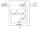
- FIG. 1 shows a configuration of a power control apparatus 100 according to an embodiment of the present invention.
- the power control apparatus 100 is connected to the solar cell module 10 and the load 12.
- the power control apparatus 100 includes a power adjustment unit 20 and a control unit 22.
- the control unit 22 includes a detection unit 24, a setting unit 26, and an update unit 28.
- the power adjusted by the power control apparatus 100 passes through a DC-DC converter (not shown). It may be supplied to the load 12.
- the solar cell module 10 is a power device that uses the photovoltaic effect to directly convert light energy into electric power.
- a silicon solar cell a solar cell made of various compound semiconductors, a dye-sensitized type (organic solar cell), or the like is used.
- the solar cell module 10 outputs the generated DC power.
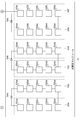
- FIG. 2 shows the configuration of the solar cell module 10.
- the solar cell module 10 includes a cell group 50 and a bypass diode 54.
- the cell group 50 is a general term for the first cell group 50a, the second cell group 50b, the third cell group 50c, the fourth cell group 50d, the fifth cell group 50e, and the sixth cell group 50f.
- the bypass diode 54 is a general term for the first bypass diode 54a, the second bypass diode 54b, and the third bypass diode 54c.
- the first cell group 50a includes an eleventh cell 52aa, a twelfth cell 52ab, a thirteenth cell 52ac, a fourteenth cell 52ad, and a fifteenth cell 52ae.
- the second cell group 50b includes a 21st cell 52ba, a 22nd cell 52bb, a 23rd cell 52bc, a 24th cell 52bd, and a 25th cell 52be.
- the third cell group 50c includes a 31st cell 52ca, a 32nd cell 52cb, a 33rd cell 52cc, a 34th cell 52cd, and a 35th cell 52ce.
- the fourth cell group 50d includes a 41st cell 52da, a 42nd cell 52db, a 43rd cell 52dc, a 44th cell 52dd, and a 45th cell 52de.
- the fifth cell group 50e includes a 51st cell 52ea, a 52nd cell 52eb, a 53rd cell 52ec, a 54th cell 52ed, and a 55th cell 52ee.
- the sixth cell group 50f includes a 61st cell 52fa, a 62nd cell 52fb, a 63rd cell 52fc, a 64th cell 52fd, and a 65th cell 52fe.
- the eleventh cell 52aa, the twelfth cell 52ab, and the like are collectively referred to as the cell 52.
- “six” cell groups 50 of the first cell group 50a to the sixth cell group 50f are connected in series.
- “five” cells 52 are connected in series.
- the number of cell groups 50 connected in series and the number of cells 52 connected in series are not limited to these.
- a bypass diode 54 is connected in parallel to the two cells 52.
- the first bypass diode 54a is connected in parallel to the first cell group 50a and the second cell group 50b.
- the bypass diode 54 is arranged as a countermeasure against the hot spot phenomenon.
- the hot spot phenomenon is a phenomenon in which when an object such as a fallen leaf adheres to the surface of the solar cell and becomes a shadow, the portion generates heat, and the cell 52 may be damaged thereby. This is because, since the cells 52 are connected in series, the generated current flows also in the cell 52 with a small amount of power generation, but since the shadowed cell 52 becomes a resistor, when the current passes therethrough This is because “heat” is generated. Moreover, even if it does not lead to damage, the non-power generation cell 52 becomes a resistor, and the power generated by the other cells 52 is consumed, resulting in a problem that the power generation amount is reduced. The amount of power generation is reduced more than the shaded part does not generate power. In order to reduce the influence of such a phenomenon, the bypass diode 54 is connected in parallel with the cell 52. Returning to FIG.
- the control unit 22 controls the operation of the power control apparatus 100.
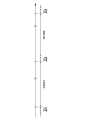
- FIG. 3 shows the operation timing of the power control apparatus 100 controlled by the control unit 22.
- the control unit 22 alternately switches between the set period and the update period as the operation timing of the power control apparatus 100.
- the length of the set period is defined to be shorter than the length of the update period. For example, of the 24 hours, several minutes are set as the set period, and the rest are set as the update period.
- the processing in the setting period and the update period will be described later.
- DC power may not be output from the power control apparatus 100, or the direct current that varies based on the control of the setting period from the power control apparatus 100 may be used. May be configured to output.
- the detection unit 24 and the setting unit 26 operate during the set period, and the update unit 28 operates during the update period. Therefore, the detection unit 24 and the setting unit 26 operate during a period in which the update unit 28 is stopped.
- the operation in the update period will be described.
- the detection unit 24 inputs DC power from the solar cell module 10.
- the detector 24 measures an IV characteristic curve with respect to DC power. Since a known technique may be used for measuring the IV characteristic curve, description thereof is omitted here.
- the detection unit 24 detects the peak of the power value in the IV characteristic curve. More specifically, the detection unit 24 calculates a power-voltage characteristic curve (hereinafter referred to as “PV characteristic curve”) from the IV characteristic curve, and detects the maximum value of the power value while changing V. .
- PV characteristic curve power-voltage characteristic curve
- the detection unit 24 outputs the IV characteristic curve, the PV characteristic curve, and the detected peak to the setting unit 26.
- the setting unit 26 inputs the IV characteristic curve, the PV characteristic curve, and the detected peak from the detection unit 24. When there is one detected peak, the setting unit 26 sets an operating point based on the peak.
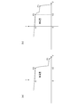
- 4A to 4C show an outline of the operation of the setting unit 26.
- FIG. The upper part of FIG. 4 (a) is an IV characteristic curve when there is one extracted peak
- the lower part of FIG. 4 (a) is a PV characteristic curve when there is one extracted peak. is there. These correspond to the IV characteristic curve and the PV characteristic curve when the hot spot phenomenon does not occur. From these, the setting unit 26 sets P2 at which the power is maximized as an operating point.
- the setting unit 26 determines that the voltage value from the first peak is greater than the first peak.
- the operating point is set based on the second peak that is smaller and has a current value larger than the threshold value.
- the upper part of FIG. 4B is an IV characteristic curve in this case, and the lower part of FIG. 4B is a PV characteristic curve in this case. These correspond to an example of the IV characteristic curve and the PV characteristic curve when the hot spot phenomenon occurs.
- the first peak corresponds to “P1”, and the second peak corresponds to “P2”.
- the two peaks in the lower part of FIG. 4B are maximum values and singular points.
- the setting unit 26 sets “P2” at which the power is maximized as the operating point.
- the setting unit 26 sets the operating point based on the first peak if the current value at the first peak having the maximum voltage value is larger than the threshold value.
- the upper part of FIG. 4C is an IV characteristic curve in this case, and the lower part of FIG. 4C is a PV characteristic curve in this case. These also correspond to examples of the IV characteristic curve and the PV characteristic curve when the hot spot phenomenon occurs.
- the first peak corresponds to “P1”, and the second peak corresponds to “P2”. From the upper part of FIG. 4C, it can be said that since the current value at P1 is larger than the threshold value, the current amount of the cell with a small amount of power generation is large and the temperature rise of the cell with a small amount of power generation is large.
- the setting unit 26 sets “P1” whose power is lower than “P2” where the power is maximum as the operating point. Returning to FIG. The setting unit 26 sets an operating point in the power adjustment unit 20 before the update period starts.
- the operating point of the power adjustment unit 20 is set from the setting unit 26 before switching from the setting period to the update period.
- the power adjustment unit 20 adjusts the DC power from the solar cell module 10 according to the operating point set in the setting unit 26.
- this direct-current power is the solar cell module 10 in which the cell groups 50 are connected in series, and the solar cell module 10 in which the bypass diode 54 is connected in parallel to at least one cell group 50. Power is being generated.
- description is abbreviate
- the power adjustment unit 20 outputs the adjusted DC power to the load 12.
- FIGS. 5 (a)-(b) show the operation of the power control device to be compared. This corresponds to the case where the maximum output point is set as the operating point as before.
- FIG. 5A is an IV characteristic curve when the influence of the shadow or dirt cell is small
- FIG. 5B is an IV characteristic curve when the influence of the shadow or dirt cell is large. is there.
- the operating point is set to “P2”
- the square area surrounded by the origin “0”, I2, P2, and V2 is the power generation amount. Therefore, in FIG. 5 (b), since a current larger than the state of FIG. 5 (a) flows in the cell 52 having a small power generation amount with a reverse bias applied, the possibility of becoming a high temperature state is increased.
- FIGS. 6A to 6B show the operation of the power control apparatus 100.
- FIG. 6 (a)-(b) corresponds to FIGS. 5 (a)-(b). Since the operating point is set to “P2” in FIG. 6A, the power generation amount in FIG. 6A is a square area surrounded by the origin “0”, I2, P2, and V2. On the other hand, since the operating point is set to “P1” in FIG. 6B, the power generation amount in FIG. 6B is a square area surrounded by the origin “0”, I1, P1, and V1. Therefore, in FIG. 6B, since the current 52 of I1 smaller than I2 flows in the cell 52 with a small power generation amount with a reverse bias smaller than the state of FIG. Less likely. Returning to FIG.
- the load 12 is a DC drive type electric device.
- the load 12 is operated by DC power from the power adjustment unit 20.
- the update unit 28 receives the operating point set in the setting unit 26 before switching from the set period to the update period.
- the update unit 28 updates the operating point set in the setting unit 26 over the update period.
- the update unit 28 updates the operating point so that the power value of the AC power is increased by executing a hill climbing method (Hill Climbing Method). This can be said to be a maximum power point tracking method for a peak corresponding to the operating point set in the setting unit 26.
- the update unit 28 sets the updated operating point in the power adjustment unit 20.
- the power adjustment unit 20 adjusts the output of DC power by using the operating point updated in the update unit 28.
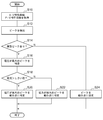
- FIG. 7 is a flowchart showing a setting procedure by the setting unit 26 in the setting period.
- the detection unit 24 acquires an IV characteristic curve and a PV characteristic curve (S10), and detects a peak (S12).
- the setting unit 26 identifies the peak with the maximum voltage (S16). If current> threshold (Y in S18), the setting unit 26 sets the peak with the maximum voltage as the operating point (S20). If current> threshold is not satisfied (N in S18), the setting unit 26 sets the peak at which the power is maximum as the operating point (S22). When there are no plural peaks (N in S14), the setting unit 26 sets the peak as an operating point (S24).
- the operating point if the current value at the first peak having the maximum voltage value is less than the threshold value, the operating point is set based on the second peak having the maximum power value. Therefore, the output power can be increased. Moreover, since the output electric power is increased, the power generation efficiency of the solar cell module can be increased. Further, if the current value at the first peak having the maximum voltage value is larger than the threshold value, the operating point is set based on the first peak, so that the occurrence of the hot spot phenomenon can be suppressed. Moreover, since a temperature rise is suppressed, the lifetime improvement of a solar cell module is realizable. In this case, the output power is smaller than when the operating point is set based on the second peak.
- the bypass diode is connected in parallel to at least one cell group, so that it is possible to reduce the influence of the current inflow to the cells due to the hot spot phenomenon.
- the power adjustment unit 20 is configured to output DC power obtained by adjusting the DC power output from the solar cell module to the load 12.
- the configuration is not limited thereto, and the power adjustment unit 20 may be configured to convert the DC power output from the solar cell module into AC power and output the AC power to the load 12 based on the operating point set by the setting unit 26.
- the power control apparatus 100 having a function of converting such DC power into AC power is called a power conditioner.
- the control provided in the setting unit 26 described in the present embodiment can be applied to the power conditioner.
- FIGS. 4 (b)-(c), 5 (a)-(b), and 6 (a)-(b) are shown as cases where the hot spot phenomenon occurs.
- the present invention is not limited to this.
- three or more peaks may exist.
- the operating point is set based on the peak having the maximum voltage value, and the maximum voltage value is set. If the current value at the peak having the current value is smaller than the threshold value, the operating point is set based on the peak whose voltage value is smaller than the peak value having the maximum voltage value and whose current value is larger than the threshold value.
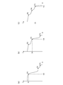
- FIGS. 8A to 8C show the operation of the power control apparatus 100 when there are three peaks.
- the solar cell module having the IV characteristics shown in FIGS. 8A to 8C has at least two cells 52 having a small power generation amount. At least two cells 52 with small power generation amounts are respectively connected in parallel with different bypass diodes.
- the third peak corresponds to “P3”
- the fourth peak corresponds to “P4”
- the fifth peak Corresponds to “P5”.
- the setting unit 26 sets “P5” at which the power is maximized as the operating point.
- the setting unit 26 sets “P4” having a voltage value smaller than “P3” having the maximum voltage value and a current value larger than the threshold value as the operating point.
- the setting unit 26 sets “P3” having the maximum voltage value as the operating point.
Landscapes
- Engineering & Computer Science (AREA)
- Power Engineering (AREA)
- Life Sciences & Earth Sciences (AREA)
- Sustainable Development (AREA)
- Sustainable Energy (AREA)
- Physics & Mathematics (AREA)
- Electromagnetism (AREA)
- General Physics & Mathematics (AREA)
- Radar, Positioning & Navigation (AREA)
- Automation & Control Theory (AREA)
- Control Of Electrical Variables (AREA)
- Photovoltaic Devices (AREA)
Abstract
Description
Claims (5)
- 太陽電池モジュールの出力する直流電力に対する電流-電圧特性曲線において、電力値のピークを検出する検出部と、
前記検出部において複数のピークが検出された場合、(1)複数のピークのうち、最大の電圧値を有した第1ピークでの電流値がしきい値よりも大きければ、第1ピークをもとに動作点を設定し、(2)前記第1ピークでの電流値が前記しきい値以下であれば、複数のピークのうち、前記第1ピークより電圧値が小さくかつ電流値が前記しきい値より大きい第2ピークをもとに動作点を設定する設定部と、
前記設定部において設定した動作点にしたがって、前記太陽電池モジュールの直流電力の出力を調整する電力調整部と、
を備えることを特徴とする電力制御装置。 - 太陽電池モジュールの出力する直流電力に対する電流-電圧特性曲線において、電力値のピークを検出する検出部と、
前記検出部において複数のピークが検出された場合、(1)複数のピークのうち、最大の電圧値を有した第1ピークでの電流値がしきい値よりも大きければ、第1ピークをもとに動作点を設定し、(2)電流値がしきい値以下であれば、複数のピークのうち、最大の電力値を有した第2ピークをもとに動作点を設定する設定部と、
前記設定部において設定した動作点にしたがって、記太陽電池モジュールの直流電力の出力を調整する電力調整部と、
を備えることを特徴とする電力制御装置。 - 前記設定部において設定した動作点を更新する更新部をさらに備え、
前記電力調整部は、前記更新部において更新された動作点を変換に使用し、
前記検出部および前記設定部は、前記更新部が停止する期間において動作することを特徴とする請求項1または2に記載の電力制御装置。 - 前記電力調整部に入力される直流電力は、セル群が直列に接続された前記太陽電池モジュールであって、少なくともひとつのセル群に対してバイパスダイオードが並列に接続された前記太陽電池モジュールにて発電されている請求項1から3のいずれか一項に記載の電力制御装置。
- 太陽電池モジュールの出力する直流電力に対する電流-電圧特性曲線において、電力値のピークを検出する検出部と、
前記検出部において複数のピークが検出された場合、(1)複数のピークのうち、最大の電圧値を有した第1ピークでの電流値がしきい値よりも大きければ、第1ピークをもとに動作点を設定し、(2)前記第1ピークでの電流値が前記しきい値以下であれば、複数のピークのうち、前記第1ピークより電圧値が小さくかつ電流値が前記しきい値より大きい第2ピークをもとに動作点を設定する設定部と、
前記設定部において設定した動作点にしたがって、前記太陽電池モジュールの直流電力を交流電力に変換する電力調整部と、
を備えることを特徴とするパワーコンディショナ。
Priority Applications (4)
| Application Number | Priority Date | Filing Date | Title |
|---|---|---|---|
| CN201580010707.3A CN106062654B (zh) | 2014-02-27 | 2015-01-13 | 功率控制装置和功率调节器 |
| EP15754643.3A EP3112974B1 (en) | 2014-02-27 | 2015-01-13 | Power controller and power conditioner |
| JP2016505012A JP6380817B2 (ja) | 2014-02-27 | 2015-01-13 | 電力制御装置およびパワーコンディショナ |
| US15/183,171 US10186871B2 (en) | 2014-02-27 | 2016-06-15 | Power control apparatus and power conditioner |
Applications Claiming Priority (2)
| Application Number | Priority Date | Filing Date | Title |
|---|---|---|---|
| JP2014037090 | 2014-02-27 | ||
| JP2014-037090 | 2014-02-27 |
Related Child Applications (1)
| Application Number | Title | Priority Date | Filing Date |
|---|---|---|---|
| US15/183,171 Continuation US10186871B2 (en) | 2014-02-27 | 2016-06-15 | Power control apparatus and power conditioner |
Publications (1)
| Publication Number | Publication Date |
|---|---|
| WO2015129147A1 true WO2015129147A1 (ja) | 2015-09-03 |
Family
ID=54008486
Family Applications (1)
| Application Number | Title | Priority Date | Filing Date |
|---|---|---|---|
| PCT/JP2015/000116 Ceased WO2015129147A1 (ja) | 2014-02-27 | 2015-01-13 | 電力制御装置およびパワーコンディショナ |
Country Status (5)
| Country | Link |
|---|---|
| US (1) | US10186871B2 (ja) |
| EP (1) | EP3112974B1 (ja) |
| JP (1) | JP6380817B2 (ja) |
| CN (1) | CN106062654B (ja) |
| WO (1) | WO2015129147A1 (ja) |
Cited By (2)
| Publication number | Priority date | Publication date | Assignee | Title |
|---|---|---|---|---|
| WO2017146074A1 (ja) * | 2016-02-26 | 2017-08-31 | シャープ株式会社 | 太陽電池を用いた電源装置、それを備える通信装置等の電子装置、および看板装置 |
| JP2019146297A (ja) * | 2018-02-16 | 2019-08-29 | 学校法人幾徳学園 | 太陽電池の動作電圧制御装置 |
Families Citing this family (1)
| Publication number | Priority date | Publication date | Assignee | Title |
|---|---|---|---|---|
| CN116430415B (zh) * | 2023-03-28 | 2024-06-21 | 北方雷科(安徽)科技有限公司 | 一种自适应多峰值多门限检测的捕获验证策略方法 |
Citations (4)
| Publication number | Priority date | Publication date | Assignee | Title |
|---|---|---|---|---|
| JP2010219349A (ja) * | 2009-03-17 | 2010-09-30 | National Institute Of Advanced Industrial Science & Technology | 太陽光発電システム |
| US20120126624A1 (en) * | 2010-11-19 | 2012-05-24 | Texas Instruments Incorporated | High efficiency wide load range buck/boost/bridge photovoltaic micro-converter |
| JP2013055132A (ja) * | 2011-09-01 | 2013-03-21 | Hitachi Ltd | 太陽光発電システムの故障診断方法 |
| JP2013105318A (ja) * | 2011-11-14 | 2013-05-30 | Panasonic Corp | 太陽光発電用パワーコンディショナ |
Family Cites Families (10)
| Publication number | Priority date | Publication date | Assignee | Title |
|---|---|---|---|---|
| JP3234358B2 (ja) | 1993-07-13 | 2001-12-04 | 三洋電機株式会社 | インバータの単独運転検出のための出力変調方法 |
| US7969133B2 (en) * | 2008-05-14 | 2011-06-28 | National Semiconductor Corporation | Method and system for providing local converters to provide maximum power point tracking in an energy generating system |
| US8228697B2 (en) * | 2009-07-20 | 2012-07-24 | General Electric Company | Systems, methods, and apparatus for operating a power converter |
| KR101732984B1 (ko) * | 2011-04-12 | 2017-05-08 | 엘지전자 주식회사 | 태양광 모듈 및 그 제어방법 |
| JP5583093B2 (ja) * | 2011-09-21 | 2014-09-03 | シャープ株式会社 | 光発電モジュールおよび光発電モジュールアレイ |
| CN102638197B (zh) * | 2012-04-20 | 2014-11-12 | 浙江昱能科技有限公司 | 太阳能光伏组件及其最大功率点跟踪方法和故障监测方法 |
| CN103516304A (zh) * | 2012-06-18 | 2014-01-15 | 广东旭粤新能源科技有限公司 | 一种光伏电源优化器及其优化方法 |
| JP2014011409A (ja) * | 2012-07-02 | 2014-01-20 | Sony Corp | 発電制御装置および発電制御方法 |
| CN203071590U (zh) * | 2012-12-27 | 2013-07-17 | 梁志刚 | 功率优化装置及太阳能电池板及并网发电系统 |
| CN103425174A (zh) * | 2013-07-29 | 2013-12-04 | 常州佳讯光电产业发展有限公司 | 自适应多峰光伏最大功率跟踪装置及方法 |
-
2015
- 2015-01-13 EP EP15754643.3A patent/EP3112974B1/en active Active
- 2015-01-13 CN CN201580010707.3A patent/CN106062654B/zh active Active
- 2015-01-13 WO PCT/JP2015/000116 patent/WO2015129147A1/ja not_active Ceased
- 2015-01-13 JP JP2016505012A patent/JP6380817B2/ja active Active
-
2016
- 2016-06-15 US US15/183,171 patent/US10186871B2/en active Active
Patent Citations (4)
| Publication number | Priority date | Publication date | Assignee | Title |
|---|---|---|---|---|
| JP2010219349A (ja) * | 2009-03-17 | 2010-09-30 | National Institute Of Advanced Industrial Science & Technology | 太陽光発電システム |
| US20120126624A1 (en) * | 2010-11-19 | 2012-05-24 | Texas Instruments Incorporated | High efficiency wide load range buck/boost/bridge photovoltaic micro-converter |
| JP2013055132A (ja) * | 2011-09-01 | 2013-03-21 | Hitachi Ltd | 太陽光発電システムの故障診断方法 |
| JP2013105318A (ja) * | 2011-11-14 | 2013-05-30 | Panasonic Corp | 太陽光発電用パワーコンディショナ |
Cited By (3)
| Publication number | Priority date | Publication date | Assignee | Title |
|---|---|---|---|---|
| WO2017146074A1 (ja) * | 2016-02-26 | 2017-08-31 | シャープ株式会社 | 太陽電池を用いた電源装置、それを備える通信装置等の電子装置、および看板装置 |
| JPWO2017146074A1 (ja) * | 2016-02-26 | 2018-11-15 | シャープ株式会社 | 太陽電池を用いた電源装置、それを備える通信装置等の電子装置、および看板装置 |
| JP2019146297A (ja) * | 2018-02-16 | 2019-08-29 | 学校法人幾徳学園 | 太陽電池の動作電圧制御装置 |
Also Published As
| Publication number | Publication date |
|---|---|
| JP6380817B2 (ja) | 2018-08-29 |
| US10186871B2 (en) | 2019-01-22 |
| JPWO2015129147A1 (ja) | 2017-03-30 |
| EP3112974A1 (en) | 2017-01-04 |
| US20160294192A1 (en) | 2016-10-06 |
| EP3112974B1 (en) | 2019-01-09 |
| CN106062654B (zh) | 2017-10-24 |
| EP3112974A4 (en) | 2017-04-19 |
| CN106062654A (zh) | 2016-10-26 |
Similar Documents
| Publication | Publication Date | Title |
|---|---|---|
| US9477247B2 (en) | Device and method for global maximum power point tracking | |
| KR101925528B1 (ko) | 태양 전지 설비를 위한 국부화된 파워 포인트 옵티마이저 | |
| Du et al. | A novel solar panel optimizer with self-compensation for partial shadow condition | |
| US9442504B2 (en) | Methods and apparatus for adaptive operation of solar power systems | |
| EP2824533B1 (en) | Photovoltaic system | |
| KR101223611B1 (ko) | 가변 전압 증분을 이용한 섭동 및 관측 방법을 이용하여 최대 전력을 추정하는 태양광 발전 제어 시스템 및 방법 | |
| WO2005112551A2 (en) | Method for compensating for partial shade in photovoltaic power system | |
| KR101160126B1 (ko) | 태양광 발전효율 향상 및 최적화 장치를 갖는 파워플러스 스테이션 태양광 발전시스템 | |
| KR101135990B1 (ko) | 가변 어레이를 이용한 태양광 발전 시스템 | |
| Xu et al. | Proposal for an active PV array to improve system efficiency during partial shading | |
| JP6380817B2 (ja) | 電力制御装置およびパワーコンディショナ | |
| KR101352474B1 (ko) | 직병렬 가변 어레이를 이용한 태양광 발전 시스템 | |
| KR20060044698A (ko) | 태양광 발전 시스템의 부분 그늘 보상 방법 | |
| CN110198073B (zh) | 能源供应系统及能源管理的方法 | |
| Kajiwara et al. | Performance-Improved Maximum Power Point Tracking Control for PV System | |
| JP2019144953A (ja) | 太陽電池制御システム | |
| KR20140028629A (ko) | 태양광 발전 시스템 및 그 제어방법 | |
| KR101349479B1 (ko) | 태양광 발전 장치 및 그 제어방법 | |
| KR102175430B1 (ko) | 태양광 발전 장치 | |
| KR102939604B1 (ko) | 모듈 및 스트링 간 다계층 전력 밸런싱 제어를 위한 태양광 발전 시스템 | |
| KR101360539B1 (ko) | 태양광 발전 시스템 및 그 제어방법 | |
| KR20140093355A (ko) | 스트링 전압 승압기를 포함하는 태양광 발전시스템 | |
| JP2013206352A (ja) | 最大電力点検出方法、および最大電力点検出装置 | |
| JP5912417B2 (ja) | 太陽光発電装置 | |
| CN109787270B (zh) | 用于功率优化的电压转换器及其模式切换方法 |
Legal Events
| Date | Code | Title | Description |
|---|---|---|---|
| 121 | Ep: the epo has been informed by wipo that ep was designated in this application |
Ref document number: 15754643 Country of ref document: EP Kind code of ref document: A1 |
|
| ENP | Entry into the national phase |
Ref document number: 2016505012 Country of ref document: JP Kind code of ref document: A |
|
| NENP | Non-entry into the national phase |
Ref country code: DE |
|
| REEP | Request for entry into the european phase |
Ref document number: 2015754643 Country of ref document: EP |
|
| WWE | Wipo information: entry into national phase |
Ref document number: 2015754643 Country of ref document: EP |