WO2015129230A1 - ドームカメラ - Google Patents
ドームカメラ Download PDFInfo
- Publication number
- WO2015129230A1 WO2015129230A1 PCT/JP2015/000834 JP2015000834W WO2015129230A1 WO 2015129230 A1 WO2015129230 A1 WO 2015129230A1 JP 2015000834 W JP2015000834 W JP 2015000834W WO 2015129230 A1 WO2015129230 A1 WO 2015129230A1
- Authority
- WO
- WIPO (PCT)
- Prior art keywords
- optical system
- correction optical
- dome
- lens
- camera
- Prior art date
- Legal status (The legal status is an assumption and is not a legal conclusion. Google has not performed a legal analysis and makes no representation as to the accuracy of the status listed.)
- Ceased
Links
Images


Classifications
-
- G—PHYSICS
- G02—OPTICS
- G02B—OPTICAL ELEMENTS, SYSTEMS OR APPARATUS
- G02B13/00—Optical objectives specially designed for the purposes specified below
-
- G—PHYSICS
- G02—OPTICS
- G02B—OPTICAL ELEMENTS, SYSTEMS OR APPARATUS
- G02B13/00—Optical objectives specially designed for the purposes specified below
- G02B13/08—Anamorphotic objectives
-
- G—PHYSICS
- G02—OPTICS
- G02B—OPTICAL ELEMENTS, SYSTEMS OR APPARATUS
- G02B13/00—Optical objectives specially designed for the purposes specified below
- G02B13/18—Optical objectives specially designed for the purposes specified below with lenses having one or more non-spherical faces, e.g. for reducing geometrical aberration
-
- G—PHYSICS
- G02—OPTICS
- G02B—OPTICAL ELEMENTS, SYSTEMS OR APPARATUS
- G02B15/00—Optical objectives with means for varying the magnification
- G02B15/14—Optical objectives with means for varying the magnification by axial movement of one or more lenses or groups of lenses relative to the image plane for continuously varying the equivalent focal length of the objective
- G02B15/146—Optical objectives with means for varying the magnification by axial movement of one or more lenses or groups of lenses relative to the image plane for continuously varying the equivalent focal length of the objective having more than five groups
- G02B15/1461—Optical objectives with means for varying the magnification by axial movement of one or more lenses or groups of lenses relative to the image plane for continuously varying the equivalent focal length of the objective having more than five groups the first group being positive
-
- G—PHYSICS
- G02—OPTICS
- G02B—OPTICAL ELEMENTS, SYSTEMS OR APPARATUS
- G02B15/00—Optical objectives with means for varying the magnification
- G02B15/14—Optical objectives with means for varying the magnification by axial movement of one or more lenses or groups of lenses relative to the image plane for continuously varying the equivalent focal length of the objective
- G02B15/16—Optical objectives with means for varying the magnification by axial movement of one or more lenses or groups of lenses relative to the image plane for continuously varying the equivalent focal length of the objective with interdependent non-linearly related movements between one lens or lens group, and another lens or lens group
- G02B15/177—Optical objectives with means for varying the magnification by axial movement of one or more lenses or groups of lenses relative to the image plane for continuously varying the equivalent focal length of the objective with interdependent non-linearly related movements between one lens or lens group, and another lens or lens group having a negative front lens or group of lenses
-
- G—PHYSICS
- G02—OPTICS
- G02B—OPTICAL ELEMENTS, SYSTEMS OR APPARATUS
- G02B26/00—Optical devices or arrangements for the control of light using movable or deformable optical elements
- G02B26/08—Optical devices or arrangements for the control of light using movable or deformable optical elements for controlling the direction of light
- G02B26/0875—Optical devices or arrangements for the control of light using movable or deformable optical elements for controlling the direction of light by means of one or more refracting elements
-
- G—PHYSICS
- G03—PHOTOGRAPHY; CINEMATOGRAPHY; ANALOGOUS TECHNIQUES USING WAVES OTHER THAN OPTICAL WAVES; ELECTROGRAPHY; HOLOGRAPHY
- G03B—APPARATUS OR ARRANGEMENTS FOR TAKING PHOTOGRAPHS OR FOR PROJECTING OR VIEWING THEM; APPARATUS OR ARRANGEMENTS EMPLOYING ANALOGOUS TECHNIQUES USING WAVES OTHER THAN OPTICAL WAVES; ACCESSORIES THEREFOR
- G03B17/00—Details of cameras or camera bodies; Accessories therefor
- G03B17/56—Accessories
- G03B17/561—Support related camera accessories
-
- G—PHYSICS
- G08—SIGNALLING
- G08B—SIGNALLING SYSTEMS, e.g. PERSONAL CALLING SYSTEMS; ORDER TELEGRAPHS; ALARM SYSTEMS
- G08B13/00—Burglar, theft or intruder alarms
- G08B13/18—Actuation by interference with heat, light, or radiation of shorter wavelength; Actuation by intruding sources of heat, light, or radiation of shorter wavelength
- G08B13/189—Actuation by interference with heat, light, or radiation of shorter wavelength; Actuation by intruding sources of heat, light, or radiation of shorter wavelength using passive radiation detection systems
- G08B13/194—Actuation by interference with heat, light, or radiation of shorter wavelength; Actuation by intruding sources of heat, light, or radiation of shorter wavelength using passive radiation detection systems using image scanning and comparing systems
- G08B13/196—Actuation by interference with heat, light, or radiation of shorter wavelength; Actuation by intruding sources of heat, light, or radiation of shorter wavelength using passive radiation detection systems using image scanning and comparing systems using television cameras
- G08B13/19617—Surveillance camera constructional details
- G08B13/19619—Details of casing
-
- H—ELECTRICITY
- H04—ELECTRIC COMMUNICATION TECHNIQUE
- H04N—PICTORIAL COMMUNICATION, e.g. TELEVISION
- H04N23/00—Cameras or camera modules comprising electronic image sensors; Control thereof
- H04N23/50—Constructional details
-
- H—ELECTRICITY
- H04—ELECTRIC COMMUNICATION TECHNIQUE
- H04N—PICTORIAL COMMUNICATION, e.g. TELEVISION
- H04N23/00—Cameras or camera modules comprising electronic image sensors; Control thereof
- H04N23/50—Constructional details
- H04N23/51—Housings
-
- H—ELECTRICITY
- H04—ELECTRIC COMMUNICATION TECHNIQUE
- H04N—PICTORIAL COMMUNICATION, e.g. TELEVISION
- H04N23/00—Cameras or camera modules comprising electronic image sensors; Control thereof
- H04N23/60—Control of cameras or camera modules
- H04N23/69—Control of means for changing angle of the field of view, e.g. optical zoom objectives or electronic zooming
-
- H—ELECTRICITY
- H04—ELECTRIC COMMUNICATION TECHNIQUE
- H04N—PICTORIAL COMMUNICATION, e.g. TELEVISION
- H04N23/00—Cameras or camera modules comprising electronic image sensors; Control thereof
- H04N23/50—Constructional details
- H04N23/55—Optical parts specially adapted for electronic image sensors; Mounting thereof
Definitions
- This disclosure relates to a dome camera.
- Patent Document 1 discloses a surveillance camera device having a dome cover and a camera body.
- the surveillance camera device includes a dome cover that is a part of a spherical shape divided into two or more parts, a camera body that captures a subject, and a tilt mechanism that rotates the camera body. Thereby, a subject above the horizontal plane can be photographed.
- a dome camera in the present disclosure is rotatable, and includes a camera body having a lens system and an imaging device, a correction optical system having a curved surface shape, and a dome cover that covers the camera body and the correction optical system.
- the correction optical system performs at least one of tilt, eccentricity, and rotation according to the rotation angle of the camera body.
- FIG. 6 is a layout diagram of lens systems provided in the camera body in the first to fifth embodiments.
- 2 is a perspective view of a correction optical system according to Embodiment 1.
- FIG. It is the figure which looked at the correction
- FIG. 6 is a lateral aberration diagram in a state where correction is performed by a correction optical system and a state where correction is not performed at the telephoto end of the dome camera according to Embodiment 1; It is explanatory drawing which shows the relationship of the operation
- FIG. 10 is a lateral aberration diagram in a state where correction is performed by a correction optical system and a state where correction is not performed at the telephoto end of the dome camera according to Embodiment 2. It is explanatory drawing which shows the relationship of the operation
- FIG. 10 is a lateral aberration diagram in a state where correction is performed by a correction optical system and a state where correction is not performed at the telephoto end of the dome camera according to Embodiment 3.
- FIG. 10 is a lateral aberration diagram in a state where correction is performed by a correction optical system and a state where correction is not performed at a telephoto end of a dome camera according to Embodiment 4. It is explanatory drawing which shows the relationship of the operation
- FIG. 10 is a lateral aberration diagram in a corrected state and a non-corrected state at the telephoto end of the dome camera according to Embodiment 5; It is explanatory drawing which shows the operation
- FIG. 10 is a layout diagram of lens systems provided in a camera body in a sixth embodiment.
- FIG. 16 is a lateral aberration diagram in a state where correction is performed by a correction optical system and a state where correction is not performed, at a telephoto end of a dome camera according to Embodiment 6.
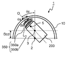
- FIG. 20 is an explanatory diagram showing the relationship between the camera body and the correction optical system in a dome camera according to Embodiment 7, and showing oblique shooting. It is explanatory drawing which shows the relationship of the operation
- FIG. 10 is a layout diagram of lens systems provided in a camera body in a seventh embodiment.
- FIG. 16 is a lateral aberration diagram in a state where correction is performed by a correction optical system and a state where correction is not performed at a telephoto end of a dome camera according to Embodiment 7.
- the fact that the correction optical system performs at least one of tilt, eccentricity, and rotation is also referred to as movement of the correction optical system.
- the tilt amount, tilt angle, rotation angle, decentration amount, and the like of the correction optical system are also referred to as the movement amount of the correction optical system.
- Embodiment 1 Hereinafter, the dome camera of Embodiment 1 will be described with reference to the drawings.
- the first embodiment a case of a dome camera used for a surveillance camera or the like is illustrated.
- the dome camera 1 according to the first embodiment includes a camera body 200, a dome cover 10, and a movable correction optical system 310.
- the camera body 200 inside the dome cover 10 has a lens system and an image sensor inside.
- the lens system is a zoom lens system.
- the dome cover 10 has a cup shape as a whole, and includes a substantially hemispherical spherical surface portion 10a and a cylindrical cylindrical portion 10b.
- the spherical surface portion 10a and the cylindrical portion 10b are integrally molded, but may be joined after being molded separately.
- the cylindrical portion 10b is not limited to a columnar shape, and may be a conical shape.
- the correction optical system 310 is for optically correcting the light beam passing through the cylindrical portion 10b of the dome cover 10.
- the correction optical system 310 is configured to be movable between a retracted state and a correction state.
- the retracted state is a state in which the correction optical system 310 is moved to a position that is not affected by the light incident on the lens system of the camera body 200 according to the rotation angle ⁇ c of the camera body 200.
- the correction state is a state in which the correction optical system 310 has moved to a position between the dome cover 10 and the camera body 200. Details of the operation of the correction optical system 310 will be described later.
- the dome camera 1 includes a pan motor (not shown) and a tilt motor (not shown).
- the camera body 200 can be rotated in the pan direction and the tilt direction with respect to the dome cover 10 by a pan motor and a tilt motor.
- the operations of the pan motor and the tilt motor are controlled by a control unit such as a microcomputer.
- the dome camera 1 includes a correction optical system actuator (not shown) that drives the correction optical system 310.
- the operation of the correction optical system actuator is controlled by a control unit such as a microcomputer.
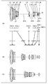
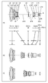
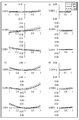
- FIG. 2 is a layout diagram of the lens system according to Embodiment 1, and represents the lens system in an infinitely focused state.
- the lens system of FIG. 2 is also used in the camera body 200 in the second to fifth embodiments.
- FIG. 2 (a) in FIG. 2 represents the lens configuration at the wide-angle end, (b) at the intermediate position, and (c) at the telephoto end.
- the wide angle end in FIG. 2A refers to the shortest focal length state.
- Focal length at the shortest focal length condition is f W.
- the intermediate position in FIG. 2B refers to an intermediate focal length state.
- the focal length f M in the intermediate focal length state is defined by the following equation.
- the telephoto end in FIG. 2C refers to the longest focal length state.
- Focal length at the longest focal length condition is f T.
- the broken line arrows provided between (a) and (b) in FIG. 2 connect the positions of the lens groups in the wide-angle end, the intermediate position, and the telephoto end in order from the top. Is a straight line obtained by The wide-angle end and the intermediate position, and the intermediate position and the telephoto end are simply connected by a straight line, which is different from the actual movement of each lens group.
- FIG. 2 shows a direction in which a later-described fifth lens group G5 moves during focusing from the infinite focus state to the close object focus state.
- FIG. 2A since the reference numerals of the respective lens groups are described, for convenience, an arrow indicating focusing is attached to the lower part of the reference numerals of the fifth lens group G5. However, in each zooming state, focusing is performed. The direction in which the fifth lens group G5 moves at this time will be specifically described later.
- the lens system includes, in order from the object side to the image side, a first lens group G1 having a positive power, a second lens group G2 having a negative power, an aperture stop, and a third lens having a positive power.
- the lens system When zooming from the wide-angle end to the telephoto end, the lens system is configured such that the distance between the lens groups, that is, the distance between the first lens group G1 and the second lens group G2, and the distance between the second lens group G2 and the third lens group G3.
- the interval, the interval between the third lens group G3 and the fourth lens group G4, the interval between the fourth lens group G4 and the fifth lens group G5, and the interval between the fifth lens group G5 and the sixth lens group G6 are all.
- Each lens group moves in a direction along the optical axis so as to change.
- an asterisk * attached to a specific surface indicates that the specific surface is an aspherical surface.
- a symbol (+) and a symbol ( ⁇ ) attached to a symbol of each lens group correspond to a power symbol of each lens group.
- the straight line described on the rightmost side represents the position of the image plane S.
- the first lens group G1 includes, in order from the object side to the image side, a negative meniscus first lens element L1 having a convex surface facing the object side, and a convex surface facing the object side.
- a second lens element L2 having a positive meniscus shape facing the surface
- a third lens element L3 having a positive meniscus shape having a convex surface facing the object side
- a fourth lens element L4 having a positive meniscus shape having a convex surface facing the object side.
- the first lens element L1 and the second lens element L2 are cemented.
- the second lens group G2 includes, in order from the object side to the image side, a negative meniscus fifth lens element L5 having a convex surface facing the object side, a biconcave sixth lens element L6, and a biconvex first lens element L6. 7 lens element L7 and biconcave eighth lens element L8.
- the object side surface and the image side surface of the sixth lens element L6 are aspheric.
- the third lens group G3 includes, in order from the object side to the image side, an aperture stop A and a positive meniscus ninth lens element L9 with a convex surface facing the object side.
- the image side surface of the ninth lens element L9 is aspheric.
- the fourth lens group G4 includes, in order from the object side to the image side, a biconvex tenth lens element L10, a biconvex eleventh lens element L11, and a negative meniscus first lens element with a convex surface facing the image side. 12 lens elements L12. Among these, the eleventh lens element L11 and the twelfth lens element L12 are cemented. The object side surface and the image side surface of the tenth lens element L10 are aspheric.
- the fifth lens group G5 comprises solely a bi-concave thirteenth lens element L13.
- the sixth lens group G6 comprises solely a biconvex fourteenth lens element L14.
- the first lens group G1, the aperture stop A, the third lens group G3, and the sixth lens group G6 do not move, and the second lens group G2
- the first lens group G4 and the fifth lens group G5 move monotonously to the image side, and move to the object side. That is, during zooming, the distance between the first lens group G1 and the second lens group G2 and the distance between the fifth lens group G5 and the sixth lens group G6 increase, and the second lens group G2 and the third lens group G3. And the distance between the third lens group G3 and the fourth lens group G4 are decreased, and the distance between the fourth lens group G4 and the fifth lens group G5 is changed. Move along each.
- the fifth lens group G5 which is a focusing lens group, moves to the image side along the optical axis in any zooming state.
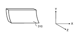
- FIG. 3A and 3B are explanatory diagrams of the correction optical system 310 according to the first embodiment.
- FIG. 3A is a perspective view of the correction optical system 310
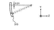
- FIG. 3B is a view of the correction optical system 310 viewed from the Y axis and Z axis vertical directions.
- the correction optical system 310 in the first embodiment is configured by a single optical element having a cylindrical shape.
- the correction optical system 310 has a curvature only in the Y-axis direction (vertex direction), and the curvature in the X-axis direction (perpendicular to the vertex direction) is infinite.
- the correction optical system 310 has a shape with different curvatures in the X-axis direction and the Y-axis direction. Further, in the correction optical system 310, a surface corresponding to the subject side and a surface corresponding to the image surface side in the camera body 200 are decentered in the Y-axis direction shown in FIG. 3B.
- the correction optical system 310 includes a light shielding portion 311 at the end of the dome cover side surface on the dome zenith side (Y-axis direction).
- the light shielding unit 311 can be provided by printing, in Embodiment 1, a frame that holds the optical element of the correction optical system 310 is used as the light shielding unit 311.
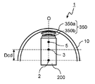
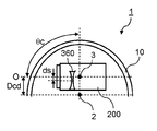
- FIG. 1 is a diagram illustrating a schematic cross section of the dome camera 1 according to the first embodiment, and is an explanatory diagram illustrating an operation relationship between the camera body 200 and the correction optical system 310.
- FIG. 1A shows the dome cover 10 when shooting in the zenith direction.
- FIG. 1B shows the oblique photographing in which the camera body 200 is rotated by ⁇ c with respect to the photographing state in the zenith direction of FIG. 1A.
- FIG. 1C shows the time of horizontal photographing that is perpendicular to the zenith direction of the dome cover 10.
- FIG. 1D shows a case where the camera body 200 is rotated by ⁇ c in the direction opposite to the zenith direction with respect to the horizontal shooting state of FIG.
- the camera body 200 rotates about the rotation center 3 of the camera body 200 as a central axis.
- the rotation center 3 of the camera body 200 is located in the zenith direction of the dome cover 10 with respect to the spherical center position of the dome cover 10 (the curvature center 2 of the spherical surface portion 10a).
- the correction optical system 310 In the region where the zooming position of the lens system is in the intermediate position from the wide-angle end, the correction optical system 310 is retracted outside the imaging range of the camera body 200 regardless of the rotation angle ⁇ c of the camera body 200. On the other hand, in the region where the zooming position of the lens system is from the intermediate position to the telephoto end, the correction optical system 310 is inserted into the imaging range of the camera body 200 according to the rotation angle ⁇ c of the camera body 200.
- the correction optical system 310 is retracted outside the shooting range of the camera body 200.
- the angle at which the light beam of the camera body 200 passes through the cylindrical portion 10b, that is, the rotation angle ⁇ c of the camera body 200 exceeds 85 ° the correction optical system 310 is inserted into the shooting range of the camera body 200.
- the correction optical system 310 When ⁇ c is smaller than 90 °, the correction optical system 310 is decentered in the direction opposite to the zenith direction of the dome cover 10, and the optical axis O of the camera body 200, the cylindrical portion 10 b and the spherical portion 10 a of the dome cover 10. It decenters so that the line connecting the boundary and the end of the correction optical system 310 on the zenith side is parallel. That is, in accordance with the change of ⁇ c, the optical axis O and the line connecting the boundary between the cylindrical portion 10b and the spherical surface portion 10a of the dome cover 10 and the end portion on the zenith side of the correction optical system 310 are parallel to each other.
- the correction optical system 310 is decentered. In FIG. 1, the amount of decentration when the correction optical system 310 is decentered is represented by ds.
- the dome camera 1 According to the dome camera 1 according to the first embodiment, even when the camera body 200 captures a subject in the direction of the cylindrical portion 10b of the dome cover 10, the decentration coma aberration, the one-sided blur, the astigmatism, and the like are improved, and the high quality is achieved. It is possible to take a simple image.
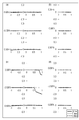
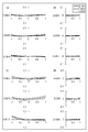
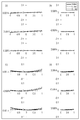
- 4 (a) and 4 (c) are lateral aberration diagrams in the meridional direction
- FIGS. 4 (b) and 4 (d) are lateral aberration diagrams in the sagittal direction
- the solid line is the d-line (d-line).
- the short broken line is the characteristic of the F line (F-line), and the long broken line is the characteristic of the C line (C-line).
- F-line the characteristic of the F line
- C-line the characteristic of the C line
- FIG. 4C the image plane tilt is observed on the ⁇ 1.00 FA and 0.00FA pupil 1.0 side, but in FIG. 4A, the image plane tilt is improved. I understand that.
- the cylindrical portion 10b of the dome cover 10 has different curvatures in the X-axis direction (perpendicular to the apex direction) and the Y-axis direction (vertex direction). Therefore, the correction optical system 310 corrects the difference between the curvature in the X-axis direction and the curvature in the Y-axis direction so that the imaging positions in the X-axis direction and the Y-axis direction passing through the cylindrical portion 10b are the same, and the cylindrical portion The tilt of the image plane in the meridional direction of the light beam passing through 10b is corrected. 4 (a), (b), (c), and (d) pupils in the lateral aberration diagrams, the position of the upper ray at each angle of view, the position of the lower ray at -1, and the position of the chief ray Is set to 0.
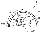
- FIG. 5A to FIG. 5D are diagrams showing a schematic cross section of the dome camera 1 according to the second embodiment, and are explanatory diagrams showing the relationship between the operation of the camera body 200 and the correction optical system 320.
- the shape of the correction optical system 320 is different from that in the first embodiment, and the shape of the lens system inside the camera body 200 and the shape of the dome cover 10 are the same as those in the first embodiment.
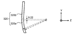
- FIGS. 6A and 6B are explanatory diagrams of the correction optical system 320 in the second embodiment.
- 6A is a perspective view of the correction optical system 320
- FIG. 6B is a view of the correction optical system 320 as viewed from the Y axis and Z axis vertical directions.
- the correction optical system 320 in the second embodiment is composed of one optical element including a curved surface portion 320a and a flat surface portion 320b.
- the curved surface portion 320a has a cylindrical shape as in the first embodiment.
- the curved surface portion 320a has a curvature only in the Y-axis direction (vertex direction), and the curvature in the X-axis direction (perpendicular to the vertex direction) is infinite. That is, the curved surface portion 320a has a shape with different curvatures in the X-axis direction and the Y-axis direction. Further, in the curved surface portion 320a, a surface corresponding to the subject side in the camera body 200 and a surface corresponding to the image surface side are decentered in the Y-axis direction shown in FIG. 6B.
- the planar portion 320b has an infinite curvature in both the X-axis direction and the Y-axis direction. That is, the flat part 320b has a flat plate shape.
- FIG. 5A shows the dome cover 10 when shooting in the zenith direction.
- FIG. 5B shows the oblique photographing when the camera body 200 is rotated by ⁇ c with respect to the photographing state in the zenith direction of FIG. 5A.
- FIG. 5C shows the time of horizontal photographing that is perpendicular to the zenith direction of the dome cover 10.
- FIG. 5D shows a reverse zenith direction oblique photographing in which the camera body 200 is rotated by ⁇ c in a direction opposite to the zenith direction with respect to the horizontal photographing state of FIG. 5C.
- the camera body 200 rotates about the rotation center 3 of the camera body 200 as a central axis.
- the rotation center 3 of the camera body 200 is located in the zenith direction of the dome cover 10 with respect to the spherical center position of the dome cover 10 (the curvature center 2 of the spherical surface portion 10a).
- the correction optical system 320 In the region where the zooming position of the lens system is in the middle position from the wide-angle end, the correction optical system 320 is retracted out of the shooting range of the camera body 200 regardless of the rotation angle ⁇ c of the camera body 200.
- the correction optical system 320 corresponds to the rotation angle ⁇ c of the camera body 200 by the rotation angle ⁇ s about the correction optical system rotation center 4. It is rotated and inserted into the shooting range of the camera body 200.
- the correction optical system 320 when the rotation angle ⁇ c of the camera body 200 is 0 to 85 °, the correction optical system 320 is retracted outside the shooting range of the camera body 200. As shown in FIGS. 5A and 5B, in the second embodiment, the correction optical system 320 is retracted along the side of the camera body 200. When the angle at which the cylindrical portion 10 b enters the angle of view of the camera body 200, that is, when the rotation angle ⁇ c of the camera body 200 exceeds 85 °, the correction optical system 320 is inserted into the shooting range of the camera body 200.
- the rotation in the correction optical system 320 means a case where the correction optical system rotation center 4 is at a position different from the correction optical system 320.
- the optical axis O of the camera body 200 is parallel to the line connecting the boundary between the cylindrical portion 10b and the spherical surface portion 10a of the dome cover 10 and the boundary between the curved surface portion 320a and the flat surface portion 320b of the correction optical system 320.
- the correction optical system 320 rotates.
- the optical axis O and a line connecting the boundary between the cylindrical portion 10b and the spherical surface portion 10a of the dome cover 10 and the boundary between the curved surface portion 320a and the flat surface portion 320b of the correction optical system 320 are parallel.
- the correction optical system 320 rotates.
- 7A and 7C are lateral aberration diagrams in the meridional direction
- FIGS. 7B and 7D are lateral aberration diagrams in the sagittal direction
- the solid line is the d-line (d-line).
- the short broken line is the characteristic of the F line (F-line), and the long broken line is the characteristic of the C line (C-line).
- image plane tilt is observed on the ⁇ 1.00 pupil side of ⁇ 0.50FA and 0.00FA, but in FIG. 7A, the image plane tilt is improved. I understand that.
- the cylindrical portion 10b of the dome cover 10 has different curvatures in the X-axis direction (perpendicular to the apex direction) and the Y-axis direction (vertex direction). Therefore, the correction optical system 320 corrects the difference between the curvature in the X-axis direction and the curvature in the Y-axis direction so that the imaging positions in the X-axis direction and the Y-axis direction passing through the cylindrical portion 10b are the same, and the cylindrical portion The tilt of the image plane in the meridional direction of the light beam passing through 10b is corrected. Note that the lateral aberration in the meridional direction of the pupil 0.4 of ⁇ 0.50FA in FIG.
- the light shielding unit 321 is provided on the surface of the correction optical system 320 on the dome cover side.
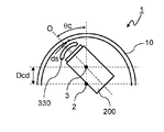
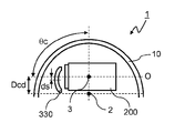
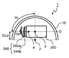
- FIGS. 8A to 8D are diagrams illustrating schematic cross sections of the dome camera 1 according to the third embodiment, and are explanatory diagrams illustrating the relationship between the operation of the camera body 200 and the correction optical system 330.
- FIG. The dome camera 1 according to Embodiment 3 includes a camera body 200, a dome cover 10, and a correction optical system 330.
- the correction optical system 330 is a decentering correction optical system, and is composed of one optical element.
- the camera body 200 inside the dome cover 10 has a lens system and an image sensor inside.
- the configuration of the lens system is the same as that of Embodiment 1, and the lens system is a zoom lens system.
- the dome cover 10 has a substantially hemispherical shape, and the curvature radius on the outer side (front surface) and the curvature radius on the inner side (rear surface) of the dome cover are different.
- the dome cover 10 has spherical surfaces on the front surface side and the back surface side, but it is beneficial that the thickness of the dome cover 10 is the smallest at the zenith portion of the dome cover 10 and increases as the distance from the zenith portion increases. This is because when the camera body 200 is tilted, the center of curvature 2 of the dome cover 10 and the rotation center 3 of the camera body 200 are separated from each other, so that aberration occurs due to the deviation between the dome cover 10 and the optical axis O. This is because this aberration can be corrected.
- the correction optical system 330 optically corrects the light beam that passes through the dome cover 10.
- the correction optical system 330 is decentered perpendicularly to the optical axis according to the rotation angle ⁇ c of the camera body 200. The operation of the correction optical system 330 will be described in detail later.
- the correction optical system 330 in the third embodiment has a positive power and has a meniscus shape.
- FIG. 8A shows the dome cover 10 when shooting in the zenith direction.
- FIG. 8B shows the oblique photographing in which the camera body 200 is rotated by ⁇ c with respect to the photographing state in the zenith direction of FIG. 8A.
- FIG. 8C shows the time of horizontal photographing that is perpendicular to the zenith direction of the dome cover 10.
- FIG. 8D shows a time when the camera body 200 is rotated obliquely in the reverse zenith direction by ⁇ c in the direction opposite to the zenith direction with respect to the horizontal shooting state in FIG. 8C.
- the camera body 200 rotates about the rotation center 3 of the camera body 200 as a central axis.
- the rotation center 3 of the camera body 200 is located in the zenith direction of the dome cover 10 with respect to the spherical center position (curvature center 2) of the dome cover 10.
- the optical axis O of the camera body 200 passes through the center of the correction optical system 330 as shown in FIG. 8A. That is, the correction optical system 330 is not decentered.
- the zooming position of the lens system is as follows in the region from the middle position to the telephoto end.
- the center of the correction optical system 330 is located on the optical axis O when the camera body 200 is photographing the zenith direction of the dome cover 10.
- the correction optical system 330 is decentered perpendicularly to the optical axis O in the direction opposite to the zenith direction of the dome cover 10.
- the rotation angle ⁇ c of the camera body 200 is 90 °
- the absolute value of the decentering amount ds of the correction optical system 330 is the largest.
- FIG. 8D when ⁇ c exceeds 90 °, the absolute value of the decentering amount ds of the correction optical system 330 decreases.
- FIGS. 9A and 9C are transverse aberration diagrams in the meridional direction
- FIGS. 9B and 9D are lateral aberration diagrams in the sagittal direction
- the solid line is the d-line (d-line).
- the short broken line is the characteristic of the F line (F-line), and the long broken line is the characteristic of the C line (C-line).
- Each aberration recognized in (c) and (d) of FIG. 9 is improved in (a) and (b) of FIG. 9, and in particular, coma is improved by decentering the correction optical system 330. You can see that
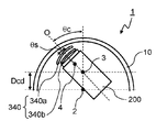
- FIG. 4 (Embodiment 4) [4-1. Constitution] 10A to 10D are diagrams showing a schematic cross section of the dome camera 1 according to Embodiment 4, and are explanatory diagrams showing the relationship between the operation of the camera body 200 and the correction optical system 340.
- FIG. The dome camera 1 according to the fourth embodiment includes a camera body 200, a dome cover 10, and a correction optical system 340.
- the correction optical system 340 includes a movable correction optical system 340a and a fixed correction optical system 340b adjacent to the camera main body 200 side of the movable correction optical system 340a.
- the camera body 200 inside the dome cover 10 has a lens system and an image sensor inside.
- the configuration of the lens system is the same as that of Embodiment 1, and the lens system is a zoom lens system.
- the dome cover 10 is substantially hemispherical.
- the movable correction optical system 340a rotates about the correction optical system rotation center 4 in accordance with the rotation angle ⁇ c of the camera body 200.
- the operation of the movable correction optical system 340a will be described in detail later.
- the movable correction optical system 340a in the fourth embodiment has negative power and has a meniscus shape.
- the fixed correction optical system 340b has a positive power and has a meniscus shape.
- FIG. 10A shows the dome cover 10 when shooting in the zenith direction.
- FIG. 10B shows the oblique photographing in which the camera body 200 is rotated by ⁇ c with respect to the photographing state in the zenith direction in FIG. 10A.
- FIG. 10C shows the time of horizontal photographing that is perpendicular to the zenith direction of the dome cover 10.
- FIG. 10D shows a time when the camera body 200 is rotated by ⁇ c in a direction opposite to the zenith direction with respect to the horizontal shooting state of FIG.
- the camera body 200 rotates about the rotation center 3 of the camera body 200 as a central axis.
- the rotation center 3 of the camera body 200 is located in the zenith direction of the dome cover 10 with respect to the spherical center position (curvature center 2) of the dome cover 10.
- the correction optical system rotation center 4 passes through the optical axis O of the camera body 200 as shown in FIG. 10A.
- the zooming position of the lens system is as follows in the region from the middle position to the telephoto end.
- the correction optical system rotation center 4 is located on the optical axis O, and the movable correction optical system 340a is Does not rotate.
- the movable correction optical system 340a rotates about the correction optical system rotation center 4 in the direction opposite to the zenith direction.
- the rotation angle ⁇ s of the movable correction optical system 340a is 0 ° when the shooting direction of the camera body 200 is the zenith direction.
- the rotation angle ⁇ s of the movable correction optical system 340a increases.
- ⁇ c is 90 °
- ⁇ s is the largest.
- FIG. 10D when ⁇ c exceeds 90 °, ⁇ s decreases.
- 11A and 11C are lateral aberration diagrams in the meridional direction
- FIGS. 11B and 11D are lateral aberration diagrams in the sagittal direction
- the solid line is the d-line (d-line).
- the short broken line is the characteristic of the F line (F-line), and the long broken line is the characteristic of the C line (C-line).
- Each aberration recognized in (c) and (d) of FIG. 11 is improved in (a) and (b) of FIG. 11.
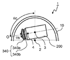
- FIG. 5 The dome camera 1 according to Embodiment 5 includes a camera body 200, a dome cover 10, and a correction optical system 350.
- the correction optical system 350 includes a movable correction optical system 350a, and a fixed correction optical system 350b adjacent to the camera body 200 side of the movable correction optical system 350a.
- the camera body 200 inside the dome cover 10 has a lens system and an image sensor inside.
- the configuration of the lens system is the same as that of Embodiment 1, and the lens system is a zoom lens system.
- the dome cover 10 is substantially hemispherical.
- the movable correction optical system 350a rotates about the correction optical system rotation center 5 and decenters according to the rotation angle ⁇ c of the camera body 200.
- the operation of the movable correction optical system 350a will be described in detail later.
- the movable correction optical system 350a in the fifth embodiment has a positive power and has a meniscus shape.
- the fixed correction optical system 350b has a negative power and has a meniscus shape.
- FIG. 12A shows the dome cover 10 when shooting in the zenith direction.
- FIG. 12B shows the oblique photographing in which the camera body 200 is rotated by ⁇ c with respect to the photographing state in the zenith direction of FIG. 12A.
- FIG. 12C shows the time of horizontal photographing that is perpendicular to the zenith direction of the dome cover 10.
- FIG. 12D shows a time when the camera body 200 is rotated by ⁇ c in a direction opposite to the zenith direction in the horizontal shooting state of FIG.
- the camera body 200 rotates about the rotation center 3 of the camera body 200 as a central axis.
- the rotation center 3 of the camera body 200 is located in the zenith direction of the dome cover 10 with respect to the spherical center position (curvature center 2) of the dome cover 10.
- the correction optical system rotation center 5 is located on the optical axis O of the camera body 200 regardless of the rotation angle ⁇ c of the camera body 200. That is, the movable correction optical system 350a does not rotate or decenter.
- the zooming position of the lens system is as follows in the region from the middle position to the telephoto end.
- the correction optical system rotation center 5 is located on the optical axis O, and the movable correction optical system 350a is , Do not rotate and eccentric.
- the movable correction optical system 350a rotates about the correction optical system rotation center 5.
- the dome cover 10 is rotated in the zenith direction by an angle ⁇ s, and is decentered by a decentering amount ds in a direction perpendicular to the optical axis O direction and opposite to the zenith direction.
- ⁇ c is 90 °
- ⁇ s is the largest.
- the rotation angle ⁇ s decreases at the time when ⁇ c is 90 °.
- ds is proportional to the magnitude of ⁇ c.
- 13A and 13C are lateral aberration diagrams in the meridional direction
- FIGS. 13B and 13D are lateral aberration diagrams in the sagittal direction
- the solid line is the d-line (d-line).
- the short broken line is the characteristic of the F line (F-line), and the long broken line is the characteristic of the C line (C-line).
- the aberrations recognized in (c) and (d) of FIG. 13 are improved in (a) and (b) of FIG. 13, and by rotating and decentering the movable correction optical system 350a, In particular, it can be seen that coma and chromatic aberration are improved.
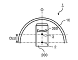
- the dome camera 1 according to the sixth embodiment includes a camera body 200 and a dome cover 10.
- the camera body 200 inside the dome cover 10 has a lens system and an image sensor inside.
- the lens system is a zoom lens system
- the dome cover 10 is substantially hemispherical.
- the dome camera 1 includes a pan motor (not shown) and a tilt motor (not shown).
- the camera body 200 can be rotated in the pan direction and the tilt direction with respect to the dome cover 10 by a pan motor and a tilt motor.
- the operations of the pan motor and the tilt motor are controlled by a control unit such as a microcomputer.
- FIG. 15 is a layout diagram of a lens system according to Embodiment 6, and represents the lens system in an infinitely focused state.
- FIG. 15A shows the lens configuration at the wide-angle end
- FIG. 15B shows the intermediate position
- FIG. 15C shows the lens configuration at the telephoto end.
- the wide-angle end in FIG. 15A refers to the shortest focal length state.
- Focal length at the shortest focal length condition is f W.
- the intermediate position in FIG. 15B refers to an intermediate focal length state.
- the focal length f M in the intermediate focal length state is defined by the following equation.
- the telephoto end in FIG. 15C refers to the longest focal length state.
- Focal length at the longest focal length condition is f T.
- the broken line arrows provided between FIGS. 15A and 15B connect the positions of the lens groups in the wide-angle end, the intermediate position, and the telephoto end in order from the top. Is a straight line obtained by The wide-angle end and the intermediate position, and the intermediate position and the telephoto end are simply connected by a straight line, which is different from the actual movement of each lens group.
- FIG. 15 shows a direction in which a later-described fifth lens group G5 moves during focusing from the infinite focus state to the close object focus state. Since the reference numerals of the lens groups are shown in FIG. 15A, for the sake of convenience, an arrow indicating focusing is attached below the reference numerals of the fifth lens group G5. In each zooming state, focusing is performed. The direction in which the fifth lens group G5 moves at this time will be specifically described later.
- the lens system includes, in order from the object side to the image side, a first lens group G1 having a positive power, a second lens group G2 having a negative power, an aperture stop, and a third lens having a positive power.
- the lens system When zooming from the wide-angle end to the telephoto end, the lens system is configured such that the distance between the lens groups, that is, the distance between the first lens group G1 and the second lens group G2, and the distance between the second lens group G2 and the third lens group G3.
- the interval, the interval between the third lens group G3 and the fourth lens group G4, the interval between the fourth lens group G4 and the fifth lens group G5, and the interval between the fifth lens group G5 and the sixth lens group G6 are all.
- Each lens group moves in a direction along the optical axis so as to change.
- an asterisk * attached to a specific surface indicates that the specific surface is an aspherical surface.
- a symbol (+) and a symbol ( ⁇ ) attached to a symbol of each lens group correspond to a power symbol of each lens group.
- the straight line described on the rightmost side represents the position of the image plane S.
- the first lens group G1 includes, in order from the object side to the image side, a negative meniscus first lens element L1 having a convex surface facing the object side, and a convex surface facing the object side.
- the first lens element L1 and the second lens element L2 are cemented.
- the second lens group G2 includes, in order from the object side to the image side, a negative meniscus fifth lens element L5 having a convex surface facing the object side, a biconcave sixth lens element L6, and a biconvex first lens element L6. 7 lens element L7 and biconcave eighth lens element L8.
- the object side surface and the image side surface of the sixth lens element L6 are aspheric, and the object side surface of the eighth lens element L8 is aspheric.
- the third lens group G3 includes, in order from the object side to the image side, an aperture stop A and a positive meniscus ninth lens element L9 with a convex surface facing the object side.
- the image side surface of the ninth lens element L9 is aspheric.
- the fourth lens group G4 includes, in order from the object side to the image side, a biconvex tenth lens element L10, a biconvex eleventh lens element L11, and a negative meniscus first lens element with a convex surface facing the image side. 12 lens elements L12. Among these, the eleventh lens element L11 and the twelfth lens element L12 are cemented. The object side surface and the image side surface of the tenth lens element L10 are aspheric.
- the fifth lens group G5 comprises solely a bi-concave thirteenth lens element L13.
- the sixth lens group G6 comprises solely a biconvex fourteenth lens element L14.
- the eighth lens element L8 which is a lens element constituting the second lens group G2 is generated by a shift between the dome cover 10 and the optical axis O of the camera body 200, which will be described later. This corresponds to the correction optical system 360 that moves in a direction perpendicular to the optical axis O in order to correct aberration.
- the first lens group G1, the aperture stop A, the third lens group G3, and the sixth lens group G6 do not move, and the second lens group G2
- the first lens group G4 and the fifth lens group G5 move monotonously to the image side, and move to the object side. That is, during zooming, the distance between the first lens group G1 and the second lens group G2 and the distance between the fifth lens group G5 and the sixth lens group G6 increase, and the second lens group G2 and the third lens group G3. And the distance between the third lens group G3 and the fourth lens group G4 are decreased, and the distance between the fourth lens group G4 and the fifth lens group G5 is changed. Move along each.
- the fifth lens group G5 which is a focusing lens group, moves to the image side along the optical axis in any zooming state.
- FIG. 14A to 14D are diagrams showing a schematic cross section of the dome camera 1 according to the sixth embodiment, and are explanatory diagrams showing the relationship between the operation of the camera body 200 and the correction optical system 360.
- FIG. 14A shows the dome cover 10 when shooting in the zenith direction.
- FIG. 14B shows the oblique photographing when the camera body 200 is rotated by ⁇ c with respect to the zenith direction photographing state of FIG. 14A.
- FIG. 14C shows the time of horizontal photographing that is perpendicular to the zenith direction of the dome cover 10.
- FIG. 14D shows a reverse zenith direction oblique photographing in which the camera body 200 is rotated by ⁇ c in a direction opposite to the zenith direction with respect to the horizontal photographing state of FIG. 14C.
- the camera body 200 rotates about the rotation center 3 of the camera body 200 as a central axis.
- the rotation center 3 of the camera body 200 is located in the zenith direction of the dome cover 10 with respect to the spherical center position (curvature center 2) of the dome cover 10.
- the correction optical system 360 is not decentered regardless of the rotation angle ⁇ c of the camera body 200.
- the operation of the correction optical system 360 is as follows.
- the correction optical system 360 is not decentered.
- the correction optical system 360 is accordingly decentered perpendicularly to the optical axis O of the camera body 200 in the direction opposite to the zenith direction. Center).
- the correction optical system 360 is decentered so that the decentering amount ds of the correction optical system 360 is maximized when ⁇ c is 90 °.
- ds gradually decreases.
- the basic operation of the correction optical system 360 is the same as that at the intermediate position, but the eccentric amount ds at the telephoto end is larger than that at the intermediate position. .
- 16A and 16C are lateral aberration diagrams in the meridional direction
- FIGS. 16B and 16D are lateral aberration diagrams in the sagittal direction
- the solid line is the d-line (d-line).
- the short broken line is the characteristic of the F line (F-line), and the long broken line is the characteristic of the C line (C-line).
- F-line F line
- C-line C-line
- the dome camera 1 according to the seventh embodiment includes a camera body 200 and a dome cover 10.
- the camera body 200 inside the dome cover 10 has a lens system and an image sensor inside.
- the lens system is a zoom lens system
- the dome cover 10 is substantially hemispherical.
- the dome camera 1 includes a pan motor (not shown) and a tilt motor (not shown).
- the camera body 200 can be rotated in the pan direction and the tilt direction with respect to the dome cover 10 by a pan motor and a tilt motor.
- the operations of the pan motor and the tilt motor are controlled by a control unit such as a microcomputer.
- FIG. 18 is a layout diagram of a lens system according to Embodiment 7, and represents the lens system in an infinitely focused state.
- FIG. 18A shows a lens configuration at the wide-angle end
- FIG. 18B shows an intermediate position
- FIG. 18C shows a lens configuration at the telephoto end.
- the wide-angle end in FIG. 18A refers to the shortest focal length state.
- Focal length at the shortest focal length condition is f W.
- the intermediate position in (b) of FIG. 18 refers to an intermediate focal length state.
- the focal length f M in the intermediate focal length state is defined by the following equation.
- the telephoto end in FIG. 18C refers to the longest focal length state.
- Focal length at the longest focal length condition is f T.
- the broken line arrows provided between FIGS. 18A and 18B connect the positions of the lens groups in the wide-angle end, the intermediate position, and the telephoto end in order from the top. Is a straight line obtained by The wide-angle end and the intermediate position, and the intermediate position and the telephoto end are simply connected by a straight line, which is different from the actual movement of each lens group.
- FIG. 18 shows a direction in which a later-described fifth lens group G5 moves during focusing from an infinitely focused state to a close object focused state.
- FIG. 18 (a) the reference numerals of the lens groups are described.
- an arrow indicating focusing is attached below the reference numerals of the fifth lens group G5. In each zooming state, focusing is performed. The direction in which the fifth lens group G5 moves at this time will be specifically described later.
- the lens system includes, in order from the object side to the image side, a first lens group G1 having a positive power, a second lens group G2 having a negative power, an aperture stop, and a third lens having a positive power.
- the lens system When zooming from the wide-angle end to the telephoto end, the lens system is configured such that the distance between the lens groups, that is, the distance between the first lens group G1 and the second lens group G2, and the distance between the second lens group G2 and the third lens group G3.
- the interval, the interval between the third lens group G3 and the fourth lens group G4, the interval between the fourth lens group G4 and the fifth lens group G5, and the interval between the fifth lens group G5 and the sixth lens group G6 are all.
- Each lens group moves in a direction along the optical axis so as to change.
- an asterisk * attached to a specific surface indicates that the specific surface is an aspherical surface.
- a symbol (+) and a symbol ( ⁇ ) attached to a symbol of each lens group correspond to a power symbol of each lens group.
- the straight line described on the rightmost side represents the position of the image plane S.
- the first lens group G1 includes, in order from the object side to the image side, a negative meniscus first lens element L1 having a convex surface facing the object side, and a biconvex first lens element L1. It comprises a two-lens element L2, a positive meniscus third lens element L3 with a convex surface facing the object side, and a positive meniscus fourth lens element L4 with a convex surface facing the object side.
- the first lens element L1 and the second lens element L2 are cemented.
- the second lens group G2 includes, in order from the object side to the image side, a negative meniscus fifth lens element L5 having a convex surface facing the object side, a biconcave sixth lens element L6, and a biconvex first lens element L6. 7 lens element L7 and biconcave eighth lens element L8.
- the object side surface and the image surface side of the sixth lens element L6 are aspheric.
- the third lens group G3 includes, in order from the object side to the image side, an aperture stop A and a positive meniscus ninth lens element L9 with a convex surface facing the object side.
- the image side surface of the ninth lens element L9 is aspheric.
- the fourth lens group G4 includes, in order from the object side to the image side, a biconvex tenth lens element L10, a biconvex eleventh lens element L11, and a negative meniscus first lens element with a convex surface facing the image side. 12 lens elements L12. Among these, the eleventh lens element L11 and the twelfth lens element L12 are cemented. The object side surface and the image side surface of the tenth lens element L10 are aspheric.
- the fifth lens group G5 comprises solely a bi-concave thirteenth lens element L13.
- the sixth lens group G6 comprises solely a biconvex fourteenth lens element L14.
- the ninth lens element L9 which is a lens element constituting the third lens group G3, is generated by a deviation between the dome cover 10 and the optical axis O of the camera body 200, which will be described later. This corresponds to the correction optical system 370 that moves in the direction perpendicular to the optical axis O in order to correct the aberration.
- the first lens group G1, the aperture stop A, the third lens group G3, and the sixth lens group G6 do not move, and the second lens group G2
- the first lens group G4 and the fifth lens group G5 move monotonously to the image side, and move to the object side. That is, during zooming, the distance between the first lens group G1 and the second lens group G2 and the distance between the fifth lens group G5 and the sixth lens group G6 increase, and the second lens group G2 and the third lens group G3. And the distance between the third lens group G3 and the fourth lens group G4 are decreased, and the distance between the fourth lens group G4 and the fifth lens group G5 is changed. Move along each.
- the fifth lens group G5 which is a focusing lens group, moves to the image side along the optical axis in any zooming state.
- FIG. 17A to 17D are diagrams showing a schematic cross section of the dome camera 1 according to the seventh embodiment, and are explanatory diagrams showing the relationship between the operation of the camera body 200 and the correction optical system 370.
- FIG. 17A shows the dome cover 10 when shooting in the zenith direction.
- FIG. 17B shows the oblique photographing in which the camera body 200 is rotated by ⁇ c with respect to the photographing state in the zenith direction in FIG. 17A.
- FIG. 17C shows the time of horizontal photographing that is perpendicular to the zenith direction of the dome cover 10.
- FIG. 17D shows a time when the camera body 200 is rotated by ⁇ c in a direction opposite to the zenith direction with respect to the horizontal shooting state of FIG.
- the camera body 200 rotates about the rotation center 3 of the camera body 200 as a central axis.
- the rotation center 3 of the camera body 200 is located in the zenith direction of the dome cover 10 with respect to the spherical center position (curvature center 2) of the dome cover 10.
- the center of the correction optical system 370 is located on the optical axis O when the camera body 200 is photographing the zenith direction of the dome cover 10.
- the correction optical system 370 tilts in the direction opposite to the zenith direction around the top of the object side surface.
- tilt refers to a movement when the rotation center of the correction optical system 370 is positioned on the correction optical system 370.
- the tilt angle ⁇ s of the correction optical system 370 is 0 ° when the shooting direction of the camera body 200 is the zenith direction of the dome cover 10, and the absolute value of ⁇ s increases as the rotation angle ⁇ c of the camera body 200 increases. Increase.
- ⁇ c is 90 °
- the absolute value of ⁇ s is the largest.
- FIG. 17D when ⁇ c exceeds 90 °, the absolute value of ⁇ s decreases.
- 19A and 19C are lateral aberration diagrams in the meridional direction
- FIGS. 19B and 19D are lateral aberration diagrams in the sagittal direction
- the solid line is the d-line (d-line).
- the short broken line is the characteristic of the F line (F-line), and the long broken line is the characteristic of the C line (C-line).
- F-line the characteristic of the F line
- C-line the characteristic of the C line
- the dome cover has a spherical portion and a cylindrical portion
- the correction optical system is disposed between the lens system and the dome cover
- the correction optical system is It is beneficial that the dome camera having a shape with different curvatures in the vertex direction and the direction perpendicular to the vertex direction satisfies the following conditions (1) and (2).
- fgx the combined focal length of the correction optical system and the cylindrical portion of the dome cover in the direction perpendicular to the apex direction
- fgy the combined focal length in the apex direction between the correction optical system and the cylindrical portion of the dome cover
- fd focal length of the spherical surface portion of the dome cover.
- the focal length of the cylindrical portion of the dome cover will be shortened, the in-focus position of the cylindrical portion and the spherical portion will be shifted, and the resulting image will be blurred. There is a fear. If the lower limit of the condition (1) and / or (2) is not reached, the focal length of the cylindrical portion of the dome cover becomes longer, the in-focus position between the cylindrical portion and the spherical portion is shifted, and the resulting image is blurred. There is a fear.
- the dome cover has a spherical surface portion and the correction optical system is disposed between the lens system and the dome cover. ) Is beneficial.
- fs focal length of the correction optical system
- fd focal length of the spherical surface portion of the dome cover.
- the dome camera in which the correction optical system is arranged in the lens group constituting the lens system satisfies the following condition (4). .
- fs focal length of the correction optical system
- fsg the combined focal length of the entire lens group in which the correction optical system is disposed.
- the ghost generated through the boundary surface between the cylindrical portion and the spherical portion of the dome cover and the cylindrical portion are passed by the light shielding portion provided on the surface of the correction optical system on the dome cover side.
- ghosts that do not pass through the correction optical system, ghosts that pass through the spherical portion and pass through the correction optical system, and ghosts generated from the end of the correction optical system in the apex direction are removed.
- the correction optical system to be inserted can suppress the ghost generation range to be small, and the area of the light shielding portion can be reduced when the light shielding portion is provided.
- the light quantity reduction due to can be reduced.
- the optical axis of the camera body, and the line connecting the boundary between the cylindrical and spherical surfaces of the dome cover and the zenith end of the correction optical system are parallel to the rotation angle of the camera body. The correction optical system may be moved so that
- Embodiments 1 and 2 when the zooming position of the lens system is at the wide-angle end, the generated aberration is small even when light passes through the cylindrical portion of the dome cover. Therefore, it is not necessary to use the correction optical system at the wide angle end where the photographing field angle is wide, and the area of the correction optical system can be reduced. Further, when the light shielding portion is provided in front of the correction optical system, it is beneficial to retract the correction optical system because the light beam diameter is small at the wide angle end and the light amount is significantly reduced by the light shielding portion.
- the rotation center of the camera body is located in the zenith direction of the dome cover with respect to the spherical center position (curvature center) of the dome cover.
- the center of curvature of the inner surface is shifted in the zenith direction from the center of curvature of the outer surface of the dome cover.
- Embodiments 1 to 3 an optical element made of a resin material is used as the correction optical system. As a result, the weight of the correction optical system can be reduced, and the actuator and the like can be reduced.
- a correction optical system including one optical element is used.
- the weight of the correction optical system can be reduced, and the actuator and the like can be reduced.
- the surface of the correction optical system on the side corresponding to the subject side in the camera body and the surface on the side corresponding to the image surface side are decentered. That is, the center of curvature of the surface corresponding to the subject side is shifted from the center of curvature of the surface corresponding to the image plane side. Thereby, the shift
- the correction optical system is retracted when the rotation angle of the camera body is 0 to 85 °. Thereby, the light quantity reduction in the light-shielding part of a correction
- the correction optical system is retracted in the direction opposite to the zenith direction of the dome cover.
- the correction optical system is not applied to the light beam that passes through the spherical surface portion of the dome cover, and image deterioration can be suppressed.
- the end portion is not formed on the curved surface portion of the correction optical system by the flat surface portion of the correction optical system. Thereby, the ghost which generate
- the correction optical system used in the third to fifth embodiments has a spherical surface, the manufacturing cost can be reduced.
- the center of the correction optical system is on the optical axis of the camera body, and the correction optical system does not move even when the camera body rotates. Thereby, the occurrence of aberration due to the dome cover can be suppressed at the wide angle end. Further, since the correction optical system is not used at the wide-angle end where the shooting angle of view is wide, the correction optical system can be downsized.
- the correction optical system is disposed between the lens system of the camera body and the dome cover.
- a general-purpose lens system can be used as the lens system.
- the correction optical system is not arranged outside the dome cover, it is possible to prevent the correction optical system from becoming large.
- the correction optical system has a lens element having a negative power and a lens element having a positive power, and one of them is moved. Thereby, the movement amount of the correction optical system can be reduced, and further, the correction optical system can be reduced in size.
- the correction optical system in consideration of the shape of the dome cover having a negative power, is a lens element having a positive power, and is thus decentered in the direction opposite to the zenith direction.
- the correction optical system is a lens element having negative power, it is decentered in the zenith direction. Accordingly, it is possible to correct an aberration that occurs due to a deviation between the optical axis of the camera and the spherical center position of the dome cover, which is generated by the rotation of the camera body.
- the lens element that is the correction optical system since the lens element that is the correction optical system has an aspherical surface, it is possible to adjust the aberration generated in the dome cover and the sensitivity of the one-sided blur and coma aberration that are reduced by the correction optical system.
- a correction optical system when a correction optical system is provided in the lens system of the camera body, both coma aberration and one-sided blur occurring due to a deviation between the optical axis of the camera body and the center of curvature of the dome cover can be corrected.
- the correction optical system can be reduced in size by providing the correction optical system in the lens system of the camera body.
- the correction optical system is one of the lens elements constituting the second lens group, decentering coma generated due to decentering of the dome cover when correcting by decentering in the lens system. And one-sided blur can be corrected well.
- the dome cover is made of a material having an Abbe number ( ⁇ d) with respect to the d line larger than 45.0, the amount of chromatic aberration generated due to the eccentricity of the dome cover can be reduced. .
- Embodiments 1 to 7 have been described as examples of the technology disclosed in the present application. However, the technology in the present disclosure is not limited to this, and can also be applied to an embodiment in which changes, replacements, additions, omissions, and the like are appropriately performed.
- the unit of length in the table is “mm”, and the unit of angle of view is “°”.
- r is a radius of curvature
- d is a surface interval
- nd is a refractive index with respect to the d line
- ⁇ d is an Abbe number with respect to the d line.
- the surface marked with * is an aspherical surface
- the aspherical shape is defined by the following equation.
- Z distance from a point on the aspheric surface having a height h from the optical axis to the tangent plane of the aspheric vertex
- h height from the optical axis
- r vertex radius of curvature
- ⁇ conic constant
- a n is an n-order aspheric coefficient.
- the Y-axis direction is a direction orthogonal to the optical axis of the camera body in the plane in which the camera body rotates
- the X-axis direction is the light of the camera body in a plane orthogonal to the surface in which the camera body rotates.
- the direction is orthogonal to the axis.
- the dome camera of Numerical Example 1 corresponds to the first embodiment shown in FIG.
- Surface data of the lens system used in the dome camera of Numerical Example 1 is shown as data 1, aspherical data is shown as data 2, and various data are shown as data 3.
- This lens system is also used for the dome cameras of Numerical Examples 2 to 5 later.
- the shape data of the spherical surface of the dome cover is data 4
- the shape data of the cylindrical portion of the dome cover is data 5
- the shape data of the correction optical system is data 6.
- Data 7 shows the focus position data at infinity of the lens system at the time of shooting
- data 8 shows the eccentricity data of the correction optical system
- data 9 shows the other data.
- Data 4 (Shape data of spherical surface of dome cover) ry rx d nd vd 1 80 80 d1 1.585 29.91 2 77 77 d2 When shooting in the zenith direction When shooting horizontally d1 2.8 3.0 d2 13.1 10.0 It should be noted that a lens system is arranged on the next surface during photographing in the zenith direction, and a correction optical system is arranged on the next surface during horizontal photographing.
- Data 6 corrected optical system shape data
- ry rx d nd vd 1 80 infinity 3 1.585 29.91 2 77 infinity 9.9
- a lens system is arranged on the next surface.
- Data 9 (other data)
- the amount of eccentricity Sfr of the correction optical system between the surface corresponding to the subject side and the surface corresponding to the image surface side in the camera body 0.21 mm
- Size of light shielding part 2 mm x 40 mm (X-axis direction x Y-axis direction)
- the dome camera of Numerical Example 2 corresponds to Embodiment 2 shown in FIG.
- the shape data of the spherical surface portion of the dome cover is set as data 10
- the shape data of the cylindrical portion of the dome cover is set as data 11
- the shape data of the curved surface portion of the correction optical system is corrected as data 12.
- the shape data of the plane part of the optical system is data 13
- the focus position data at infinity of the lens system during horizontal shooting is data
- the rotation angle data of the correction optical system is data
- the other data is data 16.
- Data 12 shape data of the curved surface portion of the correction optical system
- ry rx d nd vd 1 80 infinity 3 1.585 29.91 2 77 infinity 9.9
- Data 16 (other data) The difference Dcd between the camera rotation center and the center of curvature of the surface of the dome cover when shooting in the zenith direction: 10 mm Difference between the center of curvature of the surface of the dome cover and the center of curvature of the back surface when shooting in the zenith direction Dfr: 0.2 mm Decentering amount Sfr of the correction optical system between the surface corresponding to the subject side and the surface corresponding to the image surface side in the camera body: 0.22 mm Distance Dsrc from the surface of the correction optical system corresponding to the subject side to the center of rotation during horizontal shooting: 80 mm Size of light shielding part: 2 mm x 40 mm (X-axis direction x Y-axis direction)
- the dome camera of Numerical Example 3 corresponds to Embodiment 3 shown in FIG.
- the shape data of the dome cover is data 17
- the shape data of the correction optical system is data 18
- the focus position data of the lens system at infinity during horizontal shooting is data 19
- the correction optics The system eccentricity data is shown as data 20, and the other data is shown as data 21.
- Data 17 (Dome cover shape data) r d nd vd 1 80 d1 1.58 30 2 77 d2 When shooting in the zenith direction When shooting horizontally d1 2.7 3.0 d2 8.3 26.0
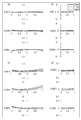
- Data 20 (correction optical system eccentricity ds (mm) data) Camera body rotation angle ⁇ c (°) 0 15 30 45 60 75 90 105 Wide to medium 0.00 0.00 0.00 0.00 0.00 0.00 0.00 Medium to telephoto 0.00 -2.59 -5.00 -7.07 -8.66 -9.66 -10.00 -9.66
- Data 21 (other data) Difference Dcd: 18 mm between the center of camera rotation and the center of curvature of the surface of the dome cover when shooting in the zenith direction Difference between the center of curvature of the surface of the dome cover and the center of curvature of the back surface when shooting in the zenith direction Dfr: 0.3 mm
- the dome camera of Numerical Example 4 corresponds to the fourth embodiment shown in FIG.
- the shape data of the dome cover is data 22
- the shape data of the correction optical system is data 23
- the focus position data at infinity of the lens system during horizontal shooting is data 24, and the correction optics
- the rotation angle data of the system is shown in data 25, and the other data is shown in data 26.
- Data 22 (Dome cover shape data) r d nd vd 1 80 d1 1.58 30 2 77 d2 When shooting in the zenith direction When shooting horizontally d1 2.0 3.0 d2 13.1819 38.1819
- Data 25 (correction optical system rotation angle ⁇ s (°) data)
- Data 26 (other data) Difference Dcd between camera rotation center and center of curvature of dome cover surface when shooting in zenith direction: 26mm Difference between the center of curvature of the surface of the dome cover and the center of curvature of the back surface when shooting in the zenith direction Dfr: 1.0 mm Distance of the correction optical system from surface 1 to the rotation center: 35.1274 mm
- the dome camera of Numerical Example 5 corresponds to Embodiment 5 shown in FIG.
- the shape data of the dome cover is data 27
- the shape data of the correction optical system is data 28
- the focus position data at infinity of the lens system during horizontal shooting is data 29, and the correction optics Data 30 shows the amount of eccentricity and rotation angle of the system, and data 31 shows the other data.
- Data 27 (Dome cover shape data) ry rx d nd vd 1 80 80 d1 1.58 30 2 77 77 d2 When shooting in the zenith direction When shooting horizontally d1 2.0 3.0 d2 13.1819 38.1819
- Data 31 (Other data) Difference Dcd between camera rotation center and center of curvature of dome cover surface when shooting in zenith direction: 26mm Difference between the center of curvature of the surface of the dome cover and the center of curvature of the back surface when shooting in the zenith direction Dfr: 1.0 mm
- the dome camera of Numerical Example 6 corresponds to Embodiment 6 shown in FIG.
- Surface data of the lens system used in the dome camera of Numerical Example 6 is shown as data 32, aspherical data is shown as data 33, and various data is shown as data 34.
- Data 34 (various lens system data) Zoom ratio 27.56613 Wide angle Medium telephoto Focal length 4.5200 24.5001 124.5993 F number 1.63339 4.05517 5.33997 Angle of view 37.1333 7.3579 1.4557 Image height 3.2200 3.2200 3.2200 Total lens length 106.0073 106.0154 106.0046 BF 3.80749 3.81579 3.80494 d7 0.5000 19.2660 27.3725 d15 28.6029 9.8368 1.7304 d18 12.1039 6.7204 0.5000 d23 1.6000 4.5098 3.4567 d25 2.0000 4.4736 11.7471 D23 and d25 are focus position data at infinity when photographing in the zenith direction.
- the infinitely far focus position data of the lens system at the time of horizontal photographing is data 35
- the dome cover shape data is data 36
- the eccentricity data of the correction optical system is data 37.
- Other data are shown as data 38, respectively.
- Data 37 (Eccentricity ds (mm) data in a direction perpendicular to the optical axis of the correction optical system) Camera body rotation angle ⁇ c (°) 0 15 30 45 60 75 90 105 Wide angle 0.00 0.00 0.00 0.00 0.00 0.00 0.00 0.00 Intermediate 0.00 -0.04 -0.07 -0.10 -0.12 -0.13 -0.14 -0.13 Telephoto 0.00 -0.07 -0.13 -0.19 -0.23 -0.26 -0.27 -0.26 In the data 32, 14 to 15 are surface numbers of the correction optical system.
- Data 38 (other data) Difference Dcd between the center of camera rotation and the center of curvature of the surface of the dome cover when shooting in the zenith direction: 20 mm Difference between the center of curvature of the surface of the dome cover and the center of curvature of the back surface when shooting in the zenith direction Dfr: 0.6 mm
- the lens system infinite focus position data at the time of horizontal shooting is data 42
- the dome cover shape data is data 43
- the tilt angle data of the correction optical system is data 44.
- Other data are shown in data 45, respectively.
- Data 44 (correction optical system tilt angle ⁇ s (°) data) Camera body rotation angle ⁇ c (°) 0 15 30 45 60 75 90 105 Wide to medium 0.00 0.00 0.00 0.00 0.00 0.00 0.00 Telephoto 0.00 -0.11 -0.22 -0.31 -0.38 -0.43 -0.44 -0.43
- reference numerals 17 to 18 are surface numbers of the correction optical system, and the center of rotation is the top of the object side surface (surface 17).
- Data 45 (other data) Difference Dcd between the center of camera rotation and the center of curvature of the surface of the dome cover when shooting in the zenith direction: 20 mm Difference between the center of curvature of the surface of the dome cover and the center of curvature of the back surface when shooting in the zenith direction Dfr: 0.6 mm Table 1 below shows corresponding values for each condition in the dome camera of each numerical example.
- This disclosure can be applied to, for example, surveillance cameras and security cameras.
Landscapes
- Physics & Mathematics (AREA)
- General Physics & Mathematics (AREA)
- Optics & Photonics (AREA)
- Engineering & Computer Science (AREA)
- Multimedia (AREA)
- Signal Processing (AREA)
- Nonlinear Science (AREA)
- Lenses (AREA)
- Studio Devices (AREA)
- Accessories Of Cameras (AREA)
Abstract
回動可能であって、レンズ系と撮像素子とを有するカメラ本体と、曲面形状を有する補正光学系と、カメラ本体及び補正光学系を覆うドームカバーとを備え、補正光学系は、カメラ本体の回動角に応じて、チルト、偏心及び回動の少なくとも1つを行う、ドームカメラ。
Description
本開示は、ドームカメラに関する。
特許文献1は、ドームカバーと、カメラ本体とを有する監視カメラ装置を開示している。監視カメラ装置は、2以上に分割された球形の一部分の形状のドームカバーと、被写体を撮影するカメラ本体と、カメラ本体を回動させるチルト機構とを備える。これにより、水平面よりも上方の被写体を撮影することができる。
本開示におけるドームカメラは、回動可能であって、レンズ系と撮像素子とを有するカメラ本体と、曲面形状を有する補正光学系と、前記カメラ本体及び前記補正光学系を覆うドームカバーと、を備え、前記補正光学系は、前記カメラ本体の回動角に応じて、チルト、偏心及び回動の少なくとも1つを行う。
以下、適宜図面を参照しながら、実施の形態を詳細に説明する。ただし、必要以上に詳細な説明は省略する場合がある。例えば、既によく知られた事項の詳細説明や実質的に同一の構成に対する重複説明を省略する場合がある。これは、以下の説明が不必要に冗長になるのを避け、当業者の理解を容易にするためである。
なお、発明者は、当業者が本開示を充分に理解するために添付図面および以下の説明を提供するのであって、これらによって特許請求の範囲に記載の主題を限定することを意図するものではない。
本開示において、補正光学系がチルト、偏心及び回動の少なくとも1つを行うことを、補正光学系が移動する、ともいう。また、補正光学系のチルト量、チルト角、回動角、偏心量等を、補正光学系の移動量、ともいう。
(実施の形態1)
以下、実施の形態1のドームカメラについて、図面を用いて説明する。実施の形態1では、監視カメラ等に用いられるドームカメラの場合を例示する。
以下、実施の形態1のドームカメラについて、図面を用いて説明する。実施の形態1では、監視カメラ等に用いられるドームカメラの場合を例示する。
[1-1.構成]
[1-1-1.全体構成]
図1A~図1Dを用いて実施の形態1に係るドームカメラ1の全体構成を説明する。実施の形態1に係るドームカメラ1は、カメラ本体200と、ドームカバー10と、可動式の補正光学系310とを備える。
[1-1-1.全体構成]
図1A~図1Dを用いて実施の形態1に係るドームカメラ1の全体構成を説明する。実施の形態1に係るドームカメラ1は、カメラ本体200と、ドームカバー10と、可動式の補正光学系310とを備える。
ドームカバー10の内部にあるカメラ本体200は、その内部にレンズ系と撮像素子とを有する。実施の形態1に係るドームカメラ1において、レンズ系はズームレンズ系である。
ドームカバー10は、全体形状がカップ形状をしており、略半球状の球面部10aと、円柱形状の円筒部10bとから構成される。球面部10aと円筒部10bとは、一体で成型されるが、それぞれ別体で成型した後に接合してもよい。また、円筒部10bは、円柱形状に限られず、円錐形状であってもよい。
補正光学系310は、ドームカバー10の円筒部10bを通過する光線を光学的に補正するためのものである。補正光学系310は、退避状態と、補正状態との間を移動可能に構成されている。退避状態は、補正光学系310が、カメラ本体200の回動角θcに応じて、カメラ本体200のレンズ系に入射する光線にかからない位置に移動した状態である。補正状態は、補正光学系310が、ドームカバー10とカメラ本体200との間の位置に移動した状態である。補正光学系310の動作の詳細は後述する。
ドームカメラ1は、パンモータ(図示せず)とチルトモータ(図示せず)とを備えている。カメラ本体200は、パンモータとチルトモータとにより、ドームカバー10に対して、パン方向とチルト方向とに回動可能である。パンモータ及びチルトモータは、マイコン等の制御部によって動作が制御されている。
ドームカメラ1は、補正光学系310を駆動させる補正光学系用アクチュエータ(図示せず)を備えている。補正光学系用アクチュエータは、マイコン等の制御部によって動作が制御されている。
[1-1-2.レンズ系の構成]
実施の形態1におけるカメラ本体200のレンズ系について説明する。図2は、実施の形態1におけるレンズ系の配置図であり、無限遠合焦状態にあるレンズ系を表している。なお、図2のレンズ系は、実施の形態2~5におけるカメラ本体200にも用いられている。
実施の形態1におけるカメラ本体200のレンズ系について説明する。図2は、実施の形態1におけるレンズ系の配置図であり、無限遠合焦状態にあるレンズ系を表している。なお、図2のレンズ系は、実施の形態2~5におけるカメラ本体200にも用いられている。
図2において、図2の(a)は広角端、(b)は中間位置、(c)は望遠端のレンズ構成をそれぞれ表している。図2の(a)の広角端とは、最短焦点距離状態をいう。最短焦点距離状態における焦点距離はfWである。図2の(b)の中間位置とは、中間焦点距離状態をいう。中間焦点距離状態における焦点距離fMは、以下の式で規定される。

図2の(c)の望遠端とは、最長焦点距離状態をいう。最長焦点距離状態における焦点距離はfTである。また各配置図において、図2の(a)と(b)との間に設けられた折れ線の矢印は、上から順に、広角端、中間位置、望遠端の各状態におけるレンズ群の位置を結んで得られる直線である。広角端と中間位置との間、中間位置と望遠端との間は、単純に直線で接続されているだけであり、実際の各レンズ群の動きとは異なる。
レンズ群に付された矢印は、無限遠合焦状態から近接物体合焦状態へのフォーカシングを表す。すなわち、図2では、後述する第5レンズ群G5が無限遠合焦状態から近接物体合焦状態へのフォーカシングの際に移動する方向を示している。なお、図2の(a)に各レンズ群の符号が記載されているため、便宜上、第5レンズ群G5の符号の下部にフォーカシングを表す矢印を付しているが、各ズーミング状態において、フォーカシングの際に第5レンズ群G5が移動する方向は、後に具体的に説明する。
レンズ系は、物体側から像側へと順に、正のパワーを有する第1レンズ群G1と、負のパワーを有する第2レンズ群G2と、開口絞りを有し、正のパワーを有する第3レンズ群G3と、正のパワーを有する第4レンズ群G4と、負のパワーを有する第5レンズ群G5と、正のパワーを有する第6レンズ群G6とを備える。
レンズ系は、広角端から望遠端へのズーミングに際して、各レンズ群の間隔、すなわち、第1レンズ群G1と第2レンズ群G2との間隔、第2レンズ群G2と第3レンズ群G3との間隔、第3レンズ群G3と第4レンズ群G4との間隔、第4レンズ群G4と第5レンズ群G5との間隔、及び第5レンズ群G5と第6レンズ群G6との間隔がいずれも変化するように、各レンズ群が光軸に沿った方向にそれぞれ移動する。
図2において、特定の面に付されたアスタリスク*は、特定の面が非球面であることを示している。各レンズ群の符号に付された記号(+)及び記号(-)は、各レンズ群のパワーの符号に対応する。最も右側に記載された直線は、像面Sの位置を表す。
図2に示すように、レンズ系において、第1レンズ群G1は、物体側から像側へと順に、物体側に凸面を向けた負メニスカス形状の第1レンズ素子L1と、物体側に凸面を向けた正メニスカス形状の第2レンズ素子L2と、物体側に凸面を向けた正メニスカス形状の第3レンズ素子L3と、物体側に凸面を向けた正メニスカス形状の第4レンズ素子L4とからなる。これらのうち、第1レンズ素子L1と第2レンズ素子L2とは接合されている。
第2レンズ群G2は、物体側から像側へと順に、物体側に凸面を向けた負メニスカス形状の第5レンズ素子L5と、両凹形状の第6レンズ素子L6と、両凸形状の第7レンズ素子L7と、両凹形状の第8レンズ素子L8とからなる。第6レンズ素子L6の物体側面及び像側面は非球面である。
第3レンズ群G3は、物体側から像側へと順に、開口絞りAと、物体側に凸面を向けた正メニスカス形状の第9レンズ素子L9とからなる。第9レンズ素子L9の像側面は非球面である。
第4レンズ群G4は、物体側から像側へと順に、両凸形状の第10レンズ素子L10と、両凸形状の第11レンズ素子L11と、像側に凸面を向けた負メニスカス形状の第12レンズ素子L12とからなる。これらのうち、第11レンズ素子L11と第12レンズ素子L12とは接合されている。第10レンズ素子L10の物体側面及び像側面は非球面である。
第5レンズ群G5は、両凹形状の第13レンズ素子L13のみからなる。
第6レンズ群G6は、両凸形状の第14レンズ素子L14のみからなる。
撮像時の広角端から望遠端へのズーミングの際に、第1レンズ群G1、開口絞りAと第3レンズ群G3、及び第6レンズ群G6は、移動せず、第2レンズ群G2は、単調に像側へ移動し、第4レンズ群G4及び第5レンズ群G5は、物体側へ移動する。すなわち、ズーミングに際して、第1レンズ群G1と第2レンズ群G2との間隔、及び第5レンズ群G5と第6レンズ群G6との間隔が増大し、第2レンズ群G2と第3レンズ群G3との間隔、及び第3レンズ群G3と第4レンズ群G4との間隔が減少し、第4レンズ群G4と第5レンズ群G5との間隔が変化するように、各レンズ群が光軸に沿ってそれぞれ移動する。
無限遠合焦状態から近接物体合焦状態へのフォーカシングの際に、フォーカシングレンズ群である第5レンズ群G5は、いずれのズーミング状態でも光軸に沿って像側へ移動する。
[1-1-3.補正光学系の構成]
図3A及び図3Bは、実施の形態1における補正光学系310の説明図である。図3Aは、補正光学系310の斜視図であり、図3Bは、補正光学系310をY軸及びZ軸垂直方向から見た図である。実施の形態1における補正光学系310は、シリンドリカル形状の1枚の光学素子で構成されている。具体的には、補正光学系310は、そのY軸方向(頂点方向)にのみ曲率を有しており、X軸方向(頂点方向に対して垂直方向)の曲率は無限大である。すなわち、補正光学系310は、X軸方向とY軸方向とで曲率が異なる形状を有している。また、補正光学系310は、カメラ本体200において被写体側に相当する側の面と像面側に相当する側の面とが、図3Bで示すY軸方向に偏心している。
図3A及び図3Bは、実施の形態1における補正光学系310の説明図である。図3Aは、補正光学系310の斜視図であり、図3Bは、補正光学系310をY軸及びZ軸垂直方向から見た図である。実施の形態1における補正光学系310は、シリンドリカル形状の1枚の光学素子で構成されている。具体的には、補正光学系310は、そのY軸方向(頂点方向)にのみ曲率を有しており、X軸方向(頂点方向に対して垂直方向)の曲率は無限大である。すなわち、補正光学系310は、X軸方向とY軸方向とで曲率が異なる形状を有している。また、補正光学系310は、カメラ本体200において被写体側に相当する側の面と像面側に相当する側の面とが、図3Bで示すY軸方向に偏心している。
実施の形態1に係る補正光学系310は、そのドームカバー側の面のドーム天頂側(Y軸方向)の端部に、遮光部311を備えている。遮光部311は、印刷で設けることも可能であるが、実施の形態1では、補正光学系310の光学素子を保持する枠を遮光部311としている。
[1-2.動作]
図1は、実施の形態1に係るドームカメラ1の概略断面を示す図で、カメラ本体200と補正光学系310との動作の関係を示す説明図ある。図1Aは、ドームカバー10の天頂方向撮影時を示している。図1Bは、図1Aの天頂方向撮影状態に対してカメラ本体200がθcだけ回動している斜め撮影時を示している。図1Cは、ドームカバー10の天頂方向に対して垂直方向である水平撮影時を示している。図1Dは、図1Cの水平撮影状態に対して天頂方向とは逆方向にカメラ本体200がθcだけ回動している逆天頂方向斜め撮影時を示している。カメラ本体200は、カメラ本体200の回動中心3を中心軸にして回動する。カメラ本体200の回動中心3は、ドームカバー10の球心位置(球面部10aの曲率中心2)よりもドームカバー10の天頂方向に位置している。
図1は、実施の形態1に係るドームカメラ1の概略断面を示す図で、カメラ本体200と補正光学系310との動作の関係を示す説明図ある。図1Aは、ドームカバー10の天頂方向撮影時を示している。図1Bは、図1Aの天頂方向撮影状態に対してカメラ本体200がθcだけ回動している斜め撮影時を示している。図1Cは、ドームカバー10の天頂方向に対して垂直方向である水平撮影時を示している。図1Dは、図1Cの水平撮影状態に対して天頂方向とは逆方向にカメラ本体200がθcだけ回動している逆天頂方向斜め撮影時を示している。カメラ本体200は、カメラ本体200の回動中心3を中心軸にして回動する。カメラ本体200の回動中心3は、ドームカバー10の球心位置(球面部10aの曲率中心2)よりもドームカバー10の天頂方向に位置している。
次に、図1A~図1Dを用いて、実施の形態1に係るドームカメラ1の動作を説明する。
レンズ系のズーミング位置が広角端から中間位置の領域では、カメラ本体200の回動角θcに関わらず、補正光学系310は、カメラ本体200の撮影範囲外に退避している。一方、レンズ系のズーミング位置が中間位置から望遠端の領域では、補正光学系310は、カメラ本体200の回動角θcに応じて、カメラ本体200の撮影範囲内に挿入される。
具体的には、カメラ本体200の回動角θcが0~85°のときには、補正光学系310はカメラ本体200の撮影範囲外に退避する。カメラ本体200の光線が、円筒部10bを通過する角度、すなわち、カメラ本体200の回動角θcが85°を超えると、補正光学系310はカメラ本体200の撮影範囲内に挿入される。
図1Cに示すように、カメラ本体200の回動角θcが90°のときは、カメラ本体200の光軸Oと、ドームカバー10の円筒部10b及び球面部10aの境界と補正光学系310の天頂側の端部とを結ぶ線とが平行になる。θcが90°のときの補正光学系310の位置を0としたとき、θcが90°よりも大きくなると、補正光学系310は、ドームカバー10の天頂方向へ円筒部10bに対して平行に偏心する。θcが90°よりも小さくなると、補正光学系310は、ドームカバー10の天頂方向とは逆方向へ偏心し、カメラ本体200の光軸Oと、ドームカバー10の円筒部10b及び球面部10aの境界と補正光学系310の天頂側の端部とを結ぶ線とが平行になるように偏心する。つまり、θcの変化に合わせて、光軸Oと、ドームカバー10の円筒部10b及び球面部10aの境界と補正光学系310の天頂側の端部とを結ぶ線とが平行になるように、補正光学系310は偏心する。なお、図1中、補正光学系310が偏心する際の偏心量をdsで表している。
[1-3.効果等]
実施の形態1に係るドームカメラ1によれば、カメラ本体200がドームカバー10の円筒部10b方向の被写体を撮影する場合でも、偏心コマ収差、片ボケ、非点収差等が改善され、高品位な画像を撮影することが可能である。
実施の形態1に係るドームカメラ1によれば、カメラ本体200がドームカバー10の円筒部10b方向の被写体を撮影する場合でも、偏心コマ収差、片ボケ、非点収差等が改善され、高品位な画像を撮影することが可能である。
図4の(a)、(b)、(c)、(d)を参照して、実施の形態1に係るドームカメラ1の効果を説明する。図4の(a)、(b)は、補正光学系310で補正した場合の水平撮影時(θc=90°)の望遠端での横収差図で、図4の(c)、(d)は、補正光学系310で補正していない場合の水平撮影時(θc=90°)の望遠端での横収差図である。図4の(a)、(c)は、メリジオナル方向の横収差図で、図4の(b)、(d)は、サジタル方向の横収差図であり、実線はd線(d-line)、短破線はF線(F-line)、長破線はC線(C-line)の特性である。図4の(c)において、-0.50FAと0.00FAの瞳1.0側に像面の倒れが認められるが、図4の(a)においては、像面の倒れが改善されていることがわかる。
ドームカバー10の円筒部10bは、X軸方向(頂点方向に対して垂直方向)とY軸方向(頂点方向)とで曲率が異なる。そこで、補正光学系310により、X軸方向の曲率とY軸方向の曲率との差異を補正して、円筒部10bを通過するX軸方向とY軸方向の結像位置を同じにし、円筒部10bを通過する光線のメリジオナル方向での像面の倒れを補正している。なお、図4の(a)、(b)、(c)、(d)横収差図の瞳は、各画角における上光線の位置を1、下光線の位置を-1、主光線の位置を0としている。
(実施の形態2)
図5A~図5D及び図6A、図6Bを用いて実施の形態2に係るドームカメラを説明する。実施の形態2では、実施の形態1と同様の構成においては同じ符号を付し、異なる構成を中心に説明する。
図5A~図5D及び図6A、図6Bを用いて実施の形態2に係るドームカメラを説明する。実施の形態2では、実施の形態1と同様の構成においては同じ符号を付し、異なる構成を中心に説明する。
[2-1-1.全体構成]
図5A~図5Dは、実施の形態2に係るドームカメラ1の概略断面を示す図で、カメラ本体200と補正光学系320との動作の関係を示す説明図ある。実施の形態2では、補正光学系320の形状が実施の形態1と異なり、カメラ本体200内部のレンズ系やドームカバー10の形状は実施の形態1と同じである。
図5A~図5Dは、実施の形態2に係るドームカメラ1の概略断面を示す図で、カメラ本体200と補正光学系320との動作の関係を示す説明図ある。実施の形態2では、補正光学系320の形状が実施の形態1と異なり、カメラ本体200内部のレンズ系やドームカバー10の形状は実施の形態1と同じである。
[2-1-2.補正光学系の構成]
図6A及び図6Bは、実施の形態2における補正光学系320の説明図である。図6Aは、補正光学系320の斜視図であり、図6Bは、補正光学系320をY軸及びZ軸垂直方向から見た図である。実施の形態2における補正光学系320は、曲面部320aと平面部320bとからなる1枚の光学素子で構成されている。曲面部320aは、実施の形態1と同様にシリンドリカル形状である。曲面部320aは、そのY軸方向(頂点方向)にのみ曲率を有しており、X軸方向(頂点方向に対して垂直方向)の曲率は無限大である。すなわち、曲面部320aは、X軸方向とY軸方向とで曲率が異なる形状を有している。また、曲面部320aは、カメラ本体200において被写体側に相当する側の面と像面側に相当する側の面とが、図6Bで示すY軸方向に偏心している。平面部320bは、そのX軸方向、Y軸方向ともに、曲率は無限大である。すなわち、平面部320bは平板状である。
図6A及び図6Bは、実施の形態2における補正光学系320の説明図である。図6Aは、補正光学系320の斜視図であり、図6Bは、補正光学系320をY軸及びZ軸垂直方向から見た図である。実施の形態2における補正光学系320は、曲面部320aと平面部320bとからなる1枚の光学素子で構成されている。曲面部320aは、実施の形態1と同様にシリンドリカル形状である。曲面部320aは、そのY軸方向(頂点方向)にのみ曲率を有しており、X軸方向(頂点方向に対して垂直方向)の曲率は無限大である。すなわち、曲面部320aは、X軸方向とY軸方向とで曲率が異なる形状を有している。また、曲面部320aは、カメラ本体200において被写体側に相当する側の面と像面側に相当する側の面とが、図6Bで示すY軸方向に偏心している。平面部320bは、そのX軸方向、Y軸方向ともに、曲率は無限大である。すなわち、平面部320bは平板状である。
[2-2.動作]
図5Aは、ドームカバー10の天頂方向撮影時を示している。図5Bは、図5Aの天頂方向撮影状態に対してカメラ本体200がθcだけ回動している斜め撮影時を示している。図5Cは、ドームカバー10の天頂方向に対して垂直方向である水平撮影時を示している。図5Dは、図5Cの水平撮影状態に対して天頂方向とは逆方向にカメラ本体200がθcだけ回動している逆天頂方向斜め撮影時を示している。カメラ本体200は、カメラ本体200の回動中心3を中心軸にして回動する。カメラ本体200の回動中心3は、ドームカバー10の球心位置(球面部10aの曲率中心2)よりもドームカバー10の天頂方向に位置している。
図5Aは、ドームカバー10の天頂方向撮影時を示している。図5Bは、図5Aの天頂方向撮影状態に対してカメラ本体200がθcだけ回動している斜め撮影時を示している。図5Cは、ドームカバー10の天頂方向に対して垂直方向である水平撮影時を示している。図5Dは、図5Cの水平撮影状態に対して天頂方向とは逆方向にカメラ本体200がθcだけ回動している逆天頂方向斜め撮影時を示している。カメラ本体200は、カメラ本体200の回動中心3を中心軸にして回動する。カメラ本体200の回動中心3は、ドームカバー10の球心位置(球面部10aの曲率中心2)よりもドームカバー10の天頂方向に位置している。
次に、図5A~図5Dを用いて、実施の形態2に係るドームカメラ1の動作を説明する。
レンズ系のズーミング位置が広角端から中間位置の領域では、カメラ本体200の回動角θcに関わらず、補正光学系320は、カメラ本体200の撮影範囲外に退避している。一方、レンズ系のズーミング位置が中間位置から望遠端の領域では、補正光学系320は、カメラ本体200の回動角θcに応じて、補正光学系回動中心4を軸に回動角θsだけ回動して、カメラ本体200の撮影範囲内に挿入される。
具体的には、カメラ本体200の回動角θcが0~85°のときには、補正光学系320はカメラ本体200の撮影範囲外に退避する。図5A、図5Bに示すように、実施の形態2において、補正光学系320はカメラ本体200の側方に沿うように退避している。カメラ本体200の画角内に円筒部10bが入る角度、すなわち、カメラ本体200の回動角θcが85°を超えると、補正光学系320はカメラ本体200の撮影範囲内に挿入される。
図5Cに示すように、カメラ本体200の回動角θcが90°のときは、カメラ本体200の光軸Oと、ドームカバー10の円筒部10b及び球面部10aの境界と補正光学系320の曲面部320a及び平面部320bの境界とを結ぶ線とが平行になる。θcが90°のときの補正光学系320の位置を0としたとき、θcが90°よりも大きくなると、補正光学系320は、ドームカバー10の天頂方向へ回動する。θcが90°よりも小さくなると、補正光学系320は、ドームカバー10の天頂方向とは逆方向へ回動する。ここで、補正光学系320における回動とは、補正光学系回動中心4が補正光学系320とは別の位置にある場合をいう。その際、カメラ本体200の光軸Oと、ドームカバー10の円筒部10b及び球面部10aの境界と補正光学系320の曲面部320a及び平面部320bの境界とを結ぶ線とが平行になるように、補正光学系320は回動する。つまり、θcの変化に合わせて、光軸Oと、ドームカバー10の円筒部10b及び球面部10aの境界と補正光学系320の曲面部320a及び平面部320bの境界とを結ぶ線とが平行になるように、補正光学系320は回動する。
[2-3.効果等]
実施の形態2に係るドームカメラ1によれば、カメラ本体200がドームカバー10の円筒部10b方向の被写体を撮影する場合でも、偏心コマ収差や非点収差の発生が抑制され、かつ、光量減少が小さい高品位な画像を撮影することが可能である。
実施の形態2に係るドームカメラ1によれば、カメラ本体200がドームカバー10の円筒部10b方向の被写体を撮影する場合でも、偏心コマ収差や非点収差の発生が抑制され、かつ、光量減少が小さい高品位な画像を撮影することが可能である。
図7の(a)、(b)、(c)、(d)を参照して、実施の形態2に係るドームカメラ1の効果を説明する。図7の(a)、(b)は、補正光学系320で補正した場合の水平撮影時(θc=90°)の望遠端での横収差図で、図7の(c)、(d)は、補正光学系320で補正していない場合の水平撮影時(θc=90°)の望遠端での横収差図である。図7の(a)、(c)は、メリジオナル方向の横収差図で、図7の(b)、(d)は、サジタル方向の横収差図であり、実線はd線(d-line)、短破線はF線(F-line)、長破線はC線(C-line)の特性である。図7の(c)において、-0.50FAと0.00FAの瞳1.0側に像面の倒れが認められるが、図7の(a)においては、像面の倒れが改善されていることがわかる。
ドームカバー10の円筒部10bは、X軸方向(頂点方向に対して垂直方向)とY軸方向(頂点方向)とで曲率が異なる。そこで、補正光学系320により、X軸方向の曲率とY軸方向の曲率との差異を補正して、円筒部10bを通過するX軸方向とY軸方向の結像位置を同じにし、円筒部10bを通過する光線のメリジオナル方向での像面の倒れを補正している。なお、図7の(a)の-0.50FAの瞳0.4のメリジオナル方向の横収差が飛び出ているのは、補正光学系320の曲面部320aと平面部320bとの境界付近のゴーストによるものである。このようなゴーストの発生は、補正光学系320に遮光部321を設けることによって抑制することができる。実施の形態2において、遮光部321は、補正光学系320のドームカバー側の面に設けられている。
(実施の形態3)
[3-1.構成]
図8A~図8Dは、実施の形態3に係るドームカメラ1の概略断面を示す図で、カメラ本体200と補正光学系330との動作の関係を示す説明図ある。実施の形態3に係るドームカメラ1は、カメラ本体200と、ドームカバー10と、補正光学系330とを備えている。補正光学系330は偏心補正光学系であり、1枚の光学素子で構成されている。
[3-1.構成]
図8A~図8Dは、実施の形態3に係るドームカメラ1の概略断面を示す図で、カメラ本体200と補正光学系330との動作の関係を示す説明図ある。実施の形態3に係るドームカメラ1は、カメラ本体200と、ドームカバー10と、補正光学系330とを備えている。補正光学系330は偏心補正光学系であり、1枚の光学素子で構成されている。
ドームカバー10の内部にあるカメラ本体200は、その内部にレンズ系と撮像素子とを有する。レンズ系の構成は実施の形態1と同じであり、レンズ系はズームレンズ系である。
ドームカバー10は略半球状であり、ドームカバーの外側(表面)の曲率半径と内側(裏面)の曲率半径とが異なる。なお、ドームカバー10は、表面側及び裏面側で球面を有するが、ドームカバー10の厚みは、ドームカバー10の天頂部分が最も小さく、天頂部分から遠ざかるに従って大きいことが有益である。これは、カメラ本体200が傾くと、ドームカバー10の曲率中心2とカメラ本体200の回動中心3とが離れているので、ドームカバー10と光軸Oとのずれによって収差が発生するが、この収差を補正することができるからである。
補正光学系330は、ドームカバー10を通過する光線を光学的に補正する。補正光学系330は、カメラ本体200の回動角θcに応じて、光軸に対して垂直に偏心(ディセンター)する。後に、補正光学系330の動作について詳細に説明する。実施の形態3における補正光学系330は、正のパワーを有し、メニスカス形状である。
[3-2.動作]
図8Aは、ドームカバー10の天頂方向撮影時を示している。図8Bは、図8Aの天頂方向撮影状態に対してカメラ本体200がθcだけ回動している斜め撮影時を示している。図8Cは、ドームカバー10の天頂方向に対して垂直方向である水平撮影時を示している。図8Dは、図8Cの水平撮影状態に対して天頂方向とは逆方向にカメラ本体200がθcだけ回動している逆天頂方向斜め撮影時を示している。カメラ本体200は、カメラ本体200の回動中心3を中心軸にして回動する。カメラ本体200の回動中心3は、ドームカバー10の球心位置(曲率中心2)よりもドームカバー10の天頂方向に位置している。
図8Aは、ドームカバー10の天頂方向撮影時を示している。図8Bは、図8Aの天頂方向撮影状態に対してカメラ本体200がθcだけ回動している斜め撮影時を示している。図8Cは、ドームカバー10の天頂方向に対して垂直方向である水平撮影時を示している。図8Dは、図8Cの水平撮影状態に対して天頂方向とは逆方向にカメラ本体200がθcだけ回動している逆天頂方向斜め撮影時を示している。カメラ本体200は、カメラ本体200の回動中心3を中心軸にして回動する。カメラ本体200の回動中心3は、ドームカバー10の球心位置(曲率中心2)よりもドームカバー10の天頂方向に位置している。
次に、図8A~図8Dを用いて、実施の形態3に係るドームカメラ1の動作を説明する。
レンズ系のズーミング位置が広角端から中間位置の領域では、図8Aに示すように、カメラ本体200の光軸Oは、補正光学系330の中心を通る。すなわち、補正光学系330は偏心しない。
レンズ系のズーミング位置が中間位置から望遠端の領域では、次のとおりである。図8Aに示すように、カメラ本体200がドームカバー10の天頂方向を撮影している状態では、補正光学系330の中心は光軸O上に位置する。カメラ本体200が図8Aに示す状態から水平方向に傾くにしたがって、補正光学系330は、光軸Oに対して垂直にドームカバー10の天頂方向とは逆方向に偏心する。カメラ本体200の回動角θcが90°の状態において、補正光学系330の偏心量dsの絶対値が最も大きくなる。図8Dに示すように、θcが90°を超えた状態の場合、補正光学系330の偏心量dsの絶対値は減少する。
[3-3.効果等]
実施の形態3に係るドームカメラ1によれば、ドームカバー10とカメラ本体200の光軸Oとの偏心により発生する収差を良好に補正することができる。
実施の形態3に係るドームカメラ1によれば、ドームカバー10とカメラ本体200の光軸Oとの偏心により発生する収差を良好に補正することができる。
図9の(a)、(b)、(c)、(d)を参照して、実施の形態3に係るドームカメラ1の効果を説明する。図9の(a)、(b)は、補正光学系330で補正した場合の水平撮影時(θc=90°)の望遠端での横収差図で、図9の(c)、(d)は、補正光学系330で補正していない場合の水平撮影時(θc=90°)の望遠端での横収差図である。図9の(a)、(c)は、メリジオナル方向の横収差図で、図9の(b)、(d)は、サジタル方向の横収差図であり、実線はd線(d-line)、短破線はF線(F-line)、長破線はC線(C-line)の特性である。図9の(c)、(d)で認められている各収差が、図9の(a)、(b)では改善されており、補正光学系330を偏心させることによって、特にコマ収差が改善されていることがわかる。
(実施の形態4)
[4-1.構成]
図10A~図10Dは、実施の形態4に係るドームカメラ1の概略断面を示す図で、カメラ本体200と補正光学系340との動作の関係を示す説明図ある。実施の形態4に係るドームカメラ1は、カメラ本体200と、ドームカバー10と、補正光学系340とを備えている。補正光学系340は、可動式補正光学系340aと、可動式補正光学系340aのカメラ本体200側の隣に、固定式補正光学系340bとを備える。
[4-1.構成]
図10A~図10Dは、実施の形態4に係るドームカメラ1の概略断面を示す図で、カメラ本体200と補正光学系340との動作の関係を示す説明図ある。実施の形態4に係るドームカメラ1は、カメラ本体200と、ドームカバー10と、補正光学系340とを備えている。補正光学系340は、可動式補正光学系340aと、可動式補正光学系340aのカメラ本体200側の隣に、固定式補正光学系340bとを備える。
ドームカバー10の内部にあるカメラ本体200は、その内部にレンズ系と撮像素子とを有する。レンズ系の構成は実施の形態1と同じであり、レンズ系はズームレンズ系である。ドームカバー10は略半球状である。
可動式補正光学系340aは、カメラ本体200の回動角θcに応じて、補正光学系回動中心4を軸に回動する。後に、可動式補正光学系340aの動作について詳細に説明する。実施の形態4における可動式補正光学系340aは、負のパワーを有し、メニスカス形状である。固定式補正光学系340bは、正のパワーを有し、メニスカス形状である。
[4-2.動作]
図10Aは、ドームカバー10の天頂方向撮影時を示している。図10Bは、図10Aの天頂方向撮影状態に対してカメラ本体200がθcだけ回動している斜め撮影時を示している。図10Cは、ドームカバー10の天頂方向に対して垂直方向である水平撮影時を示している。図10Dは、図10Cの水平撮影状態に対して天頂方向とは逆の方向にカメラ本体200がθcだけ回動している逆天頂方向斜め撮影時を示している。カメラ本体200は、カメラ本体200の回動中心3を中心軸にして回動する。カメラ本体200の回動中心3は、ドームカバー10の球心位置(曲率中心2)よりもドームカバー10の天頂方向に位置している。
図10Aは、ドームカバー10の天頂方向撮影時を示している。図10Bは、図10Aの天頂方向撮影状態に対してカメラ本体200がθcだけ回動している斜め撮影時を示している。図10Cは、ドームカバー10の天頂方向に対して垂直方向である水平撮影時を示している。図10Dは、図10Cの水平撮影状態に対して天頂方向とは逆の方向にカメラ本体200がθcだけ回動している逆天頂方向斜め撮影時を示している。カメラ本体200は、カメラ本体200の回動中心3を中心軸にして回動する。カメラ本体200の回動中心3は、ドームカバー10の球心位置(曲率中心2)よりもドームカバー10の天頂方向に位置している。
次に、図10A~図10Dを用いて、実施の形態4に係るドームカメラ1の動作を説明する。
レンズ系のズーミング位置が広角端から中間位置の領域では、図10Aに示すように、補正光学系回動中心4は、カメラ本体200の光軸Oを通る。
レンズ系のズーミング位置が中間位置から望遠端の領域では、次のとおりである。図10Aに示すように、カメラ本体200がドームカバー10の天頂方向を撮影している状態では、補正光学系回動中心4は光軸O上に位置しており、可動式補正光学系340aは回動しない。カメラ本体200が図10Aに示す状態から水平方向に傾くにしたがって、可動式補正光学系340aは、補正光学系回動中心4を中心に天頂方向とは逆方向に回動する。可動式補正光学系340aの回動角θsは、カメラ本体200の撮影方向が天頂方向であるときに0°である。カメラ本体200の回動角θcが大きくなるにしたがって、可動式補正光学系340aの回動角θsも増大する。θcが90°のときに、θsが最も大きくなる。図10Dに示すように、θcが90°を超えた場合、θsは減少する。
[4-3.効果等]
実施の形態4に係るドームカメラ1によれば、ドームカバー10とカメラ本体200の光軸Oとの偏心により発生する収差を良好に補正することができる。
実施の形態4に係るドームカメラ1によれば、ドームカバー10とカメラ本体200の光軸Oとの偏心により発生する収差を良好に補正することができる。
図11の(a)、(b)、(c)、(d)を参照して、実施の形態4に係るドームカメラ1の効果を説明する。図11の(a)、(b)は、補正光学系340で補正した場合の水平撮影時(θc=90°)の望遠端での横収差図で、図11の(c)、(d)は、補正光学系340で補正していない場合の水平撮影時(θc=90°)の望遠端での横収差図である。図11の(a)、(c)は、メリジオナル方向の横収差図で、図11の(b)、(d)は、サジタル方向の横収差図であり、実線はd線(d-line)、短破線はF線(F-line)、長破線はC線(C-line)の特性である。図11の(c)、(d)で認められている各収差が、図11の(a)、(b)では改善されており、可動式補正光学系340aを回動させることによって、特にコマ収差及び色収差が改善されていることがわかる。
(実施の形態5)
[5-1.構成]
図12A~図12Dは、実施の形態5に係るドームカメラ1の概略断面を示す図で、カメラ本体200と補正光学系350との動作の関係を示す説明図ある。実施の形態5に係るドームカメラ1は、カメラ本体200と、ドームカバー10と、補正光学系350とを備えている。補正光学系350は、可動式補正光学系350aと、可動式補正光学系350aのカメラ本体200側の隣に、固定式補正光学系350bとを備える。
[5-1.構成]
図12A~図12Dは、実施の形態5に係るドームカメラ1の概略断面を示す図で、カメラ本体200と補正光学系350との動作の関係を示す説明図ある。実施の形態5に係るドームカメラ1は、カメラ本体200と、ドームカバー10と、補正光学系350とを備えている。補正光学系350は、可動式補正光学系350aと、可動式補正光学系350aのカメラ本体200側の隣に、固定式補正光学系350bとを備える。
ドームカバー10の内部にあるカメラ本体200は、その内部にレンズ系と撮像素子とを有する。レンズ系の構成は実施の形態1と同じであり、レンズ系はズームレンズ系である。ドームカバー10は略半球状である。
可動式補正光学系350aは、カメラ本体200の回動角θcに応じて、補正光学系回動中心5を軸に回動し、かつ、偏心する。後に、可動式補正光学系350aの動作について詳細に説明する。実施の形態5における可動式補正光学系350aは、正のパワーを有し、メニスカス形状である。固定式補正光学系350bは、負のパワーを有し、メニスカス形状である。
[5-2.動作]
図12Aは、ドームカバー10の天頂方向撮影時を示している。図12Bは、図12Aの天頂方向撮影状態に対してカメラ本体200がθcだけ回動している斜め撮影時を示している。図12Cは、ドームカバー10の天頂方向に対して垂直方向である水平撮影時を示している。図12Dは、図12Cの水平撮影状態に対して天頂方向とは逆の方向にカメラ本体200がθcだけ回動している逆天頂方向斜め撮影時を示している。カメラ本体200は、カメラ本体200の回動中心3を中心軸にして回動する。カメラ本体200の回動中心3は、ドームカバー10の球心位置(曲率中心2)よりもドームカバー10の天頂方向に位置している。
図12Aは、ドームカバー10の天頂方向撮影時を示している。図12Bは、図12Aの天頂方向撮影状態に対してカメラ本体200がθcだけ回動している斜め撮影時を示している。図12Cは、ドームカバー10の天頂方向に対して垂直方向である水平撮影時を示している。図12Dは、図12Cの水平撮影状態に対して天頂方向とは逆の方向にカメラ本体200がθcだけ回動している逆天頂方向斜め撮影時を示している。カメラ本体200は、カメラ本体200の回動中心3を中心軸にして回動する。カメラ本体200の回動中心3は、ドームカバー10の球心位置(曲率中心2)よりもドームカバー10の天頂方向に位置している。
次に、図12A~図12Dを用いて、実施の形態5に係るドームカメラ1の動作を説明する。
レンズ系のズーミング位置が広角端から中間位置の領域では、カメラ本体200の回動角θcに関わらず、補正光学系回動中心5はカメラ本体200の光軸O上に位置する。すなわち、可動式補正光学系350aは、回動及び偏心しない。
レンズ系のズーミング位置が中間位置から望遠端の領域では、次のとおりである。図12Aに示すように、カメラ本体200がドームカバー10の天頂方向を撮影している状態では、補正光学系回動中心5は光軸O上に位置しており、可動式補正光学系350aは、回動及び偏心しない。カメラ本体200が図12Aに示す状態から水平方向に傾くと、すなわち、カメラ本体200の回動角θcが増大すると、可動式補正光学系350aは、補正光学系回動中心5を中心に回動角θsだけドームカバー10の天頂方向に回動し、偏心量dsだけ光軸O方向に対して垂直に天頂方向とは逆方向に偏心する。θcが90°のときに、θsが最も大きくなる。θcが90°のときを境に、回動角θsは減少する。一方dsは、θcの大きさに比例する。
[5-3.効果等]
実施の形態5に係るドームカメラ1によれば、ドームカバー10とカメラ本体200の光軸Oとの偏心により発生する収差を良好に補正することができる。
実施の形態5に係るドームカメラ1によれば、ドームカバー10とカメラ本体200の光軸Oとの偏心により発生する収差を良好に補正することができる。
図13の(a)、(b)、(c)、(d)を参照して、実施の形態5に係るドームカメラ1の効果を説明する。図13の(a)、(b)は、補正光学系350で補正した場合の水平撮影時(θc=90°)の望遠端での横収差図で、図13の(c)、(d)は、補正光学系350で補正していない場合の水平撮影時(θc=90°)の望遠端での横収差図である。図13の(a)、(c)は、メリジオナル方向の横収差図で、図13の(b)、(d)は、サジタル方向の横収差図であり、実線はd線(d-line)、短破線はF線(F-line)、長破線はC線(C-line)の特性である。図13の(c)、(d)で認められている各収差が、図13の(a)、(b)では改善されており、可動式補正光学系350aを回動及び偏心させることによって、特にコマ収差及び色収差が改善されていることがわかる。
(実施の形態6)
[6-1.構成]
[6-1-1.全体構成]
図14A~図14Dを用いて実施の形態6に係るドームカメラの全体構成を説明する。実施の形態6に係るドームカメラ1は、カメラ本体200と、ドームカバー10とを備える。
[6-1.構成]
[6-1-1.全体構成]
図14A~図14Dを用いて実施の形態6に係るドームカメラの全体構成を説明する。実施の形態6に係るドームカメラ1は、カメラ本体200と、ドームカバー10とを備える。
ドームカバー10の内部にあるカメラ本体200は、その内部にレンズ系と撮像素子とを有する。実施の形態6に係るドームカメラ1において、レンズ系はズームレンズ系であり、ドームカバー10は略半球状である。
ドームカメラ1は、パンモータ(図示せず)とチルトモータ(図示せず)とを備えている。カメラ本体200は、パンモータとチルトモータとにより、ドームカバー10に対して、パン方向とチルト方向とに回動可能である。パンモータ及びチルトモータは、マイコン等の制御部によって動作が制御されている。
[6-1-2.レンズ構成]
実施の形態6におけるカメラ本体200のレンズ系について説明する。図15は、実施の形態6に係るレンズ系の配置図であり、無限遠合焦状態にあるレンズ系を表している。
実施の形態6におけるカメラ本体200のレンズ系について説明する。図15は、実施の形態6に係るレンズ系の配置図であり、無限遠合焦状態にあるレンズ系を表している。
図15において、(a)は広角端、(b)は中間位置、(c)は望遠端のレンズ構成をそれぞれ表している。図15の(a)の広角端とは、最短焦点距離状態をいう。最短焦点距離状態における焦点距離はfWである。図15の(b)の中間位置とは、中間焦点距離状態をいう。中間焦点距離状態における焦点距離fMは、以下の式で規定される。
図15の(c)の望遠端とは、最長焦点距離状態をいう。最長焦点距離状態における焦点距離はfTである。また各配置図において、図15の(a)と(b)との間に設けられた折れ線の矢印は、上から順に、広角端、中間位置、望遠端の各状態におけるレンズ群の位置を結んで得られる直線である。広角端と中間位置との間、中間位置と望遠端との間は、単純に直線で接続されているだけであり、実際の各レンズ群の動きとは異なる。
レンズ群に付された矢印は、無限遠合焦状態から近接物体合焦状態へのフォーカシングを表す。すなわち、図15では、後述する第5レンズ群G5が無限遠合焦状態から近接物体合焦状態へのフォーカシングの際に移動する方向を示している。なお、図15の(a)に各レンズ群の符号が記載されているため、便宜上、第5レンズ群G5の符号の下部にフォーカシングを表す矢印を付しているが、各ズーミング状態において、フォーカシングの際に第5レンズ群G5が移動する方向は、後に具体的に説明する。
レンズ系は、物体側から像側へと順に、正のパワーを有する第1レンズ群G1と、負のパワーを有する第2レンズ群G2と、開口絞りを有し、正のパワーを有する第3レンズ群G3と、正のパワーを有する第4レンズ群G4と、負のパワーを有する第5レンズ群G5と、正のパワーを有する第6レンズ群G6とを備える。
レンズ系は、広角端から望遠端へのズーミングに際して、各レンズ群の間隔、すなわち、第1レンズ群G1と第2レンズ群G2との間隔、第2レンズ群G2と第3レンズ群G3との間隔、第3レンズ群G3と第4レンズ群G4との間隔、第4レンズ群G4と第5レンズ群G5との間隔、及び第5レンズ群G5と第6レンズ群G6との間隔がいずれも変化するように、各レンズ群が光軸に沿った方向にそれぞれ移動する。
図15において、特定の面に付されたアスタリスク*は、特定の面が非球面であることを示している。各レンズ群の符号に付された記号(+)及び記号(-)は、各レンズ群のパワーの符号に対応する。最も右側に記載された直線は、像面Sの位置を表す。
図15に示すように、レンズ系において、第1レンズ群G1は、物体側から像側へと順に、物体側に凸面を向けた負メニスカス形状の第1レンズ素子L1と、物体側に凸面を向けた正のメニスカス形状の第2レンズ素子L2と、物体側に凸面を向けた正メニスカス形状の第3レンズ素子L3と、物体側に凸面を向けた正メニスカス形状の第4レンズ素子L4とからなる。これらのうち、第1レンズ素子L1と第2レンズ素子L2とは接合されている。
第2レンズ群G2は、物体側から像側へと順に、物体側に凸面を向けた負メニスカス形状の第5レンズ素子L5と、両凹形状の第6レンズ素子L6と、両凸形状の第7レンズ素子L7と、両凹形状の第8レンズ素子L8とからなる。第6レンズ素子L6の物体側面及び像側面は非球面であり、第8レンズ素子L8の物体側面は非球面である。
第3レンズ群G3は、物体側から像側へと順に、開口絞りAと、物体側に凸面を向けた正メニスカス形状の第9レンズ素子L9とからなる。第9レンズ素子L9の像側面は非球面である。
第4レンズ群G4は、物体側から像側へと順に、両凸形状の第10レンズ素子L10と、両凸形状の第11レンズ素子L11と、像側に凸面を向けた負メニスカス形状の第12レンズ素子L12とからなる。これらのうち、第11レンズ素子L11と第12レンズ素子L12とは接合されている。第10レンズ素子L10の物体側面及び像側面は非球面である。
第5レンズ群G5は、両凹形状の第13レンズ素子L13のみからなる。
第6レンズ群G6は、両凸形状の第14レンズ素子L14のみからなる。
なお、実施の形態6におけるレンズ系では、第2レンズ群G2を構成するレンズ素子である第8レンズ素子L8が、後述する、ドームカバー10とカメラ本体200の光軸Oとのずれによって発生する収差を補正するために、光軸Oに対して垂直方向に移動する補正光学系360に相当する。
撮像時の広角端から望遠端へのズーミングの際に、第1レンズ群G1、開口絞りAと第3レンズ群G3、及び第6レンズ群G6は、移動せず、第2レンズ群G2は、単調に像側へ移動し、第4レンズ群G4及び第5レンズ群G5は、物体側へ移動する。すなわち、ズーミングに際して、第1レンズ群G1と第2レンズ群G2との間隔、及び第5レンズ群G5と第6レンズ群G6との間隔が増大し、第2レンズ群G2と第3レンズ群G3との間隔、及び第3レンズ群G3と第4レンズ群G4との間隔が減少し、第4レンズ群G4と第5レンズ群G5との間隔が変化するように、各レンズ群が光軸に沿ってそれぞれ移動する。
無限遠合焦状態から近接物体合焦状態へのフォーカシングの際に、フォーカシングレンズ群である第5レンズ群G5は、いずれのズーミング状態でも光軸に沿って像側へ移動する。
[6-2.動作]
図14A~図14Dは、実施の形態6に係るドームカメラ1の概略断面を示す図で、カメラ本体200と補正光学系360との動作の関係を示す説明図である。図14Aは、ドームカバー10の天頂方向撮影時を示している。図14Bは、図14Aの天頂方向撮影状態に対してカメラ本体200がθcだけ回動している斜め撮影時を示している。図14Cは、ドームカバー10の天頂方向に対して垂直方向である水平撮影時を示している。図14Dは、図14Cの水平撮影状態に対して天頂方向とは逆方向にカメラ本体200がθcだけ回動している逆天頂方向斜め撮影時を示している。カメラ本体200は、カメラ本体200の回動中心3を中心軸にして回動する。カメラ本体200の回動中心3は、ドームカバー10の球心位置(曲率中心2)よりもドームカバー10の天頂方向に位置している。
図14A~図14Dは、実施の形態6に係るドームカメラ1の概略断面を示す図で、カメラ本体200と補正光学系360との動作の関係を示す説明図である。図14Aは、ドームカバー10の天頂方向撮影時を示している。図14Bは、図14Aの天頂方向撮影状態に対してカメラ本体200がθcだけ回動している斜め撮影時を示している。図14Cは、ドームカバー10の天頂方向に対して垂直方向である水平撮影時を示している。図14Dは、図14Cの水平撮影状態に対して天頂方向とは逆方向にカメラ本体200がθcだけ回動している逆天頂方向斜め撮影時を示している。カメラ本体200は、カメラ本体200の回動中心3を中心軸にして回動する。カメラ本体200の回動中心3は、ドームカバー10の球心位置(曲率中心2)よりもドームカバー10の天頂方向に位置している。
次に、図14A~図14Dを用いて、実施の形態6に係るドームカメラ1の動作、特に補正光学系360の動作を説明する。
レンズ系のズーミング位置が広角端の場合、カメラ本体200の回動角θcに関わらず、補正光学系360は偏心しない。
レンズ系のズーミング位置が中間位置の場合、補正光学系360の動作は次のとおりである。図14Aに示す状態、すなわち、カメラ本体200の回動角θcが0°のときには、補正光学系360は偏心しない。図14Bに示す状態、すなわち、カメラ本体200がθcだけ回動すると、それに応じて、補正光学系360は、カメラ本体200の光軸Oに対して天頂方向とは逆方向に垂直に偏心(ディセンター)する。θcが90°のときに補正光学系360の偏心量dsが最大となるように、補正光学系360は偏心する。θcが90°を超えると、dsは徐々に減少する。
レンズ系のズーミング位置が望遠端の場合、補正光学系360の基本的動作は、中間位置の場合と変わらないが、望遠端の場合の偏心量dsの方が、中間位置の場合よりも大きくなる。
[6-3.効果等]
実施の形態6に係るドームカメラ1によれば、ドームカバー10とカメラ本体200の光軸Oとの偏心により発生する収差を良好に補正することができる。
実施の形態6に係るドームカメラ1によれば、ドームカバー10とカメラ本体200の光軸Oとの偏心により発生する収差を良好に補正することができる。
図16の(a)、(b)、(c)、(d)を参照して、実施の形態6に係るドームカメラ1の効果を説明する。図16の(a)、(b)は、補正光学系360で補正した場合の水平撮影時(θc=90°)の望遠端での横収差図で、図16の(c)、(d)は、補正光学系360で補正していない場合の水平撮影時(θc=90°)の望遠端での横収差図である。図16の(a)、(c)は、メリジオナル方向の横収差図で、図16の(b)、(d)は、サジタル方向の横収差図であり、実線はd線(d-line)、短破線はF線(F-line)、長破線はC線(C-line)の特性である。図16の(c)、(d)で認められている各収差が、図16の(a)、(b)では改善されており、補正光学系360を偏心させることによって、特にコマ収差及び色収差が改善されていることがわかる。
(実施の形態7)
[7-1.構成]
[7-1-1.全体構成]
図17A~図17Dを用いて実施の形態7に係るドームカメラの全体構成を説明する。実施の形態7に係るドームカメラ1は、カメラ本体200と、ドームカバー10とを備える。
[7-1.構成]
[7-1-1.全体構成]
図17A~図17Dを用いて実施の形態7に係るドームカメラの全体構成を説明する。実施の形態7に係るドームカメラ1は、カメラ本体200と、ドームカバー10とを備える。
ドームカバー10の内部にあるカメラ本体200は、その内部にレンズ系と撮像素子とを有する。実施の形態7に係るドームカメラ1において、レンズ系はズームレンズ系であり、ドームカバー10は略半球状である。
ドームカメラ1は、パンモータ(図示せず)とチルトモータ(図示せず)とを備えている。カメラ本体200は、パンモータとチルトモータとにより、ドームカバー10に対して、パン方向とチルト方向とに回動可能である。パンモータ及びチルトモータは、マイコン等の制御部によって動作が制御されている。
[7-1-2.レンズ構成]
実施の形態7におけるカメラ本体200のレンズ系について説明する。図18は、実施の形態7に係るレンズ系の配置図であり、無限遠合焦状態にあるレンズ系を表している。
実施の形態7におけるカメラ本体200のレンズ系について説明する。図18は、実施の形態7に係るレンズ系の配置図であり、無限遠合焦状態にあるレンズ系を表している。
図18において、(a)は広角端、(b)は中間位置、(c)は望遠端のレンズ構成をそれぞれ表している。図18の(a)の広角端とは、最短焦点距離状態をいう。最短焦点距離状態における焦点距離はfWである。図18の(b)の中間位置とは、中間焦点距離状態をいう。中間焦点距離状態における焦点距離fMは、以下の式で規定される。

図18の(c)の望遠端とは、最長焦点距離状態をいう。最長焦点距離状態における焦点距離はfTである。また各配置図において、図18の(a)と(b)との間に設けられた折れ線の矢印は、上から順に、広角端、中間位置、望遠端の各状態におけるレンズ群の位置を結んで得られる直線である。広角端と中間位置との間、中間位置と望遠端との間は、単純に直線で接続されているだけであり、実際の各レンズ群の動きとは異なる。
レンズ群に付された矢印は、無限遠合焦状態から近接物体合焦状態へのフォーカシングを表す。すなわち、図18では、後述する第5レンズ群G5が無限遠合焦状態から近接物体合焦状態へのフォーカシングの際に移動する方向を示している。なお、図18の(a)に各レンズ群の符号が記載されているため、便宜上、第5レンズ群G5の符号の下部にフォーカシングを表す矢印を付しているが、各ズーミング状態において、フォーカシングの際に第5レンズ群G5が移動する方向は、後に具体的に説明する。
レンズ系は、物体側から像側へと順に、正のパワーを有する第1レンズ群G1と、負のパワーを有する第2レンズ群G2と、開口絞りを有し、正のパワーを有する第3レンズ群G3と、正のパワーを有する第4レンズ群G4と、負のパワーを有する第5レンズ群G5と、正のパワーを有する第6レンズ群G6とを備える。
レンズ系は、広角端から望遠端へのズーミングに際して、各レンズ群の間隔、すなわち、第1レンズ群G1と第2レンズ群G2との間隔、第2レンズ群G2と第3レンズ群G3との間隔、第3レンズ群G3と第4レンズ群G4との間隔、第4レンズ群G4と第5レンズ群G5との間隔、及び第5レンズ群G5と第6レンズ群G6との間隔がいずれも変化するように、各レンズ群が光軸に沿った方向にそれぞれ移動する。
図18において、特定の面に付されたアスタリスク*は、特定の面が非球面であることを示している。各レンズ群の符号に付された記号(+)及び記号(-)は、各レンズ群のパワーの符号に対応する。最も右側に記載された直線は、像面Sの位置を表す。
図18に示すように、レンズ系において、第1レンズ群G1は、物体側から像側へと順に、物体側に凸面を向けた負メニスカス形状の第1レンズ素子L1と、両凸形状の第2レンズ素子L2と、物体側に凸面を向けた正メニスカス形状の第3レンズ素子L3と、物体側に凸面を向けた正メニスカス形状の第4レンズ素子L4とからなる。これらのうち、第1レンズ素子L1と第2レンズ素子L2とは接合されている。
第2レンズ群G2は、物体側から像側へと順に、物体側に凸面を向けた負メニスカス形状の第5レンズ素子L5と、両凹形状の第6レンズ素子L6と、両凸形状の第7レンズ素子L7と、両凹形状の第8レンズ素子L8とからなる。第6レンズ素子L6の物体側面及び像面側は非球面である。
第3レンズ群G3は、物体側から像側へと順に、開口絞りAと、物体側に凸面を向けた正メニスカス形状の第9レンズ素子L9とからなる。第9レンズ素子L9の像側面は非球面である。
第4レンズ群G4は、物体側から像側へと順に、両凸形状の第10レンズ素子L10と、両凸形状の第11レンズ素子L11と、像側に凸面を向けた負メニスカス形状の第12レンズ素子L12とからなる。これらのうち、第11レンズ素子L11と第12レンズ素子L12とは接合されている。第10レンズ素子L10の物体側面及び像側面は非球面である。
第5レンズ群G5は、両凹形状の第13レンズ素子L13のみからなる。
第6レンズ群G6は、両凸形状の第14レンズ素子L14のみからなる。
なお、実施の形態7におけるレンズ系では、第3レンズ群G3を構成するレンズ素子である第9レンズ素子L9が、後述する、ドームカバー10とカメラ本体200の光軸Oとのズレによって発生する収差を補正するために、光軸Oに対して垂直方向に移動する補正光学系370に相当する。
撮像時の広角端から望遠端へのズーミングの際に、第1レンズ群G1、開口絞りAと第3レンズ群G3、及び第6レンズ群G6は、移動せず、第2レンズ群G2は、単調に像側へ移動し、第4レンズ群G4及び第5レンズ群G5は、物体側へ移動する。すなわち、ズーミングに際して、第1レンズ群G1と第2レンズ群G2との間隔、及び第5レンズ群G5と第6レンズ群G6との間隔が増大し、第2レンズ群G2と第3レンズ群G3との間隔、及び第3レンズ群G3と第4レンズ群G4との間隔が減少し、第4レンズ群G4と第5レンズ群G5との間隔が変化するように、各レンズ群が光軸に沿ってそれぞれ移動する。
無限遠合焦状態から近接物体合焦状態へのフォーカシングの際に、フォーカシングレンズ群である第5レンズ群G5は、いずれのズーミング状態でも光軸に沿って像側へ移動する。
[7-2.動作]
図17A~図17Dは、実施の形態7に係るドームカメラ1の概略断面を示す図で、カメラ本体200と補正光学系370との動作の関係を示す説明図ある。図17Aは、ドームカバー10の天頂方向撮影時を示している。図17Bは、図17Aの天頂方向撮影状態に対してカメラ本体200がθcだけ回動している斜め撮影時を示している。図17Cは、ドームカバー10の天頂方向に対して垂直方向である水平撮影時を示している。図17Dは、図17Cの水平撮影状態に対して天頂方向とは逆方向にカメラ本体200がθcだけ回動している逆天頂方向斜め撮影時を示している。カメラ本体200は、カメラ本体200の回動中心3を中心軸にして回動する。カメラ本体200の回動中心3は、ドームカバー10の球心位置(曲率中心2)よりもドームカバー10の天頂方向に位置している。
図17A~図17Dは、実施の形態7に係るドームカメラ1の概略断面を示す図で、カメラ本体200と補正光学系370との動作の関係を示す説明図ある。図17Aは、ドームカバー10の天頂方向撮影時を示している。図17Bは、図17Aの天頂方向撮影状態に対してカメラ本体200がθcだけ回動している斜め撮影時を示している。図17Cは、ドームカバー10の天頂方向に対して垂直方向である水平撮影時を示している。図17Dは、図17Cの水平撮影状態に対して天頂方向とは逆方向にカメラ本体200がθcだけ回動している逆天頂方向斜め撮影時を示している。カメラ本体200は、カメラ本体200の回動中心3を中心軸にして回動する。カメラ本体200の回動中心3は、ドームカバー10の球心位置(曲率中心2)よりもドームカバー10の天頂方向に位置している。
次に、図17A~図17Dを用いて、実施の形態7に係るドームカメラ1の動作、特に補正光学系370の動作を説明する。
図17Aに示すように、カメラ本体200がドームカバー10の天頂方向を撮影している状態では、補正光学系370の中心は光軸O上に位置する。カメラ本体200が、図17Aに示す状態から水平方向に回動するにしたがって、補正光学系370は、その物体側面の面頂を中心として天頂方向とは逆方向にチルトする。ここで、チルトするとは、補正光学系370の回動中心が補正光学系370上に位置する場合の動きをいう。補正光学系370のチルト角θsは、カメラ本体200の撮影方向がドームカバー10の天頂方向であるときに0°で、カメラ本体200の回動角θcが大きくなるにしたがって、θsの絶対値は増大する。θcが90°のときにθsの絶対値が最も大きくなる。図17Dに示すように、θcが90°を超えると、θsの絶対値は減少する。
[7-3.効果等]
実施の形態7に係るドームカメラ1によれば、ドームカバー10とカメラ本体200の光軸Oとの偏心により発生する収差を良好に補正することができる。
実施の形態7に係るドームカメラ1によれば、ドームカバー10とカメラ本体200の光軸Oとの偏心により発生する収差を良好に補正することができる。
図19の(a)、(b)、(c)、(d)を参照して、実施の形態7に係るドームカメラ1の効果を説明する。図19の(a)、(b)は、補正光学系370で補正した場合の水平撮影時(θc=90°)の望遠端での横収差図で、図19の(c)、(d)は、補正光学系370で補正していない場合の水平撮影時(θc=90°)の望遠端での横収差図である。図19の(a)、(c)は、メリジオナル方向の横収差図で、図19の(b)、(d)は、サジタル方向の横収差図であり、実線はd線(d-line)、短破線はF線(F-line)、長破線はC線(C-line)の特性である。図19の(c)、(d)で認められている各収差が、図19の(a)、(b)では改善されており、補正光学系370をチルトさせることによって、特にコマ収差が改善されていることがわかる。
実施の形態1及び2に係るドームカメラのように、ドームカバーが球面部と円筒部とを有し、補正光学系が、レンズ系とドームカバーとの間に配置されており、補正光学系が、頂点方向と頂点方向に対して垂直方向とで曲率が異なる形状を有するドームカメラは、以下の条件(1)及び(2)を満足することが有益である。
0.7<fgx/fd<1.3 ・・・(1)
0.7<fgy/fd<1.3 ・・・(2)
ここで、
fgx:補正光学系とドームカバーの円筒部との、頂点方向に対して垂直方向での合成焦点距離、
fgy:補正光学系とドームカバーの円筒部との、頂点方向での合成焦点距離、
fd:ドームカバーの球面部の焦点距離
である。
0.7<fgy/fd<1.3 ・・・(2)
ここで、
fgx:補正光学系とドームカバーの円筒部との、頂点方向に対して垂直方向での合成焦点距離、
fgy:補正光学系とドームカバーの円筒部との、頂点方向での合成焦点距離、
fd:ドームカバーの球面部の焦点距離
である。
条件(1)及び/又は(2)の上限を上回ると、ドームカバーの円筒部の焦点距離が短くなり、円筒部と球面部との合焦位置がずれてしまい、得られる画像にボケが生じる恐れがある。条件(1)及び/又は(2)の下限を下回ると、ドームカバーの円筒部の焦点距離が長くなり、円筒部と球面部との合焦位置がずれてしまい、得られる画像にボケが生じる恐れがある。
以下の条件(1)’及び(2)’の少なくとも1つを満足することにより、前記効果をさらに奏功させることができる。
0.9<fgx/fd<1.1 ・・・(1)’
0.9<fgy/fd<1.1 ・・・(2)’
実施の形態3~5に係るドームカメラのように、ドームカバーが球面部を有し、補正光学系が、レンズ系とドームカバーとの間に配置されているドームカメラは、以下の条件(3)を満足することが有益である。
0.9<fgy/fd<1.1 ・・・(2)’
実施の形態3~5に係るドームカメラのように、ドームカバーが球面部を有し、補正光学系が、レンズ系とドームカバーとの間に配置されているドームカメラは、以下の条件(3)を満足することが有益である。
1.5<|fs/fd|<2.5 ・・・(3)
ここで、
fs:補正光学系の焦点距離、
fd:ドームカバーの球面部の焦点距離
である。
ここで、
fs:補正光学系の焦点距離、
fd:ドームカバーの球面部の焦点距離
である。
条件(3)の上限を上回ると、補正光学系の移動量が大きくなってしまい、補正光学系をレンズ系とドームカバーとの間に設置するのが困難となる。条件(3)の下限を下回ると、ドームカバーとカメラ本体の光軸とのズレで発生する収差の補正が困難となる。
以下の条件(3)’を満足することにより、前記効果をさらに奏功させることができる。
1.8<|fs/fd|<2.2 ・・・(3)’
実施の形態6及び7に係るドームカメラのように、補正光学系が、レンズ系を構成するレンズ群内に配置されているドームカメラは、以下の条件(4)を満足することが有益である。
実施の形態6及び7に係るドームカメラのように、補正光学系が、レンズ系を構成するレンズ群内に配置されているドームカメラは、以下の条件(4)を満足することが有益である。
0.8<|fs/fsg|<3.5 ・・・(4)
ここで、
fs:補正光学系の焦点距離、
fsg:補正光学系が配置されているレンズ群全体の合成焦点距離
である。
ここで、
fs:補正光学系の焦点距離、
fsg:補正光学系が配置されているレンズ群全体の合成焦点距離
である。
条件(4)の上限を上回ると、補正光学系の移動量が大きくなってしまう。条件(4)の下限を下回ると、ドームカバーとカメラ本体の光軸とのズレで発生する収差の補正が困難となる。
以下の条件(4)’を満足することにより、前記効果をさらに奏功させることができる。
1.5<|fs/fsg|<3.0 ・・・(4)’
実施の形態1及び2では、補正光学系の、ドームカバー側の面に設けられた遮光部によって、ドームカバーの円筒部と球面部との境界面を通って発生するゴーストと、円筒部を通過して補正光学系を通過しないゴースト、球面部を通過して補正光学系を通過するゴースト及び補正光学系の頂点方向の端部から発生するゴーストとを除去している。
実施の形態1及び2では、補正光学系の、ドームカバー側の面に設けられた遮光部によって、ドームカバーの円筒部と球面部との境界面を通って発生するゴーストと、円筒部を通過して補正光学系を通過しないゴースト、球面部を通過して補正光学系を通過するゴースト及び補正光学系の頂点方向の端部から発生するゴーストとを除去している。
実施の形態1及び2では、挿入される補正光学系によって、ゴーストの発生する範囲を小さく抑えることができ、さらに遮光部を設ける場合に、遮光部の面積を小さくすることができるので、遮光部による光量低減を小さくすることができる。より有益には、カメラ本体の回動角に合わせて、カメラ本体の光軸と、ドームカバーの円筒部及び球面部の境界と補正光学系の天頂側の端部とを結ぶ線とが平行になるように、補正光学系を移動させればよい。
実施の形態1及び2において、レンズ系のズーミング位置が広角端の状態では、光がドームカバーの円筒部を通過する場合であっても、発生する収差は小さい。よって、撮影画角の広い広角端において補正光学系を用いる必要がなくなるので、補正光学系の面積を小さくすることができる。また、補正光学系の前面に遮光部を設けた場合は、広角端では、光束径が小さく、遮光部による光量低減が顕著であるので、補正光学系を退避させることが有益である。
実施の形態1~7では、カメラ本体の回動中心は、ドームカバーの球心位置(曲率中心)よりもドームカバーの天頂方向に位置している。これにより、カメラ本体を回動させたときに、設置面でのケラレ等を抑制することができる。
実施の形態1~7では、ドームカバーの外面の曲率中心よりも内面の曲率中心を天頂方向へずらしている。これにより、ドームカバーの曲率中心とカメラ本体の光軸とのズレによる非点収差やコマ収差の発生を抑制することができる。
実施の形態1~3では、補正光学系として樹脂材料からなる光学素子が用いられている。これにより、補正光学系の軽量化を図ることができ、アクチェータ等を小さくすることができる。
実施の形態1~3、6及び7では、1枚の光学素子で構成された補正光学系が用いられている。これにより、補正光学系の軽量化を図ることができ、アクチェータ等を小さくすることができる。
実施の形態1及び2では、補正光学系の、カメラ本体において被写体側に相当する側の面と像面側に相当する側の面とは、偏心している。すなわち、被写体側に相当する側の面の曲率中心と像面側に相当する側の面の曲率中心とがずれている。これにより、ドームカバーの球面部と円筒部とを通過した光線の光軸のズレを低減させることができる。
実施の形態1~5では、カメラ本体の回動角が0~85°のときには、補正光学系を退避させている。これにより、補正光学系の遮光部での光量低減を抑制することができ、補正光学系の小型化を図ることができる。
実施の形態1では、補正光学系をドームカバーの天頂方向と逆方向へ退避させている。これにより、補正光学系を挿入する際に、ドームカバーの球面部を通過する光線に補正光学系がかからず、画像の劣化を抑制することができる。
実施の形態2では、補正光学系の平面部によって、補正光学系の曲面部に端部が形成されていない状態となる。これにより、端部で発生するゴーストをなくすことができる。
実施の形態3~5で用いられる補正光学系は、球面を有するので、製造コストの低減を図ることができる。また、レンズ系のズーミング位置が広角端のとき、補正光学系の中心はカメラ本体の光軸上にあり、カメラ本体が回動しても補正光学系は移動しない。これにより、広角端ではドームカバーによる収差の発生を抑制することができる。また、撮影画角の広い広角端において、補正光学系を用いないことで、補正光学系の小型化を図ることができる。
実施の形態1~5では、補正光学系をカメラ本体のレンズ系とドームカバーとの間に配置している。これにより、レンズ系として汎用のレンズ系を用いることができる。また、補正光学系をドームカバーの外側に配置しないので、補正光学系の大型化を防ぐことができる。
実施の形態4及び5では、補正光学系は、負のパワーを有するレンズ素子と正のパワーを有するレンズ素子とを有し、その一方を移動させている。これにより、補正光学系の移動量を小さくすることができ、さらに、補正光学系の小型化を図ることもできる。
実施の形態3では、負のパワーを有するドームカバーの形状を考慮して、補正光学系が正のパワーを有するレンズ素子であるので、天頂方向と逆方向へ偏心させている。補正光学系が負のパワーを有するレンズ素子である場合は、天頂方向へ偏心させる。これにより、カメラ本体の回動により発生するカメラの光軸とドームカバーの球心位置とのズレで発生する収差を補正することができる。
実施の形態6及び7では、補正光学系であるレンズ素子が非球面を有するので、ドームカバーで発生する収差と補正光学系で低減する片ボケやコマ収差の感度とを調整することができる。特に、カメラ本体のレンズ系内に補正光学系を設けた場合、カメラ本体の光軸とドームカバーの曲率中心とのズレで発生するコマ収差及び片ボケの双方を補正することができる。また、補正光学系をカメラ本体のレンズ系内に設けることで、補正光学系の小型化を図ることができる。
実施の形態6では、補正光学系が第2レンズ群を構成するレンズ素子の1枚であるので、レンズ系内の偏心による補正をする場合、ドームカバーの偏心に起因して発生する偏心コマ収差及び片ボケを良好に補正することができる。
実施の形態7では、d線に対するアッベ数(νd)が45.0よりも大きい材料からドームカバーを形成しているので、ドームカバーの偏心に起因して発生する色収差量を低減することができる。
以上のように、本出願において開示する技術の例示として、実施の形態1~7を説明した。しかしながら、本開示における技術は、これに限定されず、適宜、変更、置き換え、付加、省略などを行った実施の形態にも適用可能である。
以下、実施の形態1~7に係るドームカメラを具体的に実施した数値実施例を説明する。なお、各数値実施例において、表中の長さの単位はすべて「mm」であり、画角の単位はすべて「°」である。また、各数値実施例において、rは曲率半径、dは面間隔、ndはd線に対する屈折率、νdはd線に対するアッベ数である。また、各数値実施例において、*印を付した面は非球面であり、非球面形状は次式で定義している。

ここで、
Z:光軸からの高さがhの非球面上の点から、非球面頂点の接平面までの距離、
h:光軸からの高さ、
r:頂点曲率半径、
κ:円錐定数、
An:n次の非球面係数
である。
Z:光軸からの高さがhの非球面上の点から、非球面頂点の接平面までの距離、
h:光軸からの高さ、
r:頂点曲率半径、
κ:円錐定数、
An:n次の非球面係数
である。
また、Y軸方向は、カメラ本体が回動する面内でカメラ本体の光軸と直交する方向であり、X軸方向は、カメラ本体が回動する面と直行する面内でカメラ本体の光軸と直交する方向である。
(数値実施例1)
数値実施例1のドームカメラは、図1に示した実施の形態1に対応する。数値実施例1のドームカメラに用いるレンズ系の面データをデータ1に、非球面データをデータ2に、各種データをデータ3にそれぞれ示す。なお、このレンズ系は、後の数値実施例2~5のドームカメラにも用いる。
数値実施例1のドームカメラは、図1に示した実施の形態1に対応する。数値実施例1のドームカメラに用いるレンズ系の面データをデータ1に、非球面データをデータ2に、各種データをデータ3にそれぞれ示す。なお、このレンズ系は、後の数値実施例2~5のドームカメラにも用いる。
データ 1(レンズ系の面データ)
面番号 r d nd vd
物面 ∞
1 72.78340 1.60000 1.74077 27.8
2 37.67770 5.63400 1.49700 81.6
3 457.47300 0.20000
4 48.10910 3.00260 1.49700 81.6
5 137.39320 0.20000
6 30.90390 3.76140 1.59282 68.6
7 103.12830 可変
8 76.50390 0.70000 2.00100 29.1
9 10.80880 3.72580
10* -27.86570 0.70000 1.88202 37.2
11* 21.05490 0.20000
12 14.26530 3.63350 1.94595 18.0
13 -28.58790 0.25470
14 -21.49780 0.60000 1.88300 40.8
15 26.59080 可変
16(絞り) ∞ 1.50000
17 10.55650 1.76360 1.52500 70.3
18* 20.29220 可変
19* 16.18990 3.25910 1.77200 50.0
20* -22.60900 0.20000
21 44.54910 3.10260 1.59349 67.0
22 -10.95280 5.78440 1.84666 23.8
23 -138.77990 可変
24 -186.60770 0.50000 1.88300 40.8
25 7.44910 可変
26 10.90320 2.01050 1.59001 39.0
27 -28.32570 (BF)
像面 ∞
データ 2(レンズ系の非球面データ)
第10面
K= 0.00000E+00, A4= 6.91843E-05, A6=-1.08677E-08
第11面
K= 0.00000E+00, A4= 1.01545E-04, A6= 1.20781E-07
第18面
K= 0.00000E+00, A4= 1.11026E-04, A6= 8.04632E-07
第19面
K= 0.00000E+00, A4=-4.27218E-05, A6= 4.11333E-07
第20面
K= 0.00000E+00, A4= 5.51316E-05, A6= 9.20738E-08
第10面
K= 0.00000E+00, A4= 6.91843E-05, A6=-1.08677E-08
第11面
K= 0.00000E+00, A4= 1.01545E-04, A6= 1.20781E-07
第18面
K= 0.00000E+00, A4= 1.11026E-04, A6= 8.04632E-07
第19面
K= 0.00000E+00, A4=-4.27218E-05, A6= 4.11333E-07
第20面
K= 0.00000E+00, A4= 5.51316E-05, A6= 9.20738E-08
データ 3(レンズ系の各種データ)
ズーム比 28.24653
広角 中間 望遠
焦点距離 4.4288 25.0089 125.0976
Fナンバー 1.64816 4.01400 4.98774
画角 37.7062 7.2236 1.4503
像高 3.2200 3.2200 3.2200
レンズ全長 89.7266 89.7386 89.7389
BF 3.52690 3.53904 3.53922
d7 0.5000 19.9236 27.9497
d15 29.1244 9.7008 1.6747
d18 10.6432 6.2399 0.5000
d23 1.6010 4.0914 1.5983
d25 1.9989 3.9117 12.1448
なお、d23及びd25は、ドームカバーなしでの、無限遠のフォーカス位置データである。
次に、数値実施例1のドームカメラについて、ドームカバーの球面部の形状データをデータ4に、ドームカバーの円筒部の形状データをデータ5に、補正光学系の形状データをデータ6に、水平撮影時のレンズ系の無限遠のフォーカス位置データをデータ7に、補正光学系の偏心量データをデータ8に、その他データをデータ9にそれぞれ示す。
データ 4(ドームカバーの球面部の形状データ)
ry rx d nd vd
1 80 80 d1 1.585 29.91
2 77 77 d2
天頂方向撮影時 水平撮影時
d1 2.8 3.0
d2 13.1 10.0
なお、天頂方向撮影時は、次の面にレンズ系が配置され、水平撮影時は、次の面に補正光学系が配置される。
ry rx d nd vd
1 80 80 d1 1.585 29.91
2 77 77 d2
天頂方向撮影時 水平撮影時
d1 2.8 3.0
d2 13.1 10.0
なお、天頂方向撮影時は、次の面にレンズ系が配置され、水平撮影時は、次の面に補正光学系が配置される。
データ 5(ドームカバーの円筒部の形状データ)
ry rx d nd vd
1 無限 80 3 1.585 29.91
2 無限 77 10
なお、次の面に補正光学系が配置される。
ry rx d nd vd
1 無限 80 3 1.585 29.91
2 無限 77 10
なお、次の面に補正光学系が配置される。
データ 6(補正光学系の形状データ)
ry rx d nd vd
1 80 無限 3 1.585 29.91
2 77 無限 9.9
なお、次の面にレンズ系が配置される。
ry rx d nd vd
1 80 無限 3 1.585 29.91
2 77 無限 9.9
なお、次の面にレンズ系が配置される。
データ 7(水平撮影時のレンズ系の無限遠のフォーカス位置データ)
広角 中間 望遠
d23 1.4700 4.0264 2.0983
d25 2.1299 3.9767 11.6448
広角 中間 望遠
d23 1.4700 4.0264 2.0983
d25 2.1299 3.9767 11.6448
データ 8(補正光学系の偏心量ds(mm)データ:天頂方向に平行な方向への移動量(mm)データ)
カメラ本体の回動角θc(°) 0-85 85 90 105
広角~中間 退避 退避 退避 退避
中間~望遠 退避 1.1374 0.0000 -3.4833
カメラ本体の回動角θc(°) 0-85 85 90 105
広角~中間 退避 退避 退避 退避
中間~望遠 退避 1.1374 0.0000 -3.4833
データ 9(その他データ)
天頂方向撮影時のカメラの回動中心とドームカバーの表面の曲率中心との差Dcd:10mm
天頂方向撮影時のドームカバーの表面の曲率中心と裏面の曲率中心との差Dfr:0.2mm
補正光学系の、カメラ本体において被写体側に相当する側の面と像面側に相当する側の面との偏心量Sfr:0.21mm
遮光部のサイズ:2mm×40mm(X軸方向×Y軸方向)
天頂方向撮影時のカメラの回動中心とドームカバーの表面の曲率中心との差Dcd:10mm
天頂方向撮影時のドームカバーの表面の曲率中心と裏面の曲率中心との差Dfr:0.2mm
補正光学系の、カメラ本体において被写体側に相当する側の面と像面側に相当する側の面との偏心量Sfr:0.21mm
遮光部のサイズ:2mm×40mm(X軸方向×Y軸方向)
(数値実施例2)
数値実施例2のドームカメラは、図5に示した実施の形態2に対応する。数値実施例2のドームカメラについて、ドームカバーの球面部の形状データをデータ10に、ドームカバーの円筒部の形状データをデータ11に、補正光学系の曲面部の形状データをデータ12に、補正光学系の平面部の形状データをデータ13に、水平撮影時のレンズ系の無限遠のフォーカス位置データをデータ14に、補正光学系の回動角データをデータ15に、その他データをデータ16にそれぞれ示す。
数値実施例2のドームカメラは、図5に示した実施の形態2に対応する。数値実施例2のドームカメラについて、ドームカバーの球面部の形状データをデータ10に、ドームカバーの円筒部の形状データをデータ11に、補正光学系の曲面部の形状データをデータ12に、補正光学系の平面部の形状データをデータ13に、水平撮影時のレンズ系の無限遠のフォーカス位置データをデータ14に、補正光学系の回動角データをデータ15に、その他データをデータ16にそれぞれ示す。
データ 10(ドームカバーの球面部の形状データ)
ry rx d nd vd
1 80 80 d1 1.585 29.91
2 77 77 d2
天頂方向撮影時 水平撮影時
d1 2.8 3.0
d2 13.1 10.0
なお、天頂方向撮影時は、次の面にレンズ系が配置され、水平撮影時は、次の面に補正光学系が配置される。
ry rx d nd vd
1 80 80 d1 1.585 29.91
2 77 77 d2
天頂方向撮影時 水平撮影時
d1 2.8 3.0
d2 13.1 10.0
なお、天頂方向撮影時は、次の面にレンズ系が配置され、水平撮影時は、次の面に補正光学系が配置される。
データ 11(ドームカバーの円筒部の形状データ)
ry rx d nd vd
1 無限 80 3 1.585 29.91
2 無限 77 10
なお、次の面に補正光学系が配置される。
ry rx d nd vd
1 無限 80 3 1.585 29.91
2 無限 77 10
なお、次の面に補正光学系が配置される。
データ 12(補正光学系の曲面部の形状データ)
ry rx d nd vd
1 80 無限 3 1.585 29.91
2 77 無限 9.9
ry rx d nd vd
1 80 無限 3 1.585 29.91
2 77 無限 9.9
データ 13(補正光学系の平面部の形状データ)
ry rx d nd vd
1 無限 無限 3 1.585 29.91
2 無限 無限 9.9
ry rx d nd vd
1 無限 無限 3 1.585 29.91
2 無限 無限 9.9
データ 14(水平撮影時のレンズ系の無限遠のフォーカス位置データ)
広角 中間 望遠
d23 1.4730 4.0264 2.0983
d25 2.1269 3.9767 11.6448
広角 中間 望遠
d23 1.4730 4.0264 2.0983
d25 2.1269 3.9767 11.6448
データ 15(補正光学系の回動角θs(°)データ)
カメラ本体の回動角θc(°) 0-85 85 90 105
広角~中間 退避 退避 退避 退避
中間~望遠 退避 -0.815 0.000 2.493
カメラ本体の回動角θc(°) 0-85 85 90 105
広角~中間 退避 退避 退避 退避
中間~望遠 退避 -0.815 0.000 2.493
データ 16(その他データ)
天頂方向撮影時のカメラの回動中心とドームカバーの表面の曲率中心との差Dcd:10mm
天頂方向撮影時のドームカバーの表面の曲率中心と裏面の曲率中心との差Dfr:0.2mm
補正光学系の、カメラ本体において被写体側に相当する側の面と像面側に相当する側の面との偏心量Sfr:0.22mm
水平撮影時における、補正光学系の、被写体側に相当する側の面から回動中心までの距離Dsrc:80mm
遮光部のサイズ:2mm×40mm(X軸方向×Y軸方向)
天頂方向撮影時のカメラの回動中心とドームカバーの表面の曲率中心との差Dcd:10mm
天頂方向撮影時のドームカバーの表面の曲率中心と裏面の曲率中心との差Dfr:0.2mm
補正光学系の、カメラ本体において被写体側に相当する側の面と像面側に相当する側の面との偏心量Sfr:0.22mm
水平撮影時における、補正光学系の、被写体側に相当する側の面から回動中心までの距離Dsrc:80mm
遮光部のサイズ:2mm×40mm(X軸方向×Y軸方向)
(数値実施例3)
数値実施例3のドームカメラは、図8に示した実施の形態3に対応する。数値実施例3のドームカメラについて、ドームカバーの形状データをデータ17に、補正光学系の形状データをデータ18に、水平撮影時のレンズ系の無限遠のフォーカス位置データをデータ19に、補正光学系の偏心量データをデータ20に、その他データをデータ21にそれぞれ示す。
数値実施例3のドームカメラは、図8に示した実施の形態3に対応する。数値実施例3のドームカメラについて、ドームカバーの形状データをデータ17に、補正光学系の形状データをデータ18に、水平撮影時のレンズ系の無限遠のフォーカス位置データをデータ19に、補正光学系の偏心量データをデータ20に、その他データをデータ21にそれぞれ示す。
データ 17(ドームカバーの形状データ)
r d nd vd
1 80 d1 1.58 30
2 77 d2
天頂方向撮影時 水平撮影時
d1 2.7 3.0
d2 8.3 26.0
r d nd vd
1 80 d1 1.58 30
2 77 d2
天頂方向撮影時 水平撮影時
d1 2.7 3.0
d2 8.3 26.0
データ 18(補正光学系の形状データ)
r d nd vd
3 58.4994 2.1 1.54 56
4 58.3479 8.4
r d nd vd
3 58.4994 2.1 1.54 56
4 58.3479 8.4
データ 19(水平撮影時のレンズ系の無限遠のフォーカス位置データ)
広角 中間 望遠
d23 1.4720 3.9984 1.7983
d25 2.1279 4.0047 11.9448
広角 中間 望遠
d23 1.4720 3.9984 1.7983
d25 2.1279 4.0047 11.9448
データ 20(補正光学系の偏心量ds(mm)データ)
カメラ本体の回動角θc(°) 0 15 30 45 60 75 90 105
広角~中間 0.00 0.00 0.00 0.00 0.00 0.00 0.00 0.00
中間~望遠 0.00 -2.59 -5.00 -7.07 -8.66 -9.66 -10.00 -9.66
カメラ本体の回動角θc(°) 0 15 30 45 60 75 90 105
広角~中間 0.00 0.00 0.00 0.00 0.00 0.00 0.00 0.00
中間~望遠 0.00 -2.59 -5.00 -7.07 -8.66 -9.66 -10.00 -9.66
データ 21(その他データ)
天頂方向撮影時のカメラの回動中心とドームカバーの表面の曲率中心との差Dcd:18mm
天頂方向撮影時のドームカバーの表面の曲率中心と裏面の曲率中心との差Dfr:0.3mm
天頂方向撮影時のカメラの回動中心とドームカバーの表面の曲率中心との差Dcd:18mm
天頂方向撮影時のドームカバーの表面の曲率中心と裏面の曲率中心との差Dfr:0.3mm
(数値実施例4)
数値実施例4のドームカメラは、図10に示した実施の形態4に対応する。数値実施例4のドームカメラについて、ドームカバーの形状データをデータ22に、補正光学系の形状データをデータ23に、水平撮影時のレンズ系の無限遠のフォーカス位置データをデータ24に、補正光学系の回動角データをデータ25に、その他データをデータ26にそれぞれ示す。
数値実施例4のドームカメラは、図10に示した実施の形態4に対応する。数値実施例4のドームカメラについて、ドームカバーの形状データをデータ22に、補正光学系の形状データをデータ23に、水平撮影時のレンズ系の無限遠のフォーカス位置データをデータ24に、補正光学系の回動角データをデータ25に、その他データをデータ26にそれぞれ示す。
データ 22(ドームカバーの形状データ)
r d nd vd
1 80 d1 1.58 30
2 77 d2
天頂方向撮影時 水平撮影時
d1 2.0 3.0
d2 13.1819 38.1819
r d nd vd
1 80 d1 1.58 30
2 77 d2
天頂方向撮影時 水平撮影時
d1 2.0 3.0
d2 13.1819 38.1819
データ 23(補正光学系の形状データ)
r d nd vd
1 50.3553 2.5 1.8466 23.8
2 44.9161 9.0
3 45.8160 3.0 1.7174 29.5
4 49.5015 5.0
なお、1~2が可動式補正光学系の面番号であり、3~4が固定式補正光学系の面番号である。
r d nd vd
1 50.3553 2.5 1.8466 23.8
2 44.9161 9.0
3 45.8160 3.0 1.7174 29.5
4 49.5015 5.0
なお、1~2が可動式補正光学系の面番号であり、3~4が固定式補正光学系の面番号である。
データ 24(水平撮影時のレンズ系の無限遠のフォーカス位置データ)
広角 中間 望遠
d23 1.4740 4.0564 2.4133
d25 2.1259 3.9467 11.3298
広角 中間 望遠
d23 1.4740 4.0564 2.4133
d25 2.1259 3.9467 11.3298
データ 25(補正光学系の回動角θs(°)データ)
カメラ本体の回動角θc(°) 0 15 30 45 60 75 90 105
広角~中間 0.00 0.00 0.00 0.00 0.00 0.00 0.00 0.00
中間~望遠 0.00 1.63 3.16 4.46 5.47 6.10 6.31 6.10
カメラ本体の回動角θc(°) 0 15 30 45 60 75 90 105
広角~中間 0.00 0.00 0.00 0.00 0.00 0.00 0.00 0.00
中間~望遠 0.00 1.63 3.16 4.46 5.47 6.10 6.31 6.10
データ 26(その他データ)
天頂方向撮影時のカメラの回動中心とドームカバーの表面の曲率中心との差Dcd:26mm
天頂方向撮影時のドームカバーの表面の曲率中心と裏面の曲率中心との差Dfr:1.0mm
補正光学系の、面1から回動中心までの距離:35.1274mm
天頂方向撮影時のカメラの回動中心とドームカバーの表面の曲率中心との差Dcd:26mm
天頂方向撮影時のドームカバーの表面の曲率中心と裏面の曲率中心との差Dfr:1.0mm
補正光学系の、面1から回動中心までの距離:35.1274mm
(数値実施例5)
数値実施例5のドームカメラは、図12に示した実施の形態5に対応する。数値実施例5のドームカメラについて、ドームカバーの形状データをデータ27に、補正光学系の形状データをデータ28に、水平撮影時のレンズ系の無限遠のフォーカス位置データをデータ29に、補正光学系の偏心量及び回動角データをデータ30に、その他データをデータ31にそれぞれ示す。
数値実施例5のドームカメラは、図12に示した実施の形態5に対応する。数値実施例5のドームカメラについて、ドームカバーの形状データをデータ27に、補正光学系の形状データをデータ28に、水平撮影時のレンズ系の無限遠のフォーカス位置データをデータ29に、補正光学系の偏心量及び回動角データをデータ30に、その他データをデータ31にそれぞれ示す。
データ 27(ドームカバーの形状データ)
ry rx d nd vd
1 80 80 d1 1.58 30
2 77 77 d2
天頂方向撮影時 水平撮影時
d1 2.0 3.0
d2 13.1819 38.1819
ry rx d nd vd
1 80 80 d1 1.58 30
2 77 77 d2
天頂方向撮影時 水平撮影時
d1 2.0 3.0
d2 13.1819 38.1819
データ 28(補正光学系の形状データ)
r d nd vd
1 85.9232 2.5 1.8466 23.8
2 87.7354 9.0
3 670.5762 3.0 1.8466 23.8
4 500.0000 5.0
なお、1~2が可動式補正光学系の面番号であり、3~4が固定式補正光学系の面番号である。
r d nd vd
1 85.9232 2.5 1.8466 23.8
2 87.7354 9.0
3 670.5762 3.0 1.8466 23.8
4 500.0000 5.0
なお、1~2が可動式補正光学系の面番号であり、3~4が固定式補正光学系の面番号である。
データ 29(水平撮影時のレンズ系の無限遠のフォーカス位置データ)
広角 中間 望遠
d23 1.4750 4.0544 2.3833
d25 2.1249 3.9487 11.3598
広角 中間 望遠
d23 1.4750 4.0544 2.3833
d25 2.1249 3.9487 11.3598
データ 30(補正光学系の移動量データ(ズーム全域))
カメラ本体の回動角θc(°) 0 15 30 45 60 75 90 105
偏心量ds(mm) 0 0.75 1.50 2.25 2.99 3.74 4.49 5.24
回動角θs(°) 0 -2.59 -5.00 -7.07 -8.66 -9.66 -10.00 -9.66
カメラ本体の回動角θc(°) 0 15 30 45 60 75 90 105
偏心量ds(mm) 0 0.75 1.50 2.25 2.99 3.74 4.49 5.24
回動角θs(°) 0 -2.59 -5.00 -7.07 -8.66 -9.66 -10.00 -9.66
データ 31(その他データ)
天頂方向撮影時のカメラの回動中心とドームカバーの表面の曲率中心との差Dcd:26mm
天頂方向撮影時のドームカバーの表面の曲率中心と裏面の曲率中心との差Dfr:1.0mm
天頂方向撮影時のカメラの回動中心とドームカバーの表面の曲率中心との差Dcd:26mm
天頂方向撮影時のドームカバーの表面の曲率中心と裏面の曲率中心との差Dfr:1.0mm
(数値実施例6)
数値実施例6のドームカメラは、図14に示した実施の形態6に対応する。数値実施例6のドームカメラに用いるレンズ系の面データをデータ32に、非球面データをデータ33に、各種データをデータ34にそれぞれ示す。
数値実施例6のドームカメラは、図14に示した実施の形態6に対応する。数値実施例6のドームカメラに用いるレンズ系の面データをデータ32に、非球面データをデータ33に、各種データをデータ34にそれぞれ示す。
データ 32(レンズ系の面データ)
面番号 r d nd vd
1 89.50180 1.60000 1.74077 27.8
2 41.38760 5.65950 1.49700 81.6
3 2492.15590 0.20000
4 42.71860 3.74700 1.49700 81.6
5 199.64020 0.20000
6 33.96070 3.31520 1.59282 68.6
7 99.41370 可変
8 68.57310 0.70000 2.00100 29.1
9 11.27000 3.05760
10* -110.00830 0.70000 1.88202 37.2
11* 13.17730 0.10000
12 11.42680 3.39720 1.94595 18.0
13 -910.03020 1.00000
14* -20.95590 0.60000 1.61881 63.9
15* 18.99920 可変
16(絞り) ∞ 1.50000
17 11.89110 1.73420 1.65800 36.9
18* 17.33770 可変
19* 15.27700 4.04490 1.51760 63.5
20* -15.64970 0.41440
21 32.20130 3.15600 1.59282 68.6
22 -13.76120 8.65500 1.84666 23.8
23 -48.13140 可変
24 -1215.69890 0.50000 1.88300 40.8
25 8.14280 可変
26 9.61930 2.11200 1.54814 45.8
27 -40.48110 (BF)
像面 ∞
データ 33(レンズ系の非球面データ)
第10面
K= 0.00000E+00, A4=-8.58039E-07, A6=-1.38793E-07, A8= 0.00000E+00
A10= 0.00000E+00
第11面
K= 0.00000E+00, A4= 7.23193E-05, A6= 5.88012E-07, A8= 0.00000E+00
A10= 0.00000E+00
第14面
K= 0.00000E+00, A4=-1.56319E-05, A6= 4.83208E-06, A8=-1.36351E-07
A10= 1.30599E-09
第15面
K= 0.00000E+00, A4=-1.15389E-04, A6= 4.16115E-06, A8=-1.24416E-07
A10= 1.37336E-09
第18面
K= 0.00000E+00, A4= 7.17034E-05, A6= 5.63664E-07, A8= 0.00000E+00
A10= 0.00000E+00
第19面
K= 0.00000E+00, A4=-7.57681E-05, A6= 2.66279E-07, A8= 0.00000E+00
A10= 0.00000E+00
第20面
K= 0.00000E+00, A4= 7.09786E-05, A6= 1.49377E-07, A8= 0.00000E+00
A10= 0.00000E+00
データ 34(レンズ系の各種データ)
ズーム比 27.56613
広角 中間 望遠
焦点距離 4.5200 24.5001 124.5993
Fナンバー 1.63339 4.05517 5.33997
画角 37.1333 7.3579 1.4557
像高 3.2200 3.2200 3.2200
レンズ全長 106.0073 106.0154 106.0046
BF 3.80749 3.81579 3.80494
d7 0.5000 19.2660 27.3725
d15 28.6029 9.8368 1.7304
d18 12.1039 6.7204 0.5000
d23 1.6000 4.5098 3.4567
d25 2.0000 4.4736 11.7471
なお、d23及びd25は、天頂方向撮影時の無限遠のフォーカス位置データである。
次に、数値実施例6のドームカメラについて、水平撮影時のレンズ系の無限遠のフォーカス位置データをデータ35に、ドームカバーの形状データをデータ36に、補正光学系の偏心量データをデータ37に、その他データをデータ38にそれぞれ示す。
データ 35(水平撮影時のレンズ系の無限遠のフォーカス位置データ)
広角 中間 望遠
d23 1.5985 4.5072 3.3990
d25 2.0015 4.4763 11.8049
広角 中間 望遠
d23 1.5985 4.5072 3.3990
d25 2.0015 4.4763 11.8049
データ 36(ドームカバーの形状データ)
r d nd vd
1 80 d1 1.58 30
2 77 d2
天頂方向撮影時 水平撮影時
d1 2.4 3.0
d2 8.6 26.0
r d nd vd
1 80 d1 1.58 30
2 77 d2
天頂方向撮影時 水平撮影時
d1 2.4 3.0
d2 8.6 26.0
データ 37(補正光学系の光軸に垂直な方向への偏心量ds(mm)データ)
カメラ本体の回動角θc(°) 0 15 30 45 60 75 90 105
広角 0.00 0.00 0.00 0.00 0.00 0.00 0.00 0.00
中間 0.00 -0.04 -0.07 -0.10 -0.12 -0.13 -0.14 -0.13
望遠 0.00 -0.07 -0.13 -0.19 -0.23 -0.26 -0.27 -0.26
なお、データ32において、14~15が補正光学系の面番号である。
カメラ本体の回動角θc(°) 0 15 30 45 60 75 90 105
広角 0.00 0.00 0.00 0.00 0.00 0.00 0.00 0.00
中間 0.00 -0.04 -0.07 -0.10 -0.12 -0.13 -0.14 -0.13
望遠 0.00 -0.07 -0.13 -0.19 -0.23 -0.26 -0.27 -0.26
なお、データ32において、14~15が補正光学系の面番号である。
データ 38(その他データ)
天頂方向撮影時のカメラの回動中心とドームカバーの表面の曲率中心との差Dcd:20mm
天頂方向撮影時のドームカバーの表面の曲率中心と裏面の曲率中心との差Dfr:0.6mm
天頂方向撮影時のカメラの回動中心とドームカバーの表面の曲率中心との差Dcd:20mm
天頂方向撮影時のドームカバーの表面の曲率中心と裏面の曲率中心との差Dfr:0.6mm
(数値実施例7)
数値実施例7のドームカメラは、図17に示した実施の形態7に対応する。数値実施例7のドームカメラに用いるレンズ系の面データをデータ39に、非球面データをデータ40に、各種データをデータ41にそれぞれ示す。
数値実施例7のドームカメラは、図17に示した実施の形態7に対応する。数値実施例7のドームカメラに用いるレンズ系の面データをデータ39に、非球面データをデータ40に、各種データをデータ41にそれぞれ示す。
データ 39(レンズ系の面データ)
面番号 r d nd vd
物面 ∞
1 118.72590 1.60000 1.74077 27.8
2 45.17710 5.54570 1.49700 81.6
3 -769.56540 0.20000
4 43.73870 3.75860 1.49700 81.6
5 228.34700 0.20000
6 31.63660 3.44580 1.59282 68.6
7 89.13710 可変
8 61.98580 0.70000 2.00100 29.1
9 11.98720 3.04220
10* -144.73910 0.70000 1.88202 37.2
11* 10.50170 0.21910
12 11.33650 3.70980 1.94595 18.0
13 -76.78180 0.55200
14* -22.65100 0.60000 1.77200 50.0
15 26.87880 可変
16(絞り) ∞ 1.50000
17 11.90780 1.30000 1.55332 71.7
18* 17.94410 可変
19* 15.19270 4.18130 1.52500 70.3
20* -18.15230 1.75230
21 22.12860 2.87340 1.59282 68.6
22 -17.01720 6.57590 1.84666 23.8
23 -60.13100 可変
24 -167.92120 0.50000 1.88300 40.8
25 8.00260 可変
26 10.19640 2.00930 1.54814 45.8
27 -42.69200 (BF)
像面 ∞
データ 40(レンズ系の非球面データ)
第10面
K= 0.00000E+00, A4=-6.73841E-05, A6=-6.22541E-08
第11面
K= 0.00000E+00, A4=-2.50048E-05, A6=-4.53911E-08
第14面
K= 0.00000E+00, A4= 9.29893E-05, A6= 0.00000E+00
第18面
K= 0.00000E+00, A4= 7.95089E-05, A6= 4.74391E-07
第19面
K= 0.00000E+00, A4=-6.29391E-05, A6= 1.35845E-07
第20面
K= 0.00000E+00, A4= 5.90291E-05, A6= 7.52657E-08
データ 41(レンズ系の各種データ)
ズーム比 27.56611
広角 中間 望遠
焦点距離 4.5200 24.4999 124.5994
Fナンバー 1.56312 3.69610 5.86571
画角 37.1604 7.3794 1.4569
像高 3.2200 3.2200 3.2200
レンズ全長 106.0025 106.0192 106.0082
BF 3.80270 3.81961 3.80846
d7 0.5000 19.6233 26.6685
d15 27.8373 8.7140 1.6688
d18 14.2971 9.5180 0.5000
d23 1.6000 3.8735 3.3105
d25 2.0000 4.5054 14.0865
なお、d23及びd25は、天頂方向撮影時の無限遠のフォーカス位置データである。
次に、数値実施例7のドームカメラについて、水平撮影時のレンズ系の無限遠のフォーカス位置データをデータ42に、ドームカバーの形状データをデータ43に、補正光学系のチルト角データをデータ44に、その他データをデータ45にそれぞれ示す。
データ 42(水平撮影時のレンズ系の無限遠のフォーカス位置データ)
広角 中間 望遠
d23 1.5998 3.8723 3.2806
d25 2.0002 4.5068 14.1166
広角 中間 望遠
d23 1.5998 3.8723 3.2806
d25 2.0002 4.5068 14.1166
データ 43(ドームカバーの形状データ)
r d nd vd
1 80 d1 1.54 56
2 77 d2
天頂方向撮影時 水平撮影時
d1 2.4 3.0
d2 8.6 26.0
r d nd vd
1 80 d1 1.54 56
2 77 d2
天頂方向撮影時 水平撮影時
d1 2.4 3.0
d2 8.6 26.0
データ 44(補正光学系のチルト角θs(°)データ)
カメラ本体の回動角θc(°) 0 15 30 45 60 75 90 105
広角~中間 0.00 0.00 0.00 0.00 0.00 0.00 0.00 0.00
望遠 0.00 -0.11 -0.22 -0.31 -0.38 -0.43 -0.44 -0.43
なお、データ39において、17~18が補正光学系の面番号であり、回動中心は物体側面(面17)の面頂である。
カメラ本体の回動角θc(°) 0 15 30 45 60 75 90 105
広角~中間 0.00 0.00 0.00 0.00 0.00 0.00 0.00 0.00
望遠 0.00 -0.11 -0.22 -0.31 -0.38 -0.43 -0.44 -0.43
なお、データ39において、17~18が補正光学系の面番号であり、回動中心は物体側面(面17)の面頂である。
データ 45(その他データ)
天頂方向撮影時のカメラの回動中心とドームカバーの表面の曲率中心との差Dcd:20mm
天頂方向撮影時のドームカバーの表面の曲率中心と裏面の曲率中心との差Dfr:0.6mm
以下の表1に、各数値実施例のドームカメラにおける各条件の対応値を示す。
天頂方向撮影時のカメラの回動中心とドームカバーの表面の曲率中心との差Dcd:20mm
天頂方向撮影時のドームカバーの表面の曲率中心と裏面の曲率中心との差Dfr:0.6mm
以下の表1に、各数値実施例のドームカメラにおける各条件の対応値を示す。

(条件の対応値)
以上のように、本開示における技術の例示として、実施の形態を説明した。そのために、添付図面および詳細な説明を提供した。
以上のように、本開示における技術の例示として、実施の形態を説明した。そのために、添付図面および詳細な説明を提供した。
したがって、添付図面および詳細な説明に記載された構成要素の中には、課題解決のために必須な構成要素だけでなく、上記技術を例示するために、課題解決のためには必須でない構成要素も含まれ得る。そのため、それらの必須ではない構成要素が添付図面や詳細な説明に記載されていることをもって、直ちに、それらの必須ではない構成要素が必須であるとの認定をするべきではない。
また、上述の実施の形態は、本開示における技術を例示するためのものであるから、特許請求の範囲またはその均等の範囲において種々の変更、置き換え、付加、省略などを行うことができる。
本開示は、例えば監視カメラ、防犯カメラ等に適用可能である。
1 ドームカメラ
2 曲率中心
3 回動中心
4,5 補正光学系回動中心
10 ドームカバー
10a 球面部
10b 円筒部
200 カメラ本体
310,320,330,340,350,360,370 補正光学系
340a,350a 可動式補正光学系
340b,350b 固定式補正光学系
311,321 遮光部
320a 曲面部
320b 平面部
O 光軸
2 曲率中心
3 回動中心
4,5 補正光学系回動中心
10 ドームカバー
10a 球面部
10b 円筒部
200 カメラ本体
310,320,330,340,350,360,370 補正光学系
340a,350a 可動式補正光学系
340b,350b 固定式補正光学系
311,321 遮光部
320a 曲面部
320b 平面部
O 光軸
Claims (17)
- 回動可能であって、レンズ系と撮像素子とを有するカメラ本体と、
曲面形状を有する補正光学系と、
前記カメラ本体及び前記補正光学系を覆うドームカバーと、を備え、
前記補正光学系は、前記カメラ本体の回動角に応じて、チルト、偏心及び回動の少なくとも1つを行う、ドームカメラ。 - 前記カメラ本体の回動中心は、前記ドームカバーの球心位置よりもドームカバーの天頂方向に位置する、請求項1に記載のドームカメラ。
- 前記ドームカバーは、表面側及び裏面側で球面を有し、
前記ドームカバーの厚みは、ドームカバーの天頂部分が最も小さく、天頂部分から遠ざかるに従って大きい、請求項1に記載のドームカメラ。 - 前記ドームカバーは、球面部と円筒部とを有し、
前記球面部は、球面形状を有し、前記円筒部は、円柱形状又は円錐形状を有する、請求項1に記載のドームカメラ。 - 前記補正光学系は、1枚の光学素子で構成されている、請求項1に記載のドームカメラ。
- 前記補正光学系は、頂点方向と頂点方向に対して垂直方向とで曲率が異なる形状を有する、請求項1に記載のドームカメラ。
- 前記補正光学系は、平面を有する、請求項1に記載のドームカメラ。
- 前記補正光学系の、前記カメラ本体において被写体側に相当する側の面と像面側に相当する側の面とは、偏心している、請求項1に記載のドームカメラ。
- 前記レンズ系は、ズームレンズ系であり、
前記補正光学系は、前記ズームレンズ系のズーミング位置に応じて、チルト、偏心及び回動の少なくとも1つを行う、請求項1に記載のドームカメラ。 - 前記補正光学系は、前記ズームレンズ系のズーミング位置が広角端のとき、前記カメラ本体の撮影範囲外に退避する、請求項9に記載のドームカメラ。
- 前記補正光学系は、前記補正光学系の一部を遮光する遮光部を有する、請求項1に記載のドームカメラ。
- 前記補正光学系は、負のパワーを有するレンズ素子と正のパワーを有するレンズ素子とを有し、その一方は、チルト、偏心及び回動の少なくとも1つを行う、請求項1に記載のドームカメラ。
- 前記補正光学系は、球面を有し、
前記カメラ本体の回動の際に、前記ズームレンズ系のズーミング位置が広角端のとき、前記補正光学系の中心は、前記ズームレンズ系の光軸上に位置する、請求項9に記載のドームカメラ。 - 前記補正光学系は、球面を有し、
前記補正光学系は、負のパワーを有するレンズ素子及び正のパワーを有するレンズ素子の少なくとも1つを有し、
正のパワーを有するレンズ素子が偏心する際には、前記ドームカバーの天頂方向と逆方向へ偏心し、負のパワーを有するレンズ素子が偏心する際には、該天頂方向へ偏心する、請求項1に記載のドームカメラ。 - 前記ドームカバーは、球面部と円筒部とを有し、
前記補正光学系は、前記レンズ系と前記ドームカバーとの間に配置され、
以下の条件(1)及び(2)を満足する、請求項6に記載のドームカメラ:
0.7<fgx/fd<1.3 ・・・(1)
0.7<fgy/fd<1.3 ・・・(2)
ここで、
fgx:補正光学系とドームカバーの円筒部との、頂点方向に対して垂直方向での合成焦点距離、
fgy:補正光学系とドームカバーの円筒部との、頂点方向での合成焦点距離、
fd:ドームカバーの球面部の焦点距離
である。 - 前記ドームカバーは、球面部を有し、
前記補正光学系は、前記レンズ系と前記ドームカバーとの間に配置され、
以下の条件(3)を満足する、請求項1に記載のドームカメラ:
1.5<|fs/fd|<2.5 ・・・(3)
ここで、
fs:補正光学系の焦点距離、
fd:ドームカバーの球面部の焦点距離
である。 - 前記補正光学系は、前記レンズ系を構成するレンズ群内に配置され、
以下の条件(4)を満足する、請求項1に記載のドームカメラ:
0.8<|fs/fsg|<3.5 ・・・(4)
ここで、
fs:補正光学系の焦点距離、
fsg:補正光学系が配置されているレンズ群全体の合成焦点距離
である。
Priority Applications (2)
| Application Number | Priority Date | Filing Date | Title |
|---|---|---|---|
| EP15756000.4A EP3112932A1 (en) | 2014-02-28 | 2015-02-23 | Dome camera |
| US15/076,653 US9733451B2 (en) | 2014-02-28 | 2016-03-22 | Dome camera |
Applications Claiming Priority (4)
| Application Number | Priority Date | Filing Date | Title |
|---|---|---|---|
| JP2014037856 | 2014-02-28 | ||
| JP2014-037856 | 2014-02-28 | ||
| JP2015-005350 | 2015-01-14 | ||
| JP2015005350A JP2015180044A (ja) | 2014-02-28 | 2015-01-14 | ドームカメラ |
Related Child Applications (1)
| Application Number | Title | Priority Date | Filing Date |
|---|---|---|---|
| US15/076,653 Continuation US9733451B2 (en) | 2014-02-28 | 2016-03-22 | Dome camera |
Publications (1)
| Publication Number | Publication Date |
|---|---|
| WO2015129230A1 true WO2015129230A1 (ja) | 2015-09-03 |
Family
ID=54008566
Family Applications (1)
| Application Number | Title | Priority Date | Filing Date |
|---|---|---|---|
| PCT/JP2015/000834 Ceased WO2015129230A1 (ja) | 2014-02-28 | 2015-02-23 | ドームカメラ |
Country Status (4)
| Country | Link |
|---|---|
| US (1) | US9733451B2 (ja) |
| EP (1) | EP3112932A1 (ja) |
| JP (1) | JP2015180044A (ja) |
| WO (1) | WO2015129230A1 (ja) |
Cited By (1)
| Publication number | Priority date | Publication date | Assignee | Title |
|---|---|---|---|---|
| WO2016157625A1 (ja) * | 2015-03-31 | 2016-10-06 | 富士フイルム株式会社 | カメラ用ドームカバー及びカバー付きカメラ |
Families Citing this family (16)
| Publication number | Priority date | Publication date | Assignee | Title |
|---|---|---|---|---|
| CN105873383B (zh) * | 2015-01-22 | 2018-10-26 | 杭州海康威视数字技术股份有限公司 | 一种摄像机球罩 |
| US10146050B1 (en) * | 2015-12-11 | 2018-12-04 | Fathom Imaging Inc. | Underwater imaging systems having panoramic converters |
| JP6736335B2 (ja) * | 2016-04-11 | 2020-08-05 | キヤノン株式会社 | ズームレンズおよびこれを用いた撮像装置 |
| EP3232243B1 (en) * | 2016-04-11 | 2024-01-10 | Canon Kabushiki Kaisha | Zoom lens and image pickup apparatus using the same |
| JP6742788B2 (ja) * | 2016-04-11 | 2020-08-19 | キヤノン株式会社 | ズームレンズおよびこれを用いた撮像装置 |
| JP6742149B2 (ja) | 2016-05-19 | 2020-08-19 | 株式会社タムロン | 変倍光学系及び撮像装置 |
| JP6877212B2 (ja) * | 2017-03-30 | 2021-05-26 | 株式会社タムロン | ズームレンズ及び撮像装置 |
| US10308193B1 (en) * | 2018-02-14 | 2019-06-04 | Dura Operating, Llc | Camera apparatus |
| JP2020071382A (ja) * | 2018-10-31 | 2020-05-07 | 株式会社タムロン | 補正レンズ及び撮像装置 |
| JP7204442B2 (ja) * | 2018-11-22 | 2023-01-16 | キヤノン株式会社 | ズームレンズ及びそれを有する撮像装置 |
| JP7210320B2 (ja) * | 2019-02-21 | 2023-01-23 | キヤノン株式会社 | ドームカバー、それを備える撮像装置及び撮像システム |
| JP7246966B2 (ja) * | 2019-02-21 | 2023-03-28 | キヤノン株式会社 | ドームカバー、それを備える撮像装置及び撮像システム |
| US10983336B2 (en) * | 2019-02-21 | 2021-04-20 | Canon Kabushiki Kaisha | Dome cover, image pickup apparatus, and image pickup system |
| MX2023011122A (es) * | 2021-04-14 | 2023-11-06 | Omniscient Imaging Inc | Sistemas opticos, optoelectronicos y optoelectromecanicos y metodo para usar los mismos. |
| US12105402B2 (en) | 2021-04-14 | 2024-10-01 | Omniscient Imaging, Inc. | Optical imaging system and operation thereof |
| US12554108B2 (en) | 2021-04-14 | 2026-02-17 | Omniscient Imaging, Inc. | Encapsulated optical imaging camera |
Citations (9)
| Publication number | Priority date | Publication date | Assignee | Title |
|---|---|---|---|---|
| US4705343A (en) * | 1986-04-23 | 1987-11-10 | Hughes Aircraft Company | Infrared zoom telescope with decentered dome |
| EP0425365A1 (fr) * | 1989-10-27 | 1991-05-02 | Thomson-Csf | Dispositif optique de correction des défauts introduits par un hublot sphérique utilisÀ© hors d'axe |
| JPH07253534A (ja) * | 1993-12-22 | 1995-10-03 | Hughes Aircraft Co | コンフォーマル窓用のダイナミックな収差補正器 |
| JP2005300659A (ja) * | 2004-04-07 | 2005-10-27 | Matsushita Electric Ind Co Ltd | ドーム型カメラおよびドームカバー |
| US20060024046A1 (en) * | 2004-07-27 | 2006-02-02 | Jones Theodore L | Compound dome window for a surveillance camera |
| JP2009302943A (ja) * | 2008-06-13 | 2009-12-24 | Mitsubishi Electric Corp | ドーム型カメラ及びドームカバーの製造方法 |
| JP2012083464A (ja) * | 2010-10-08 | 2012-04-26 | Panasonic Corp | ドーム型カメラおよび絞り制御方法 |
| JP2012103452A (ja) * | 2010-11-10 | 2012-05-31 | Panasonic Corp | ドーム型カメラ |
| US20120169870A1 (en) * | 2010-12-30 | 2012-07-05 | Pelco Inc. | Optical compensation in surveillance domes |
Family Cites Families (4)
| Publication number | Priority date | Publication date | Assignee | Title |
|---|---|---|---|---|
| US4291848A (en) * | 1974-09-13 | 1981-09-29 | The United States Of America As Represented By The Secretary Of The Navy | Missile seeker optical system |
| US7839431B2 (en) * | 2006-10-19 | 2010-11-23 | Robert Bosch Gmbh | Image processing system and method for improving repeatability |
| EP2503523B1 (en) | 2011-03-23 | 2013-03-20 | Axis AB | Dome window and surveillance camera device comprising such a dome window |
| WO2013114986A1 (ja) | 2012-01-31 | 2013-08-08 | 富士フイルム株式会社 | ドームカバー付き監視カメラ及びドームカバー |
-
2015
- 2015-01-14 JP JP2015005350A patent/JP2015180044A/ja active Pending
- 2015-02-23 WO PCT/JP2015/000834 patent/WO2015129230A1/ja not_active Ceased
- 2015-02-23 EP EP15756000.4A patent/EP3112932A1/en not_active Withdrawn
-
2016
- 2016-03-22 US US15/076,653 patent/US9733451B2/en not_active Expired - Fee Related
Patent Citations (9)
| Publication number | Priority date | Publication date | Assignee | Title |
|---|---|---|---|---|
| US4705343A (en) * | 1986-04-23 | 1987-11-10 | Hughes Aircraft Company | Infrared zoom telescope with decentered dome |
| EP0425365A1 (fr) * | 1989-10-27 | 1991-05-02 | Thomson-Csf | Dispositif optique de correction des défauts introduits par un hublot sphérique utilisÀ© hors d'axe |
| JPH07253534A (ja) * | 1993-12-22 | 1995-10-03 | Hughes Aircraft Co | コンフォーマル窓用のダイナミックな収差補正器 |
| JP2005300659A (ja) * | 2004-04-07 | 2005-10-27 | Matsushita Electric Ind Co Ltd | ドーム型カメラおよびドームカバー |
| US20060024046A1 (en) * | 2004-07-27 | 2006-02-02 | Jones Theodore L | Compound dome window for a surveillance camera |
| JP2009302943A (ja) * | 2008-06-13 | 2009-12-24 | Mitsubishi Electric Corp | ドーム型カメラ及びドームカバーの製造方法 |
| JP2012083464A (ja) * | 2010-10-08 | 2012-04-26 | Panasonic Corp | ドーム型カメラおよび絞り制御方法 |
| JP2012103452A (ja) * | 2010-11-10 | 2012-05-31 | Panasonic Corp | ドーム型カメラ |
| US20120169870A1 (en) * | 2010-12-30 | 2012-07-05 | Pelco Inc. | Optical compensation in surveillance domes |
Non-Patent Citations (1)
| Title |
|---|
| See also references of EP3112932A4 * |
Cited By (3)
| Publication number | Priority date | Publication date | Assignee | Title |
|---|---|---|---|---|
| WO2016157625A1 (ja) * | 2015-03-31 | 2016-10-06 | 富士フイルム株式会社 | カメラ用ドームカバー及びカバー付きカメラ |
| JPWO2016157625A1 (ja) * | 2015-03-31 | 2018-03-08 | 富士フイルム株式会社 | カメラ用ドームカバー及びカバー付きカメラ |
| US10571776B2 (en) | 2015-03-31 | 2020-02-25 | Fujifilm Corporation | Dome cover for camera and camera with cover |
Also Published As
| Publication number | Publication date |
|---|---|
| JP2015180044A (ja) | 2015-10-08 |
| US20160205299A1 (en) | 2016-07-14 |
| EP3112932A4 (en) | 2017-01-04 |
| US9733451B2 (en) | 2017-08-15 |
| EP3112932A1 (en) | 2017-01-04 |
Similar Documents
| Publication | Publication Date | Title |
|---|---|---|
| WO2015129230A1 (ja) | ドームカメラ | |
| EP2407809B1 (en) | Fisheye zoom lens system | |
| US8223439B2 (en) | Optical system and image pickup apparatus having the optical system | |
| JP4138671B2 (ja) | ズームレンズ及びそれを用いた電子スチルカメラ | |
| JP5582913B2 (ja) | 防振機能を有する単焦点レンズ | |
| US20180074300A1 (en) | Optical system and image pickup apparatus including the same | |
| US10908388B2 (en) | Zoom lens, optical apparatus, and method for manufacturing zoom lens | |
| JP5294796B2 (ja) | ズームレンズ及びそれを用いた撮像装置 | |
| JP5919519B2 (ja) | ズームレンズ系、撮像装置及びカメラ | |
| WO2007113952A1 (ja) | 撮像装置、撮像方法、高変倍ズームレンズ | |
| US6925253B2 (en) | Zoom lens and electronic still camera using it | |
| US8248703B2 (en) | Zoom lens and optical apparatus having the zoom lens | |
| JP4172197B2 (ja) | ズームレンズおよび電子スチルカメラ | |
| JP5395495B2 (ja) | 変倍結像光学系 | |
| JP5919518B2 (ja) | ズームレンズ系、撮像装置及びカメラ | |
| JP5345042B2 (ja) | ズームレンズ | |
| WO2015122368A1 (ja) | 光学系、光学装置、及び光学系の製造方法 | |
| JP5522988B2 (ja) | ズームレンズ及びそれを用いた撮像装置 | |
| CN107850762A (zh) | 变倍光学系统、光学装置、变倍光学系统的制造方法 | |
| JP2026015567A (ja) | ズームレンズおよびそれを有する撮像装置 | |
| JP2017219649A (ja) | 撮像光学系およびそれを有する光学機器 | |
| JP6066272B2 (ja) | 撮影レンズ、光学装置、及び、撮影レンズの調整方法 | |
| JP5825109B2 (ja) | ズームレンズおよび光学機器 | |
| JP6452405B2 (ja) | ズームレンズ及びそれを有する撮像装置 | |
| JP2009064033A (ja) | ズーム撮像光学系 |
Legal Events
| Date | Code | Title | Description |
|---|---|---|---|
| 121 | Ep: the epo has been informed by wipo that ep was designated in this application |
Ref document number: 15756000 Country of ref document: EP Kind code of ref document: A1 |
|
| REEP | Request for entry into the european phase |
Ref document number: 2015756000 Country of ref document: EP |
|
| WWE | Wipo information: entry into national phase |
Ref document number: 2015756000 Country of ref document: EP |
|
| NENP | Non-entry into the national phase |
Ref country code: DE |