WO2015129270A1 - 負極活物質材料、負極及び電池 - Google Patents
負極活物質材料、負極及び電池 Download PDFInfo
- Publication number
- WO2015129270A1 WO2015129270A1 PCT/JP2015/000964 JP2015000964W WO2015129270A1 WO 2015129270 A1 WO2015129270 A1 WO 2015129270A1 JP 2015000964 W JP2015000964 W JP 2015000964W WO 2015129270 A1 WO2015129270 A1 WO 2015129270A1
- Authority
- WO
- WIPO (PCT)
- Prior art keywords
- negative electrode
- active material
- electrode active
- less
- phase
- Prior art date
- Legal status (The legal status is an assumption and is not a legal conclusion. Google has not performed a legal analysis and makes no representation as to the accuracy of the status listed.)
- Ceased
Links
Images


Classifications
-
- H—ELECTRICITY
- H01—ELECTRIC ELEMENTS
- H01M—PROCESSES OR MEANS, e.g. BATTERIES, FOR THE DIRECT CONVERSION OF CHEMICAL ENERGY INTO ELECTRICAL ENERGY
- H01M4/00—Electrodes
- H01M4/02—Electrodes composed of, or comprising, active material
- H01M4/36—Selection of substances as active materials, active masses, active liquids
- H01M4/38—Selection of substances as active materials, active masses, active liquids of elements or alloys
-
- B—PERFORMING OPERATIONS; TRANSPORTING
- B22—CASTING; POWDER METALLURGY
- B22F—WORKING METALLIC POWDER; MANUFACTURE OF ARTICLES FROM METALLIC POWDER; MAKING METALLIC POWDER; APPARATUS OR DEVICES SPECIALLY ADAPTED FOR METALLIC POWDER
- B22F7/00—Manufacture of composite layers, workpieces, or articles, comprising metallic powder, by sintering the powder, with or without compacting wherein at least one part is obtained by sintering or compression
- B22F7/06—Manufacture of composite layers, workpieces, or articles, comprising metallic powder, by sintering the powder, with or without compacting wherein at least one part is obtained by sintering or compression of composite workpieces or articles from parts, e.g. to form tipped tools
- B22F7/08—Manufacture of composite layers, workpieces, or articles, comprising metallic powder, by sintering the powder, with or without compacting wherein at least one part is obtained by sintering or compression of composite workpieces or articles from parts, e.g. to form tipped tools with one or more parts not made from powder
-
- B—PERFORMING OPERATIONS; TRANSPORTING
- B32—LAYERED PRODUCTS
- B32B—LAYERED PRODUCTS, i.e. PRODUCTS BUILT-UP OF STRATA OF FLAT OR NON-FLAT, e.g. CELLULAR OR HONEYCOMB, FORM
- B32B15/00—Layered products comprising a layer of metal
-
- C—CHEMISTRY; METALLURGY
- C22—METALLURGY; FERROUS OR NON-FERROUS ALLOYS; TREATMENT OF ALLOYS OR NON-FERROUS METALS
- C22C—ALLOYS
- C22C30/00—Alloys containing less than 50% by weight of each constituent
- C22C30/06—Alloys containing less than 50% by weight of each constituent containing zinc
-
- C—CHEMISTRY; METALLURGY
- C22—METALLURGY; FERROUS OR NON-FERROUS ALLOYS; TREATMENT OF ALLOYS OR NON-FERROUS METALS
- C22C—ALLOYS
- C22C9/00—Alloys based on copper
-
- C—CHEMISTRY; METALLURGY
- C22—METALLURGY; FERROUS OR NON-FERROUS ALLOYS; TREATMENT OF ALLOYS OR NON-FERROUS METALS
- C22C—ALLOYS
- C22C9/00—Alloys based on copper
- C22C9/01—Alloys based on copper with aluminium as the next major constituent
-
- C—CHEMISTRY; METALLURGY
- C22—METALLURGY; FERROUS OR NON-FERROUS ALLOYS; TREATMENT OF ALLOYS OR NON-FERROUS METALS
- C22C—ALLOYS
- C22C9/00—Alloys based on copper
- C22C9/02—Alloys based on copper with tin as the next major constituent
-
- C—CHEMISTRY; METALLURGY
- C22—METALLURGY; FERROUS OR NON-FERROUS ALLOYS; TREATMENT OF ALLOYS OR NON-FERROUS METALS
- C22C—ALLOYS
- C22C9/00—Alloys based on copper
- C22C9/04—Alloys based on copper with zinc as the next major constituent
-
- C—CHEMISTRY; METALLURGY
- C22—METALLURGY; FERROUS OR NON-FERROUS ALLOYS; TREATMENT OF ALLOYS OR NON-FERROUS METALS
- C22C—ALLOYS
- C22C9/00—Alloys based on copper
- C22C9/06—Alloys based on copper with nickel or cobalt as the next major constituent
-
- C—CHEMISTRY; METALLURGY
- C22—METALLURGY; FERROUS OR NON-FERROUS ALLOYS; TREATMENT OF ALLOYS OR NON-FERROUS METALS
- C22C—ALLOYS
- C22C9/00—Alloys based on copper
- C22C9/10—Alloys based on copper with silicon as the next major constituent
-
- H—ELECTRICITY
- H01—ELECTRIC ELEMENTS
- H01M—PROCESSES OR MEANS, e.g. BATTERIES, FOR THE DIRECT CONVERSION OF CHEMICAL ENERGY INTO ELECTRICAL ENERGY
- H01M10/00—Secondary cells; Manufacture thereof
- H01M10/05—Accumulators with non-aqueous electrolyte
- H01M10/052—Li-accumulators
- H01M10/0525—Rocking-chair batteries, i.e. batteries with lithium insertion or intercalation in both electrodes; Lithium-ion batteries
-
- H—ELECTRICITY
- H01—ELECTRIC ELEMENTS
- H01M—PROCESSES OR MEANS, e.g. BATTERIES, FOR THE DIRECT CONVERSION OF CHEMICAL ENERGY INTO ELECTRICAL ENERGY
- H01M4/00—Electrodes
- H01M4/02—Electrodes composed of, or comprising, active material
- H01M4/13—Electrodes for accumulators with non-aqueous electrolyte, e.g. for lithium-accumulators; Processes of manufacture thereof
- H01M4/134—Electrodes based on metals, Si or alloys
-
- B—PERFORMING OPERATIONS; TRANSPORTING
- B22—CASTING; POWDER METALLURGY
- B22F—WORKING METALLIC POWDER; MANUFACTURE OF ARTICLES FROM METALLIC POWDER; MAKING METALLIC POWDER; APPARATUS OR DEVICES SPECIALLY ADAPTED FOR METALLIC POWDER
- B22F2998/00—Supplementary information concerning processes or compositions relating to powder metallurgy
-
- B—PERFORMING OPERATIONS; TRANSPORTING
- B22—CASTING; POWDER METALLURGY
- B22F—WORKING METALLIC POWDER; MANUFACTURE OF ARTICLES FROM METALLIC POWDER; MAKING METALLIC POWDER; APPARATUS OR DEVICES SPECIALLY ADAPTED FOR METALLIC POWDER
- B22F2998/00—Supplementary information concerning processes or compositions relating to powder metallurgy
- B22F2998/10—Processes characterised by the sequence of their steps
-
- H—ELECTRICITY
- H01—ELECTRIC ELEMENTS
- H01M—PROCESSES OR MEANS, e.g. BATTERIES, FOR THE DIRECT CONVERSION OF CHEMICAL ENERGY INTO ELECTRICAL ENERGY
- H01M10/00—Secondary cells; Manufacture thereof
- H01M10/05—Accumulators with non-aqueous electrolyte
- H01M10/052—Li-accumulators
-
- H—ELECTRICITY
- H01—ELECTRIC ELEMENTS
- H01M—PROCESSES OR MEANS, e.g. BATTERIES, FOR THE DIRECT CONVERSION OF CHEMICAL ENERGY INTO ELECTRICAL ENERGY
- H01M4/00—Electrodes
- H01M4/02—Electrodes composed of, or comprising, active material
- H01M2004/026—Electrodes composed of, or comprising, active material characterised by the polarity
- H01M2004/027—Negative electrodes
-
- H—ELECTRICITY
- H01—ELECTRIC ELEMENTS
- H01M—PROCESSES OR MEANS, e.g. BATTERIES, FOR THE DIRECT CONVERSION OF CHEMICAL ENERGY INTO ELECTRICAL ENERGY
- H01M4/00—Electrodes
- H01M4/02—Electrodes composed of, or comprising, active material
- H01M4/36—Selection of substances as active materials, active masses, active liquids
- H01M4/38—Selection of substances as active materials, active masses, active liquids of elements or alloys
- H01M4/387—Tin or alloys based on tin
-
- Y—GENERAL TAGGING OF NEW TECHNOLOGICAL DEVELOPMENTS; GENERAL TAGGING OF CROSS-SECTIONAL TECHNOLOGIES SPANNING OVER SEVERAL SECTIONS OF THE IPC; TECHNICAL SUBJECTS COVERED BY FORMER USPC CROSS-REFERENCE ART COLLECTIONS [XRACs] AND DIGESTS
- Y02—TECHNOLOGIES OR APPLICATIONS FOR MITIGATION OR ADAPTATION AGAINST CLIMATE CHANGE
- Y02E—REDUCTION OF GREENHOUSE GAS [GHG] EMISSIONS, RELATED TO ENERGY GENERATION, TRANSMISSION OR DISTRIBUTION
- Y02E60/00—Enabling technologies; Technologies with a potential or indirect contribution to GHG emissions mitigation
- Y02E60/10—Energy storage using batteries
-
- Y—GENERAL TAGGING OF NEW TECHNOLOGICAL DEVELOPMENTS; GENERAL TAGGING OF CROSS-SECTIONAL TECHNOLOGIES SPANNING OVER SEVERAL SECTIONS OF THE IPC; TECHNICAL SUBJECTS COVERED BY FORMER USPC CROSS-REFERENCE ART COLLECTIONS [XRACs] AND DIGESTS
- Y02—TECHNOLOGIES OR APPLICATIONS FOR MITIGATION OR ADAPTATION AGAINST CLIMATE CHANGE
- Y02T—CLIMATE CHANGE MITIGATION TECHNOLOGIES RELATED TO TRANSPORTATION
- Y02T10/00—Road transport of goods or passengers
- Y02T10/60—Other road transportation technologies with climate change mitigation effect
- Y02T10/70—Energy storage systems for electromobility, e.g. batteries
Definitions
- the present invention relates to an electrode active material, and more particularly to a negative electrode active material.
- graphite-based negative electrode active material is used for lithium ion batteries.
- the graphite-based negative electrode active material has the above-described technical problems.
- an alloy-based negative electrode active material having a higher capacity than a graphite-based negative electrode active material has attracted attention.
- an alloy-based negative electrode active material a silicon (Si) -based negative electrode active material and a tin (Sn) -based negative electrode active material are known.
- Various studies have been made on the above alloy-based negative electrode active material materials for practical use of a more compact and long-life lithium ion battery.
- the volume of the alloy-based negative electrode active material material repeats large expansion and contraction during charging and discharging. Therefore, the capacity of the alloy-based negative electrode active material is likely to deteriorate.
- the volume expansion / contraction rate of graphite accompanying charging is about 12%.
- the volume expansion / contraction rate of Si alone or Sn accompanying charging is about 400%.
- Patent Document 1 a solution to the above-described problem of the alloy-based negative electrode active material is proposed.
- the negative electrode material of Patent Document 1 includes a Ti—Ni-based superelastic alloy and Si particles formed in the superelastic alloy.
- Patent Document 1 describes that a large change in expansion and contraction of silicon particles caused by insertion and extraction of lithium ions can be suppressed by a superelastic alloy.
- An object of the present invention is to provide a negative electrode active material capable of improving discharge capacity per volume and / or charge / discharge cycle characteristics.
- the negative electrode active material according to the present embodiment contains an alloy phase.
- the alloy phase undergoes thermoelastic non-diffusive transformation when releasing metal ions or occluding metal ions.
- the oxygen content of the negative electrode active material is 5000 mass ppm or less.
- the negative electrode active material of this embodiment can improve discharge capacity per volume and charge / discharge cycle characteristics.
- FIG. 1 is a perspective view of the DO 3 structure.
- FIG. 2A is a schematic diagram of the DO 3 structure of the parent phase of the alloy phase of the present embodiment.
- FIG. 2B is a schematic diagram of the 2H structure of the ⁇ 1 ′ phase, which is one type of martensite phase.
- FIG. 2C is a schematic view of a crystal plane for explaining a thermoelastic non-diffusion transformation from a DO 3 structure to a 2H structure.
- FIG. 2D is a schematic view of another crystal plane different from FIG. 2C.
- FIG. 2E is a schematic view of another crystal plane different from FIGS. 2C and 2D.
- the negative electrode active material according to the present embodiment contains an alloy phase.
- the alloy phase undergoes thermoelastic non-diffusive transformation when releasing metal ions or occluding metal ions.
- the oxygen content of the negative electrode active material is 5000 ppm (mass ppm) or less.
- the “negative electrode active material” referred to herein is preferably a negative electrode active material for a non-aqueous electrolyte secondary battery.
- the “thermoelastic non-diffusion transformation” referred to in this specification is a so-called thermoelastic martensitic transformation.
- Metal ions are, for example, lithium ions, magnesium ions, sodium ions, and the like. A preferred metal ion is lithium ion.
- This negative electrode active material may contain a phase other than the above alloy phase.
- Other phases are, for example, a silicon (Si) phase, a tin (Sn) phase, an alloy phase other than the above alloy phase (an alloy phase that does not undergo thermoelastic non-diffusion transformation), and the like.
- the alloy phase is a main component (main phase) of the negative electrode active material.
- the “main component” means a component that occupies 50% or more volume.
- the alloy phase may contain impurities as long as the gist of the present invention is not impaired. However, it is preferable to have as few impurities as possible.
- the negative electrode formed using the negative electrode active material of this embodiment has a higher volume discharge capacity (discharge capacity per volume) than a negative electrode made of graphite when used in a non-aqueous electrolyte secondary battery. Furthermore, the non-aqueous electrolyte secondary battery using the negative electrode containing the negative electrode active material of the present embodiment has a higher capacity retention rate than when a conventional alloy negative electrode is used. Therefore, this negative electrode active material can sufficiently improve the charge / discharge cycle characteristics of the nonaqueous electrolyte secondary battery.
- the high capacity retention rate is considered to be due to the relaxation caused by expansion and contraction generated during charging and discharging by the thermoelastic non-diffusion transformation. Furthermore, the oxygen content of the negative electrode active material of this embodiment is 5000 ppm or less. This is also considered to contribute to a high capacity maintenance rate. Details will be described later.
- the alloy phase may be any of the following four types 1 to 4.
- the type 1 alloy phase undergoes thermoelastic non-diffusion transformation when occluding metal ions and reverse transformation when releasing metal ions.
- the alloy phase is a parent phase in a normal state.
- the type 2 alloy phase undergoes reverse transformation when occluding metal ions and thermoelastic non-diffusive transformation when releasing metal ions.
- the alloy phase is normally a martensite phase.
- the type 3 alloy phase undergoes supplemental deformation (slip deformation or twin deformation) when occluding metal ions, and returns to the original martensite phase when metal ions are released.
- the alloy phase is normally a martensite phase.
- the type 4 alloy phase changes from the martensite phase to another martensite phase when the metal ions are occluded, and returns to the original martensite phase when the metal ions are released.
- the alloy phase is normally a martensite phase.
- the crystal structure of the alloy phase after thermoelastic non-diffusion transformation is preferably any of 2H, 3R, 6R, 9R, 18R, M2H, M3R, M6R, M9R, and M18R in Ramsdell notation.
- the crystal structure of the alloy phase after reverse transformation is DO 3 in Strukturbericht notation. More preferably, the crystal structure of the alloy phase after the thermoelastic non-diffusion transformation is 2H, and the crystal structure of the alloy phase after reverse transformation is the DO 3 .
- the alloy phase preferably contains Cu and Sn, contains the 2H structure after the thermoelastic non-diffusion transformation, and contains the DO 3 structure after the reverse transformation.
- the alloy phase contains one or more selected from the group consisting of Ti, V, Cr, Mn, Fe, Co, Ni, Zn, Al, Si, B and C, and Sn, with the balance being Cu and Impurities may be used.
- the alloy phase is further selected from the group consisting of a ⁇ phase having an F-Cell structure, a ⁇ phase having a 2H structure, a monoclinic ⁇ ′ phase, and a phase having a DO 3 structure, including site defects. It may contain seeds or more.
- ⁇ phase, ⁇ phase, ⁇ ′ phase, and phase having DO 3 structure including site defects all form storage sites and diffusion sites for metal ions (Li ions, etc.) in the negative electrode active material. . Therefore, the volume discharge capacity and cycle characteristics of the negative electrode active material are further improved.
- the volume expansion rate or volume contraction rate of the unit cell before and after the phase transformation of the alloy phase is preferably 20% or less, and more preferably 10% or less.
- the volume expansion rate of the unit cell is defined by the following formula (1), and the volume contraction rate of the unit cell is defined by the following formula (2).
- the above-mentioned electrode active material can be used as an active material constituting an electrode, particularly an electrode of a nonaqueous electrolyte secondary battery.
- the nonaqueous electrolyte secondary battery is, for example, a lithium ion secondary battery.
- the negative electrode active material according to the embodiment of the present invention contains an alloy phase. Furthermore, the oxygen content of the negative electrode active material is 5000 ppm or less.
- thermoelastic non-diffusion transformation As described above, this alloy phase undergoes thermoelastic non-diffusion when releasing metal ions typified by Li ions or occlusion of metal ions.
- the thermoelastic non-diffusion transformation is also called a thermoelastic martensitic transformation.
- M transformation the thermoelastic martensitic transformation
- M phase the martensitic phase
- the alloy phase that undergoes M transformation when occluding or releasing metal ions is also referred to as a “specific alloy phase”.
- the specific alloy phase is mainly composed of at least one of the M phase and the parent phase.
- the specific alloy phase repeatedly occludes and releases metal ions during charge and discharge. And according to occlusion and discharge
- the specific alloy phase may be any of the above types 1 to 4.
- the specific alloy phase is type 1. That is, the specific alloy phase preferably undergoes M transformation when occluding metal ions and reverse transformation when releasing metal ions.
- the crystal structure of the specific alloy phase is not particularly limited.
- the specific alloy phase after M transformation that is, M phase
- the crystal structure is, for example, ⁇ 1 ′ phase (monoclinic M18R 1 structure or orthorhombic 18R 1 structure), ⁇ 1 ′ phase (monoclinic M2H structure or orthorhombic 2H structure).
- ⁇ 1 ′′ phase monoclinic M18R 2 structure or orthorhombic 18R 2 structure
- ⁇ 1 ′ phase monoclinic M6R structure or orthorhombic 6R structure
- the crystal structure of the M phase of the specific alloy phase is, for example, ⁇ 2 ′ phase (monoclinic M9R structure or orthorhombic crystal) 9R structure), ⁇ 2 ′ phase (monoclinic M2H structure or orthorhombic 2H structure), ⁇ 2 ′ phase (monoclinic M3R structure or orthorhombic 3R structure).
- the crystal structure of the M phase of the alloy phase is, for example, a face-centered tetragonal lattice or a body-centered tetragonal lattice.
- the symbols such as 2H, 3R, 6R, 9R, 18R, M2H, M3R, M6R, M9R, and M18R are used as a representation method of the crystal structure of the stacked structure according to the Ramsdell classification.
- the symbols H and R mean that the symmetry in the direction perpendicular to the laminated surface is hexagonal symmetry and rhombohedral symmetry, respectively.
- M is not added to the head, it means that the crystal structure is orthorhombic.
- M is added at the beginning, it means that the crystal structure is monoclinic. Even the same classification symbol may be distinguished depending on the order of stacking.
- the two types of M phases, ⁇ 1 ′ phase and ⁇ 1 ′′ phase are different from each other in terms of the laminated structure, so that they are distinguished by being expressed as 18R 1 , 18R 2 , M18R 1 , M18R 2, etc., respectively. There is a case.
- the M transformation and reverse transformation in the normal shape memory effect and pseudoelastic effect often involve volume shrinkage or volume expansion.
- the negative electrode active material according to this embodiment electrochemically releases or occludes metal ions (for example, lithium ions), the crystal structure changes in accordance with the phenomenon of volume shrinkage or volume expansion in the respective transformation directions. It is thought that there are many cases to do.
- the negative electrode active material according to the present embodiment is not particularly limited.
- the specific alloy phase when M transformation or reverse transformation occurs with insertion and extraction of metal ions, a crystal structure other than the crystal structure that appears in the normal shape memory effect or pseudoelastic effect may be generated.
- the specific alloy phase undergoes slip deformation or twin deformation as the metal ions are occluded or released.
- slip deformation since dislocations are introduced as lattice defects, reversible deformation is difficult. Therefore, when the specific alloy phase is type 3, it is desirable that twin deformation mainly occurs.
- the chemical composition of the specific alloy phase is not particularly limited as long as the crystal structure at the M transformation and reverse transformation contains the crystal structure.
- the chemical composition of the specific alloy phase contains, for example, Cu (copper) and Sn (tin).
- the crystal structure of the specific alloy phase after reverse transformation by discharge of metal ions is a DO 3 structure
- the crystal structure of the specific alloy phase after M transformation by occlusion of metal ions Is a 2H structure.
- the chemical composition of the alloy phase contains Sn, with the balance being Cu and impurities. More preferably, the alloy phase contains 10 to 20 at% or 21 to 27 at% of Sn, the balance is made of Cu and impurities, contains 2H structure after M transformation, and contains DO 3 structure after reverse transformation. A more preferable Sn content in the alloy phase is 13 to 16 at%, 18.5 to 20 at%, or 21 to 27 at%.
- the chemical composition of the alloy phase contains at least one selected from the group consisting of Ti, V, Cr, Mn, Fe, Co, Ni, Zn, Al, Si, B and C, and Sn, with the balance being Cu and impurities may be used.
- the chemical composition of the alloy phase in this case is Sn: 10 to 35 at%, Ti: 9.0 at% or less, V: 49.0 at% or less, Cr: 49.0 at% or less, Mn: 9.0 at %: Fe: 49.0 at% or less, Co: 49.0 at% or less, Ni: 9.0 at% or less, Zn: 29.0 at% or less, Al: 49.0 at% or less, Si: 49.0 at% or less , B: 5.0 at% or less and C: One or more selected from the group consisting of 5.0 at% or less, with the balance being Cu and impurities.
- Ti, V, Cr, Mn, Fe, Co, Ni, Zn, Al, Si, B and C are optional elements.
- the preferable upper limit of the Ti content is 9.0 at% as described above.
- a more preferable upper limit of the Ti content is 6.0 at%, and more preferably 5.0 at%.
- the minimum with preferable Ti content is 0.1 at%, More preferably, it is 0.5 at%, More preferably, it is 1.0 at%.
- the preferable upper limit of V content is 49.0 at% as described above.
- the upper limit with more preferable V content is 30.0 at%, More preferably, it is 15.0 at%, More preferably, it is 10.0 at%.
- the minimum with preferable V content is 0.1 at%, More preferably, it is 0.5 at%, More preferably, it is 1.0 at%.
- the preferable upper limit of the Cr content is 49.0 at% as described above.
- a more preferable upper limit of the Cr content is 30.0 at%, more preferably 15.0 at%, and further preferably 10.0 at%.
- the minimum with preferable Cr content is 0.1 at%, More preferably, it is 0.5 at%, More preferably, it is 1.0 at%.
- the preferable upper limit of the Mn content is 9.0 at% as described above.
- the upper limit with more preferable Mn content is 6.0 at%, More preferably, it is 5.0 at%.
- the minimum with preferable Mn content is 0.1 at%, More preferably, it is 0.5 at%, More preferably, it is 1.0 at%.
- the preferable upper limit of the Fe content is 49.0 at% as described above.
- a more preferable upper limit of the Fe content is 30.0 at%, more preferably 15.0 at%, and further preferably 10.0 at%.
- the minimum with preferable Fe content is 0.1 at%, More preferably, it is 0.5 at%, More preferably, it is 1.0 at%.
- the preferable upper limit of the Co content is 49.0 at% as described above.
- a more preferable upper limit of the Co content is 30.0 at%, more preferably 15.0 at%, and further preferably 10.0 at%.
- the minimum with preferable Co content is 0.1 at%, More preferably, it is 0.5 at%, More preferably, it is 1.0 at%.
- the preferable upper limit of the Ni content is 9.0 at% as described above.
- the upper limit with more preferable Ni content is 5.0 at%, More preferably, it is 2.0 at%.
- the minimum with preferable Ni content is 0.1 at%, More preferably, it is 0.5 at%, More preferably, it is 1.0 at%.
- the preferable upper limit of the Zn content is 29.0 at% as described above.
- the upper limit of the Zn content is more preferably 27.0 at%, more preferably 25.0 at%.
- the minimum with preferable Zn content is 0.1 at%, More preferably, it is 0.5 at%, More preferably, it is 1.0 at%.
- the preferable upper limit of the Al content is 49.0 at% as described above.
- a more preferable upper limit of the Al content is 30.0 at%, more preferably 15.0 at%, and further preferably 10.0 at%.
- the minimum with preferable Al content is 0.1%, More preferably, it is 0.5 at%, More preferably, it is 1.0 at%.
- the preferable upper limit of the Si content is 49.0 at% as described above.
- a more preferable upper limit of the Si content is 30.0 at%, more preferably 15.0 at%, and further preferably 10.0 at%.
- the minimum with preferable Si content is 0.1 at%, More preferably, it is 0.5 at%, More preferably, it is 1.0 at%.
- the preferable upper limit of the B content is 5.0 at%.
- the minimum with preferable B content is 0.01 at%, More preferably, it is 0.1 at%, More preferably, it is 0.5 at%, More preferably, it is 1.0 at%.
- the preferable upper limit of the C content is 5.0 at%.
- the minimum with preferable C content is 0.01 at%, More preferably, it is 0.1 at%, More preferably, it is 0.5 at%, More preferably, it is 1.0 at%.
- the alloy phase of the negative electrode active material further includes a ⁇ phase having an F-Cell structure containing site defects, an ⁇ phase having a 2H structure containing site defects, a monoclinic ⁇ ′ phase containing site defects, and contains one or more selected from the group consisting of phases with DO 3 structure containing site defects.
- these ⁇ phase, ⁇ phase, ⁇ ′ phase, and phase having DO 3 structure containing site defects are also referred to as “site defect phases”.
- site deficiency means that the occupation ratio is less than 1 at a specific atomic site in the crystal structure.
- site defect phases include a plurality of site defects in the crystal structure. These site defects function as storage sites or diffusion sites for metal ions (Li ions or the like). Therefore, if the negative electrode active material contains an alloy phase that has a 2H structure after M transformation and a DO 3 structure after reverse transformation, and at least one phase of the site deficient phase, the volume discharge capacity of the negative electrode active material and Cycle characteristics are further improved.
- the chemical composition of the alloy phase of the negative electrode active material may further contain a Group 2 element and / or a rare earth element (REM) as an optional element for the purpose of increasing the discharge capacity.
- the Group 2 element is, for example, magnesium (Mg), calcium (Ca) or the like.
- REM is, for example, lanthanum (La), cerium (Ce), praseodymium (Pr), neodymium (Nd), or the like.
- the negative electrode active material becomes brittle. Therefore, in the electrode manufacturing process, the bulk material or ingot made of the negative electrode active material is easily pulverized, and the electrode is easily manufactured.
- the negative electrode active material may be composed of the specific alloy phase, or may contain the specific alloy phase and another active material phase that is metal ion active.
- Another active material phase is, for example, a tin (Sn) phase, a silicon (Si) phase, an aluminum (Al) phase, a Co—Sn alloy phase, a Cu 6 Sn 5 compound phase ( ⁇ ′ phase or ⁇ phase), etc. .
- volume expansion and shrinkage of specific alloy phase In the case where the specific alloy phase undergoes M transformation or reverse transformation as the metal ions are occluded and released, the preferred volume expansion / contraction rate of the unit cell of the specific alloy phase is 20% or less. In this case, it is possible to sufficiently relieve strain due to volume changes associated with insertion and extraction of metal ions. A more preferable volume expansion / contraction rate of the unit cell of the specific alloy phase is 10% or less, and more preferably 5% or less.
- the volume expansion / contraction rate of the specific alloy phase can be measured by in situ X-ray diffraction during charge / discharge.
- a dedicated charge / discharge cell having a beryllium window that transmits X-rays is provided with a negative electrode active material material.
- the electrode plate, separator, counter electrode lithium and electrolyte are mounted and sealed.
- this charging / discharging cell is mounted
- an X-ray diffraction profile of the specific alloy phase in the initial charge state and the initial discharge state in the charge / discharge process is obtained.
- the lattice constant of the specific alloy phase is obtained from this X-ray diffraction profile.
- the volume change rate can be calculated from this lattice constant in consideration of the crystal lattice correspondence of the specific alloy phase.
- the crystal structure of the phase (including alloy phase) contained in the negative electrode active material can be analyzed by the Rietveld method based on the X-ray diffraction profile obtained using an X-ray diffractometer. Specifically, the crystal structure is analyzed by the following method.
- X-ray diffraction measurement is performed on the negative electrode active material to obtain actual measurement data of the X-ray diffraction profile. Based on the obtained X-ray diffraction profile (actual measurement data), the structure of the phase in the negative electrode active material is analyzed by the Rietveld method. For analysis by the lead belt method, either “RIETAN2000” (program name) or “RIETAN-FP” (program name), which are general-purpose analysis software, is used.
- the crystal structure of the negative electrode active material in the negative electrode before charging in the battery is also specified by the same method as in (1). Specifically, in a state before charging, the battery is disassembled in a glove box in an argon atmosphere, and the negative electrode is taken out from the battery. The taken-out negative electrode is wrapped in mylar foil. Thereafter, the periphery of the mylar foil is sealed with a thermocompression bonding machine. The negative electrode sealed with Mylar foil is taken out of the glove box.
- the negative electrode is attached to a non-reflective sample plate (a plate cut out so that the specific crystal plane of the silicon single crystal is parallel to the measurement plane) with a hair spray to prepare a measurement sample.
- the measurement sample is set in an X-ray diffractometer, the X-ray diffraction measurement of the measurement sample is performed, and an X-ray diffraction profile is obtained. Based on the obtained X-ray diffraction profile, the crystal structure of the negative electrode active material in the negative electrode is specified by the Rietveld method.
- the battery is fully charged in a charge / discharge test apparatus.
- the fully charged battery is disassembled in the glove box, and a measurement sample is prepared by the same method as in (2).
- a measurement sample is set in an X-ray diffractometer and X-ray diffraction measurement is performed.
- the battery is completely discharged, the fully discharged battery is disassembled in the glove box, a measurement sample is prepared by the same method as (2), and X-ray diffraction measurement is performed.
- the oxygen content of the negative electrode active material according to the embodiment of the present invention is 5000 ppm (mass ppm) or less.
- the capacity retention rate is improved, and the charge / discharge cycle characteristics are improved. This is considered to be due to the following reasons.
- the oxygen content By setting the oxygen content to 5000 ppm or less, it is possible to suppress the formation of oxides of elements constituting the active material in the negative electrode active material.
- oxides of elements constituting the active material in the negative electrode active material For example, when any of Cu, Sn, Si, and Al is contained in the alloy phase of the negative electrode active material, the formation of these oxides (hereinafter referred to as specific oxides) can be suppressed.
- the specific oxide is generated, for example, in the form of particles in the surface of the active material particles or in the internal crystal grains, or in a flat shape at the crystal grain boundaries. Due to the presence of the specific oxide, a compound of a metal ion (Li or the like) and an element constituting the active material is formed metastable in the charge / discharge process. As a result, the specific oxide inhibits occlusion and release of metal ions (such as Li) from the negative electrode active material.
- metal ions such as Li
- the oxygen content of the negative electrode active material is 5000 ppm or less, the formation of a specific oxide film on the surface of the negative electrode active material is suppressed.
- the specific oxide film also inhibits occlusion and release of metal ions (such as Li) from the negative electrode active material.
- the oxygen content is 5000 ppm or less, it is possible to suppress Li from being combined with oxygen and being inactivated inside the negative electrode active material.
- the oxygen content is 3000 ppm or less. More preferably, the oxygen content is 2600 ppm or less.
- the lower limit of the oxygen content is not particularly limited. Practically, the preferable lower limit of the oxygen content is 10 ppm.
- the oxygen content in the negative electrode active material can be measured by an inert gas transport melting infrared absorption method.
- TC-600 model name manufactured by LECO Japan is used.
- the specific measurement method is as follows. A graphite crucible is heated at a high temperature in helium gas to remove gas components in advance. Next, the measurement sample is put into a graphite crucible and melted. As a result, oxygen in the sample reacts with the graphite material of the crucible to generate carbon monoxide gas and carbon dioxide gas. These gas components in the helium carrier gas are quantitatively analyzed by the infrared absorption method to determine the oxygen content (ppm).
- ⁇ Negative electrode active material and method for producing negative electrode> A negative electrode active material containing the specific alloy phase, and a negative electrode and battery manufacturing method using the negative electrode active material will be described.
- molten metal of negative electrode active material containing specific alloy phase For example, a molten metal having the above-described chemical composition is manufactured. The molten metal is manufactured by melting a material by a normal melting method such as arc melting or resistance heating melting. Next, an ingot (bulk alloy) is manufactured by the ingot-making method using the molten metal. The negative electrode active material is manufactured through the above steps.
- the negative electrode active material is produced by rapidly solidifying the molten metal.
- This method is called a rapid solidification method.
- the rapid solidification method include a strip casting method, a melt spin method, a gas atomization method, a molten metal spinning method, a water atomization method, and an oil atomization method.
- the bulk alloy (ingot) obtained by melting is (1) cut, (2) roughly crushed with a hammer mill, etc. (3) ball mill, attritor, disc It is finely pulverized mechanically with a mill, jet mill, pin mill or the like to adjust to the required particle size.
- the bulk alloy may be cut and pulverized with a grinder disk in which diamond abrasive grains are embedded. In these pulverization processes, when an M phase is generated by stress induction, the generation ratio is adjusted as necessary by appropriately combining alloy design, heat treatment, pulverization conditions, and the like.
- a pulverization step may not be particularly required.
- the melted material is adjusted to a predetermined size by mechanical cutting such as shearing. In such a case, the melted material may be heat-treated at a necessary stage to adjust the ratio of the M phase or the parent phase.
- the negative electrode active material When adjusting the composition ratio of the specific alloy phase by heat-treating the negative electrode active material, the negative electrode active material may be rapidly cooled after being maintained at a predetermined temperature and time in an inert atmosphere as necessary. Good. At this time, a quenching medium such as water, ice-salt water, oil, and liquid nitrogen is selected according to the size of the negative electrode active material, and the cooling rate is adjusted by setting the quenching medium to a predetermined temperature. Also good. Moreover, liquid nitrogen subzero treatment may be performed immediately after this quenching. By this liquid nitrogen subzero treatment, the constituent ratio of the specific alloy phase can be adjusted, and the martensitic transformation temperature can be adjusted.
- a quenching medium such as water, ice-salt water, oil, and liquid nitrogen
- the following method is performed.
- the oxygen concentration and molten metal temperature in the molten atmosphere are regulated. All of these are conditions relating to the dissolved amount of oxygen in the molten metal.
- the oxygen concentration of the negative electrode active material can be set to 5000 ppm.
- a preferable oxygen concentration in the molten atmosphere is 160000 ppm or less, and more preferably 16000 ppm or less.
- the molten metal temperature is preferably 30 to 300 ° C. higher than the liquidus temperature of the active material, and more preferably 50 to 200 ° C. higher than the liquidus temperature of the active material.
- limiting the amount of oxygen in the spray gas is effective in suppressing the formation of an oxide film on the powder surface.
- the high-temperature powder immediately after solidification captures oxygen from a small amount of oxygen or water vapor contained in the atmosphere, and forms an oxide film on the surface. In order to suppress this, it is effective to shorten the time during which the powder is kept at a high temperature as much as possible.
- regulating the temperature of the deposited alloy powder immediately after the gas atomization operation is completed is the most easily manageable method.
- the negative electrode using the negative electrode active material according to the embodiment of the present invention can be manufactured by a method well known to those skilled in the art.
- binders such as polyvinylidene fluoride (PVDF), polymethyl methacrylate (PMMA), polytetrafluoroethylene (PTFE), and styrene butadiene rubber (SBR) are applied to the powder of the negative electrode active material according to the embodiment of the present invention.
- carbon material powder such as natural graphite, artificial graphite, acetylene black, etc. is mixed in order to impart sufficient conductivity to the negative electrode.
- a solvent such as N-methylpyrrolidone (NMP), dimethylformamide (DMF) or water is added to dissolve the binder, and if necessary, the mixture is sufficiently stirred using a homogenizer and glass beads to form a slurry.
- NMP N-methylpyrrolidone
- DMF dimethylformamide
- This slurry is applied to an active material support such as rolled copper foil or electrodeposited copper foil and dried. Thereafter, the dried product is pressed.
- the negative electrode plate is manufactured through the above steps.
- the binder to be mixed is preferably about 5 to 10% by mass from the viewpoint of mechanical strength of the negative electrode and battery characteristics.
- the support is not limited to copper foil.
- the support may be, for example, a thin foil of another metal such as stainless steel or nickel, a net-like sheet punching plate, a mesh knitted with a metal wire, or the like.
- the particle size of the negative electrode active material powder affects the electrode thickness and electrode density, that is, the electrode capacity. The thinner the electrode, the better. This is because if the thickness of the electrode is small, the total area of the negative electrode active material contained in the battery can be increased. Therefore, the average particle size of the negative electrode active material powder is preferably 100 ⁇ m or less. The smaller the average particle diameter of the powder of the negative electrode active material, the greater the reaction area of the powder and the better the rate characteristics. However, if the average particle size of the powder of the negative electrode active material is too small, the properties of the powder surface change due to oxidation or the like, and lithium ions do not easily enter the powder. In this case, the rate characteristics and charge / discharge efficiency may deteriorate over time. Therefore, the preferable average particle diameter of the negative electrode active material powder is 0.1 to 100 ⁇ m, more preferably 1 to 50 ⁇ m.
- the nonaqueous electrolyte secondary battery according to the present embodiment includes the above-described negative electrode, positive electrode, separator, and electrolytic solution or electrolyte.
- the shape of the battery may be a cylindrical shape, a square shape, a coin shape, a sheet shape, or the like.
- the battery of this embodiment may be a battery using a solid electrolyte such as a polymer battery.
- the positive electrode of the battery of this embodiment preferably contains a transition metal compound containing a metal ion as an active material. More preferably, the positive electrode contains a lithium (Li) -containing transition metal compound as an active material.
- the Li-containing transition metal compound is, for example, LiM 1 -xM′xO 2 or LiM 2 yM′O 4 .
- M and M ′ are barium (Ba), cobalt (Co), nickel (Ni), manganese (Mn), chromium (Cr), titanium (Ti), respectively.
- the battery of this embodiment includes a transition metal chalcogenide; vanadium oxide and its lithium (Li) compound; niobium oxide and its lithium compound; a conjugated polymer using an organic conductive material; a sheprel phase compound; Other positive electrode materials such as activated carbon fiber may be used.
- the battery electrolyte of the present embodiment is generally a non-aqueous electrolyte obtained by dissolving a lithium salt as a supporting electrolyte in an organic solvent.
- the lithium salt include LiClO 4 , LiBF 4 , LiPF 6 , LiAsF 6 , LiB (C 6 H 5 ), LiCF 3 SO 3 , LiCH 3 SO 3 , Li (CF 3 SO 2 ) 2 N, LiC 4 F 9 SO 3 , Li (CF 2 SO 2 ) 2 , LiCl, LiBr, LiI or the like. These may be used alone or in combination.
- the organic solvent is preferably a carbonic acid ester such as propylene carbonate, ethylene carbonate, ethyl methyl carbonate, dimethyl carbonate, or diethyl carbonate.
- a carbonic acid ester such as propylene carbonate, ethylene carbonate, ethyl methyl carbonate, dimethyl carbonate, or diethyl carbonate.
- various other organic solvents including carboxylic acid esters and ethers can also be used. These organic solvents may be used alone or in combination.
- the separator is installed between the positive electrode and the negative electrode.
- the separator serves as an insulator. Further, the separator greatly contributes to the retention of the electrolyte.
- the battery of this embodiment may be provided with a known separator.
- the separator is, for example, a polyolefin material such as polypropylene, polyethylene, a mixed cloth of both, or a porous body such as a glass filter.
- the above-described negative electrode, positive electrode, separator, and electrolytic solution or electrolyte are housed in a container to manufacture a battery.
- the negative electrode active material, the negative electrode, and the battery of the present embodiment will be described in more detail using examples. Note that the negative electrode active material, the negative electrode, and the battery of the present embodiment are not limited to the following examples.
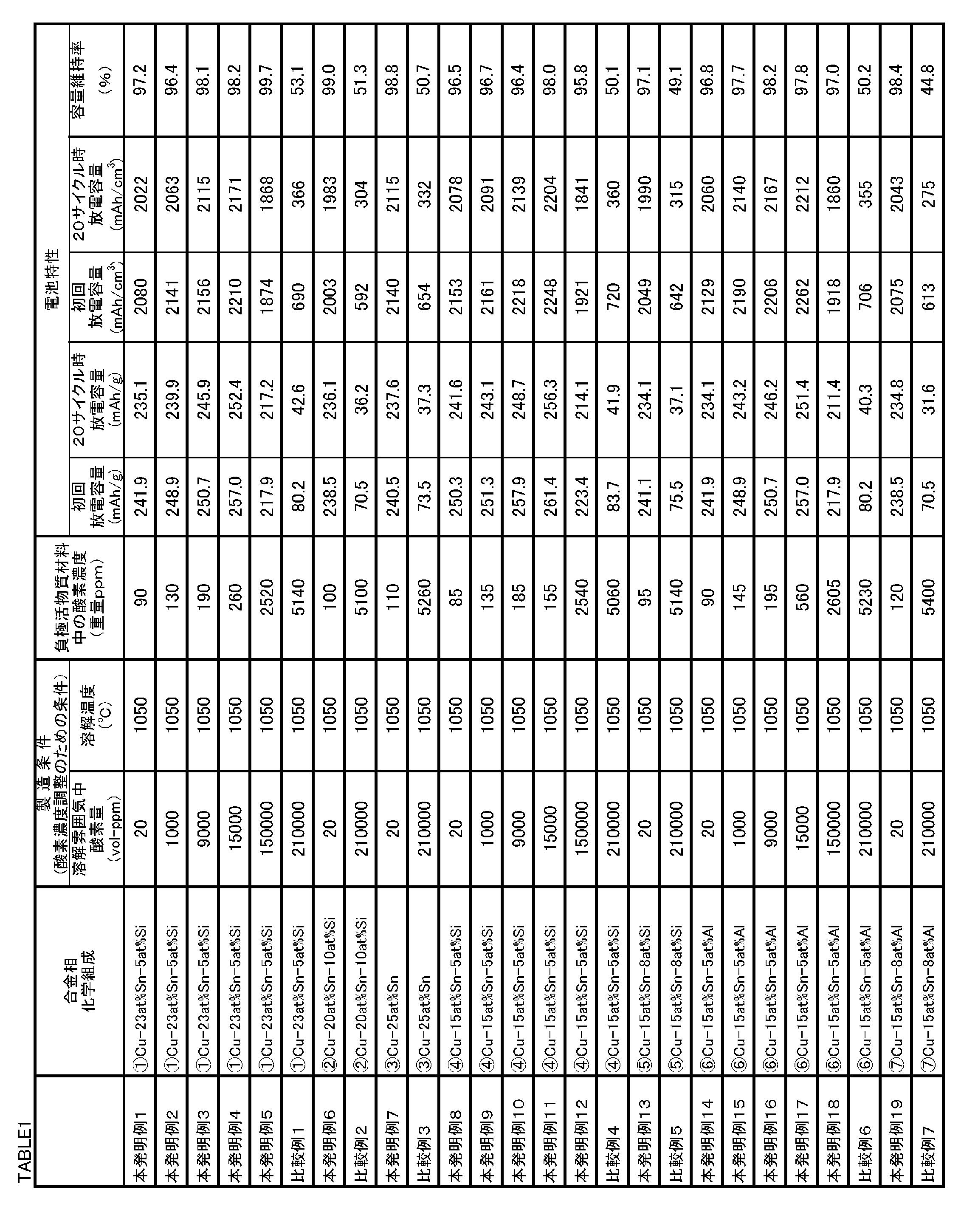
- the powdery negative electrode active material, negative electrode, and coin battery of Invention Example 1 to Invention Example 7 and Comparative Example 1 to Comparative Example 3 shown in Table 1 were produced by the following method.
- the oxygen concentration in the negative electrode active material was investigated.
- the change of the crystal structure by charging / discharging of a negative electrode active material material was confirmed.
- the discharge capacity of the battery discharge capacity per volume and discharge capacity per weight
- cycle characteristics were investigated.
- [Invention Example 1] Manufacture of negative electrode active material
- a mixture of a plurality of materials (elements) is made of boron nitride in an argon gas atmosphere so that the final chemical composition of the negative electrode active material is the chemical composition described in the “Alloy phase chemical composition” column of Table 1.
- the melt was produced by high-frequency melting in the nozzle.
- the oxygen concentration and dissolution temperature in the argon gas atmosphere were as shown in Table 1.
- the oxygen concentration was adjusted by a reduced pressure replacement method in which the operation of introducing an inert gas was repeated after the argon gas atmosphere was depressurized to 0.7 atm.
- the melting temperatures of Invention Examples 1 to 7 and Comparative Examples 1 to 3 in Table 1 were both 240 to 290 ° C.
- the liquidus temperature of an arbitrary composition of the Cu—Sn—Si based alloy can be known by creating an equilibrium diagram by thermodynamic calculation by the CALPHAD method, for example, using ThermoCalc (software name).
- SSOL5 was used for the thermodynamic database.
- the molten metal was sprayed onto a rotating copper roll to produce a rapidly solidified foil strip.
- the thickness of the foil strip was 20 to 40 ⁇ m.
- This foil strip was pulverized with a crusher (automatic mortar) to obtain an alloy powder of 45 ⁇ m or less.
- This alloy powder was used as a negative electrode active material.
- the final chemical composition of the negative electrode active material of each inventive example was as described in the “Alloy phase chemical composition” column in Table 1.
- the chemical composition of the negative electrode active material of Inventive Example 1 contained 23 at% Sn and 5 at% Si, with the balance being Cu and impurities.
- the produced negative electrode mixture slurry was applied onto a metal foil using an applicator (150 ⁇ m).
- the metal foil coated with the slurry was dried at 100 ° C. for 20 minutes.
- the dried metal foil had a coating film made of a negative electrode active material on the surface.
- the metal foil having a coating film was punched to produce a disk-shaped metal foil having a diameter of 13 mm.
- the metal foil after punching was pressed with a press pressure of 500 kgf / cm 2 to produce a plate-like negative electrode.
- the metal foil In the negative electrode used for evaluation / measurement of the negative electrode active material other than the specific crystal structure, the metal foil was a copper foil. In the negative electrode used for specifying the crystal structure, the metal foil was a nickel foil.
- a manufactured negative electrode, EC-DMC-EMC-VC-FEC as an electrolytic solution, a polyolefin separator ( ⁇ 17 mm) as a separator, and plate-like metal Li ( ⁇ 19 ⁇ 1 mmt) as a positive electrode material were prepared.
- a 2016-type coin battery was manufactured using the prepared negative electrode, electrolytic solution, separator, and positive electrode. The coin battery was assembled in a glove box in an argon atmosphere.
- the oxygen content in the negative electrode active material was measured by an active gas transport melting infrared absorption method.
- the oxygen content of Invention Example 1 was as shown in Table 1.
- an X-ray diffraction profile of the powder of the negative electrode active material was obtained using a Rigaku product name SmartLab (rotor target maximum output 9 KW; 45 kV-200 mA).
- the crystal structure of the alloy phase in the negative electrode active material was analyzed by the Rietveld method.
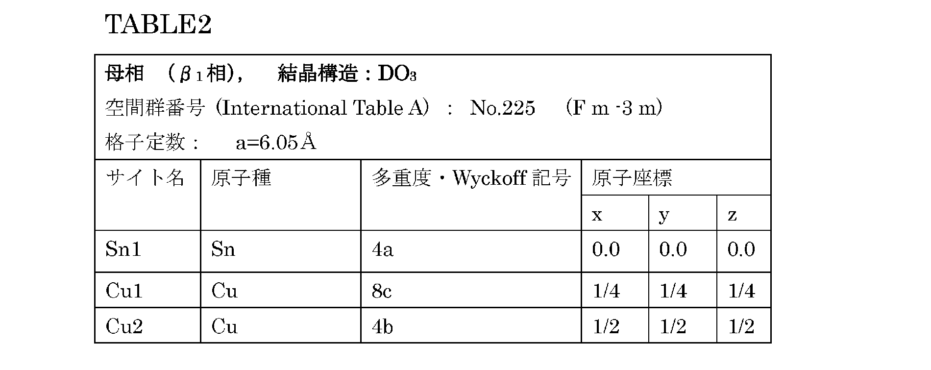
- the DO 3 regular structure is a regular structure as shown in FIG. 2A.
- Cu is mainly present at the black circle atomic sites
- Sn is mainly present at the white circle atomic sites.
- Each site may be replaced by the addition of the third element.
- Such a crystal structure is the same as that of International Table (Volume-A) No. 225 (Fm-3m) is known.
- Table 2 shows the lattice constants and atomic coordinates of the crystal structure of this space group number.
- the calculated value of the diffraction profile of the ⁇ 1 phase (DO 3 structure) of this chemical composition (hereinafter referred to as the computational profile) is obtained by Rietveld analysis. It was. Rietan-FP (program name) was used for Rietveld analysis.
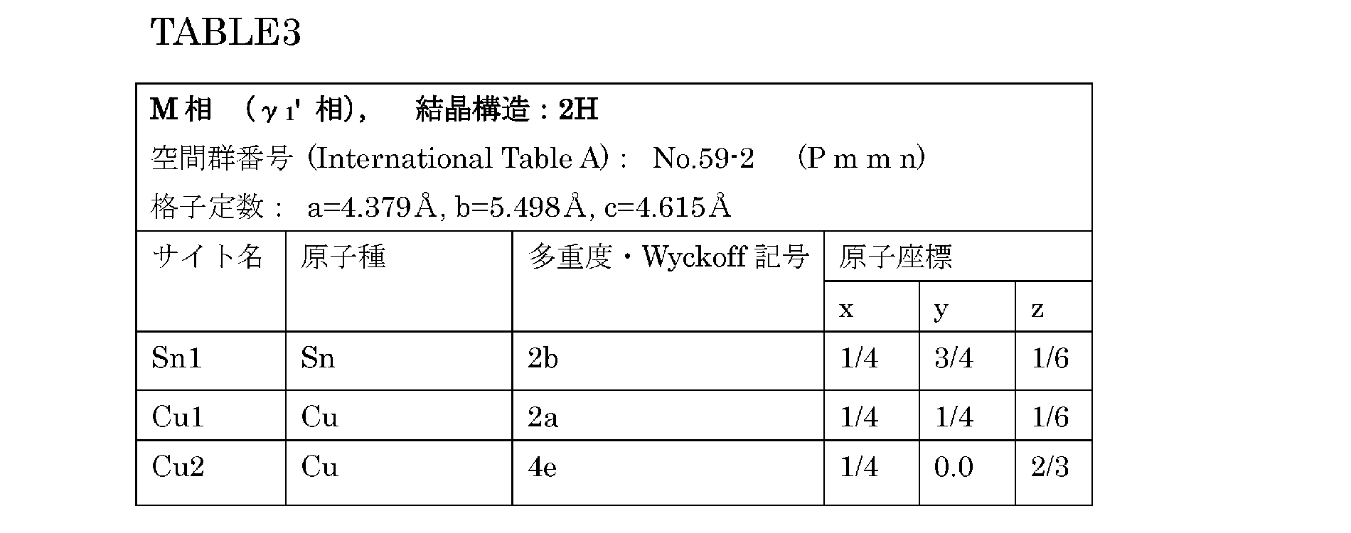
- the crystal structure of ⁇ 1 ′ is a 2H structure in the notation of the Ramsdel symbol, and the space group is No. of International Table (Volume-A). 59-2 (Pmmn). No. Table 3 shows the lattice constant and atomic coordinates of 59-2 (Pmmn).
- a calculation profile was obtained using RIEtan-FP with the crystal structure of the space group number in Table 3 as an initial structure model for Rietveld analysis.
- the negative electrode active material of Inventive Example 1 alone had a ⁇ 1 phase (DO 3 structure) that is a parent phase of the ⁇ 1 ′ phase (2H structure) that is one of the M phases.
- the above coin battery was disassembled in a glove box in an argon atmosphere, and a plate-like negative electrode (including nickel foil) was taken out from the coin battery.
- the extracted negative electrode was wrapped in mylar foil (manufactured by DuPont). Thereafter, the periphery of the mylar foil was sealed with a thermocompression bonding machine. The negative electrode sealed with mylar foil was taken out of the glove box.
- the negative electrode was attached to a non-reflective sample plate made of Rigaku (a plate cut out so that the specific crystal plane of the silicon single crystal was parallel to the measurement plane) with a hair spray to prepare a measurement sample.
- the measurement sample was set in the X-ray diffractometer described in (4) described later, and the X-ray diffraction measurement of the measurement sample was performed under the measurement conditions described in (4) described later.
- the above coin battery was fully charged in the charge / discharge test apparatus.
- the fully charged coin battery was disassembled in the glove box, and a measurement sample was prepared in the same manner as (2).
- a measurement sample was set in the X-ray diffractometer described later in (4), and the X-ray diffraction measurement of the measurement sample was performed under the measurement conditions described in (4) below.
- the above coin battery was completely discharged.
- the fully discharged coin cell was disassembled in the glove box, and a measurement sample was prepared in the same manner as (3).
- This measurement sample was set in the X-ray diffractometer described later in (4), and the X-ray diffraction measurement of the measurement sample was performed under the measurement conditions described later in (4).
- X-ray diffraction measurement was performed on the negative electrode after repeated charging and discharging with a coin battery by the same method.
- the diffraction angle 2 ⁇ is near 45.5 ° (position caused by the M phase ( ⁇ 1 ′ phase)).
- the diffraction line repeatedly and reversibly changed at the position (hereinafter referred to as the strongest diffraction line of the M phase). That is, a structural change was suggested.
- the crystal plane A shown in FIG. 2D and the crystal plane B shown in FIG. 2C are alternately stacked.
- the crystal plane B regularly shuffles due to shear stress as shown in FIGS. 2A and 2B. It shifts to the position of plane B ′.
- phase transformation M transformation
- the crystal plane A shown in FIG. 2D and the crystal plane B ′ shown in FIG. 2E are alternately stacked.
- the measured data of the X-ray diffraction profile of the negative electrode active material after charging and discharging, the calculated profile of ⁇ 1 phase (DO 3 structure), and the calculated profile of ⁇ 1 'phase (2H structure) are compared.
- the crystal structure of the negative electrode active material in the negative electrode of the present example was accompanied by M transformation or not (that is, accompanied by diffusion of the host lattice during charge / discharge).
- the intensity of the diffraction line near 43.5 ° increased by the first charge, and the intensity decreased by the subsequent discharge.
- This diffraction line can be judged from the calculation profile of RIEtan-FP to be derived from the formation of the M phase ( ⁇ 1 ′) by the M transformation as described below.
- the negative electrode of the present example contained an alloy phase that transformed into M by charging to become an M phase (2H structure) and became a parent phase (DO 3 structure) by discharging. That is, the negative electrode of this example contained an alloy phase that undergoes M transformation when occlusion of lithium ions, which are metal ions, and reverse transformation when lithium ions are released.
- the M transformation was repeated during charging and the reverse transformation was repeated during discharging.
- the doping capacity and the dedoping capacity correspond to a charging capacity and a discharging capacity when this electrode is used as a negative electrode of a lithium ion secondary battery. Therefore, the measured doping capacity was defined as charge capacity (mAh / g or mAh / cm 3 ), and the measured dedoping capacity was defined as discharge capacity (mAh / g or mAh / cm 3 ).
- the charging / discharging was repeated 20 times under the same conditions as described above.
- the capacity retention rate (%) was obtained by dividing the “discharge capacity at the time of dedoping at the 20th cycle” by the “discharge capacity at the time of dedoping at the 1st cycle” and multiplying by 100.
- the initial discharge capacity, the discharge capacity at the 20th cycle, and the capacity retention rate were as shown in Table 1.
- Example 1 of the present invention the crystal structure was specified, the oxygen concentration in the negative electrode active material, and various charge / discharge performance evaluations of the coin battery.
- Example 1 of the present invention The specific result of the crystal structure was the same as that of Example 1 of the present invention. That is, it was confirmed that the alloy phases of Invention Examples 2 to 5 and Comparative Example 1 have a crystal structure that undergoes M transformation when occlusion of lithium ions and reverse transformation when lithium ions are released.
- Table 1 shows the oxygen concentration in the negative electrode active material and the results of various charge / discharge performance evaluations of the coin battery.
- Invention Example 6 Invention Example 6, the negative electrode active material, the negative electrode, and the coin battery were the same as in Example 1 except that the final chemical composition of the negative electrode active material was changed to the composition shown in Table 1. Manufactured.
- Example 1 of the present invention the crystal structure was specified, the oxygen concentration in the negative electrode active material, and various charge / discharge performance evaluations of the coin battery.
- Example 6 The specific result of the crystal structure was the same as that of Example 1 of the present invention. That is, it was confirmed that the alloy phase of Invention Example 6 has a crystal structure that undergoes M transformation when occlusion of lithium ions and reverse transformation when lithium ions are released.
- Table 1 shows the oxygen concentration in the negative electrode active material and the results of various charge / discharge performance evaluations of the coin battery.
- Comparative Example 2 In Comparative Example 2, a negative electrode active material, a negative electrode, and a coin battery were manufactured in the same manner as in Example 6 except that the oxygen content in the dissolved atmosphere was changed to the concentration shown in Table 1.
- Example 1 of the present invention the crystal structure was specified, the oxygen concentration in the negative electrode active material, and various charge / discharge performance evaluations of the coin battery.
- Example 6 of the present invention The specific result of the crystal structure was the same as in Example 6 of the present invention. That is, it was confirmed that the alloy phase of Comparative Example 2 has a crystal structure that undergoes M transformation when occlusion of lithium ions and reverse transformation when lithium ions are released.
- Table 1 shows the oxygen concentration in the negative electrode active material and the results of various charge / discharge performance evaluations of the coin battery.
- Example 1 of the present invention the crystal structure was specified, the oxygen concentration in the negative electrode active material, and various charge / discharge performance evaluations of the coin battery.
- the alloy phase changed as follows with charge and discharge.
- M phase (2H structure) before the first charge M phase (2H structure) after the first charge
- mother phase (DO 3 structure) after the first discharge mother phase (DO 3 structure) after the first discharge
- M transformation (M2 phase) due to charging M transformation due to charging.
- the mother phase (DO 3 structure) was obtained by the discharge. That is, it was confirmed that the negative electrode of the example of the present invention has an alloy phase that undergoes M transformation when occlusion of lithium ions, which are metal ions, and reverse transformation when lithium ions are released.
- Table 1 shows the oxygen concentration in the negative electrode active material and the results of various charge / discharge performance evaluations of the coin battery.
- Comparative Example 3 In Comparative Example 3, a negative electrode active material, a negative electrode, and a coin battery were manufactured in the same manner as in Example 7 except that the oxygen content in the dissolved atmosphere was changed to the concentration shown in Table 1.
- Example 1 of the present invention the crystal structure was specified, the oxygen concentration in the negative electrode active material, and various charge / discharge performance evaluations of the coin battery.
- Example 7 of the present invention The specific result of the crystal structure was the same as Example 7 of the present invention. Therefore, it was confirmed that the alloy phase of Comparative Example 3 has a crystal structure that undergoes M transformation when occlusion of lithium ions and reverse transformation when lithium ions are released.
- Table 1 shows the oxygen concentration in the negative electrode active material and the results of various charge / discharge performance evaluations of the coin battery.
- Invention Examples 8 to 19 and Comparative Examples 4 to 7 In Invention Examples 8 to 19, except that the final chemical composition of the negative electrode active material was changed to the composition shown in Table 1, the negative electrode active material, negative electrode and A coin battery was manufactured.
- Comparative Example 4 a negative electrode active material, a negative electrode, and a coin battery were manufactured in the same manner as in Examples 8 to 12 except that the oxygen amount in the dissolved atmosphere was changed to the concentration shown in Table 1.
- Comparative Example 5 a negative electrode active material, a negative electrode, and a coin battery were manufactured in the same manner as in Example 13 except that the dissolved atmosphere oxygen amount was changed to the concentration shown in Table 1.
- Comparative Example 6 a negative electrode active material, a negative electrode, and a coin battery were manufactured in the same manner as Examples 14 to 18 except that the oxygen content in the dissolved atmosphere was changed to the concentration shown in Table 1.
- Comparative Example 7 a negative electrode active material, a negative electrode, and a coin battery were manufactured in the same manner as in Example 19 except that the oxygen content in the dissolved atmosphere was changed to the concentration shown in Table 1.
- the alloy phases of Invention Examples 8 to 19 and Comparative Examples 4 to 7 changed as follows with charge / discharge.
- M phase (2H structure) before the first charge M phase (2H structure) after the first charge
- mother phase (DO 3 structure) after the first discharge mother phase (DO 3 structure) after the first discharge
- M transformation (M2 phase) due to charging M transformation due to charging.
- the mother phase (DO 3 structure) was obtained by the discharge. That is, it was confirmed that the negative electrode of the example of the present invention has an alloy phase that undergoes M transformation when occlusion of lithium ions, which are metal ions, and reverse transformation when lithium ions are released.
- Table 1 shows the oxygen concentration in the negative electrode active material and the results of various charge / discharge performance evaluations of the coin battery.
- the amount of oxygen in the dissolution atmosphere was controlled to 160000 ppm or less, and the dissolution temperature was also appropriate.
- the oxygen concentration in the negative electrode active material was 5000 ppm or less. Therefore, both the initial discharge capacity and the 20-cycle discharge capacity were 200 mAh / g or more, and the capacity retention rate was 90% or more.
Landscapes
- Chemical & Material Sciences (AREA)
- Engineering & Computer Science (AREA)
- Materials Engineering (AREA)
- Mechanical Engineering (AREA)
- Metallurgy (AREA)
- Organic Chemistry (AREA)
- Chemical Kinetics & Catalysis (AREA)
- Electrochemistry (AREA)
- General Chemical & Material Sciences (AREA)
- Manufacturing & Machinery (AREA)
- Composite Materials (AREA)
- Battery Electrode And Active Subsutance (AREA)
Abstract
Description
(単位胞の体積膨張率)=[(金属イオン吸蔵時の単位胞の体積)-(金属イオン放出時の単位胞の体積)]/(金属イオン放出時の単位胞の体積)×100・・・(1)
(単位胞の体積収縮率)=[(金属イオン吸蔵時の単位胞の体積)-(金属イオン放出時の単位胞の体積)]/(金属イオン吸蔵時の単位胞の体積)×100・・・(2)
式(1)及び式(2)中の「金属イオン放出時の単位胞の体積」には、吸蔵時の単位胞の結晶格子範囲に対応する放出時の単位胞の体積が代入される。
本発明の実施の形態に係る負極活物質材料は、合金相を含有する。さらに、負極活物質材料の酸素含有量は5000ppm以下である。
この合金相は、上述のとおり、Liイオンに代表される金属イオンを放出するとき、又は、金属イオンを吸蔵するとき、熱弾性型無拡散変態する。熱弾性型無拡散変態は、熱弾性型マルテンサイト変態とも呼ばれる。以下、本明細書では、熱弾性型マルテンサイト変態を単に「M変態」といい、マルテンサイト相を単に「M相」という。金属イオンを吸蔵又は放出するときにM変態する合金相を、「特定合金相」ともいう。
上述の特定合金相の化学組成は、M変態及び逆変態時の結晶構造が上記結晶構造を含有すれば、特に限定されない。
上記特定合金相が金属イオンの吸蔵及び放出に伴ってM変態又は逆変態する場合、特定合金相の単位胞の好ましい体積膨張収縮率は20%以下である。この場合、金属イオンの吸蔵及び放出に伴う体積変化による歪を十分に緩和することができる。特定合金相の単位胞のさらに好ましい体積膨張収縮率は10%以下であり、さらに好ましくは5%以下である。
(1)負極活物質材料が含有する相(合金相を含む)の結晶構造は、X線回折装置を用いて得られたX線回折プロファイルに基づいて、リートベルト法により解析可能である。具体的には、次の方法により、結晶構造を解析する。
本発明の実施の形態に係る負極活物質材料の酸素含有量は、5000ppm(質量ppm)以下である。酸素含有量を5000ppm以下とすることにより、容量維持率が向上し、充放電サイクル特性が向上する。これは、以下の理由によるものと考えられる。
上記特定合金相を含有する負極活物質材料、及び、その負極活物質材料を用いた負極及び電池の製造方法について説明する。
本発明の実施の形態に係る負極活物質材料を用いた負極は、当業者に周知の方法で製造することができる。
本実施形態による非水電解質二次電池は、上述の負極と、正極と、セパレータと、電解液又は電解質とを備える。電池の形状は、円筒型、角形であってもよいし、コイン型、シート型等でもよい。本実施形態の電池は、ポリマー電池等の固体電解質を利用した電池でもよい。
[負極活物質材料の製造]
負極活物質材料の最終的な化学組成が、表1中の「合金相化学組成」欄に記載の化学組成となるように、複数の素材(元素)の混合物をアルゴンガス雰囲気中の窒化ホウ素製のノズル中で高周波溶解させ、溶湯を製造した。アルゴンガス雰囲気中の酸素濃度および溶解温度は、表1に記載の通りとした。この酸素濃度の調整は、アルゴンガス雰囲気を0.7atmに減圧した後、不活性ガスを導入する操作を繰り返す減圧置換法により行った。表1中の本発明例1~7及び比較例1~3の溶解温度はいずれも、溶製された負極活物質材料の液相線温度より240~290℃高い温度であった。Cu-Sn-Si系合金の任意の組成の液相線温度は、熱力学計算による平衡状態図をCALPHAD法によって、たとえばThermoCalc(ソフト名)を用いて作成することによって知ることができる。この場合、熱力学データベースには、SSOL5を用いた。
上述の粉末状の負極活物質材料と、導電助剤としてのアセチレンブラック(AB)と、バインダとしてのスチレンブタジエンゴム(SBR)(2倍希釈液)と、増粘剤としてのカルボキシメチルセルロース(CMC)とを、質量比75:15:10:5(配合量は1g:0.2g:0.134g:0.067g)で混合した。そして、混練機を用いて、スラリ濃度が27.2%となるように混合物に蒸留水を加えて負極合剤スラリを製造した。スチレンブタジエンゴムは水で2倍に希釈されたものを使用しているため、秤量上、0.134gのスチレンブタジエンゴムが配合された。
結晶構造の特定に用いる負極では、金属箔はニッケル箔とした。
製造された負極と、電解液としてEC-DMC-EMC-VC-FECと、セパレータとしてポリオレフィン製セパレータ(φ17mm)と、正極材として板状の金属Li(φ19×1mmt)とを準備した。準備された負極、電解液、セパレータ、正極を用いて、2016型のコイン電池を製造した。コイン電池の組み立てをアルゴン雰囲気中のグローブボックス内で行った。
負極活物質材料中の酸素含有量は、活性ガス搬送融解赤外線吸収法により測定した。本発明例1の酸素含有量は、表1に示す通りであった。
負極に使用する前の粉末状の負極活物質材料と、初回充電前の負極中の負極活物質材料と、1~5回充放電した後の負極中の負極活物質材料の結晶構造を、次の方法により特定した。対象となる負極活物質材料に対してX線回折測定を実施して、実測データを得た。そして、得られた実測データに基づいて、リートベルト法により、対象となる負極活物質材料に含まれる結晶構造を特定した。さらに具体的には、次の方法により結晶構造を特定した。
負極に使用される前の負極活物質材料の粉末に対してX線回折測定を実施して、X線回折プロファイルの実測データを得た。
充電前の負極内の負極活物質材料の結晶構造についても、(1)と同じ方法により特定した。実測のX回折プロファイルは、次の方法で測定した。
1~5回の充電後及び1~5回の放電後の負極内の負極活物質材料の結晶構造についても、(1)と同じ方法により特定した。実測のX回折プロファイルは、次の方法で測定した。
・装置:リガク製 SmartLab
・X線管球:Cu-Kα線
・X線出力:45kV,200mA
・入射側モノクロメータ:ヨハンソン素子(Cu-Kα2線及びCu-Kβ線をカット)
・光学系:Bragg-Brentano Geometry
・入射平行スリット:5.0degree
・入射スリット:1/2degree
・長手制限スリット:10.0mm
・受光スリット1:8.0mm
・受光スリット2:13.0mm
・受光平行スリット:5.0degree
・ゴニオメータ:SmartLabゴニオメータ
・X線源-ミラー間距離:90.0mm
・X線源-選択スリット間距離:114.0mm
・X線源-試料間距離:300.0mm
・試料-受光スリット1間距離:187.0mm
・試料-受光スリット2間距離:300.0mm
・受光スリット1-受光スリット2間距離:113.0mm
・試料-検出器間距離:331.0mm
・検出器:D/Tex Ultra
・スキャンレンジ:10-120degrees、または、10-90degrees
・スキャンステップ:0.02degrees
・スキャンモード:連続スキャン
・スキャン速度:2degrees/min.または、2.5degrees/min.
(5-1)
(1)、(2)及び(3)で得られたX線回折データから、負極活物質材料と電解液との間で大きな化学反応が進行していないことを確認できた。
「充電後の負極活物質材料」及び、「放電後の負極活物質材料」のX線回折プロファイルから、回折角2θが45.5°近傍(M相(γ1'相)に起因する位置)の位置(以下、M相の最強回折線という)において、回折線が繰り返し可逆的に変化した。すなわち、構造変化が示唆された。
そこで、「充電後の負極活物質材料」及び「放電後の負極活物質材料」の結晶構造をリートベルト法を用いて特定した。
次に、本発明例1の電池の放電容量及びサイクル特性を評価した。
本発明例2~5および比較例1では、溶解雰囲気中酸素量を表1に示す濃度に変更した以外は、本発明例1と同様にして、負極活物質材料、負極及びコイン電池を製造した。
本発明例6では、負極活物質材料の最終的な化学組成が、表1に記載の組成となるようにした以外は、本発明例1と同様にして、負極活物質材料、負極及びコイン電池を製造した。
比較例2では、溶解雰囲気中酸素量を表1に記載の濃度に変更した以外は、本発明例6と同様にして、負極活物質材料、負極及びコイン電池を製造した。
本発明例7では、負極活物質材料の最終的な化学組成が、表1に記載の組成となるようにした以外は、本発明例1と同様にして、負極活物質材料、負極及びコイン電池を製造した。
比較例3では、溶解雰囲気中酸素量を表1に記載の濃度に変更した以外は、本発明例7と同様にして、負極活物質材料、負極及びコイン電池を製造した。
本発明例8~19では、負極活物質材料の最終的な化学組成が、表1に記載の組成となるようにした以外は、本発明例1と同様にして、負極活物質材料、負極及びコイン電池を製造した。
Claims (11)
- 負極活物質材料であって、
金属イオンを放出するとき又は前記金属イオンを吸蔵するときに熱弾性型無拡散変態する合金相を備え、
前記負極活物質材料の酸素含有量が5000質量ppm以下である、負極活物質材料。 - 請求項1に記載の負極活物質材料であって、
前記合金相は、前記金属イオンを吸蔵するときに前記熱弾性型無拡散変態し、前記金属イオンを放出するときに逆変態する、負極活物質材料。 - 請求項2に記載の負極活物質材料であって、
前記熱弾性型無拡散変態後の前記合金相は、Ramsdell表記で2Hである結晶構造を含有し、
前記逆変態後の前記合金相は、Strukturbericht表記でDO3である結晶構造を含有する、負極活物質材料。 - 請求項2又は請求項3に記載の負極活物質材料であって、
前記合金相は、Cuと、Snとを含有する、負極活物質材料。 - 請求項4に記載の負極活物質材料であって、
前記合金相は、10~20at%又は21~27at%のSnを含有し、残部はCu及び不純物からなる、負極活物質材料。 - 請求項4に記載の負極活物質材料であってさらに、
前記合金相は、Cuの一部に代えて、Ti、V、Cr、Mn、Fe、Co、Ni、Zn、Al、Si、B及びCからなる群から選択される1種以上を含有する、負極活物質材料。 - 請求項6に記載の負極活物質材料であって、
前記合金相は、
Sn:10~35at%と、
Ti:9.0at%以下、V:49.0at%以下、Cr:49.0at%以下、Mn:9.0at%以下、Fe:49.0at%以下、Co:49.0at%以下、Ni:9.0at%以下、Zn:29.0at%以下、Al:49.0at%以下、Si:49.0at%以下、B:5.0at%以下、及び、C:5.0at%以下からなる群から選択される1種以上とを含有し、
残部はCu及び不純物からなる、負極活物質材料。 - 負極活物質材料であって、
10~20at%又は21~27at%のSnを含有し、残部はCu及び不純物からなる合金相を備え、
前記負極活物質材料の酸素含有量が5000質量ppm以下である、負極活物質材料。 - 負極活物質材料であって、
Sn:10~35at%と、Ti:9.0at%以下、V:49.0at%以下、Cr:49.0at%以下、Mn:9.0at%以下、Fe:49.0at%以下、Co:49.0at%以下、Ni:9.0at%以下、Zn:29.0at%以下、Al:49.0at%以下、Si:49.0at%以下、B:5.0at%以下、及び、C:5.0at%以下からなる群から選択される1種以上とを含有し、残部はCu及び不純物からなる合金相を備え、
前記負極活物質材料の酸素含有量が5000質量ppm以下である、負極活物質材料。 - 請求項1~請求項9のいずれか1項に記載の負極活物質材料を含む負極。
- 請求項10に記載の負極を備える電池。
Priority Applications (7)
| Application Number | Priority Date | Filing Date | Title |
|---|---|---|---|
| KR1020167026188A KR20160124221A (ko) | 2014-02-25 | 2015-02-25 | 음극 활물질 재료, 음극 및 전지 |
| EP15755086.4A EP3113259B1 (en) | 2014-02-25 | 2015-02-25 | Negative electrode active substance material, negative electrode, and cell |
| CN201580009872.7A CN106030867B (zh) | 2014-02-25 | 2015-02-25 | 负极活性物质材料、负极和电池 |
| PL15755086T PL3113259T3 (pl) | 2014-02-25 | 2015-02-25 | Materiał substancji aktywnej elektrody ujemnej, elektroda ujemna i ogniwo |
| JP2016505075A JP6265259B2 (ja) | 2014-02-25 | 2015-02-25 | 負極活物質材料、負極及び電池 |
| KR1020187027634A KR102162393B1 (ko) | 2014-02-25 | 2015-02-25 | 음극 활물질 재료, 음극 및 전지 |
| US15/115,918 US10270092B2 (en) | 2014-02-25 | 2015-02-25 | Negative electrode active material, negative electrode and battery |
Applications Claiming Priority (2)
| Application Number | Priority Date | Filing Date | Title |
|---|---|---|---|
| JP2014034262 | 2014-02-25 | ||
| JP2014-034262 | 2014-02-25 |
Publications (1)
| Publication Number | Publication Date |
|---|---|
| WO2015129270A1 true WO2015129270A1 (ja) | 2015-09-03 |
Family
ID=54008603
Family Applications (1)
| Application Number | Title | Priority Date | Filing Date |
|---|---|---|---|
| PCT/JP2015/000964 Ceased WO2015129270A1 (ja) | 2014-02-25 | 2015-02-25 | 負極活物質材料、負極及び電池 |
Country Status (8)
| Country | Link |
|---|---|
| US (1) | US10270092B2 (ja) |
| EP (1) | EP3113259B1 (ja) |
| JP (1) | JP6265259B2 (ja) |
| KR (2) | KR20160124221A (ja) |
| CN (1) | CN106030867B (ja) |
| HU (1) | HUE050836T2 (ja) |
| PL (1) | PL3113259T3 (ja) |
| WO (1) | WO2015129270A1 (ja) |
Cited By (7)
| Publication number | Priority date | Publication date | Assignee | Title |
|---|---|---|---|---|
| WO2017164396A1 (ja) * | 2016-03-25 | 2017-09-28 | 日本碍子株式会社 | 銅合金及びその製造方法 |
| WO2017213147A1 (ja) * | 2016-06-10 | 2017-12-14 | 新日鐵住金株式会社 | 負極活物質材料、負極及び電池 |
| JP2018133184A (ja) * | 2017-02-15 | 2018-08-23 | 新日鐵住金株式会社 | 負極活物質材料、負極及び電池 |
| WO2019017349A1 (ja) * | 2017-07-18 | 2019-01-24 | 新日鐵住金株式会社 | 負極活物質材料、負極及び電池 |
| JP2019167573A (ja) * | 2018-03-22 | 2019-10-03 | 国立大学法人横浜国立大学 | Cu−Sn−Si系超弾性合金及びその製造方法 |
| JP2019199632A (ja) * | 2018-05-15 | 2019-11-21 | 大同特殊鋼株式会社 | 精錬方法 |
| WO2020149404A1 (ja) * | 2019-01-17 | 2020-07-23 | 日本製鉄株式会社 | 負極活物質材料、負極及び電池 |
Families Citing this family (4)
| Publication number | Priority date | Publication date | Assignee | Title |
|---|---|---|---|---|
| JP5729520B2 (ja) * | 2012-08-27 | 2015-06-03 | 新日鐵住金株式会社 | 負極活物質材料 |
| CN109155404B (zh) * | 2016-05-18 | 2022-06-17 | 日本制铁株式会社 | 负极活性物质材料、负极及电池 |
| JP7006739B1 (ja) * | 2020-08-28 | 2022-01-24 | 住友金属鉱山株式会社 | 合金粉及びその製造方法、並びに有価金属の回収方法 |
| US20230369579A1 (en) * | 2020-09-30 | 2023-11-16 | Panasonic Intellectual Property Management Co., Ltd. | Positive electrode active material for secondary batteries, and secondary battery |
Citations (6)
| Publication number | Priority date | Publication date | Assignee | Title |
|---|---|---|---|---|
| JP2001297766A (ja) * | 2000-04-14 | 2001-10-26 | Sumitomo Metal Ind Ltd | 非水電解質二次電池とその負極材料および該材料の製法 |
| JP2002251992A (ja) * | 2001-02-22 | 2002-09-06 | Kureha Chem Ind Co Ltd | 非水溶媒二次電池用電極材料、電極および二次電池 |
| JP2006294278A (ja) * | 2005-04-06 | 2006-10-26 | Sony Corp | 負極および電池 |
| JP2008503048A (ja) * | 2004-06-16 | 2008-01-31 | インダストリー−アカデミック コーポレーション ファンデーション キョンサン ナショナル ユニバーシティ | 電池の集電体およびアノード用のハイブリッド超弾性金属−金属硫化物材料 |
| JP2010161078A (ja) * | 1999-07-01 | 2010-07-22 | Panasonic Corp | 非水電解質二次電池 |
| WO2014034104A1 (ja) * | 2012-08-27 | 2014-03-06 | 新日鐵住金株式会社 | 負極活物質材料 |
Family Cites Families (4)
| Publication number | Priority date | Publication date | Assignee | Title |
|---|---|---|---|---|
| JP4270109B2 (ja) * | 2004-11-05 | 2009-05-27 | ソニー株式会社 | 電池 |
| KR100859687B1 (ko) | 2007-03-21 | 2008-09-23 | 삼성에스디아이 주식회사 | 리튬 이차 전지용 음극 활물질 및 그를 포함하는 리튬 이차전지 |
| JP5345974B2 (ja) * | 2010-06-01 | 2013-11-20 | Jx日鉱日石金属株式会社 | 圧延銅合金箔、並びにこれを用いた負極集電体、負極板及び二次電池 |
| JP5884573B2 (ja) * | 2011-09-30 | 2016-03-15 | 大同特殊鋼株式会社 | リチウムイオン電池用負極活物質及びこれを用いたリチウムイオン電池用負極 |
-
2015
- 2015-02-25 KR KR1020167026188A patent/KR20160124221A/ko not_active Ceased
- 2015-02-25 WO PCT/JP2015/000964 patent/WO2015129270A1/ja not_active Ceased
- 2015-02-25 CN CN201580009872.7A patent/CN106030867B/zh active Active
- 2015-02-25 HU HUE15755086A patent/HUE050836T2/hu unknown
- 2015-02-25 KR KR1020187027634A patent/KR102162393B1/ko active Active
- 2015-02-25 US US15/115,918 patent/US10270092B2/en active Active
- 2015-02-25 JP JP2016505075A patent/JP6265259B2/ja active Active
- 2015-02-25 EP EP15755086.4A patent/EP3113259B1/en active Active
- 2015-02-25 PL PL15755086T patent/PL3113259T3/pl unknown
Patent Citations (6)
| Publication number | Priority date | Publication date | Assignee | Title |
|---|---|---|---|---|
| JP2010161078A (ja) * | 1999-07-01 | 2010-07-22 | Panasonic Corp | 非水電解質二次電池 |
| JP2001297766A (ja) * | 2000-04-14 | 2001-10-26 | Sumitomo Metal Ind Ltd | 非水電解質二次電池とその負極材料および該材料の製法 |
| JP2002251992A (ja) * | 2001-02-22 | 2002-09-06 | Kureha Chem Ind Co Ltd | 非水溶媒二次電池用電極材料、電極および二次電池 |
| JP2008503048A (ja) * | 2004-06-16 | 2008-01-31 | インダストリー−アカデミック コーポレーション ファンデーション キョンサン ナショナル ユニバーシティ | 電池の集電体およびアノード用のハイブリッド超弾性金属−金属硫化物材料 |
| JP2006294278A (ja) * | 2005-04-06 | 2006-10-26 | Sony Corp | 負極および電池 |
| WO2014034104A1 (ja) * | 2012-08-27 | 2014-03-06 | 新日鐵住金株式会社 | 負極活物質材料 |
Non-Patent Citations (1)
| Title |
|---|
| See also references of EP3113259A4 * |
Cited By (16)
| Publication number | Priority date | Publication date | Assignee | Title |
|---|---|---|---|---|
| CN107923000B (zh) * | 2016-03-25 | 2021-02-12 | 日本碍子株式会社 | 铜合金及其制造方法 |
| JPWO2017164396A1 (ja) * | 2016-03-25 | 2018-03-29 | 日本碍子株式会社 | 銅合金及びその製造方法 |
| CN107923000A (zh) * | 2016-03-25 | 2018-04-17 | 日本碍子株式会社 | 铜合金及其制造方法 |
| WO2017164396A1 (ja) * | 2016-03-25 | 2017-09-28 | 日本碍子株式会社 | 銅合金及びその製造方法 |
| US10954586B2 (en) | 2016-03-25 | 2021-03-23 | Ngk Insulators, Ltd. | Copper alloy and method for producing same |
| WO2017213147A1 (ja) * | 2016-06-10 | 2017-12-14 | 新日鐵住金株式会社 | 負極活物質材料、負極及び電池 |
| JPWO2017213147A1 (ja) * | 2016-06-10 | 2019-04-18 | 新日鐵住金株式会社 | 負極活物質材料、負極及び電池 |
| JP2018133184A (ja) * | 2017-02-15 | 2018-08-23 | 新日鐵住金株式会社 | 負極活物質材料、負極及び電池 |
| WO2019017349A1 (ja) * | 2017-07-18 | 2019-01-24 | 新日鐵住金株式会社 | 負極活物質材料、負極及び電池 |
| JP6515363B1 (ja) * | 2017-07-18 | 2019-05-22 | 日本製鉄株式会社 | 負極活物質材料、負極及び電池 |
| JP2019167573A (ja) * | 2018-03-22 | 2019-10-03 | 国立大学法人横浜国立大学 | Cu−Sn−Si系超弾性合金及びその製造方法 |
| JP2019199632A (ja) * | 2018-05-15 | 2019-11-21 | 大同特殊鋼株式会社 | 精錬方法 |
| WO2020149404A1 (ja) * | 2019-01-17 | 2020-07-23 | 日本製鉄株式会社 | 負極活物質材料、負極及び電池 |
| JPWO2020149404A1 (ja) * | 2019-01-17 | 2021-02-18 | 日本製鉄株式会社 | 負極活物質材料、負極及び電池 |
| CN113316559A (zh) * | 2019-01-17 | 2021-08-27 | 日本制铁株式会社 | 负极活性物质材料、负极和电池 |
| CN113316559B (zh) * | 2019-01-17 | 2023-06-06 | 日本制铁株式会社 | 负极活性物质材料、负极和电池 |
Also Published As
| Publication number | Publication date |
|---|---|
| PL3113259T3 (pl) | 2020-09-21 |
| JPWO2015129270A1 (ja) | 2017-03-30 |
| JP6265259B2 (ja) | 2018-01-24 |
| US10270092B2 (en) | 2019-04-23 |
| HUE050836T2 (hu) | 2021-01-28 |
| EP3113259A1 (en) | 2017-01-04 |
| KR20160124221A (ko) | 2016-10-26 |
| US20170170470A1 (en) | 2017-06-15 |
| EP3113259A4 (en) | 2017-08-09 |
| CN106030867A (zh) | 2016-10-12 |
| KR20180108899A (ko) | 2018-10-04 |
| EP3113259B1 (en) | 2020-05-27 |
| KR102162393B1 (ko) | 2020-10-06 |
| CN106030867B (zh) | 2019-05-21 |
Similar Documents
| Publication | Publication Date | Title |
|---|---|---|
| JP6265259B2 (ja) | 負極活物質材料、負極及び電池 | |
| JP5729520B2 (ja) | 負極活物質材料 | |
| JP6350646B2 (ja) | 負極活物質材料、負極及び電池 | |
| JP6365658B2 (ja) | 複合粒子、負極及び電池 | |
| JP6737305B2 (ja) | 負極活物質材料、負極及び電池 | |
| JP6331463B2 (ja) | 負極活物質材料 | |
| JP6265258B2 (ja) | 負極活物質材料、負極及び電池 |
Legal Events
| Date | Code | Title | Description |
|---|---|---|---|
| 121 | Ep: the epo has been informed by wipo that ep was designated in this application |
Ref document number: 15755086 Country of ref document: EP Kind code of ref document: A1 |
|
| ENP | Entry into the national phase |
Ref document number: 2016505075 Country of ref document: JP Kind code of ref document: A |
|
| WWE | Wipo information: entry into national phase |
Ref document number: 15115918 Country of ref document: US |
|
| REEP | Request for entry into the european phase |
Ref document number: 2015755086 Country of ref document: EP |
|
| WWE | Wipo information: entry into national phase |
Ref document number: 2015755086 Country of ref document: EP |
|
| NENP | Non-entry into the national phase |
Ref country code: DE |
|
| ENP | Entry into the national phase |
Ref document number: 20167026188 Country of ref document: KR Kind code of ref document: A |