WO2015129290A1 - 波長冗長装置及び波長冗長方法 - Google Patents
波長冗長装置及び波長冗長方法 Download PDFInfo
- Publication number
- WO2015129290A1 WO2015129290A1 PCT/JP2015/050150 JP2015050150W WO2015129290A1 WO 2015129290 A1 WO2015129290 A1 WO 2015129290A1 JP 2015050150 W JP2015050150 W JP 2015050150W WO 2015129290 A1 WO2015129290 A1 WO 2015129290A1
- Authority
- WO
- WIPO (PCT)
- Prior art keywords
- signal
- client
- redundant
- transponder
- wavelength
- Prior art date
- Legal status (The legal status is an assumption and is not a legal conclusion. Google has not performed a legal analysis and makes no representation as to the accuracy of the status listed.)
- Ceased
Links
Images



Classifications
-
- H—ELECTRICITY
- H04—ELECTRIC COMMUNICATION TECHNIQUE
- H04J—MULTIPLEX COMMUNICATION
- H04J14/00—Optical multiplex systems
- H04J14/02—Wavelength-division multiplex systems
- H04J14/0227—Operation, administration, maintenance or provisioning [OAMP] of WDM networks, e.g. media access, routing or wavelength allocation
- H04J14/0254—Optical medium access
- H04J14/0256—Optical medium access at the optical channel layer
- H04J14/0257—Wavelength assignment algorithms
-
- H—ELECTRICITY
- H04—ELECTRIC COMMUNICATION TECHNIQUE
- H04Q—SELECTING
- H04Q11/00—Selecting arrangements for multiplex systems
- H04Q11/0001—Selecting arrangements for multiplex systems using optical switching
- H04Q11/0062—Network aspects
- H04Q11/0066—Provisions for optical burst or packet networks
-
- H—ELECTRICITY
- H04—ELECTRIC COMMUNICATION TECHNIQUE
- H04J—MULTIPLEX COMMUNICATION
- H04J14/00—Optical multiplex systems
- H04J14/02—Wavelength-division multiplex systems
- H04J14/0287—Protection in WDM systems
- H04J14/0293—Optical channel protection
- H04J14/0294—Dedicated protection at the optical channel (1+1)
-
- H—ELECTRICITY
- H04—ELECTRIC COMMUNICATION TECHNIQUE
- H04J—MULTIPLEX COMMUNICATION
- H04J14/00—Optical multiplex systems
- H04J14/02—Wavelength-division multiplex systems
- H04J14/0287—Protection in WDM systems
- H04J14/0297—Optical equipment protection
-
- H—ELECTRICITY
- H04—ELECTRIC COMMUNICATION TECHNIQUE
- H04Q—SELECTING
- H04Q11/00—Selecting arrangements for multiplex systems
- H04Q11/0001—Selecting arrangements for multiplex systems using optical switching
- H04Q11/0005—Switch and router aspects
- H04Q2011/0007—Construction
- H04Q2011/0016—Construction using wavelength multiplexing or demultiplexing
-
- H—ELECTRICITY
- H04—ELECTRIC COMMUNICATION TECHNIQUE
- H04Q—SELECTING
- H04Q11/00—Selecting arrangements for multiplex systems
- H04Q11/0001—Selecting arrangements for multiplex systems using optical switching
- H04Q11/0062—Network aspects
- H04Q2011/0079—Operation or maintenance aspects
- H04Q2011/0081—Fault tolerance; Redundancy; Recovery; Reconfigurability
Definitions
- the present invention relates to a wavelength redundancy device and a wavelength redundancy method in a wavelength division multiplexing optical transmission system.
- the transmission speed per transponder is 10 Gbps to 40 Gbps, 100 Gbps, 400 Gbps. Development is progressing rapidly. As a method of increasing the communication capacity of the submarine cable, a conventional optical fiber is utilized, and a part of the used 10 Gbps band is evacuated by new 40 Gbps or 100 Gbps by migration, or originally vacant. An upgrade method is generally used so as to effectively utilize the bandwidth. In response to such technical trends, in recent years, wavelength multiplexing optical transmission systems in which transponders having different transmission rates are mixed are increasing.
- the wavelength division multiplexing optical transmission system has a redundant system in order to protect a client signal transmitted on that wavelength.
- the system configuration was switchable.
- Patent Document 1 discloses optical couplers 11-1 to 11-n for branching signals for n channels received from an external device in two directions for each channel, one for the active system and one for the standby system.
- the transponders 12-1 to 12-n that convert the signals for the working system branched at -1 to 11-n into optical signals of ⁇ 1 to ⁇ n and send them, and the optical couplers 11-1 to 11-n
- An optical switch 13 that selects and transmits a standby system signal from the branched standby system signals, and a transponder 12- (n + 1) that converts the standby system signal transmitted from the optical switch 13 into an optical signal of ⁇ n + 1 and transmits it. ) Is described (see FIG. 1 of Patent Document 1).
- the optical switch 13 When a failure is detected at one wavelength of the optical signals of ⁇ 1 to ⁇ n transmitted from the transponders 12-1 to 12-n, the optical switch 13 is placed at the wavelength at which the failure is detected. A standby signal corresponding to the signal is selected and output to the transponder 12- (n + 1). The transponder 12- (n + 1) transmits this output signal using ⁇ n + 1 (see FIG. 4 of Patent Document 1).
- the transponder 12-1 is a 10 Gbps transponder
- the transponder 12-2 is a 40 Gbps transponder
- the transponder 12-3 is a 100 Gbps transponder, that is, 100 Gbps, 40 Gbps, 10 Gbps, and so on.
- wavelength redundancy devices optical couplers 11-1 to 11-n, optical switches 13, transponders 12- (N + 1) etc.
- the present invention has been made to solve the above-described problems.
- a wavelength redundancy device that does not need to be installed for each WDM transmission rate is obtained. With the goal.
- WDM line signals having different wavelengths are output by a plurality of working transponders that process input client signals, and a plurality of types of transmission speeds of WDM line signals are mixed.
- it outputs a client signal to the current transponder, and also has an optical coupler that outputs a redundant client signal that is a branch of the client signal, and a client interface, and processes signals input from the client interface.
- the redundant transponder output as the redundant WDM line signal and the redundant client signal output from the optical coupler are input, and the signal of the transmission rate suitable for the client interface of the redundant transponder is selectively selected.
- the selection switching unit When a failure occurs in the wavelength of the WDM line signal output from the active transponder, the selection switching unit outputs the WDM line signal of the wavelength in which the failure has occurred to the client that is input to the active transponder
- the redundant client signal of the signal is selected and output as a redundant client signal having a transmission rate suitable for the client interface of the redundant transponder.
- the redundant transponder has a transmission rate suitable for the client interface output by the selection switching unit.
- the redundant client signal is processed to output a redundant WDM line signal.
- WDM line signals having different wavelengths are output by a plurality of working transponders that process input client signals, and a plurality of transmission speeds of WDM line signals are mixed.
- a client signal is output to a current transponder, and a redundant client signal obtained by branching the client signal is output, and a client interface is provided to process a signal input from the client interface.
- a redundant transponder output as a redundant WDM line signal and a redundant client signal output from an optical coupler are input, and a signal having a transmission rate suitable for the client interface of the redundant transponder is selectively output.
- the selection switching unit When a failure occurs in the wavelength of the WDM line signal output from the active transponder, the selection switching unit displays the WDM line signal of the wavelength in which the failure has occurred.
- the present invention it is not necessary to install each wavelength redundancy device for each WDM transmission speed, and it is possible to effectively use the band and reduce the cost and installation space required for the wavelength redundancy device.
- FIG. 1 shows a configuration example of a terminal apparatus provided with a wavelength redundancy apparatus according to Embodiment 1 of the present invention.
- the terminal equipment includes optical couplers 2a to 2c for branching client signals 1a to 1c transmitted from the backhaul side, a 10 Gbps transponder 3a (active transponder) having one 10 Gbps base client interface, and a 10 Gbps base client.
- a 40 Gbps transponder 3b (working transponder) having four interfaces, a 100 Gbps transponder 3c (working transponder) having ten 10 Gbps-based client interfaces, and an M: N switch 40 (selectively outputting an input signal) And a redundant 100 Gbps transponder 50 having ten 10 Gbps-based client interfaces.
- FIG. 1 only components related to redundancy are shown, and elements that perform processing such as wavelength multiplexing and amplification are omitted.
- the client signal 1a is a single 10 Gbps signal corresponding to the 10 Gbps transponder 3a.
- the client signal 1b is a 10 Gbps signal, corresponds to the 40 Gbps transponder 3b, and is transmitted in four lines.
- the client signal 1c is a 10 Gbps signal, corresponds to the 100 Gbps transponder 3c, and is transmitted by ten signals.
- the client signal 1a is branched by the optical coupler 2a into the 10 Gbps transponder 3a direction and the M: N switch 40 direction.
- the client signal 1b is branched by the optical coupler 2b in the 40 Gbps transponder 3b direction and the M: N switch 40 direction.
- the client signal 1c is branched by the optical coupler 2c into the 100 Gbps transponder 3c direction and the M: N switch 40 direction.
- the one directed to the M: N switch 40 is branched as a redundant client signal.
- the signal going to the M: N switch 40 and the signal going to the 10 Gbps transponder 3a, the 40 Gbps transponder 3b, or the 100 Gbps transponder 3c are substantially the same signal, and both are described as client signals 1a to 1c. .
- 10Gbps transponder 3a is a client signal 1a is inputted through the optical coupler 2a, to the line side, as WDM line signal 4a of 10Gbps, and outputs the wavelength lambda 1.
- 40 Gbps transponder 3b is bundled client signal 1b inputted through the optical coupler 2b, to the line side, as WDM line signal 4b of 40 Gbps, and outputs the wavelength lambda 2.
- 100 Gbps transponder. 3c by bundling client signal 1c inputted, to the line side, as WDM line signal 4c of 100 Gbps, and outputs the wavelength lambda 3. That is, FIG. 1 shows that WDM line signal transmission speeds (WDM transmission speeds) are mixed, and client signal transmission speeds are the same.
- the M: N switch 40 includes 15 10 Gbps-based client interfaces, and selectively outputs up to ten client signals 1a to 1c inputted through the optical couplers 2a to 2c as redundant client signals 60. . That is, the M: N switch 40 is a 15:10 switch.
- the redundant 100 Gbps transponder 50 bundles redundant client signals 60 input from the M: N switch 40 through its own client interface, and transmits the redundant WDM line signal 70 of 100 Gbps to the line side at the wavelength ⁇ 4 . Output.
- 10 Gbps transponder 3a is a client signal 1a is inputted through the optical coupler 2a, to the line side, as WDM line signal 4a of 10 Gbps, and outputs the wavelength lambda 1.
- 40 Gbps transponder 3b is a client signal 1b inputted through the optical coupler 2b, to the line side, as WDM line signal 4b of 40 Gbps, and outputs the wavelength lambda 2
- 100 Gbps transponder 3c is an optical coupler 2c a client signal 1c inputted through, to the line side, as WDM line signal 4c of 100 Gbps, and outputs the wavelength lambda 3.
- processing such as wavelength multiplexing and amplification is performed and output to the optical transmission line.
- a wavelength division multiplexing optical transmission system is constructed with a plurality of terminal devices facing each other.
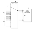
- the 10 Gbps transponder 3 a Upon receiving notification of the failure related to the wavelength ⁇ 1 , the 10 Gbps transponder 3 a stops the client signal 1 a input via the optical coupler 2 a using software or hardware by a control unit (not shown) provided therein. Further, upon receiving a notification of the failure relating to the wavelength ⁇ 1 , the switch control unit (provided in the M: N switch 40, not shown) controls switch switching of the M: N switch 40. Under the control of the switch control unit, the M: N switch 40 selects the client signal 1a from the client signals 1a to 1c input via the optical couplers 2a to 2c and outputs the selected client signal 1a as the redundant client signal 60. . At this time, the switch is switched to connect to the lowest numbered port (client interface) of the redundant 100 Gbps transponder 50. A signal flow in the M: N switch 40 at this time is shown in FIG.
- the redundant 100 Gbps transponder 50 transmits the redundant client signal 60 (substantially client signal 1a) input from the M: N switch 40 to the line side as a redundant WDM line signal 70 of 100 Gbps at the wavelength ⁇ 4 . Output. In this way, redundancy of wavelength ⁇ 1 is performed.
- the M: N switch 40 In addition to the wavelength ⁇ 1 , if any failure occurs on the path related to the wavelength ⁇ 2 of 40 Gbps, the M: N switch 40 has not yet occupied the client signal 1 b input via the optical coupler 2 b. It connects to the lowest numbered port among the ports of the redundant 100 Gbps transponder 50.
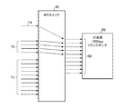
- a signal flow in the M: N switch 40 at this time is shown in FIG. FIG. 3 also shows the flow of signals in the M: N switch 40 when failures related to the wavelengths ⁇ 1 and ⁇ 2 occur simultaneously.
- the redundant 100 Gbps transponder 50 transmits the redundant client signal 60 (substantially the client signal 1a and the client signal 1b) input from the M: N switch 40 to the line side as a redundant WDM line signal 70 of 100 Gbps.
- the client signal placed on the wavelength where the failure has occurred Is output as a redundant WDM line signal 70 by the redundant 100 Gbps transponder 50. That is, the 10 Gbps transponder 3a, 40 Gbps transponder 3b, and 100 Gbps transponder 3c are the active system, and the redundant 100 Gbps transponder 50 is the redundant system.
- the optical couplers 2a to 2c, the M: N switch 40, and the redundant 100 Gbps transponder 50 constitute a wavelength redundant device, and are installed for redundancy even when different WDM transmission rates of 10 Gbps, 40 Gbps, and 100 Gbps are mixed. Only the redundant 100 Gbps transponder 50 is required for the transponder, and the bandwidth reserved for redundancy is also only required for the redundant 100 Gbps transponder 50. Therefore, the band can be used more effectively than when each wavelength redundancy device is installed for each WDM transmission rate. In addition, since it is not necessary to install a wavelength redundancy device for each WDM transmission rate, it is possible to reduce the cost and installation space required for the wavelength redundancy device.
- M For the client signal that has been switched to the output to the line side from the redundant 100 Gbps transponder 50 due to the occurrence of the failure, when the failure is resolved and returned to the output from the active system to the line side, M: When the connection from the N switch 40 to the port of the redundant 100 Gbps transponder 50 is rearranged to a port with a lower number, an outage is generated, so that the rearrangement is not performed. For example, when the client signal 1a occupying the lowest numbered port as shown in FIG. 3 is returned to the output from the active system to the line side, the lowest of the redundant 100 Gbps transponder 50 from the M: N switch 40 Although there is a vacancy in the connection to the numbered port (indicated by a broken line in FIG. 4), the connection destination port of the client signal 1b is left unchanged as shown in FIG.
- 10 Gbps transponders 3a having different output wavelengths are a (a is an integer of 1 or more), 40 Gbps transponders 3b are b (b is an integer of 1 or more), and 100 Gbps transponder 3c is c (Where c is an integer equal to or greater than 1), a 10 Gbps transponder 3a as a whole and a 10 Gbps base client interface as 1 ⁇ a, a b 40 Gbps transponder 3b as a whole and a 10 Gbps base client interface as 4 ⁇ b and c
- the entire 100 Gbps transponder 3c can have only 10 ⁇ c 10 Gbps-based client interfaces.
- the client signals 1a in FIG. 5 are transmitted in total of 1 ⁇ a in correspondence with the a 10 Gbps transponders 3a. Similarly, a total of 4 ⁇ b client signals 1b are transmitted corresponding to the b 40 Gbps transponders 3b. A total of 10 ⁇ c client signals 1c are transmitted corresponding to the c 100 Gbps transponders 3c.
- the M: N switch 41 is a (1 ⁇ a + 4 ⁇ b + 10 ⁇ c): 10 switch, selects a client signal mounted on a wavelength where a failure has occurred, and supplies it as a redundant client signal 60 to the redundant 100 Gbps transponder 50. By outputting, redundant processing is possible as in the configuration shown in FIG. Thus, even when there are a 10 Gbps transponders 3a, b 40 Gbps transponders 3b, and c 100 Gbps transponders 3c, the redundant transponder can be handled by one 100 Gbps transponder 50.
- the redundant 100 Gbps transponder 50 having a client interface adapted to the client signals 1a to 1c is provided.
- the M: N switch 40 or the M: N switch 41 selectively outputs redundant client signals 1a to 1c, thereby performing wavelength redundancy. Therefore, it is not necessary to install a wavelength redundancy device for each WDM transmission speed, and it is possible to effectively use a band and reduce the cost and installation space required for the wavelength redundancy device.
- the M: N switches 40 and 41 selectively output the client signal according to the priority of the client signal. Therefore, it is possible to ensure redundancy of important client signals.
- the M: N switch 40 and the M: N switch 41 are not limited to the 15:10 switch and (1 ⁇ a + 4 ⁇ b + 10 ⁇ c): 10 switch described above, but the number of client signals 1a to 1c, Depending on the configuration, the switch may be configured as a switch of K (K is an integer of 2 or more): L (L is an integer of 1 or more).
- FIG. FIG. 6 shows a configuration example of a terminal station apparatus provided with a wavelength redundancy apparatus according to Embodiment 2 of the present invention.
- redundancy is shown when different WDM transmission rates are mixed and the transmission rate of the client signal is the same.
- different WDM transmission rates are mixed and the transmission rate of the client signal is also the same. Redundancy is shown when multiple types are mixed.
- the terminal equipment includes optical couplers 2d and 2e for branching client signals 1d and 1e transmitted from the backhaul side, and d (d is an integer of 1 or more) 10 Gbps each including one 10 Gbps-based client interface.
- Transponder 3d (working transponder), e (e is an integer of 1 or more) 100 Gbps transponders 3e (working transponders) each having one 100 Gbps-based client interface, and M for selectively outputting input signals
- the client signal 1d is a 10 Gbps signal, corresponds to each of the d 10 Gbps transponders 3d, and is transmitted in a total of 1 ⁇ d.
- the client signal 1e is a 100 Gbps signal and corresponds to each of the e 100 Gbps transponders 3e, and a total of 1 ⁇ e is transmitted.
- the client signal 1d is branched by the optical coupler 2d in the 10 Gbps transponder 3d direction and the M: N switch 42 direction.
- the client signal 1e is branched by the optical coupler 2e into the 100 Gbps transponder 3e direction and the N: 1 switch 43 direction.
- the one directed to the M: N switch 42 or the N: 1 switch 43 is branched as a redundant client signal.
- the signal going to the M: N switch 42 or the N: 1 switch 43 and the signal going to the 10 Gbps transponder 3d or 100 Gbps transponder 3e are substantially the same signal, so both are described as client signals 1d and 1e. explain.
- the d 10 Gbps transponders 3d output the client signals 1d respectively input via the optical coupler 2d to the line side as 10 Gbps WDM line signals 4d at different wavelengths ⁇ 11 to ⁇ 1d .
- the e 100 Gbps transponders 3e output the client signals 1e respectively input via the optical coupler 2e to the line side as 100 Gbps WDM line signals 4e with different wavelengths ⁇ 31 to ⁇ 3e .
- the M: N switch 42 includes 1 ⁇ d 10 Gbps-based client interfaces, which is the same as the total number of client signals 1 d, and selectively receives the client signal 1 d input through the optical coupler 2 d as a redundant client signal 61. Output a maximum of 10 lines. That is, the M: N switch 42 is a d: 10 switch.
- the muxponder 80 bundles the redundant client signals 61 input from the M: N switch 42 and outputs them as a redundant client signal 62 of 100 Gbps.
- the N: 1 switch 43 includes 1 + 1 ⁇ e 100 Gbps-based client interfaces for the redundant client signal 62 input from the muxponder 80 and the client signal 1e input via the optical coupler 2e.
- the N: 1 switch 43 selectively outputs the input redundancy client signal 62 and the client signal 1 e as the redundancy client signal 63. That is, the N: 1 switch 43 is an e + 1: 1 switch.
- the redundant 100 Gbps transponder 51 outputs the redundant client signal 63 input from the N: 1 switch 43 via its own client interface to the line side as the redundant WDM line signal 71 of 100 Gbps at the wavelength ⁇ 41 . .
- the d 10 Gbps transponders 3d output the client signals 1d respectively input via the optical coupler 2d to the line side as 10 Gbps WDM line signals 4d at different wavelengths ⁇ 11 to ⁇ 1d .
- the e 100 Gbps transponders 3e output the client signal 1e input via the optical coupler 2e to the line side as a 100 Gbps WDM line signal 4e with different wavelengths ⁇ 31 to ⁇ 3e , respectively.
- processing such as wavelength multiplexing and amplification is performed and output to the optical transmission line.
- a wavelength division multiplexing optical transmission system is constructed with a plurality of terminal devices facing each other.
- a failure occurs on a path related to 10 or less wavelengths among the wavelengths ⁇ 11 to ⁇ 1d of the 10 Gbps WDM line signal 4d output by the d 10 Gbps transponders 3d, and this is notified to the terminal device.
- a failure occurs on a path related to 10 or less wavelengths among the wavelengths ⁇ 11 to ⁇ 1d of the 10 Gbps WDM line signal 4d output by the d 10 Gbps transponders 3d, and this is notified to the terminal device.
- the 10 Gbps transponder 3d that has received the notification of the failure related to the wavelength and outputs the wavelength at which the failure has occurred receives the client signal 1d input via the optical coupler 2d by software or hardware by a control unit (not shown) included in itself. Stop using the wear. Further, upon receiving a notification of a failure relating to the wavelength, the switch control unit (not shown) controls switch switching of the M: N switch 42 and the N: 1 switch 43. Under the control of the switch control unit, the M: N switch 42 is a client signal 1d that is input via the optical coupler 2d and that is output from the 10 Gbps transponder 3d on the wavelength at which the failure has occurred. 1d is selected and output as a redundant client signal 61.
- the muxponder 80 bundles the redundant client signals 61 (substantially the client signal 1d) input from the M: N switch 42 and outputs the bundled redundant client signals 62 of 100 Gbps.
- the N: 1 switch 43 is controlled by the switch control unit to select and output the redundant client signal 62 input from the muxponder 80 as the redundant client signal 63.
- the redundancy 100 Gbps transponder 51 outputs the redundancy client signal 63 input from the N: 1 switch 43 to the line side as a 100 Gbps redundancy WDM line signal 71 at a wavelength ⁇ 41 . Thereby, it is possible to make redundant a plurality of wavelengths of 10 or less in which a failure has occurred at the same time.
- the N: 1 switch 43 uses the client signal 1e that is input via the optical coupler 2e and that is output from the 100 Gbps transponder 3e on the wavelength where the failure has occurred, for redundancy.
- the client signal 63 is selected and output.
- the redundant 100 Gbps transponder 51 converts the redundant client signal 63 (substantially client signal 1e) input from the N: 1 switch 43 to the line side as a redundant WDM line signal 71 of 100 Gbps at the wavelength ⁇ 41 . Output.
- the wavelengths ⁇ 31 to ⁇ 3e where the failure has occurred can be made redundant.
- the d 10 Gbps transponders 3d, the e 100 Gbps transponders 3e function as the active system
- the redundant 100 Gbps transponder 51 functions as the redundant transponder.
- the M: N switch 42, the N: 1 switch 43, and the muxponder 80 constitute a selection switching unit, and the selection switching unit, the optical couplers 2d and 2e, and the redundancy 100 Gbps transponder 51 constitute a wavelength redundancy device. Yes. Even if different WDM transmission speeds of 10 Gbps and 100 Gbps are mixed, the redundant transponder is only required for the redundant 100 Gbps transponder 51, and the bandwidth reserved for the redundant is only required for the redundant 100 Gbps transponder 51.
- the band can be used more effectively than when each wavelength redundancy device is installed for each WDM transmission rate.
- it is not necessary to install a wavelength redundancy device for each WDM transmission rate, it is possible to reduce the cost and installation space required for the wavelength redundancy device.
- the M: N switch 42 and the N: 1 switch 43 are preliminarily set by, for example, setting the order of redundant client signals 1d and 1e. May be controlled by the switch control unit so as to selectively output the client signal according to the priority order.
- FIG. 6 shows a configuration in which d 10 Gbps transponders 3d to which 10 Gbps client signals 1d are respectively input and e 100 Gbps transponders 3e to which 100 Gbps client signals 1e are respectively input are mixed.
- FIGS. 7 and 8 show a configuration in which f (f is an integer of 1 or more) 40 Gbps transponders 3f (active transponders) to which 40 Gbps client signals 1f are respectively input are also present.
- Each of the f 40 Gbps transponders 3f has one 40 Gbps-based client interface, and the client signal 1f input via the optical coupler 2f is different to the line side as a 40 Gbps WDM line signal 4f.
- Output at wavelengths ⁇ 21 to ⁇ 2f are examples of the client signal 1f input via the optical coupler 2f .
- an optical coupler 2f corresponding to a path from the optical coupler 2d in FIG. 6 to the M: N switch 42, the muxponder 80, and the N: 1 switch 43 is simply used.
- a route connecting from the M: N switch 44, the Muxponder 81, and the N: 1 switch 43 may be added.
- the M: N switch 44 has 1 ⁇ f client interfaces based on 40 Gbps, which is the same as the total number of client signals 1f, and selectively uses the client signal 1f input via the optical coupler 2f as a redundant client signal 64. Output.
- the muxponder 81 bundles the redundant client signals 64 (substantially the client signal 1 f) input from the M: N switch 44 and outputs the bundled redundant client signals 65 of 100 Gbps.
- the N: 1 switch 43 receives a redundant client signal 65 input from the muxponder 81 in addition to the redundant client signal 62 input from the muxponder 80 and the client signal 1e input through the optical coupler 2e.
- the redundant client signal 63 is selectively output.
- the N: 1 switch 43 in FIG. 7 is an e + 2: 1 switch including 1 + 1 ⁇ e + 1 100 Gbps-based client interfaces.
- the redundant 100 Gbps transponder 51 outputs the redundant client signal 63 input from the N: 1 switch 43 via its own client interface to the line side as the redundant WDM line signal 71 of 100 Gbps at the wavelength ⁇ 41 . .
- the M: N switches 42 and 44, the N: 1 switch 43, and the muxponders 80 and 81 constitute a selection switching unit, the selection switching unit, the optical couplers 2d to 2f, and the redundant 100 Gbps transponder. 51 constitutes a wavelength redundancy device.
- FIG. 8 shows d 10 Gbps transponders 3d to which 10 Gbps client signals 1d are input, e 100 Gbps transponders 3e to which 100 Gbps client signals 1e are input, and 40 Gbps client signals 1f, respectively.
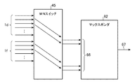
- the M: N switch 45 has a total of d + f client interfaces, d for the client signal 1d, f for the client signal 1f, and a maximum of two of the client signals 1d input through the optical coupler 2d. A maximum of two of the client signals 1 f input through the optical coupler 2 f are selectively output as redundant client signals 66.
- the muxponder 82 includes two 10 Gbps-based client interfaces and two 40 Gbps-based client interfaces, and a redundant client signal 66 (substantially a maximum of two clients) input from the M: N switch 42.
- the signal 1d and a maximum of two client signals 1f) are bundled and output as a redundant client signal 67 of 100 Gbps.
- the M: N switch 45, the N: 1 switch 43, and the muxponder 82 constitute a selection switching unit, and the selection switching unit, the optical couplers 2d to 2f, and the redundancy 100 Gbps transponder 51 are wavelength redundant. Configure the device.
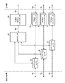
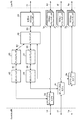
- FIG. 9 shows a signal flow in the M: N switch 45 together with the muxponder 82 when the redundancy processing is performed.
- the M: N switch 45 selects a maximum of two of the client signals 1d and 1f input via the optical couplers 2d and 2f and outputs the selected two as the redundant client signal 66.
- a redundant client signal 66 is newly output to the muxponder 82, the connection is made to the lowest numbered port among the available ports (client interfaces) of the muxponder 82, while FIG.
- the connection from the M: N switch 45 to the port of the muxponder 82 is not rearranged.
- the muxponder 82 has a transmission speed of an input signal of 100 Gbps or less and can output an output signal to a redundancy transponder (in FIG. 8, the redundancy is 100 Gbps).
- the configuration of its own client interface is changed according to the purpose, such as two 10 Gbps-based client interfaces and two 40 Gbps-based client interfaces. May be used.
- the configuration of the client interface of the muxponder 82 may be six 6 Gbps-based client interfaces and one 40 Gbps-based client interface.
- the M: N switch 45 selectively selects a maximum of six of the client signals 1d input via the optical coupler 2d and a maximum of one of the client signals 1f input via the optical coupler 2f. Are output as redundant client signals 66.
- the redundant 100 Gbps transponder 51 is shown as a constituent element, but instead of this, for example, it may be configured by a 400 Gbps transponder including four 100 Gbps-based client interfaces. .
- an M: N switch (M: 4 switch) is configured.
- M: N switch may be configured as a switch of K (K is an integer greater than or equal to 2): L (L is an integer greater than or equal to 1) depending on the configuration of the terminal device.
- the M: N switches 42, 44, and 45 are not limited to the above-described d: 10 switch and the like, but K (K is 2 depending on the number of client signals 1d to 1f and the configuration of the terminal device). It is also possible to configure as a switch of L (L is an integer equal to or greater than 1).
- the M: N switch and the N: 1 switch send the redundant client signals 1d to 1f.
- a muxponder that converts a signal that does not match the client interface of the redundant 100 Gbps transponder 51 into a signal of a transmission rate that matches the client interface is provided for wavelength redundancy. Therefore, it is not necessary to install a wavelength redundancy device for each WDM transmission speed, and it is possible to effectively use a band and reduce the cost and installation space required for the wavelength redundancy device.
- the M: N switch and the N: 1 switch selectively output the client signal according to the priority of the client signal. Therefore, it is possible to ensure redundancy of important client signals.
- the present invention it is possible to simultaneously protect a plurality of wavelengths within a range that can be accommodated by a transponder used as a redundant system. Therefore, the present invention is particularly effective in optical communication using a submarine cable in which failure is likely to occur at a plurality of wavelengths at the same time due to repeater output fluctuation, polarization hole burning, and the like.
- the transmission rate of each client signal and each WDM line signal is 10 Gbps, 40 Gbps, and 100 Gbps.
- the transmission rate of each client signal and each WDM line signal is not limited thereto. .
- the wavelength redundancy device and the wavelength redundancy method according to the present invention do not require the installation of each wavelength redundancy device for each WDM transmission speed, and effectively use the bandwidth, reduce the cost and installation space required for the wavelength redundancy device. Therefore, it is suitable for use in making a wavelength redundant in a wavelength division multiplexing optical transmission system.
Landscapes
- Engineering & Computer Science (AREA)
- Computer Networks & Wireless Communication (AREA)
- Signal Processing (AREA)
- Optical Communication System (AREA)
- Maintenance And Management Of Digital Transmission (AREA)
Abstract
Description
このような技術動向を受け、互いに異なる伝送速度を持つトランスポンダが混在した波長多重光伝送システムが、近年増えつつある。
実施の形態1.
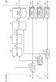
図1に、この発明の実施の形態1に係る波長冗長装置を備えた端局装置の構成例を示す。
端局装置は、バックホール側から伝送されるクライアント信号1a~1cを分岐するオプティカルカプラ2a~2cと、10Gbpsベースのクライアントインタフェースを1個備えた10Gbpsトランスポンダ3a(現用トランスポンダ)と、10Gbpsベースのクライアントインタフェースを4個備えた40Gbpsトランスポンダ3b(現用トランスポンダ)と、10Gbpsベースのクライアントインタフェースを10個備えた100Gbpsトランスポンダ3c(現用トランスポンダ)と、入力された信号を選択的に出力するM:Nスイッチ40(選択切替部)と、10Gbpsベースのクライアントインタフェースを10個備えた冗長用100Gbpsトランスポンダ50とを備えている。なお、図1では、冗長化に関係する構成要素のみを図示し、波長多重化、増幅等の処理を行う要素は省略する。
オプティカルカプラ2a~2cにより2方向に分岐されるクライアント信号1a~1cのうち、M:Nスイッチ40へ向かうものは、冗長用のクライアント信号として分岐される。なお、M:Nスイッチ40へ向かうものも、10Gbpsトランスポンダ3a又は40Gbpsトランスポンダ3b又は100Gbpsトランスポンダ3cへ向かうものも、実質的に同じ信号であるので、両者ともクライアント信号1a~1cと記載して説明する。
つまり、図1に示すのは、WDMライン信号の伝送速度(WDM伝送速度)は異なる速度が混在し、クライアント信号の伝送速度は同一のものである。
正常時においては、10Gbpsトランスポンダ3aが、オプティカルカプラ2aを介して入力されるクライアント信号1aを、ライン側へ、10GbpsのWDMライン信号4aとして、波長λ1で出力する。同様に、40Gbpsトランスポンダ3bが、オプティカルカプラ2bを介して入力されるクライアント信号1bを、ライン側へ、40GbpsのWDMライン信号4bとして、波長λ2で出力し、100Gbpsトランスポンダ3cが、オプティカルカプラ2cを介して入力されるクライアント信号1cを、ライン側へ、100GbpsのWDMライン信号4cとして、波長λ3で出力する。そして、波長多重化、増幅等の処理が行われて、光伝送路へと出力される。
例えば、10Gbpsトランスポンダ3aが出力する10GbpsのWDMライン信号4aの波長λ1に関する経路上に、何らかの障害が発生したとする。
この障害は、例えば、対向する他の端局装置により検出されて、通知されるようにすればよい。または、端局装置を含む波長多重光伝送システム全体を管理する装置(不図示)等により検出され、端局装置へ通知されるようにしてもよい。
また、波長λ1に関する障害の通知を受け、スイッチ制御部(M:Nスイッチ40に備えられる。不図示)は、M:Nスイッチ40のスイッチ切替を制御する。
スイッチ制御部に制御されて、M:Nスイッチ40は、オプティカルカプラ2a~2cを介して入力されるクライアント信号1a~1cのうち、クライアント信号1aを選択して、冗長用クライアント信号60として出力する。このとき、冗長用100Gbpsトランスポンダ50の一番低い番号のポート(クライアントインタフェース)へ接続するようにスイッチを切替える。このときのM:Nスイッチ40内の信号の流れを、図2に示す。
冗長用100Gbpsトランスポンダ50は、M:Nスイッチ40から入力される冗長用クライアント信号60(実質的にはクライアント信号1aとクライアント信号1b)を、ライン側へ、100Gbpsの冗長用WDMライン信号70として、波長λ4で出力する。このように、複数の波長λ1,λ2を同時に冗長することが可能である。
なお、100Gbpsの波長λ3に関する経路上に何らかの障害が発生した場合も、上記波長λ1,λ2のときと同様の冗長処理を行う。
つまり、10Gbpsトランスポンダ3a、40Gbpsトランスポンダ3b、100Gbpsトランスポンダ3cが現用系、冗長用100Gbpsトランスポンダ50が冗長系となる。
例えば、図3のように一番低い番号のポートを占有しているクライアント信号1aを現用系からのライン側への出力へ戻すと、M:Nスイッチ40から冗長用100Gbpsトランスポンダ50の一番低い番号のポートへの接続に空きが出るが(図4に破線で示す)、図4のように、クライアント信号1bの接続先のポートは変更せずそのままとする。
M:Nスイッチ41は、(1×a+4×b+10×c):10スイッチであり、障害が発生した波長に載せられているクライアント信号を選択して冗長用クライアント信号60として冗長用100Gbpsトランスポンダ50に出力することにより、図1に示した構成と同様に、冗長処理が可能である。
このように、10Gbpsトランスポンダ3aがa枚、40Gbpsトランスポンダ3bがb枚、100Gbpsトランスポンダ3cがc枚ある場合でも、冗長用のトランスポンダは、100Gbpsトランスポンダ50の1枚で対応できる。
なお、図5において他図と同一又は相当の部分については同一の符号を付し、その説明を省略又は簡略化する。以降の図においても同様である。
図6に、この発明の実施の形態2に係る波長冗長装置を備えた端局装置の構成例を示す。
実施の形態1では、異なるWDM伝送速度が混在し、クライアント信号の伝送速度が同一の場合の冗長について示したが、実施の形態2では、異なるWDM伝送速度が混在し、クライアント信号の伝送速度も複数種類が混在している場合の冗長について示す。
オプティカルカプラ2d,2eにより2方向に分岐されるクライアント信号1d,1eのうち、M:Nスイッチ42又はN:1スイッチ43へ向かうものは、冗長用のクライアント信号として分岐される。なお、M:Nスイッチ42又はN:1スイッチ43へ向かうものも、10Gbpsトランスポンダ3d又は100Gbpsトランスポンダ3eへ向かうものも、実質的に同じ信号であるので、両者ともクライアント信号1d,1eと記載して説明する。
N:1スイッチ43は、マックスポンダ80から入力される冗長用クライアント信号62用とオプティカルカプラ2eを介して入力されるクライアント信号1e用に、100Gbpsベースのクライアントインタフェースを、1+1×e個備える。N:1スイッチ43は、入力される冗長用クライアント信号62とクライアント信号1eを、選択的に冗長用クライアント信号63として出力する。つまり、N:1スイッチ43は、e+1:1スイッチである。
正常時においては、d枚の10Gbpsトランスポンダ3dが、オプティカルカプラ2dを介してそれぞれ入力されるクライアント信号1dを、ライン側へ、10GbpsのWDMライン信号4dとして、それぞれ異なる波長λ11~λ1dで出力する。同様に、e枚の100Gbpsトランスポンダ3eが、オプティカルカプラ2eを介して入力されるクライアント信号1eを、ライン側へ、100GbpsのWDMライン信号4eとして、それぞれ異なる波長λ31~λ3eで出力する。そして、波長多重化、増幅等の処理が行われて、光伝送路へと出力される。
例えば、d枚の10Gbpsトランスポンダ3dが出力する10GbpsのWDMライン信号4dの波長λ11~λ1dのうち、10個以下の波長に関する経路上に何らかの障害が発生し、その旨が端局装置へ通知されたとする。
また、波長に関する障害の通知を受け、スイッチ制御部(不図示)は、M:Nスイッチ42、N:1スイッチ43のスイッチ切替を制御する。
スイッチ制御部に制御されて、M:Nスイッチ42は、オプティカルカプラ2dを介して入力されるクライアント信号1dであって、障害が発生した波長に載せられて10Gbpsトランスポンダ3dから出力されていたクライアント信号1dを選択して、冗長用クライアント信号61として出力する。
N:1スイッチ43は、スイッチ制御部に制御されて、マックスポンダ80から入力される冗長用クライアント信号62を冗長用クライアント信号63として選択して出力する。
冗長用100Gbpsトランスポンダ51は、N:1スイッチ43から入力される冗長用クライアント信号63を、ライン側へ、100Gbpsの冗長用WDMライン信号71として、波長λ41で出力する。これにより、障害が発生した10個以下の複数の波長を同時に冗長することができる。
この場合、N:1スイッチ43は、オプティカルカプラ2eを介して入力されるクライアント信号1eであって、障害が発生した波長に載せられて100Gbpsトランスポンダ3eから出力されているクライアント信号1eを、冗長用クライアント信号63として選択して出力する。
冗長用100Gbpsトランスポンダ51は、N:1スイッチ43から入力される冗長用クライアント信号63(実質的にはクライアント信号1e)を、ライン側へ、100Gbpsの冗長用WDMライン信号71として、波長λ41で出力する。これにより、障害が発生した波長λ31~λ3eを冗長することができる。
M:Nスイッチ42、N:1スイッチ43、マックスポンダ80が、選択切替部を構成しており、当該選択切替部、オプティカルカプラ2d,2e、冗長用100Gbpsトランスポンダ51が波長冗長装置を構成している。10Gbps、100Gbpsという異なるWDM伝送速度が混在していても、冗長用に設置するトランスポンダは冗長用100Gbpsトランスポンダ51だけで済み、冗長用に確保する帯域も、冗長用100Gbpsトランスポンダ51用だけで済む。従って、WDM伝送速度ごとに波長冗長装置をそれぞれ設置する場合よりも、帯域の有効活用が可能となる。また、WDM伝送速度ごとに波長冗長装置をそれぞれ設置する必要がないために、波長冗長装置に掛かるコスト及び設置スペースの削減が可能である。
M:Nスイッチ44は40Gbpsベースのクライアントインタフェースを、クライアント信号1fの合計本数と同じ1×f個備え、オプティカルカプラ2fを介して入力されるクライアント信号1fを、選択的に冗長用クライアント信号64として出力する。
N:1スイッチ43は、マックスポンダ80から入力される冗長用クライアント信号62と、オプティカルカプラ2eを介して入力されるクライアント信号1eに加え、マックスポンダ81から入力される冗長用クライアント信号65を、選択的に冗長用クライアント信号63として出力する。従って、図7におけるN:1スイッチ43は、100Gbpsベースのクライアントインタフェースを、1+1×e+1個備えた、e+2:1スイッチである。
冗長用100Gbpsトランスポンダ51は、N:1スイッチ43から自身のクライアントインタフェースを介して入力される冗長用クライアント信号63を、ライン側へ、100Gbpsの冗長用WDMライン信号71として、波長λ41で出力する。
マックスポンダ82は、10Gbpsベースのクライアントインタフェースを2個、40Gbpsベースのクライアントインタフェースを2個備えており、M:Nスイッチ42から入力される冗長用クライアント信号66(実質的には最大2本のクライアント信号1d及び最大2本のクライアント信号1f)を束ねて、100Gbpsの冗長用クライアント信号67として出力する。
図8においては、M:Nスイッチ45、N:1スイッチ43、マックスポンダ82が、選択切替部を構成しており、当該選択切替部、オプティカルカプラ2d~2f、冗長用100Gbpsトランスポンダ51が波長冗長装置を構成している。
なお、新たにマックスポンダ82へ冗長用クライアント信号66を出力するときは、マックスポンダ82の空いているポート(クライアントインタフェース)のうち、一番低い番号のポートへ接続するようにする一方、図4で説明したのと同様に、障害が解消し、再度現用系からのライン側への出力へ戻す際、M:Nスイッチ45からのマックスポンダ82のポートへの接続の並び替えは行わない。
Claims (5)
- 入力されるクライアント信号を処理する複数の現用トランスポンダによって互いに異なる波長のWDM(Wavelength Division Multiplex)ライン信号が出力され、前記WDMライン信号の伝送速度は複数種類が混在している波長多重光伝送システムにおける波長冗長装置であって、
前記現用トランスポンダへ前記クライアント信号を出力すると共に、前記クライアント信号を分岐させた冗長用クライアント信号を出力するオプティカルカプラと、
クライアントインタフェースを有し、前記クライアントインタフェースより入力される信号を処理して冗長用WDMライン信号として出力する冗長用トランスポンダと、
前記オプティカルカプラが出力する前記冗長用クライアント信号が入力され、前記冗長用トランスポンダの前記クライアントインタフェースに適合する伝送速度の信号を選択的に出力する選択切替部とを備え、
前記現用トランスポンダが出力する前記WDMライン信号の波長に障害が発生すると、前記選択切替部は、当該障害が発生した波長の前記WDMライン信号を出力する前記現用トランスポンダに入力される前記クライアント信号の前記冗長用クライアント信号を選択して、前記冗長用トランスポンダの前記クライアントインタフェースに適合する伝送速度の冗長用クライアント信号として出力し、前記冗長用トランスポンダは、前記選択切替部が出力する前記クライアントインタフェースに適合する伝送速度の冗長用クライアント信号を処理して前記冗長用WDMライン信号を出力することを特徴とする波長冗長装置。 - 前記クライアント信号の伝送速度は、全て同一であり、
前記冗長用トランスポンダの前記クライアントインタフェースは、前記クライアント信号の伝送速度に適合しており、
前記選択切替部は、前記オプティカルカプラが出力する前記冗長用クライアント信号を選択的に出力するM(Mは2以上の整数):N(Nは1以上の整数)スイッチで構成されることを特徴とする請求項1記載の波長冗長装置。 - 前記クライアント信号の伝送速度は、複数種類が混在しており、
前記選択切替部は、
前記オプティカルカプラが出力する前記冗長用クライアント信号のうち、前記冗長用トランスポンダの前記クライアントインタフェースに適合しない伝送速度の信号を選択的に出力する第1のM(Mは2以上の整数):N(Nは1以上の整数)スイッチと、
前記第1のM:Nスイッチが出力する前記冗長用クライアント信号を処理して、前記冗長用トランスポンダの前記クライアントインタフェースに適合する伝送速度の冗長用クライアント信号として出力するマックスポンダと、
前記オプティカルカプラが出力する前記冗長用クライアント信号のうち、前記冗長用トランスポンダの前記クライアントインタフェースに適合する伝送速度の信号、及び、前記マックスポンダが出力する前記冗長用トランスポンダの前記クライアントインタフェースに適合する伝送速度の冗長用クライアント信号を、前記冗長用トランスポンダへ選択的に出力する第2のM(Mは2以上の整数):N(Nは1以上の整数)スイッチとで構成されることを特徴とする請求項1記載の波長冗長装置。 - 前記選択切替部は、前記オプティカルカプラが出力する前記冗長用クライアント信号を優先度に応じて選択して出力することを特徴とする請求項1記載の波長冗長装置。
- 入力されるクライアント信号を処理する複数の現用トランスポンダによって互いに異なる波長のWDM(Wavelength Division Multiplex)ライン信号が出力され、前記WDMライン信号の伝送速度は複数種類が混在している波長多重光伝送システムにおいて、
前記現用トランスポンダへ前記クライアント信号を出力すると共に、前記クライアント信号を分岐させた冗長用クライアント信号を出力するオプティカルカプラと、
クライアントインタフェースを有し、前記クライアントインタフェースより入力される信号を処理して冗長用WDMライン信号として出力する冗長用トランスポンダと、
前記オプティカルカプラが出力する前記冗長用クライアント信号が入力され、前記冗長用トランスポンダの前記クライアントインタフェースに適合する伝送速度の信号を選択的に出力する選択切替部とを備える波長冗長装置の波長冗長方法であって、
前記現用トランスポンダが出力する前記WDMライン信号の波長に障害が発生すると、前記選択切替部が、当該障害が発生した波長の前記WDMライン信号を出力する前記現用トランスポンダに入力される前記クライアント信号の前記冗長用クライアント信号を選択する信号選択ステップと、
前記選択切替部が、前記信号選択ステップで選択した前記冗長用クライアント信号を、前記冗長用トランスポンダの前記クライアントインタフェースに適合する伝送速度の冗長用クライアント信号として出力する第1の信号出力ステップと、
前記冗長用トランスポンダが、前記第1の信号出力ステップで出力された前記クライアントインタフェースに適合する伝送速度の冗長用クライアント信号を処理して、前記冗長用WDMライン信号を出力する第2の信号出力ステップとを備えることを特徴とする波長冗長方法。
Priority Applications (4)
| Application Number | Priority Date | Filing Date | Title |
|---|---|---|---|
| US15/117,006 US9872090B2 (en) | 2014-02-25 | 2015-01-06 | Wavelength redundancy device and wavelength redundancy method |
| EP15754773.8A EP3113389B1 (en) | 2014-02-25 | 2015-01-06 | Wavelength redundancey device and wavelength redundancy method |
| JP2016505083A JP6109402B2 (ja) | 2014-02-25 | 2015-01-06 | 波長冗長装置及び波長冗長方法 |
| CN201580010195.0A CN106031054B (zh) | 2014-02-25 | 2015-01-06 | 波长冗余装置及波长冗余方法 |
Applications Claiming Priority (2)
| Application Number | Priority Date | Filing Date | Title |
|---|---|---|---|
| JP2014-034155 | 2014-02-25 | ||
| JP2014034155 | 2014-02-25 |
Publications (1)
| Publication Number | Publication Date |
|---|---|
| WO2015129290A1 true WO2015129290A1 (ja) | 2015-09-03 |
Family
ID=54008620
Family Applications (1)
| Application Number | Title | Priority Date | Filing Date |
|---|---|---|---|
| PCT/JP2015/050150 Ceased WO2015129290A1 (ja) | 2014-02-25 | 2015-01-06 | 波長冗長装置及び波長冗長方法 |
Country Status (5)
| Country | Link |
|---|---|
| US (1) | US9872090B2 (ja) |
| EP (1) | EP3113389B1 (ja) |
| JP (1) | JP6109402B2 (ja) |
| CN (1) | CN106031054B (ja) |
| WO (1) | WO2015129290A1 (ja) |
Families Citing this family (3)
| Publication number | Priority date | Publication date | Assignee | Title |
|---|---|---|---|---|
| US20190342027A1 (en) * | 2016-12-05 | 2019-11-07 | Nec Corporation | Optical transmission device and optical transmission method |
| US10908369B1 (en) * | 2017-06-26 | 2021-02-02 | Amazon Technologies, Inc. | Flexible onboard optics for networking switches |
| US10623090B2 (en) * | 2018-05-24 | 2020-04-14 | At&T Intellectual Property I, L.P. | Multi-lane optical transport network recovery |
Citations (2)
| Publication number | Priority date | Publication date | Assignee | Title |
|---|---|---|---|---|
| WO2012073419A1 (ja) * | 2010-11-29 | 2012-06-07 | 三菱電機株式会社 | 波長多重光伝送システム、送信装置および受信装置 |
| JP2012195782A (ja) * | 2011-03-16 | 2012-10-11 | Mitsubishi Electric Corp | 光ネットワークシステムおよびwdm装置 |
Family Cites Families (4)
| Publication number | Priority date | Publication date | Assignee | Title |
|---|---|---|---|---|
| JP2009130505A (ja) * | 2007-11-21 | 2009-06-11 | Fujitsu Ltd | 光伝送装置、光入力断検出閾値設定方法および光入力断検出閾値設定プログラム |
| EP2337230B1 (en) * | 2008-10-15 | 2019-01-09 | Mitsubishi Electric Corporation | Optical network system, optical redundant switching device, and wdm device |
| CN102342041B (zh) * | 2009-03-04 | 2014-09-03 | 三菱电机株式会社 | 光传输装置 |
| JP2013126193A (ja) | 2011-12-15 | 2013-06-24 | Nec Corp | 波長冗長装置及び方法並びにこれを用いた波長多重光伝送システム及び方法 |
-
2015
- 2015-01-06 WO PCT/JP2015/050150 patent/WO2015129290A1/ja not_active Ceased
- 2015-01-06 JP JP2016505083A patent/JP6109402B2/ja not_active Expired - Fee Related
- 2015-01-06 CN CN201580010195.0A patent/CN106031054B/zh not_active Expired - Fee Related
- 2015-01-06 EP EP15754773.8A patent/EP3113389B1/en active Active
- 2015-01-06 US US15/117,006 patent/US9872090B2/en not_active Expired - Fee Related
Patent Citations (2)
| Publication number | Priority date | Publication date | Assignee | Title |
|---|---|---|---|---|
| WO2012073419A1 (ja) * | 2010-11-29 | 2012-06-07 | 三菱電機株式会社 | 波長多重光伝送システム、送信装置および受信装置 |
| JP2012195782A (ja) * | 2011-03-16 | 2012-10-11 | Mitsubishi Electric Corp | 光ネットワークシステムおよびwdm装置 |
Also Published As
| Publication number | Publication date |
|---|---|
| US9872090B2 (en) | 2018-01-16 |
| JP6109402B2 (ja) | 2017-04-05 |
| US20170180834A1 (en) | 2017-06-22 |
| CN106031054B (zh) | 2019-03-29 |
| EP3113389A1 (en) | 2017-01-04 |
| CN106031054A (zh) | 2016-10-12 |
| EP3113389B1 (en) | 2019-09-25 |
| EP3113389A4 (en) | 2017-09-27 |
| JPWO2015129290A1 (ja) | 2017-03-30 |
Similar Documents
| Publication | Publication Date | Title |
|---|---|---|
| EP2938094B1 (en) | Data center network and method for deploying the data center network | |
| US11789209B2 (en) | Pair routing between undersea fiber optic cables | |
| JP7402585B2 (ja) | ファイバ対切替を有する海中ケーブル分岐ユニット及び光通信システム | |
| EP2493096B1 (en) | Method, system and device for single-fiber bidirectional ring network protection | |
| JP2008271603A (ja) | 光ネットワーク及びプロテクションスイッチング方法 | |
| WO2012132688A1 (ja) | 光伝送装置 | |
| US9762348B2 (en) | Reconfigurable optical add-drop multiplexer apparatus | |
| EP3582417B1 (en) | Intelligence- defined optical tunnel network system controller and control method thereof | |
| WO2023179785A1 (zh) | 光纤连接盒、数据处理方法、计算机存储介质 | |
| JP2013258530A (ja) | 双方向モニタモジュール、光モジュール及び光分岐挿入装置 | |
| US20040141741A1 (en) | Optical network protection switching architecture | |
| JP4899589B2 (ja) | 光ネットワーク、光ネットワークのプロテクション方法及びノード | |
| JP6109402B2 (ja) | 波長冗長装置及び波長冗長方法 | |
| CN100370700C (zh) | 波分复用系统中光通道共享保护的实现方法、系统及装置 | |
| JP6095652B2 (ja) | 対称光多重化ノード | |
| CN107819522B (zh) | Roadm设备、光网络系统以及传输方法 | |
| WO2020054614A1 (ja) | 経路切替装置および経路切替方法 | |
| JP5764989B2 (ja) | 光信号分岐装置、光信号分岐システム、および光信号分岐方法 | |
| WO2018142907A1 (ja) | 光パスネットワーク | |
| CN101399609B (zh) | 光分路系统和光分路方法 | |
| JP6253506B2 (ja) | 送信装置および光通信システム | |
| EP2234329A1 (en) | The method and device for protecting the shared channel in the optical transmission system | |
| WO2025094243A1 (ja) | 光通信システム、光通信装置及び光通信方法 | |
| KR20130093751A (ko) | Wdm 기반의 무선 광 전달망을 제공하기 위한 시스템 및 이를 이용한 무선 광 신호 전달 방법 | |
| KR101462433B1 (ko) | 무선 액세스 네트워크에서 회선을 재설정하기 위한 회선 재설정 시스템 및 그 방법 |
Legal Events
| Date | Code | Title | Description |
|---|---|---|---|
| 121 | Ep: the epo has been informed by wipo that ep was designated in this application |
Ref document number: 15754773 Country of ref document: EP Kind code of ref document: A1 |
|
| ENP | Entry into the national phase |
Ref document number: 2016505083 Country of ref document: JP Kind code of ref document: A |
|
| WWE | Wipo information: entry into national phase |
Ref document number: 15117006 Country of ref document: US |
|
| REEP | Request for entry into the european phase |
Ref document number: 2015754773 Country of ref document: EP |
|
| WWE | Wipo information: entry into national phase |
Ref document number: 2015754773 Country of ref document: EP |
|
| NENP | Non-entry into the national phase |
Ref country code: DE |