WO2015129303A1 - 液注出用プラスチック成形体 - Google Patents
液注出用プラスチック成形体 Download PDFInfo
- Publication number
- WO2015129303A1 WO2015129303A1 PCT/JP2015/050585 JP2015050585W WO2015129303A1 WO 2015129303 A1 WO2015129303 A1 WO 2015129303A1 JP 2015050585 W JP2015050585 W JP 2015050585W WO 2015129303 A1 WO2015129303 A1 WO 2015129303A1
- Authority
- WO
- WIPO (PCT)
- Prior art keywords
- liquid
- spout
- cap
- pouring
- flow path
- Prior art date
- Legal status (The legal status is an assumption and is not a legal conclusion. Google has not performed a legal analysis and makes no representation as to the accuracy of the status listed.)
- Ceased
Links
Images




Classifications
-
- B—PERFORMING OPERATIONS; TRANSPORTING
- B65—CONVEYING; PACKING; STORING; HANDLING THIN OR FILAMENTARY MATERIAL
- B65D—CONTAINERS FOR STORAGE OR TRANSPORT OF ARTICLES OR MATERIALS, e.g. BAGS, BARRELS, BOTTLES, BOXES, CANS, CARTONS, CRATES, DRUMS, JARS, TANKS, HOPPERS, FORWARDING CONTAINERS; ACCESSORIES, CLOSURES, OR FITTINGS THEREFOR; PACKAGING ELEMENTS; PACKAGES
- B65D25/00—Details of other kinds or types of rigid or semi-rigid containers
- B65D25/38—Devices for discharging contents
- B65D25/40—Nozzles or spouts
- B65D25/42—Integral or attached nozzles or spouts
-
- B—PERFORMING OPERATIONS; TRANSPORTING
- B65—CONVEYING; PACKING; STORING; HANDLING THIN OR FILAMENTARY MATERIAL
- B65D—CONTAINERS FOR STORAGE OR TRANSPORT OF ARTICLES OR MATERIALS, e.g. BAGS, BARRELS, BOTTLES, BOXES, CANS, CARTONS, CRATES, DRUMS, JARS, TANKS, HOPPERS, FORWARDING CONTAINERS; ACCESSORIES, CLOSURES, OR FITTINGS THEREFOR; PACKAGING ELEMENTS; PACKAGES
- B65D1/00—Rigid or semi-rigid containers having bodies formed in one piece, e.g. by casting metallic material, by moulding plastics, by blowing vitreous material, by throwing ceramic material, by moulding pulped fibrous material or by deep-drawing operations performed on sheet material
- B65D1/02—Bottles or similar containers with necks or like restricted apertures, designed for pouring contents
-
- B—PERFORMING OPERATIONS; TRANSPORTING
- B65—CONVEYING; PACKING; STORING; HANDLING THIN OR FILAMENTARY MATERIAL
- B65D—CONTAINERS FOR STORAGE OR TRANSPORT OF ARTICLES OR MATERIALS, e.g. BAGS, BARRELS, BOTTLES, BOXES, CANS, CARTONS, CRATES, DRUMS, JARS, TANKS, HOPPERS, FORWARDING CONTAINERS; ACCESSORIES, CLOSURES, OR FITTINGS THEREFOR; PACKAGING ELEMENTS; PACKAGES
- B65D23/00—Details of bottles or jars not otherwise provided for
- B65D23/02—Linings or internal coatings
-
- B—PERFORMING OPERATIONS; TRANSPORTING
- B65—CONVEYING; PACKING; STORING; HANDLING THIN OR FILAMENTARY MATERIAL
- B65D—CONTAINERS FOR STORAGE OR TRANSPORT OF ARTICLES OR MATERIALS, e.g. BAGS, BARRELS, BOTTLES, BOXES, CANS, CARTONS, CRATES, DRUMS, JARS, TANKS, HOPPERS, FORWARDING CONTAINERS; ACCESSORIES, CLOSURES, OR FITTINGS THEREFOR; PACKAGING ELEMENTS; PACKAGES
- B65D23/00—Details of bottles or jars not otherwise provided for
- B65D23/06—Integral drip catchers or drip-preventing means
-
- B—PERFORMING OPERATIONS; TRANSPORTING
- B65—CONVEYING; PACKING; STORING; HANDLING THIN OR FILAMENTARY MATERIAL
- B65D—CONTAINERS FOR STORAGE OR TRANSPORT OF ARTICLES OR MATERIALS, e.g. BAGS, BARRELS, BOTTLES, BOXES, CANS, CARTONS, CRATES, DRUMS, JARS, TANKS, HOPPERS, FORWARDING CONTAINERS; ACCESSORIES, CLOSURES, OR FITTINGS THEREFOR; PACKAGING ELEMENTS; PACKAGES
- B65D41/00—Caps, e.g. crown caps or crown seals, i.e. members having parts arranged for engagement with the external periphery of a neck or wall defining a pouring opening or discharge aperture; Protective cap-like covers for closure members, e.g. decorative covers of metal foil or paper
- B65D41/02—Caps or cap-like covers without lines of weakness, tearing strips, tags, or like opening or removal devices
- B65D41/04—Threaded or like caps or cap-like covers secured by rotation
- B65D41/0407—Threaded or like caps or cap-like covers secured by rotation with integral sealing means
- B65D41/0414—Threaded or like caps or cap-like covers secured by rotation with integral sealing means formed by a plug, collar, flange, rib or the like contacting the internal surface of a container neck
- B65D41/0421—Threaded or like caps or cap-like covers secured by rotation with integral sealing means formed by a plug, collar, flange, rib or the like contacting the internal surface of a container neck and combined with integral sealing means contacting other surfaces of a container neck
-
- B—PERFORMING OPERATIONS; TRANSPORTING
- B65—CONVEYING; PACKING; STORING; HANDLING THIN OR FILAMENTARY MATERIAL
- B65D—CONTAINERS FOR STORAGE OR TRANSPORT OF ARTICLES OR MATERIALS, e.g. BAGS, BARRELS, BOTTLES, BOXES, CANS, CARTONS, CRATES, DRUMS, JARS, TANKS, HOPPERS, FORWARDING CONTAINERS; ACCESSORIES, CLOSURES, OR FITTINGS THEREFOR; PACKAGING ELEMENTS; PACKAGES
- B65D47/00—Closures with filling and discharging, or with discharging, devices
- B65D47/04—Closures with discharging devices other than pumps
- B65D47/06—Closures with discharging devices other than pumps with pouring spouts or tubes; with discharge nozzles or passages
-
- B—PERFORMING OPERATIONS; TRANSPORTING
- B65—CONVEYING; PACKING; STORING; HANDLING THIN OR FILAMENTARY MATERIAL
- B65D—CONTAINERS FOR STORAGE OR TRANSPORT OF ARTICLES OR MATERIALS, e.g. BAGS, BARRELS, BOTTLES, BOXES, CANS, CARTONS, CRATES, DRUMS, JARS, TANKS, HOPPERS, FORWARDING CONTAINERS; ACCESSORIES, CLOSURES, OR FITTINGS THEREFOR; PACKAGING ELEMENTS; PACKAGES
- B65D47/00—Closures with filling and discharging, or with discharging, devices
- B65D47/04—Closures with discharging devices other than pumps
- B65D47/06—Closures with discharging devices other than pumps with pouring spouts or tubes; with discharge nozzles or passages
- B65D47/08—Closures with discharging devices other than pumps with pouring spouts or tubes; with discharge nozzles or passages having articulated or hinged closures
- B65D47/0804—Closures with discharging devices other than pumps with pouring spouts or tubes; with discharge nozzles or passages having articulated or hinged closures integrally formed with the base element provided with the spout or discharge passage
- B65D47/0809—Closures with discharging devices other than pumps with pouring spouts or tubes; with discharge nozzles or passages having articulated or hinged closures integrally formed with the base element provided with the spout or discharge passage and elastically biased towards both the open and the closed positions
-
- B—PERFORMING OPERATIONS; TRANSPORTING
- B65—CONVEYING; PACKING; STORING; HANDLING THIN OR FILAMENTARY MATERIAL
- B65D—CONTAINERS FOR STORAGE OR TRANSPORT OF ARTICLES OR MATERIALS, e.g. BAGS, BARRELS, BOTTLES, BOXES, CANS, CARTONS, CRATES, DRUMS, JARS, TANKS, HOPPERS, FORWARDING CONTAINERS; ACCESSORIES, CLOSURES, OR FITTINGS THEREFOR; PACKAGING ELEMENTS; PACKAGES
- B65D47/00—Closures with filling and discharging, or with discharging, devices
- B65D47/40—Closures with filling and discharging, or with discharging, devices with drip catchers or drip-preventing means
-
- B—PERFORMING OPERATIONS; TRANSPORTING
- B65—CONVEYING; PACKING; STORING; HANDLING THIN OR FILAMENTARY MATERIAL
- B65D—CONTAINERS FOR STORAGE OR TRANSPORT OF ARTICLES OR MATERIALS, e.g. BAGS, BARRELS, BOTTLES, BOXES, CANS, CARTONS, CRATES, DRUMS, JARS, TANKS, HOPPERS, FORWARDING CONTAINERS; ACCESSORIES, CLOSURES, OR FITTINGS THEREFOR; PACKAGING ELEMENTS; PACKAGES
- B65D5/00—Rigid or semi-rigid containers of polygonal cross-section, e.g. boxes, cartons or trays, formed by folding or erecting one or more blanks made of paper
- B65D5/42—Details of containers or of foldable or erectable container blanks
- B65D5/72—Contents-dispensing means
- B65D5/74—Spouts
- B65D5/746—Spouts formed separately from the container
-
- B—PERFORMING OPERATIONS; TRANSPORTING
- B65—CONVEYING; PACKING; STORING; HANDLING THIN OR FILAMENTARY MATERIAL
- B65D—CONTAINERS FOR STORAGE OR TRANSPORT OF ARTICLES OR MATERIALS, e.g. BAGS, BARRELS, BOTTLES, BOXES, CANS, CARTONS, CRATES, DRUMS, JARS, TANKS, HOPPERS, FORWARDING CONTAINERS; ACCESSORIES, CLOSURES, OR FITTINGS THEREFOR; PACKAGING ELEMENTS; PACKAGES
- B65D75/00—Packages comprising articles or materials partially or wholly enclosed in strips, sheets, blanks, tubes or webs of flexible sheet material, e.g. in folded wrappers
- B65D75/52—Details
- B65D75/58—Opening or contents-removing devices added or incorporated during package manufacture
- B65D75/5861—Spouts
- B65D75/5866—Integral spouts
-
- B—PERFORMING OPERATIONS; TRANSPORTING
- B65—CONVEYING; PACKING; STORING; HANDLING THIN OR FILAMENTARY MATERIAL
- B65D—CONTAINERS FOR STORAGE OR TRANSPORT OF ARTICLES OR MATERIALS, e.g. BAGS, BARRELS, BOTTLES, BOXES, CANS, CARTONS, CRATES, DRUMS, JARS, TANKS, HOPPERS, FORWARDING CONTAINERS; ACCESSORIES, CLOSURES, OR FITTINGS THEREFOR; PACKAGING ELEMENTS; PACKAGES
- B65D75/00—Packages comprising articles or materials partially or wholly enclosed in strips, sheets, blanks, tubes or webs of flexible sheet material, e.g. in folded wrappers
- B65D75/52—Details
- B65D75/58—Opening or contents-removing devices added or incorporated during package manufacture
- B65D75/5861—Spouts
- B65D75/5872—Non-integral spouts
-
- B—PERFORMING OPERATIONS; TRANSPORTING
- B65—CONVEYING; PACKING; STORING; HANDLING THIN OR FILAMENTARY MATERIAL
- B65D—CONTAINERS FOR STORAGE OR TRANSPORT OF ARTICLES OR MATERIALS, e.g. BAGS, BARRELS, BOTTLES, BOXES, CANS, CARTONS, CRATES, DRUMS, JARS, TANKS, HOPPERS, FORWARDING CONTAINERS; ACCESSORIES, CLOSURES, OR FITTINGS THEREFOR; PACKAGING ELEMENTS; PACKAGES
- B65D2401/00—Tamper-indicating means
- B65D2401/15—Tearable part of the closure
- B65D2401/25—Non-metallic tear-off strips
-
- B—PERFORMING OPERATIONS; TRANSPORTING
- B65—CONVEYING; PACKING; STORING; HANDLING THIN OR FILAMENTARY MATERIAL
- B65D—CONTAINERS FOR STORAGE OR TRANSPORT OF ARTICLES OR MATERIALS, e.g. BAGS, BARRELS, BOTTLES, BOXES, CANS, CARTONS, CRATES, DRUMS, JARS, TANKS, HOPPERS, FORWARDING CONTAINERS; ACCESSORIES, CLOSURES, OR FITTINGS THEREFOR; PACKAGING ELEMENTS; PACKAGES
- B65D2547/00—Closures with filling and discharging, or with discharging, devices
- B65D2547/04—Closures with discharging devices other than pumps
- B65D2547/06—Closures with discharging devices other than pumps with pouring spouts ot tubes; with discharge nozzles or passages
- B65D2547/063—Details of spouts
- B65D2547/066—Details of spouts inserted in or attached to the base element
-
- B—PERFORMING OPERATIONS; TRANSPORTING
- B65—CONVEYING; PACKING; STORING; HANDLING THIN OR FILAMENTARY MATERIAL
- B65D—CONTAINERS FOR STORAGE OR TRANSPORT OF ARTICLES OR MATERIALS, e.g. BAGS, BARRELS, BOTTLES, BOXES, CANS, CARTONS, CRATES, DRUMS, JARS, TANKS, HOPPERS, FORWARDING CONTAINERS; ACCESSORIES, CLOSURES, OR FITTINGS THEREFOR; PACKAGING ELEMENTS; PACKAGES
- B65D75/00—Packages comprising articles or materials partially or wholly enclosed in strips, sheets, blanks, tubes or webs of flexible sheet material, e.g. in folded wrappers
- B65D75/52—Details
- B65D75/58—Opening or contents-removing devices added or incorporated during package manufacture
- B65D75/5861—Spouts
- B65D75/5872—Non-integral spouts
- B65D75/5883—Non-integral spouts connected to the package at the sealed junction of two package walls
Definitions
- the present invention relates to a plastic molding for liquid pouring provided with a channel surface when a liquid showing high wettability with respect to plastic such as oily liquid is poured out.
- plastics are easier to mold than glass and metal, and can be easily molded into various shapes, so that they are used in various applications.
- the field of packaging such as a container such as a bottle and a cap attached to the container is a typical field of plastic use.
- Patent Document 1 proposes a method of coating the spout with a fluororesin or the like. A rough surface technique has been proposed.
- the conventionally known dripping prevention means proposed in the prior art as described above can sufficiently prevent liquid dripping with respect to the aqueous content liquid and effectively prevent dripping from the spout. It is possible to prevent dripping of highly wettable liquids that exhibit high wettability to plastics, such as edible oils, liquid detergents containing surfactants, and alcoholic beverages containing high concentrations of alcohol. In particular, the technique of applying a rough surface to the spout has a problem that the dripping property is rather increased.
- an object of the present invention is to provide a spout when a high wettability liquid exhibiting high wettability with respect to plastic is poured out, and effectively prevent dripping of the high wettability fluid from the spout.
- An object of the present invention is to provide a molded plastic product.
- a fluororesin coating is applied to at least one of the surface that becomes a liquid flow path when liquid dripping occurs at the spout and the surface that becomes a liquid flow path when liquid is poured out, and the fluororesin coating
- the surface of the surface has an arithmetic average roughness (Ra) in the surface roughness measurement in the range of 0.4 to 200 ⁇ m and is defined as an average height (Rc) / element average length (RSm) in the linear roughness measurement.
- Ra arithmetic average roughness
- Rc average height
- RSm element average length
- the base surface on which the fluororesin coating is applied is a rough surface having the arithmetic average roughness (Ra) and the element average height (Rh), and the rough surface is the surface of the fluororesin coating.
- the high wettability liquid is a liquid having a contact angle to the polyolefin resin of 40 degrees or less, Is preferred.
- the plastic molded body of the present invention is (3) At least the surface of the spout is formed of a polyolefin resin, (4) A spout to be attached to a bag-like container or a paper container, (5) A cap that is attached to the container mouth, and the cap includes a pouring nozzle having the pouring spout when pouring out the highly wettable liquid contained in the container. Or (6) It is a bottle, and the spout is formed at the mouth of the bottle. It can take the form.
- the plastic molded body of the present invention has a portion serving as a spout when the liquid contained in the container is poured out, and is particularly suitable for pouring out a highly wettable liquid exhibiting high wettability with respect to plastic.
- the spout portion is provided with a fluororesin coating, and the surface of the fluororesin coating has a certain range of arithmetic average roughness (Ra) and element average height (Rh). It has a rough surface. That is, in the present invention, the fluororesin coating improves the liquid repellency with respect to a highly wettable liquid (that is, increases the contact angle), and the coating surface becomes a rough surface that satisfies certain conditions.
- the slipperiness of the surface with respect to the liquid is remarkably improved.
- the liquid breakage is remarkably improved, and the liquid exhibits high wettability with respect to the plastic, For example, it is possible to effectively prevent dripping when edible oil or the like is poured out.
- the schematic half sectional view which shows the form of the pouring spout which produces dripping.
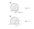
- the schematic diagram which shows the contact pattern of the droplet in a spout in Cassie mode and Wenzel mode.
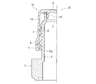
- the half cross section side view which shows the structure of the spout which is one form of the plastic molding of this invention.
- the half sectional view which shows the spout of FIG. 3 with a cover body.
- the perspective view which shows the structure of the cap for paper containers which is one form of the plastic molding of this invention.
- Sectional drawing which shows the structure of the cap for extraction which is one form of the plastic molding of this invention.
- this plastic molded body has a spout nozzle 150 having a spout 110 at the tip thereof.
- the liquid flow path 200 is formed by 150, and the nozzle 150 is tilted, whereby a predetermined liquid is poured out from the spout 110.
- the pouring spout 110 is formed of a surface (upper surface) 110a that becomes a liquid flow path at the time of liquid pouring and a surface (back surface) 110b that becomes a liquid dripping flow path when liquid dripping occurs.
- the spout 110 may be formed in a straight shape, but generally, the spout 110 is formed in an outwardly convex shape so that the liquid to be poured does not flow down along the outer surface of the nozzle 150. It has a curved shape extending toward the direction.
- the plastic molded body of the present invention provided with such a pouring nozzle 150 may be formed of a known plastic that can be molded into a predetermined shape, and is formed of an appropriate thermoplastic resin depending on the application. .
- a polyolefin resin such as polyethylene or polypropylene
- PET polyethylene terephthalate
- the liquid poured out from the above-mentioned pouring nozzle 150 has a high wettability with respect to plastic, and specifically has a contact angle of 40 degrees or less with respect to a polyolefin resin (particularly polypropylene). Yes, such a contact angle is measured by dropping the liquid onto a smooth surface (arithmetic average roughness (Ra) of 0.1 ⁇ m or less) of the polypropylene substrate.
- a contact angle is measured by dropping the liquid onto a smooth surface (arithmetic average roughness (Ra) of 0.1 ⁇ m or less) of the polypropylene substrate.
- such high wettability liquids include various edible oils, liquids containing surfactants, dressings, and alcoholic beverages containing high-concentration alcohol.
- the pouring spout 110 is coated with a fluororesin. That is, when liquid dripping occurs when the liquid is poured by tilting the pouring nozzle 150, fluorine is applied to the back surface 110b of the spout 110 serving as a liquid dripping flow path and to the upper surface 110a serving as a liquid flow path during liquid pouring. A resin coating is applied, which improves the liquid repellency of the wettable liquid poured out. As the fluororesin used for such coating, those known per se can be used.
- polytetrafluoroethylene PTFE
- polychlorotrifluoroethylene PCTFE
- polyvinylidene fluoride PVDF
- polyvinyl fluoride PVDF
- perfluoroalkoxy fluororesin PFA
- FEP ethylene / tetrafluoroethylene copolymer
- ETFE ethylene / chlorotrifluoroethylene copolymer
- ECTFE chlorotrifluoroethylene copolymer
- a coating solution is prepared by dissolving the resin in an appropriate low boiling point organic solvent (for example, hydrofluoroether, ethanol, etc.), and this is applied to the spout 110 described above. It can be easily formed by coating and drying.
- an appropriate low boiling point organic solvent for example, hydrofluoroether, ethanol, etc.
- the thickness of the fluororesin coating formed is usually about 10 nm to 1000 nm. If this thickness is too thin, the variation in thickness increases, and it may be difficult to effectively impart liquid repellency. Further, if this thickness is too thick, the effect of preventing dripping cannot be further increased, but rather the cost is increased, and further, roughening performed by the method described later may be difficult. . That is, the rough surface formed on the mold may not be reflected on the surface of the fluororesin coating. In order to increase the adhesive strength between the fluororesin coating and the plastic, acrylic resin, acid-modified polyolefin resin, or the like may be coated as a base.
- the surface of the fluororesin coating must be a rough surface.
- the surface of the fluororesin coating has an arithmetic average roughness (Ra) in the surface roughness measurement in the range of 0.4 to 200 ⁇ m, particularly 0.4 to 150 ⁇ m, and an average height in the line roughness measurement.
- the element average height (Rh) defined by the thickness (Rc) / element average length (RSm) must be a rough surface in the range of 0.04 to 10, particularly 0.04 to 8. is there.
- the roughness is measured according to JIS-B-0601-1994.
- the arithmetic average roughness (Ra) indicates an average value of absolute values of roughness in a certain reference length region, and the element average height (Rh) is an average height per element unit length. This is an indication.
- the above-mentioned roughening significantly enhances the liquid repellency with respect to the above-described highly wettable liquid, thereby drastically improving the liquid drainage and effectively preventing liquid dripping. It is possible to prevent this.
- the improvement in liquid repellency due to such roughening can be explained by Cassie mode and Wenzel mode. That is, referring to FIG. 2 showing a contact pattern of a droplet on a rough surface having irregularities, in the Cassie mode in which the droplet is placed on the irregular surface, the concave portion of the irregular surface is an air pocket, Is a composite contact between a solid and a gas (air). That is, in such a composite contact, the liquid comes into contact with the air having the highest liquid repellency, so that high liquid repellency is exhibited. That is, the droplet diameter R is small, the apparent contact angle ⁇ * is large, exhibits high liquid repellency, and prevents dripping.
- the droplet diameter R is large, and the apparent contact angle ⁇ * is small compared to the Cassie mode, and therefore its liquid repellency is also small.
- the droplets are likely to remain on the surface. That is, even if the surface is rough, when the roughness is small, the Wenzel mode is set, and satisfactory liquid breakage cannot be realized, and the dripping prevention is unsatisfactory.
- the surface of the fluororesin coating is a rough surface in which the arithmetic average roughness (Ra) and the element average height (Rh) described above are in a certain range.
- the droplet contact pattern becomes Cassie mode in which air pockets exist, and in combination with the fluororesin coating described above, excellent liquid repellency can be realized and dripping can be effectively prevented.
- the arithmetic average roughness (Ra) or the element average height (Rh) is smaller than the aforementioned range, the Cassie mode cannot be realized, the liquid repellency becomes unsatisfactory, and the dripping prevention effect is unsatisfactory. End up.
- the strength of the spout 110 is reduced, the scratch resistance of the spout 110 is reduced, and breakage and deformation are likely to occur.
- the surface roughening as described above can be performed by post-processing such as stamper or blasting after applying a fluororesin coating, but such processing is troublesome and causes a decrease in productivity. End up. Therefore, in the present invention, a portion corresponding to the spout 110 of the mold used for molding the plastic molded body is made a rough surface corresponding to the above range by rough surface processing such as blasting or etching, and such a mold is used. It is desirable to form the above rough surface by performing the fluororesin coating after molding by using. That is, in this case, the lower ground of the spout 110 on which the fluororesin coating is performed is the above rough surface, and this rough surface is reflected on the surface of the fluororesin coating.
- the fluororesin coating and the roughening are optimally performed on both the upper surface 110a and the rear surface 110b of the spout 110, but the upper surface 110a (surface that becomes a flow path during liquid pouring). Further, fluororesin coating and roughening may be performed on either one of the back surface 110b (surface that becomes a liquid dripping flow path at the time of liquid dripping). Furthermore, the range for performing the fluororesin coating and roughening can be set as appropriate so that dripping can be effectively prevented. However, in any of the upper surface 110a and the back surface 110b, the range that covers at least the curvature portion is not limited. It is preferable that resin coating and roughening are performed.
- the plastic molded body of the present invention can be made into various forms by taking advantage of the excellent liquid repellency and liquid breakage exhibited by the spout 110, and is not only extremely slippery with respect to the liquid, but also particularly liquid breakage. Since dripping is effectively prevented and dripping is effectively prevented, it can be effectively used as a packaging body containing an oily liquid exhibiting high wettability with respect to the plastic described above.
- the plastic molded body of the present invention only needs to have the flow path 200 through which the above-described highly wettable liquid flows and has a spout 110 through which the liquid is poured.
- it may have the form of a container (for example, a bottle) with a mouth portion from which the liquid is directly poured out, it is generally attached to the container and used to discharge the liquid contained in the container.
- a spout cap attached to the mouth of a container such as a spout or a bottle attached to a bag-like container or a paper container is optimal in that it can enjoy the advantages of the present invention to the maximum extent.
- 3 to 7 show a typical structure of a molded body used by being mounted on the container as described above.
- FIG. 3 shows a spout to be attached to a bag-like container, and this spout (shown as 20 as a whole) is composed of a cylindrical body 1 having a hollow through the inside. That is, the flow path 3 is formed by the inner surface 1a of the cylindrical body 1, and the upper end portion thereof becomes the spout 3a from which the fluid substance is discharged.
- a sticking portion 5 for welding a film forming a bag-like container is formed in a lower portion of the outer surface of the cylindrical body 1, and a plurality of sticking portions 5 are vertically spaced apart from each other.
- Ribs 5a (three in FIG. 3) are provided in parallel. Each of these ribs 5a protrudes evenly at a minute height, so that welding with a bag-like container (film) by heat sealing is performed firmly.
- a screw thread 7 is formed on the upper portion of the outer surface of the cylindrical body 1 to fix the lid body 10 attached to the spout 20.
- a jaw portion 9 protruding outward is formed on the lower side.
- the upper portion of the screw 7 is formed to have a small diameter so as not to obstruct the screw mounting of the lid body 10 and the liquid width of the fluid substance poured out from the upper end is reduced.
- the spout 20 is covered with the lid 10 from the upper part of the cylinder 1 and fixed by screwing.
- the lid body 10 includes a top plate portion 11 and a skirt portion 13, and a thread 15 that is threadedly engaged with the thread 7 formed on the outer surface of the cylinder 1 described above is formed on the outer surface of the skirt 13.
- a known tamper evidence band (TE band) 17 is provided at the lower end of the skirt portion 13.
- a seal ring 19 is provided on the inner surface of the top plate portion 11.
- the TE band 17 is positioned below the jaw portion 9 on the outer surface of the cylindrical body 1 in a state where the lid body 10 is mounted. That is, the TE band 17 continues to the lower end of the skirt portion 13 through a breakable bridging portion, and an upward projection 17a is formed on the inner surface thereof.
- FIG. 5 shows the structure of a spout for a paper container.
- the spout for paper containers shown generally at 30 has a fairly simple structure, but the basic structure is the same as the spout for bag-like containers described above.
- the spout 30 is formed from a cylindrical body 31 that forms a flow path, the internal space of the cylindrical body 31 is a flow path 33, the inner surface 31a of the cylindrical body 31 forms the flow path 33, Therefore, the upper end portion of the cylindrical body 31 becomes a spout.
- the outer surface of the cylindrical body 31 is provided with a thread 35 for fixing the lid body 40 by screw engagement. Also, a thick pedestal 36 is formed at the lower end of the cylindrical body 31, and a plurality of claws 37 are formed on the pedestal 36 at intervals in the circumferential direction. The flange 38 is provided.
- the spout 30 has the lid 40 screwed to the cylinder 31 and, in this state, the lower part is inserted into the mouth of the paper sheet forming the paper container shown in FIG. 37, the paper sheet is fixed to the upper surface of the annular flange 38 by heat sealing while being temporarily fixed to the paper sheet. As a result, the spout is placed on the inclined portion 50a above the paper container 50 as shown in FIG. 30 is fixed.
- Such a paper container has a high light-shielding property, and is particularly used for containing contents that are likely to be altered by light.
- FIG. 7 shows the structure of a dispensing cap that is attached to the mouth of a container such as a bottle.
- this cap (indicated by 60 as a whole) roughly comprises a cap body 61 and an upper lid 63.
- the cap body 61 is formed of a cylindrical side wall 65 and a top wall 67 having an opening A at the center.
- the upper lid 63 is hinged to the upper end portion of the cylindrical side wall 65 by a hinge band 66.
- An inner ring 69 is provided on the lower surface of the top wall 67 of the cap body 61 so as to extend downward with a small gap from the cylindrical side wall 65. That is, a mouth of a container such as a bottle is fitted and fixed in a space between the cylindrical side wall 65 and the inner ring 69.
- a pouring nozzle 70 is provided on the outer surface of the top wall 67 so as to surround the opening A, and a short engaging projection 71 is formed on the outer side of the pouring nozzle 70. That is, when the upper lid 63 is pivoted and closed with the hinge band 66 as a fulcrum, the peripheral portion of the upper lid 63 and the engaging projection 71 are engaged, and the upper lid 63 is firmly fixed in the closed state.
- the upper lid 63 side of the pouring nozzle 70 is formed to be short. This is to prevent the dispensing nozzle 70 from getting in the way when the upper lid 63 is pivoted and closed.
- a seal ring is usually provided on the inner surface of the upper lid 63, and when the upper lid 63 is closed, the seal ring is brought into close contact with the inner surface of the dispensing nozzle 70 to ensure sealing performance. It has become so.
- a flow path 75 is formed by the inner surface 70a of the pouring nozzle 70 (and the inner surface of the cylindrical side wall 65), and the flow path 75 is accommodated in a container such as a bottle.
- the content liquid is discharged. Therefore, as understood from FIG. 7, in this aspect, the tall portion on the opposite side of the upper lid 63 from the upper end of the pouring nozzle 70 is the spout. This is because the contents are not discharged on the upper lid 63 side because the upper lid 63 is in the way.
- the upper lid 63 is hinged, but it is needless to say that the upper lid 63 can be detachably provided by screw engagement.
- a screw engaging thread is provided on the outer surface.
- each flow path through which the content liquid is discharged is shown in a circulating state, but when not in use, a score for tearing the flow path is obtained. It is common to close by a provided barrier wall and to provide a pull ring on the barrier wall. For example, in the pouring cap of FIG. 7, the lower end of the pouring nozzle 70 is closed by the blocking wall. When a general consumer purchases a container provided with such a pouring tool and takes out the contents for the first time, the pulling ring is pulled to remove the blocking wall, and the flow path is opened.
- thermoplastics particularly low-, medium-, or high-density polyethylene, linear low-density polyethylene, isotactic polypropylene, syndiotactic, including the lid.
- Various polyolefins such as random or block copolymers of ⁇ -olefins such as tick polypropylene, poly 1-butene, poly 4-methyl-1-pentene or ethylene, propylene, 1-butene, 4-methyl-1-pentene
- polyester resin such as polyethylene terephthalate, preferably various polyethylene, polypropylene, polyethylene terephthalate and the like.
- the plastic molded body of the present invention may have a multilayer structure having a gas barrier resin layer as an intermediate layer, and at least the surface of the spout is preferably formed of a polyolefin-based resin.
- a test sample obtained by cutting off the spout portion of the prepared sample cap was stored at 23 ° C. in a 50% environment for 12 hours, and then tested using a “solid-liquid interface analyzer DropMaster 500” manufactured by Kyowa Interface Science Co., Ltd.
- the contact angle at 40 seconds was measured after dropping 1.0 ⁇ L of a test solution at 23 ° C. from the tip of a 22 G (inner diameter 0.4 mm) syringe needle onto the sample.
- the liquid measurement method was used as the measurement method, and the ⁇ / 2 method was used as the analysis method.
- Blast treatment HN20 processing manufactured by Nippon Etching Co., Ltd.
- HN20 processing is performed on the mold part corresponding to the part (upper surface 110a) that becomes the flow path when pouring the content liquid of the spout and the part (back surface 110b) that becomes the flow path when liquid dripping occurs.
- injection molding was carried out in the same manner as in Comparative Example 1, and various evaluations were made on the spout of the obtained cap. The results are shown in Table 1.
- a fluororesin coating solution was prepared by dissolving 1 wt% of a fluororesin (AsahiGuard E-SERIES AG-E060 manufactured by Asahi Glass Co., Ltd.) in 99 wt% ethanol (ethanol for precision analysis manufactured by Wako Pure Chemical Industries, Ltd.).
- the spout part (upper surface 110a and rear surface 110b) of the cap obtained in Comparative Example 1 was dipped in the above coating solution and then dried in an environment of 23 ° C. and RH 50% for 3 hours to form a fluororesin coating.
- Various evaluations regarding the spout of the cap were performed in the same manner as in Comparative Example 1. The results are shown in Table 1.
- Example 1 Blast treatment (honing No. 3 manufactured by Nihon Etching Co., Ltd.) is performed on the mold part corresponding to the part (upper surface 110a) that becomes the flow path when pouring the content liquid of the spout and the part (back surface 110b) that becomes the flow path when dripping occurs.
- a cap with a spout portion coated with a fluororesin was obtained in the same manner as in Comparative Example 3 except that the cap was formed by applying (processing).
- Various evaluations about the spout of the obtained cap were performed, and the results are shown in Table 1.
- Example 2 Blast treatment (Honing No. 7 manufactured by Nihon Etching Co., Ltd.) is applied to the mold part corresponding to the part (upper surface 110a) that becomes the flow path when pouring the content liquid in the spout and the part (back surface 110b) that becomes the flow path when liquid dripping occurs.
- a cap with a spout portion coated with a fluororesin was obtained in the same manner as in Comparative Example 3 except that the cap was formed by applying (processing).
- Various evaluations about the spout of the obtained cap were performed, and the results are shown in Table 1.
- Example 3 Blast treatment (Honing No. 9 manufactured by Nihon Etching Co., Ltd.) is applied to the mold part corresponding to the part (upper surface 110a) that becomes the flow path when pouring the liquid in the spout and the part (back surface 110b) that becomes the flow path when the liquid dripping occurs.
- a cap with a spout portion coated with a fluororesin was obtained in the same manner as in Comparative Example 3 except that the cap was formed by applying (processing).
- Various evaluations about the spout of the obtained cap were performed, and the results are shown in Table 1.
- Example 4 Blast processing (Nippon Etching Co., Ltd. pear texture No. 1) is applied to the mold part corresponding to the part (upper surface 110a) that becomes the flow path when pouring the content liquid of the spout and the part (back surface 110b) that becomes the flow path when liquid dripping occurs.
- the cap in which the spout portion was coated with a fluororesin was obtained in the same manner as in Comparative Example 3 except that the cap was formed by performing processing and gloss processing.
- Various evaluations about the spout of the obtained cap were performed, and the results are shown in Table 1.
- Example 9 Blast treatment (HN23 processing manufactured by Nippon Etching Co., Ltd.) is performed on the mold part corresponding to the part (upper surface 110a) that becomes the flow path when pouring the content liquid of the spout and the part that becomes the flow path when the liquid dripping occurs (rear face 110b). ) To form a cap, and in the same manner as in Example 8, a cap having a spout portion coated with a fluororesin was obtained. Various evaluations about the spout of the obtained cap were performed, and the results are shown in Table 1.
- Example 10 Blast treatment (HN26 processing manufactured by Nihon Etching Co., Ltd.) is performed on the mold part corresponding to the part (upper surface 110a) that becomes the flow path when pouring the content liquid of the spout and the part (back surface 110b) that becomes the flow path when liquid dripping occurs. )
- HN26 processing manufactured by Nihon Etching Co., Ltd. is performed on the mold part corresponding to the part (upper surface 110a) that becomes the flow path when pouring the content liquid of the spout and the part (back surface 110b) that becomes the flow path when liquid dripping occurs.
- HN26 processing manufactured by Nihon Etching Co., Ltd. Blast treatment (HN26 processing manufactured by Nihon Etching Co., Ltd.) is performed on the mold part corresponding to the part (upper surface 110a) that becomes the flow path when pouring the content liquid of the spout and the part (back surface 110b) that becomes the flow path when liquid dripping occurs. )
- a cap having a spout portion coated with a fluororesin was obtained in the same manner as in Example 8 except that the above molding resin was used.
- Various evaluations about the spout of the obtained cap were performed, and the results are shown in Table 1.
- the mold part corresponding to the part (upper surface 110a) that becomes the flow path when pouring the liquid content in the spout and the part (back surface 110b) that becomes the flow path when liquid dripping occurs is cut, and the arithmetic average roughness Ra is A rough surface having an element average height Rh (Rc / RSm) of 1.05 was formed.
- a cap having a spout portion coated with a fluororesin was obtained in the same manner as in Comparative Example 3 except that the cap was molded by injection molding using the molding resin and the mold.
- Various evaluations about the spout of the obtained cap were performed, and the results are shown in Table 1.
- Example 14 The mold part corresponding to the part (upper surface 110a) that becomes the flow path when pouring the liquid content in the spout and the part (back surface 110b) that becomes the flow path when liquid dripping occurs is cut, and the arithmetic average roughness Ra is A rough surface having an element average height Rh (Rc / RSm) of 1.15 of 120.0 ⁇ m was formed.
- a cap with a spout portion coated with a fluororesin was obtained in the same manner as in Example 13 except that injection molding was performed using the above mold.
- Various evaluations about the spout of the obtained cap were performed, and the results are shown in Table 1.
- Example 15 The mold part corresponding to the part (upper surface 110a) that becomes the flow path when pouring the liquid content in the spout and the part (back surface 110b) that becomes the flow path when liquid dripping occurs is cut, and the arithmetic average roughness Ra is A rough surface having 220.0 ⁇ m and an element average height Rh (Rc / RSm) of 1.22 was formed.
- a cap with a spout portion coated with a fluororesin was obtained in the same manner as in Example 13 except that the cap was molded by injection molding using the above mold.
- Various evaluations about the spout of the obtained cap were performed, and the results are shown in Table 1.
- Example 16> The mold part corresponding to the part (upper surface 110a) that becomes the flow path when pouring the liquid content in the spout and the part (back surface 110b) that becomes the flow path when liquid dripping occurs is cut, and the arithmetic average roughness Ra is A rough surface having an element average height Rh (Rc / RSm) of 4.7 and 11.0 ⁇ m was formed.
- a cap with a spout portion coated with a fluororesin was obtained in the same manner as in Example 13 except that the cap was molded by injection molding using the above mold.
- Various evaluations about the spout of the obtained cap were performed, and the results are shown in Table 1.
- Example 17 The mold part corresponding to the part (upper surface 110a) that becomes the flow path when pouring the liquid content in the spout and the part (back surface 110b) that becomes the flow path when liquid dripping occurs is cut, and the arithmetic average roughness Ra is A rough surface having an element average height Rh (Rc / RSm) of 8.9 was formed at 11.0 ⁇ m.
- a cap with a spout portion coated with a fluororesin was obtained in the same manner as in Example 13 except that the cap was molded by injection molding using the above mold.
- Various evaluations about the spout of the obtained cap were performed, and the results are shown in Table 1.
- Spout 110a Portion for pouring the contents of the spout 110b: Portion for backdrop when liquid dripping occurs (back)
- 150 Dispensing nozzle 200: Liquid flow path
Landscapes
- Engineering & Computer Science (AREA)
- Mechanical Engineering (AREA)
- Ceramic Engineering (AREA)
- Closures For Containers (AREA)
- Bag Frames (AREA)
- Containers Having Bodies Formed In One Piece (AREA)
- Cartons (AREA)
- Details Of Rigid Or Semi-Rigid Containers (AREA)
Abstract
Description
前記注ぎ口での液垂れを生じたときの液垂れ流路となる面及び液注ぎ出し時の液流路となる面の少なくとも何れかに、フッ素樹脂コーティングが施されており、該フッ素樹脂コーティングの表面は、面粗さ測定での算術平均粗さ(Ra)が0.4~200μmの範囲にあり且つ線粗さ測定における平均高さ(Rc)/要素平均長さ(RSm)で定義される要素平均高さ(Rh)が0.04~10の範囲にある粗面となっていることを特徴とする液注出用プラスチック成形体が提供される。
(1)前記フッ素樹脂コーティングが施される下地面が前記算術平均粗さ(Ra)及び前記要素平均高さ(Rh)を有する粗面となっており、該粗面が前記フッ素樹脂コーティングの表面に反映されていること、
(2)前記高濡れ性液体が、ポリオレフィン樹脂に対しての接触角が40度以下の液体であること、
が好ましい。
また、本発明のプラスチック成形体は、
(3)少なくとも前記注ぎ口の表面がポリオレフィン樹脂により形成されていること、
(4)袋状容器或いは紙容器に装着されるスパウトであること、
(5)容器口部に装着されるキャップであり、該キャップは、容器内に収容されている高濡れ性液体を注出する際の前記注ぎ口を有する注出ノズルを備えていること、
或いは、
(6)ボトルであり、該ボトルの口部に前記注ぎ口が形成されていること、
という形態を採り得る。
尚、上記の注ぎ口110は、液注ぎ出し時の液流路となる面(上面)110aと液垂れを生じたときの液垂れ流路となる面(背面)110bとから形成されている。
このような高濡れ性液体としては、先にも述べたが、各種の食用油、界面活性剤を含む液体、ドレッシング、高濃度アルコールを含む酒類などが代表的である。
このようなコーティングに使用されるフッ素樹脂としては、それ自体公知のものを使用することができる。例えば、ポリテトラフルオロエチレン(PTFE)、ポリクロロトリフルオロエチレン(PCTFE)、ポリフッ化ビニリデン(PVDF)、ポリフッ化ビニル(PVF)、パーフルオロアルコキシフッ素樹脂(PFA)、四フッ化エチレン・六フッ化プロピレン共重合体(FEP)、エチレン・四フッ化エチレン共重合体(ETFE)、エチレン・クロロトリフオロエチレン共重合体(ECTFE)などを使用することができ、さらに、市販のフッ素樹脂、例えば旭硝子社製のAsahiGurd E-SERIESの各種グレードのフッ素樹脂などを使用することができる。
また、フッ素樹脂コーティングとプラスチックの接着強度を高めるために、下地としてアクリル樹脂、酸変性ポリオレフィン樹脂等をコーティングしても良い。
具体的には、フッ素樹脂コーティングの表面は、面粗さ測定での算術平均粗さ(Ra)が0.4~200μm、特に0.4~150μmの範囲にあり且つ線粗さ測定における平均高さ(Rc)/要素平均長さ(RSm)で定義される要素平均高さ(Rh)が0.04~10、特に0.04~8の範囲となる粗面となっていることが必要である。この粗さ測定は、JIS-B-0601-1994に準拠して測定される。
上記の算術平均粗さ(Ra)は、一定の基準長さ領域での粗さの絶対値の平均値を示すものであり、要素平均高さ(Rh)は、要素単位長さ当りの平均高さを示すものである。
即ち、凹凸を有する粗面での液滴の接触パターンを示す図2を参照して、液滴が凹凸面上に載ったCassieモードでは、凹凸面の凹部がエアポケットとなっており、液滴は固体と気体(空気)との複合接触となる。即ち、このような複合接触では、撥液性が最も高い空気に液体が接触するため、高い撥液性が発現する。即ち、液滴径Rは小さく、見かけの接触角θ*は大きく、高い撥液性を示し、液垂れ防止が良好に行われる。
一方、Wenzelモードでは、液滴が表面と全面接触となっているため、液滴径Rが大きく、見かけの接触角θ*はCassieモードと比較して小さく、従って、その撥液性も小さい。しかも、この液滴が流れ落ちたとしても、液滴が表面に残りやすい。即ち、表面が粗面となっていたとしても、その粗さが小さいときには、Wenzelモードとなり、良好な液切れ性を実現できず、液垂れ防止が不満足となる。
例えば、算術平均粗さ(Ra)や要素平均高さ(Rh)が前述した範囲よりも小さい場合には、Cassieモードを実現できず、撥液性が不満足となり、液垂れ防止効果が不満足なってしまう。また、算術平均粗さ(Ra)や要素平均高さ(Rh)が大きいほど、高い撥液性が得られ、液垂れ防止効果は高められるが、前述した範囲よりも大きくなってしまうと、注ぎ口110の強度低下を招き、注ぎ口110の耐傷付き性が低下し、さらには、破損や変形を生じ易くなってしまう。
さらに、フッ素樹脂コーティング及び粗面化を行う範囲は、液垂れが効果的に防止できるように適宜設定できるが、上面110a及び背面110bの何れにおいても、少なくとも曲率部分を覆うような範囲に、フッ素樹脂コーティング及び粗面化が行われていることが好ましい。
本発明のプラスチック成形体は、その注ぎ口110が示す優れた撥液性、液切れ性を活かして、種々の形態とすることができ、液体に対する滑り性が極めて高いばかりか、特に液切れ性が良好となり、液垂れが効果的に防止される為、前述したプラスチックに対して高濡れ性を示す油性液体を収容する包装体として効果的に使用することができる。
図3~7には、上記のような容器に装着して使用される成形体の代表的な構造を示した。
また、蓋体10が装着されている状態で、TEバンド17は、筒体1の外面の顎部9の下方に位置している。即ち、TEバンド17は、破断可能な橋絡部を介してスカート部13の下端に連なっており、さらに、その内面には上向きの突起17aが形成されている。このため、蓋体10を開栓して(螺子係合の解除)筒体1から取り外そうとすると、スカート部13は上昇するが、突起17aと顎部9との係合によりTEバンド17の上昇は制限され、この結果、TEバンド17がスカート部13から切り離された状態で蓋体10が取り外された状態となる。従って、TEバンド17が切り離されていることにより、一般の消費者は、蓋体10が開封された事実を認識することができ、これにより、いたずら等の不正使用が防止され、内容物の品質を保障することが可能となるわけである。
全体として30で示されている紙容器用のスパウトは、かなりシンプルな構造を有しているが、基本的な構造は、前述した袋状容器用のスパウトと同じである。
図7において、このキャップ(全体として60で示す)は、大まかに言って、キャップ本体61と上蓋63とからなっている。
上蓋63は、上記の筒状側壁65の上端部分にヒンジバンド66によりヒンジ連結されている。
即ち、上蓋63をヒンジバンド66を支点として旋回して閉じたとき、上蓋63の周縁部と係合用突起71とが係合し、上蓋63が閉じられた状態でしっかりと固定される。
従って、図7から理解されるように、この態様では、注出ノズル70の上端の上蓋63とは反対側の背の高い部分が注出口となる。上蓋63側では、上蓋63が邪魔になるため、内容物の排出は行われないからである。
勿論、本発明のプラスチック成形体は、ガスバリア性樹脂層を中間層として有する多層構造を有していてもよく、少なくとも注ぎ口の表面が、ポリオレフィン系樹脂で形成されていることが好適である。
尚、以下の実験例で、各種の測定及び評価は以下の方法により行った。
容器(ボトル)を正立に置いた状態で、実施例及び比較例で作製した試料キャップを、注ぎ口が上を向くよう装着する。
容器を正立に置いた時を0度とし、70~75度の範囲内の角度で倒したときに、内容液が液滴を作り外部に流出する条件となるよう内容液量を調整し、その角度で20滴の液滴を外部に流出させ0度の状態まで容器を戻す。これを5回繰り返した際の液垂れの有無を観察した。
作成された試料キャップの注ぎ口部分を切り取った試験サンプルを、粗さに影響を及ぼさない膜厚にて真空金蒸着を施した後にKEYENCE社製「形状測定レーザマイクロスコープVK-X100」にて測定した。
レンズは、標準レンズ50.0X レンズNA0.800を使用し、測定ピッチは0.13μmにて測定した。
解析範囲は、面粗さ測定が276.8μm×200.0μm、線粗さが320.0μmにて測定し、カットオフ値としてλs=0.25μm、λc=0.08mmを使用した。
作成された試料キャップの注ぎ口部分を切り取った試験サンプルを、23℃、50%環境下に12時間保存後、協和界面科学(株)製、「固液界面解析装置DropMaster500」を使用し、試験サンプルに22G(内径0.4mm)のシリンジ針先端より23℃の試験液を1.0μL滴下後40秒時の接触角を測定した。
測定手法は液適法、解析方法はθ/2法を用いた。
作成された試料キャップの注ぎ口部分について、凹凸の違和感を目視により確認した。
435×320×320mmの紙ダンボールに、作製されたキャップを内高さが290mm~310mmの範囲になるよう梱包し、JIS-Z-0200包装貨物‐性能試験方法におけるランダム振動を15分実施後、目視確認により傷の有無を確認した。
水;
ミリポア社製「ミリQ水」
食油;
日清オイリオ社製「日清キャノーラ油」
(ポリプロピレンに対する接触角25度)
液体洗剤;
花王社製「アタックNEO」
(ポリプロピレンに対する接触角30度)
80%エタノール;
和光純薬工業社製「精密分析用エタノール」を純水(ミリポア社製「ミ
リQ水」)により80wt%に調整したもの。
(ポリプロピレンに対する接触角20度)
60%エタノール;
和光純薬工業社製「精密分析用エタノール」を純水(ミリポア社製「ミ
リQ水」)により60wt%に調整したもの。
(ポリプロピレンに対する接触角40度)
成形用樹脂として、ポリプロピレン(プライムポリマー社製プライムポリプロJ226T、MFR=20g/10min)を用意した。
上記のポリプロピレンを使用し、射出金型を使用しての射出成形により、図7に示す形状のキャップ(但し、ヒンジキャップ無しで注出ノズルの高低差無し)を得た。
得られたキャップの注ぎ口について、液切れ性、粗さ、接触角、外観、キズ付き耐性についての評価を行い、その結果を表1に示した。
成形用樹脂として、ポリプロピレン(日本ポリプロ社製ウエルネックスRFX4、MFR=6g/10min)とポリエチレン(日本ポリエチレン社製カーネルKS560T、MFR=16.5g/10min)との80:20(重量比)のブレンド物を用意した。
注ぎ口の内容液を注ぐ際の流路となる部分(上面110a)と液垂れ発生時の流路となる部分(背面110b)に対応する金型部分に、ブラスト処理(日本エッチング社製HN20加工)を施した。この金型を使用し、上記の成形用樹脂を用いた以外は、比較例1と同様にして射出成形を行い、得られたキャップの注ぎ口についての各種評価を行った。その結果を表1に示す。
フッ素樹脂(旭硝子社製 AsahiGuard E-SERIES AG-E060)1wt%をエタノール(和光純薬工業社製精密分析用エタノール)99wt%に溶解させフッ素樹脂コーティング液を調製した。
比較例1で得られたキャップの注ぎ口部(上面110a及び背面110b)を、上記のコーティング液にディッピングした後、23℃、RH50%環境下で3時間乾燥してフッ素樹脂コーティングを形成した。
かかるキャップの注ぎ口についての各種評価を、比較例1と同様に行った。その結果を表1に示す。
注ぎ口の内容液を注ぐ際の流路となる部分(上面110a)と液垂れ発生時の流路となる部分(背面110b)に対応する金型部分に、ブラスト処理(日本エッチング社製HN23加工)及びグロス加工を施しキャップを成形した以外は比較例3と同様にして、注ぎ口部がフッ素樹脂コーティングされたキャップを得た。得られたキャップの注ぎ口についての各種評価を行い、その結果を表1に示す。
注ぎ口の内容液を注ぐ際の流路となる部分(上面110a)と液垂れ発生時の流路となる部分(背面110b)に対応する金型部分に、ブラスト処理(日本エッチング社製HM-DS02加工)を行いキャップを成形した以外は比較例3と同様にして、注ぎ口部がフッ素樹脂コーティングされたキャップを得た。得られたキャップの注ぎ口についての各種評価を行い、その結果を表1に示す。
成形用樹脂として、ポリプロピレン(日本ポリプロ社製ウエルネックスRMG02VC、MFR=20g/10min)を用意した。
一方、上面110a及び背面110bに対応する金型部分に切削加工を施し、算術平均粗さRaが300.0μm、要素平均高さRh(Rc/RSm)が12.0となる粗面を形成した。
上記の成形用樹脂と金型とを用いて射出成形を行いキャップを成形した以外は比較例3と同様にして、注ぎ口部がフッ素樹脂コーティングされたキャップを得た。得られたキャップの注ぎ口についての各種評価を行い、その結果を表1に示す。
注ぎ口の内容液を注ぐ際の流路となる部分(上面110a)と液垂れ発生時の流路となる部分(背面110b)に対応する金型部分に、ブラスト処理(日本エッチング社製ホーニングNo3加工)を施しキャップを成形した以外は比較例3と同様にして、注ぎ口部がフッ素樹脂コーティングされたキャップを得た。得られたキャップの注ぎ口についての各種評価を行い、その結果を表1に示す。
注ぎ口の内容液を注ぐ際の流路となる部分(上面110a)と液垂れ発生時の流路となる部分(背面110b)に対応する金型部分に、ブラスト処理(日本エッチング社製ホーニングNo7加工)を施しキャップを成形した以外は比較例3と同様にして、注ぎ口部がフッ素樹脂コーティングされたキャップを得た。得られたキャップの注ぎ口についての各種評価を行い、その結果を表1に示す。
注ぎ口の内容液を注ぐ際の流路となる部分(上面110a)と液垂れ発生時の流路となる部分(背面110b)に対応する金型部分に、ブラスト処理(日本エッチング社製ホーニングNo9加工)を施しキャップを成形した以外は比較例3と同様にして、注ぎ口部がフッ素樹脂コーティングされたキャップを得た。得られたキャップの注ぎ口についての各種評価を行い、その結果を表1に示す。
注ぎ口の内容液を注ぐ際の流路となる部分(上面110a)と液垂れ発生時の流路となる部分(背面110b)に対応する金型部分に、ブラスト処理(日本エッチング社製梨地No1加工)及びグロス加工を施しキャップを成形した以外は比較例3と同様にして、注ぎ口部がフッ素樹脂コーティングされたキャップを得た。得られたキャップの注ぎ口についての各種評価を行い、その結果を表1に示す。
成形用樹脂として、ポリプロピレン(日本ポリプロ社製ウエルネックスRMG02VC、MFR=20g/10min)を用意した。
上記の成形用樹脂を用いた以外は実施例1と同様にして、注ぎ口部がフッ素樹脂コーティングされたキャップを得た。得られたキャップの注ぎ口についての各種評価を行い、その結果を表1に示す。
成形用樹脂として、ポリプロピレン(日本ポリプロ社製ウエルネックスRMG02VC、MFR=20g/10min)を用意した。
上記の成形用樹脂を用いた以外は実施例2と同様にして、注ぎ口部がフッ素樹脂コーティングされたキャップを得た。得られたキャップの注ぎ口についての各種評価を行い、その結果を表1に示す。
成形用樹脂として、ポリプロピレン(日本ポリプロ社製ウエルネックスRMG02VC、MFR=20g/10min)を用意した。
上記の成形用樹脂を用いた以外は実施例3と同様にして、注ぎ口部がフッ素樹脂コーティングされたキャップを得た。得られたキャップの注ぎ口についての各種評価を行い、その結果を表1に示す。
成形用樹脂として、ポリプロピレン(日本ポリプロ社製ウエルネックスRMG02VC、MFR=20g/10min)を用意した。
注ぎ口の内容液を注ぐ際の流路となる部分(上面110a)と液垂れ発生時の流路となる部分(背面110b)に対応する金型部分に、ブラスト処理(日本エッチング社製HN20加工)を施した。
上記の成形用樹脂と金型とを用いて射出成形を行いキャップを成形した以外は比較例3と同様にして、注ぎ口部がフッ素樹脂コーティングされたキャップを得た。得られたキャップの注ぎ口についての各種評価を行い、その結果を表1に示す。
注ぎ口の内容液を注ぐ際の流路となる部分(上面110a)と液垂れ発生時の流路となる部分(背面110b)に対応する金型部分に、ブラスト処理(日本エッチング社製HN23加工)を施しキャップを成形した以外は実施例8と同様にして、注ぎ口部がフッ素樹脂コーティングされたキャップを得た。得られたキャップの注ぎ口についての各種評価を行い、その結果を表1に示す。
注ぎ口の内容液を注ぐ際の流路となる部分(上面110a)と液垂れ発生時の流路となる部分(背面110b)に対応する金型部分に、ブラスト処理(日本エッチング社製HN26加工)を施しキャップを成形した以外は実施例8と同様にして、注ぎ口部がフッ素樹脂コーティングされたキャップを得た。得られたキャップの注ぎ口についての各種評価を行い、その結果を表1に示す。
成形用樹脂として、ポリエチレン(日本ポリエチレン社製カーネルKS571、MFR=20g/10min)を用意した。
上記の成形用樹脂を用いた以外は実施例8と同様にして、注ぎ口部がフッ素樹脂コーティングされたキャップを得た。得られたキャップの注ぎ口についての各種評価を行い、その結果を表1に示す。
成形用樹脂として、ポリプロピレン(日本ポリプロ社製ウエルネックスRFX4、MFR=6g/10min)とポリエチレン(日本ポリエチレン社製カーネルKS560T、MFR=16.5g/10min)との80:20(重量比)のブレンド物を用意した。
上記の成形用樹脂を用いた以外は実施例8と同様にして、注ぎ口部がフッ素樹脂コーティングされたキャップを得た。得られたキャップの注ぎ口についての各種評価を行い、その結果を表1に示す。
成形用樹脂として、ポリプロピレン(日本ポリプロ社製ウエルネックスRMG02VC、MFR=20g/10min)を用意した。
注ぎ口の内容液を注ぐ際の流路となる部分(上面110a)と液垂れ発生時の流路となる部分(背面110b)に対応する金型部分を切削加工し、算術平均粗さRaが11.0μm、要素平均高さRh(Rc/RSm)が1.05となる粗面を形成した。
上記の成形用樹脂と金型とを用いて射出成形を行いキャップを成形した以外は比較例3と同様にして、注ぎ口部がフッ素樹脂コーティングされたキャップを得た。得られたキャップの注ぎ口についての各種評価を行い、その結果を表1に示す。
注ぎ口の内容液を注ぐ際の流路となる部分(上面110a)と液垂れ発生時の流路となる部分(背面110b)に対応する金型部分を切削加工し、算術平均粗さRaが120.0μm、要素平均高さRh(Rc/RSm)が1.15となる粗面を形成した。
上記の金型を用いて射出成形を行った以外は実施例13と同様にして、注ぎ口部がフッ素樹脂コーティングされたキャップを得た。得られたキャップの注ぎ口についての各種評価を行い、その結果を表1に示す。
注ぎ口の内容液を注ぐ際の流路となる部分(上面110a)と液垂れ発生時の流路となる部分(背面110b)に対応する金型部分を切削加工し、算術平均粗さRaが220.0μm、要素平均高さRh(Rc/RSm)が1.22となる粗面を形成した。
上記の金型を用いて射出成形を行いキャップを成形した以外は実施例13と同様にして、注ぎ口部がフッ素樹脂コーティングされたキャップを得た。得られたキャップの注ぎ口についての各種評価を行い、その結果を表1に示す。
注ぎ口の内容液を注ぐ際の流路となる部分(上面110a)と液垂れ発生時の流路となる部分(背面110b)に対応する金型部分を切削加工し、算術平均粗さRaが11.0μm、要素平均高さRh(Rc/RSm)が4.7となる粗面を形成した。
上記の金型を用いて射出成形を行いキャップを成形した以外は実施例13と同様にして、注ぎ口部がフッ素樹脂コーティングされたキャップを得た。得られたキャップの注ぎ口についての各種評価を行い、その結果を表1に示す。
注ぎ口の内容液を注ぐ際の流路となる部分(上面110a)と液垂れ発生時の流路となる部分(背面110b)に対応する金型部分を切削加工し、算術平均粗さRaが11.0μm、要素平均高さRh(Rc/RSm)が8.9となる粗面を形成した。
上記の金型を用いて射出成形を行いキャップを成形した以外は実施例13と同様にして、注ぎ口部がフッ素樹脂コーティングされたキャップを得た。得られたキャップの注ぎ口についての各種評価を行い、その結果を表1に示す。

110a:注ぎ口の内容液を注ぐ際の流路となる部分
110b:液垂れ発生時の流路となる部分(背面)
150:注出ノズル
200:液体流路
Claims (7)
- プラスチックに対して高い濡れ性を示す高濡れ性液体が注ぎ出される際の注ぎ口を備えたプラスチック成形体において、
前記注ぎ口での液垂れを生じたときの液垂れ流路となる面及び液注ぎ出し時の液流路となる面の少なくとも何れかに、フッ素樹脂コーティングが施されており、該フッ素樹脂コーティングの表面は、面粗さ測定での算術平均粗さ(Ra)が0.4~200μmの範囲にあり且つ線粗さ測定における平均高さ(Rc)/要素平均長さ(RSm)で定義される要素平均高さ(Rh)が0.04~10の範囲にある粗面となっていることを特徴とする液注出用プラスチック成形体。 - 前記フッ素樹脂コーティングが施される下地面が前記算術平均粗さ(Ra)及び前記要素平均高さ(Rh)を有する粗面となっており、該粗面が前記フッ素樹脂コーティングの表面に反映されている請求項1に記載の液注出用プラスチック成形体。
- 前記高濡れ性液体が、ポリオレフィン樹脂に対しての接触角が40度以下の液体である請求項1に記載の液注出用プラスチック成形体。
- 少なくとも前記注ぎ口の表面がポリオレフィン樹脂により形成されている請求項1に記載の液注出用プラスチック成形体。
- 袋状容器或いは紙容器に装着されるスパウトである請求項1に記載の液注出用プラスチック成形体。
- 容器口部に装着されるキャップであり、該キャップは、容器内に収容されている高濡れ性液体を注出する際の前記注ぎ口を有する注出ノズルを備えている請求項1に記載の液注出用プラスチック成形体。
- ボトルであり、該ボトルの口部に前記注ぎ口が形成されている請求項1に記載の液注出用プラスチック成形体。
Priority Applications (4)
| Application Number | Priority Date | Filing Date | Title |
|---|---|---|---|
| EP15755505.3A EP3112287A4 (en) | 2014-02-27 | 2015-01-13 | Molded plastic body for dispensing liquid |
| KR1020167025490A KR101766748B1 (ko) | 2014-02-27 | 2015-01-13 | 액 주출용 플라스틱 성형체 |
| CN201580010283.0A CN106029515A (zh) | 2014-02-27 | 2015-01-13 | 倒出液体用塑料成形体 |
| US15/118,562 US10562674B2 (en) | 2014-02-27 | 2015-01-13 | Plastic formed body for pouring out liquid |
Applications Claiming Priority (2)
| Application Number | Priority Date | Filing Date | Title |
|---|---|---|---|
| JP2014-036361 | 2014-02-27 | ||
| JP2014036361A JP5807692B2 (ja) | 2014-02-27 | 2014-02-27 | 液注出用プラスチック成形体 |
Publications (1)
| Publication Number | Publication Date |
|---|---|
| WO2015129303A1 true WO2015129303A1 (ja) | 2015-09-03 |
Family
ID=54008633
Family Applications (1)
| Application Number | Title | Priority Date | Filing Date |
|---|---|---|---|
| PCT/JP2015/050585 Ceased WO2015129303A1 (ja) | 2014-02-27 | 2015-01-13 | 液注出用プラスチック成形体 |
Country Status (6)
| Country | Link |
|---|---|
| US (1) | US10562674B2 (ja) |
| EP (1) | EP3112287A4 (ja) |
| JP (1) | JP5807692B2 (ja) |
| KR (1) | KR101766748B1 (ja) |
| CN (1) | CN106029515A (ja) |
| WO (1) | WO2015129303A1 (ja) |
Cited By (1)
| Publication number | Priority date | Publication date | Assignee | Title |
|---|---|---|---|---|
| CN109689515A (zh) * | 2016-10-27 | 2019-04-26 | 东洋制罐株式会社 | 塑料成形体 |
Families Citing this family (12)
| Publication number | Priority date | Publication date | Assignee | Title |
|---|---|---|---|---|
| GB201205243D0 (en) | 2012-03-26 | 2012-05-09 | Kraft Foods R & D Inc | Packaging and method of opening |
| GB2511559B (en) | 2013-03-07 | 2018-11-14 | Mondelez Uk R&D Ltd | Improved Packaging and Method of Forming Packaging |
| GB2511560B (en) | 2013-03-07 | 2018-11-14 | Mondelez Uk R&D Ltd | Improved Packaging and Method of Forming Packaging |
| JP6870342B2 (ja) * | 2017-01-23 | 2021-05-12 | 東洋製罐グループホールディングス株式会社 | 注出具 |
| JP2019177941A (ja) * | 2018-03-30 | 2019-10-17 | 東洋製罐株式会社 | プラスチック製中栓 |
| JP2020189637A (ja) * | 2019-05-20 | 2020-11-26 | 三笠産業株式会社 | 液体注出筒 |
| JP7351666B2 (ja) * | 2019-07-31 | 2023-09-27 | 日本クロージャー株式会社 | 容器内容液を滴下吐出する包装材 |
| JP7325912B2 (ja) * | 2019-11-20 | 2023-08-15 | 株式会社吉野工業所 | 注出キャップ |
| JP7653411B2 (ja) * | 2020-03-05 | 2025-03-28 | 株式会社J-オイルミルズ | 注出具、及び容器 |
| AU2022236872A1 (en) * | 2021-03-16 | 2023-10-12 | Winpak Ltd. | Closure system with barrier layer |
| DE102021134514A1 (de) | 2021-12-23 | 2023-06-29 | Krones Aktiengesellschaft | Vorrichtung und Verfahren zum Behandeln und insbesondere Sterilisieren von Behältnissen |
| JP2024030046A (ja) * | 2022-08-23 | 2024-03-07 | 株式会社J-オイルミルズ | 油脂容器用注ぎ口 |
Citations (6)
| Publication number | Priority date | Publication date | Assignee | Title |
|---|---|---|---|---|
| JPH01279059A (ja) * | 1988-04-30 | 1989-11-09 | Suntory Ltd | 液詰め容器並びにその液洩れ防止方法 |
| JPH0468826U (ja) * | 1990-10-29 | 1992-06-18 | ||
| JP2000043873A (ja) * | 1998-07-29 | 2000-02-15 | Pigeon Corp | 液だれ防止瓶口構造および液だれ防止用中栓 |
| JP3145715U (ja) * | 2008-08-06 | 2008-10-16 | 常盤薬品工業株式会社 | 液垂れおよび臭気漏れを防止する容器用口構造 |
| WO2013077380A1 (ja) * | 2011-11-21 | 2013-05-30 | 東洋製罐株式会社 | 粘性流体の排出に用いる注出部材 |
| JP2015016597A (ja) * | 2013-07-10 | 2015-01-29 | 東洋製罐グループホールディングス株式会社 | 成形体、成形体の製造方法及びスタンパ |
Family Cites Families (30)
| Publication number | Priority date | Publication date | Assignee | Title |
|---|---|---|---|---|
| US3354022A (en) * | 1964-03-31 | 1967-11-21 | Du Pont | Water-repellant surface |
| ES328083A1 (es) * | 1965-06-28 | 1967-08-16 | Minnesota Mining & Mfg | Un dispositivo contenedor para aceite. |
| DK124325B (da) * | 1971-02-18 | 1972-10-09 | S Goof | Indsats til hældetud. |
| US4222504A (en) * | 1978-04-21 | 1980-09-16 | Bernard Ackerman | Drip preventive spout particularly adapted for use in pouring wines |
| US4347875A (en) * | 1980-07-14 | 1982-09-07 | Eastman Kodak Company | Self-cleaning nozzle construction for aspirators |
| JPH07120973B2 (ja) | 1990-07-05 | 1995-12-20 | セイコー電子工業株式会社 | 計測データ無線転送装置 |
| CH687610A5 (de) * | 1992-06-01 | 1997-01-15 | Tetra Laval Holdings & Finance | Verschlusseinheit. |
| JP3071296B2 (ja) | 1992-03-25 | 2000-07-31 | 株式会社アイジー技術研究所 | 建築用パネルの取付構造 |
| US6247603B1 (en) * | 1999-08-20 | 2001-06-19 | Continental Plastic Containers, Inc. | Container coating for increasing product outage |
| JP3071296U (ja) | 2000-02-25 | 2000-08-29 | インターセプト株式会社 | 液ダレのしない液体用容器 |
| AU5469701A (en) * | 2000-03-20 | 2001-10-03 | Fraunhofer-Gesellschaft Zur Forderung Der Angewandten Forschung E.V. | Surface, method for the production thereof and an object provided with said surface |
| SE527398C2 (sv) | 2003-05-30 | 2006-02-28 | Micvac Ab | Envägsventil för livsmedelsförpackning |
| JP4218729B2 (ja) * | 2007-03-15 | 2009-02-04 | 東洋製罐株式会社 | 非油性内容物用ポリエチレン製容器 |
| US8927464B2 (en) * | 2007-11-29 | 2015-01-06 | President And Fellows Of Harvard College | Assembly and deposition of materials using a superhydrophobic surface structure |
| FR2937235B1 (fr) * | 2008-10-16 | 2010-11-12 | Seb Sa | Articule culinaire comportant un revetement antiadhesif presentant des proprietes ameliorees d'adherence au support |
| KR102018037B1 (ko) * | 2011-08-05 | 2019-09-05 | 메사추세츠 인스티튜트 오브 테크놀로지 | 액체 함침 표면, 이의 제조 방법 및 이것이 일체화된 장치 |
| JP2013052546A (ja) | 2011-09-01 | 2013-03-21 | Fujifilm Corp | 撥液表面を有する構造体、インクジェットヘッドのノズルプレート、ならびに、該構造体および該ノズルプレートのクリーニング方法 |
| US20130220813A1 (en) * | 2012-02-29 | 2013-08-29 | Massachusetts Institute Of Technology | Articles and methods for modifying condensation on surfaces |
| JP2013233986A (ja) * | 2012-05-10 | 2013-11-21 | Toyo Seikan Co Ltd | 液垂れ防止性に優れた包装体 |
| KR102070556B1 (ko) * | 2012-03-23 | 2020-01-29 | 메사추세츠 인스티튜트 오브 테크놀로지 | 식품 포장물 및 식품 가공 장치용 자체-윤활성 표면 |
| US20130251942A1 (en) * | 2012-03-23 | 2013-09-26 | Gisele Azimi | Hydrophobic Materials Incorporating Rare Earth Elements and Methods of Manufacture |
| KR101660886B1 (ko) | 2012-07-13 | 2016-09-28 | 도요세이칸 그룹 홀딩스 가부시키가이샤 | 내용물에 대한 미끄러짐성이 뛰어난 포장용기 |
| CN203158393U (zh) * | 2012-09-06 | 2013-08-28 | 王修 | 新型食用油油瓶 |
| EP2957519B1 (en) * | 2013-02-14 | 2021-08-04 | Toyo Seikan Group Holdings, Ltd. | Pouring tool exhibiting excellent slip properties for fluid substance |
| US9889966B2 (en) * | 2013-09-24 | 2018-02-13 | The Procter & Gamble Company | Vented container for viscous liquids |
| JP6273736B2 (ja) * | 2013-09-24 | 2018-02-07 | 東洋製罐グループホールディングス株式会社 | 粘稠な内容物が収容される包装容器 |
| JP6206084B2 (ja) * | 2013-10-24 | 2017-10-04 | 東洋製罐グループホールディングス株式会社 | 凹凸表面を有するプラスチック成形体 |
| EP3159165B1 (en) * | 2014-06-20 | 2020-10-07 | Toyo Seikan Co., Ltd. | Structure provided with liquid film formed on surface thereof and coating solution for forming liquid film |
| US10221321B2 (en) * | 2015-08-28 | 2019-03-05 | Battelle Memorial Institute | Paintable hydrophobic and lubricant-infused surface coatings and processes for making and using same |
| US10159385B2 (en) * | 2016-11-15 | 2018-12-25 | Colgate-Palmolive Company | Dispenser |
-
2014
- 2014-02-27 JP JP2014036361A patent/JP5807692B2/ja active Active
-
2015
- 2015-01-13 EP EP15755505.3A patent/EP3112287A4/en not_active Withdrawn
- 2015-01-13 WO PCT/JP2015/050585 patent/WO2015129303A1/ja not_active Ceased
- 2015-01-13 KR KR1020167025490A patent/KR101766748B1/ko active Active
- 2015-01-13 US US15/118,562 patent/US10562674B2/en active Active
- 2015-01-13 CN CN201580010283.0A patent/CN106029515A/zh active Pending
Patent Citations (6)
| Publication number | Priority date | Publication date | Assignee | Title |
|---|---|---|---|---|
| JPH01279059A (ja) * | 1988-04-30 | 1989-11-09 | Suntory Ltd | 液詰め容器並びにその液洩れ防止方法 |
| JPH0468826U (ja) * | 1990-10-29 | 1992-06-18 | ||
| JP2000043873A (ja) * | 1998-07-29 | 2000-02-15 | Pigeon Corp | 液だれ防止瓶口構造および液だれ防止用中栓 |
| JP3145715U (ja) * | 2008-08-06 | 2008-10-16 | 常盤薬品工業株式会社 | 液垂れおよび臭気漏れを防止する容器用口構造 |
| WO2013077380A1 (ja) * | 2011-11-21 | 2013-05-30 | 東洋製罐株式会社 | 粘性流体の排出に用いる注出部材 |
| JP2015016597A (ja) * | 2013-07-10 | 2015-01-29 | 東洋製罐グループホールディングス株式会社 | 成形体、成形体の製造方法及びスタンパ |
Non-Patent Citations (1)
| Title |
|---|
| See also references of EP3112287A4 * |
Cited By (1)
| Publication number | Priority date | Publication date | Assignee | Title |
|---|---|---|---|---|
| CN109689515A (zh) * | 2016-10-27 | 2019-04-26 | 东洋制罐株式会社 | 塑料成形体 |
Also Published As
| Publication number | Publication date |
|---|---|
| JP2015160628A (ja) | 2015-09-07 |
| JP5807692B2 (ja) | 2015-11-10 |
| KR101766748B1 (ko) | 2017-08-09 |
| CN106029515A (zh) | 2016-10-12 |
| KR20160124164A (ko) | 2016-10-26 |
| EP3112287A4 (en) | 2017-10-04 |
| EP3112287A1 (en) | 2017-01-04 |
| US20170043911A1 (en) | 2017-02-16 |
| US10562674B2 (en) | 2020-02-18 |
Similar Documents
| Publication | Publication Date | Title |
|---|---|---|
| JP5807692B2 (ja) | 液注出用プラスチック成形体 | |
| JP6206084B2 (ja) | 凹凸表面を有するプラスチック成形体 | |
| JP5857668B2 (ja) | 容器用口栓 | |
| JP6467866B2 (ja) | プラスチック成形体 | |
| US20110297698A1 (en) | Vented bottle | |
| JP6096463B2 (ja) | アセプティック充填用キャップ付スパウト | |
| WO2018079607A1 (ja) | プラスチック成形体 | |
| JP5861408B2 (ja) | 容器用口栓 | |
| JP2019069799A (ja) | 容器用キャップ | |
| JP2013233986A (ja) | 液垂れ防止性に優れた包装体 | |
| JP6848360B2 (ja) | 密封口栓 | |
| JP5037278B2 (ja) | 金属製キャップ | |
| US20210008860A1 (en) | Packing member having surface excellent in liquid repellency | |
| RU2716198C1 (ru) | Содержащий текучую среду упаковочный контейнер | |
| US20210284404A1 (en) | A cap for a food package | |
| JP2015129005A (ja) | 液体用紙容器 | |
| KR20230123904A (ko) | 음용 용기용 리드 포장지 | |
| US20050147773A1 (en) | Thermally conductive cap | |
| US342338A (en) | Fredeeick j | |
| JP2010269836A (ja) | 注出具 | |
| JP7351666B2 (ja) | 容器内容液を滴下吐出する包装材 | |
| JP2015077991A (ja) | フィルムインサートされた蓋および該蓋を備えた容器 | |
| WO2018054844A1 (en) | A spout for a food package | |
| JP6508908B2 (ja) | 紙容器 | |
| WO2018081689A1 (en) | Plastic container with integrated spout for directional pour |
Legal Events
| Date | Code | Title | Description |
|---|---|---|---|
| 121 | Ep: the epo has been informed by wipo that ep was designated in this application |
Ref document number: 15755505 Country of ref document: EP Kind code of ref document: A1 |
|
| REEP | Request for entry into the european phase |
Ref document number: 2015755505 Country of ref document: EP |
|
| WWE | Wipo information: entry into national phase |
Ref document number: 2015755505 Country of ref document: EP |
|
| WWE | Wipo information: entry into national phase |
Ref document number: 15118562 Country of ref document: US |
|
| WWE | Wipo information: entry into national phase |
Ref document number: IDP00201605729 Country of ref document: ID |
|
| NENP | Non-entry into the national phase |
Ref country code: DE |
|
| ENP | Entry into the national phase |
Ref document number: 20167025490 Country of ref document: KR Kind code of ref document: A |